Article

Metal Substitution versus Oxygen-Storage Modifier to Regulate the Oxygen Redox Reactions in Sodium-Deficient Three-Layered Oxides
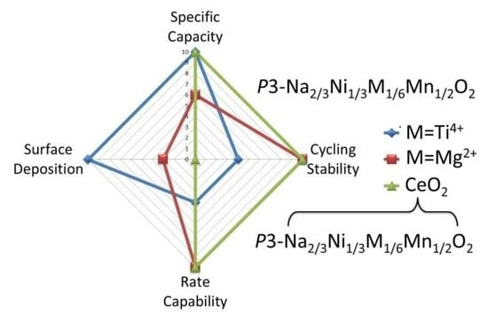
by
Mariya Kalapsazova
,
Rositsa Kukeva
,
Ekaterina Zhecheva
and
Radostina Stoyanova
*
Institute of General and Inorganic Chemistry, Bulgarian Academy of Sciences, 1113 Sofia, Bulgaria
*
Author to whom correspondence should be addressed.
Batteries 2022, 8(6), 56; https://doi.org/10.3390/batteries8060056
Submission received: 7 May 2022 / Revised: 3 June 2022 / Accepted: 8 June 2022 / Published: 15 June 2022
(This article belongs to the Special Issue Sodium-Ion Battery: Latest Advances and Prospects)

Abstract

:
Sodium-deficient nickel-manganese oxides with three-layered stacking exhibit the unique property of dual nickel-oxygen redox activity, which allows them to achieve enormous specific capacity. The challenge is how to stabilize the oxygen redox activity during cycling. This study demonstrates that oxygen redox activity of P3-Na2/3Ni1/2Mn1/2O2 during both Na+ and Li+ intercalation can be regulated by the design of oxide architecture that includes target metal substituents (such as Mg2+ and Ti4+) and oxygen storage modifiers (such as CeO2). Although the substitution for nickel with Ti4+ amplifies the oxygen redox activity and intensifies the interaction of oxides with NaPF6- and LiPF6-based electrolytes, the Mg2+ substituents influence mainly the nickel redox activity and suppress the deposition of electrolyte decomposed products (such as MnF2). The CeO2-modifier has a much stronger effect on the oxygen redox activity than that of metal substituents; thus, the highest specific capacity is attained. In addition, the CeO2-modifier tunes the electrode–electrode interaction by eliminating the deposition of MnF2. As a result, the Mg-substituted oxide modified with CeO2 displays high capacity, excellent cycling stability and exceptional rate capability when used as cathode in Na-ion cell, while in Li-ion cell, the best performance is achieved for Ti-substituted oxide modified by CeO2.

Graphical Abstract

1. Introduction

The transition to large-scale energy storage is dictated by the invention of more powerful, safer and cheaper batteries dictates [1]. These batteries are designed to replace the widely-used today lithium-ion batteries (LiIBs) without changing the mechanism of battery operation [2]. Nowadays, the most competitive alternatives of LiIBs are sodium-ion batteries (NaIBs) [3]. Both Li- and Na-batteries store energy by intercalation reactions occurring in the bulk of electrodes [2,3]. The intercalation reactions ensure excellent reversibility, but the specific capacity is limited by the redox properties of cationic constituents (such as transition metal ions Ni, Co, etc.) in the crystal structure of electrode materials [2]. This limitation can effectively be overcome if the redox activities of cationic and anionic constituents are unlocked simultaneously [4].
The unique property of dual redox activity of transition metal ions and lattice oxygen has been established for both the lithium and sodium transition metal oxides (i.e., LiTMOs and NaTMOs) [4,5]. Furthermore, this property is insensitive to the manner of layer stacking: for LiTMOs, the three-layer stacking is the stable structural configuration (i.e., O3-type), while for NaTMOs, both two- and three-layer stacking are observed (i.e., P2 and P3-types) [6]. Notwithstanding the common features of both oxides, the driving force for the activation of oxygen redox activity is different: for LiTMOs, the availability of even small amounts of Li ions in transition metal layers serves as a key trigger in the activation of oxygen redox reaction [7,8], while, for NaTMOs, the metal substitution at Mn4+-sites with mono-, bi- and four-valent ions (such as Li+ [9], Ni2+ [10], Mg2+ [11], Zn2+ [12], Cu2+ [13], Ti4+ [14], etc.), as well as the creation of vacancies in transition metal layers [15], is responsible for the oxygen redox activity. The common drawbacks for both LiTMOs and NaTMOs are the poor reversibility of the electrochemical reaction and the quick capacity fade during cycling [16]. The weak electrochemical features are a consequence of the electrochemically generated over-oxidized oxygen that leads to a destabilization of the layered structure and to an enhancement of the surface reactivity towards the acidic liquid electrolytes [15,17]. That is why the recent research efforts are mainly directed at the stabilization of lattice oxygen during the redox reaction.
There are several approaches for the stabilization of lattice oxygen that can be differentiated with respect to the manner of electrode modification. Concerning the oxide bulk, the reversible oxygen redox reactions in LiTMOs can be facilitated when the lattice oxygen is selectively replaced by fluorine or when the cations are disordered across transition metal and lithium layers [18,19]. The fluorination of LiTMOs affects not only the lattice oxygen but also evokes suppression in the irreversible gas release and surface reactions [18]. The co-doping of NaTMOs with lithium and titanium gives rise to the stabilization of lattice oxygen and to an enhancement of reversibility at oxygen redox reactions [20]. The surface coating of LiTMOs and NaTMOs is a common approach to inhibit, on one hand, the oxygen loss during the electrochemical reaction and, on the other, to suppress the side reactions between the electrode and the electrolyte [21,22,23]. The most used surface coatings are Al2O3, AlF3, AlPO4, MgO, TiO2 and Li2TiO3 [24,25,26]. Instead of metal oxides, surface decoration with an aim to stabilize underbonded oxidized O species in near-surface regions of oxides completely depleted of alkali ions is also used [27]. Thus, the sulfur deposition on Li-rich layered oxides is another approach that permits turning the under-coordinated surface oxygen into sulfate groups SO42−, thus depressing gas release and side reactions with the electrolyte [28]. To intensify the effect on the oxygen redox activity, a strategy including simultaneous doping and coating is also applied for both LiTMOs and NaTMOs [21,29]. The next strategy for depressing the oxygen evolution from LiTMOs is through surface doping with highly oxidized ions, such as Os, Sb, Ru, Ir, or Ta, which are prone to segregate on the oxide surface [30]. Recently, we have proposed a new concept for the stabilization of lattice oxygen in NaTMOs [31]. This concept comprises using oxygen-storage materials that serve as a buffer that accumulates the evolved oxygen during the complete alkali ion extraction from the layered oxide, and, during the reverse reaction, the accumulated oxygen will be returned to the layered oxide [30]. The concept is demonstrated in the case of three-layered sodium nickel manganese oxide P3-Na2/3Ni1/2Mn1/2O2. When the layered oxide is treated with an oxygen storage material, such as CeO2, there is a drastic increase in the reversible capacity during both the single intercalation of Na+ or Li+ and co-intercalation of Li+ and Na+ [30]. Based on the above findings, one can conclude that there is no unified concept of how to stabilize the lattice oxygen during the electrochemical reaction. That is why the rational manipulating of different factors that stabilize or destabilize the lattice oxygen will help to reveal the full potential of high-capacity oxide electrodes.
Herein, we unveil the interplay between metal substitution, treatment with oxygen storage materials and anionic redox activity in sodium nickel manganese oxides with three-layer stacking (P3-Na2/3Ni1/2Mn1/2O2) during single Na+ and Li+ intercalation. As metal substituents, Mg2+ and Ti4+ ions were used. The Mg2+ ions are selected since they induce reversible oxygen redox activity irrespective of the layered stacking (P2 and P3-modifications) [27,32,33], and they also allow avoiding the oxygen loss during the charging of the P2 phase at high potentials [27]. In comparison with Mg2+, the effect of Ti4+ ions on the oxygen redox activity is not so clear, but it is accepted that Ti4+ stabilizes the oxygen environment by strengthening the bonding between metal and oxygen and by decreasing the local ordering of transition metal ions [14,34]. In this study, the nominal composition of metal-substituted oxides is P3-Na2/3Ni1/3Mg1/6Mn1/2O2 and P3-Na2/3Ni1/3Ti1/6Mn1/2O2. Furthermore, the metal-substituted oxides are treated with an oxygen storage material, such as CeO2, which has been shown to have a dramatic effect on the performance of unsubstituted P3-Na2/3Ni1/2Mn1/2O2 [31]. The oxide architecture including metal substitution and oxygen-storage treatment allows achieving high capacity and improved cycling stability when electrode materials operate in Li- and Na-ion batteries.

2. Results and Discussions

2.1. Structure of Metal-Substituted and CeO2-Treated Oxides

The addition of Mg and Ti to P3-Na2/3Ni1/2Mn1/2O2 proceeds in the framework of the layered structure, where the manner of layer stacking and Na coordination are preserved (Figure S1). The lattice parameters are listed in Table 1. Although the Mg-substituted oxide exhibits unchanged lattice parameters, the incorporation of titanium into the layered oxide provokes a slight lattice expansion. The observed lattice dependences are related to the selective replacement of Ni2+ or Ni3+ ions in P3-Na2/3Ni1/2Mn1/2O2 by two-valent Mg2+ and four-valent Ti4+ ions. For the unsubstituted oxide P3-Na2/3Ni1/2Mn1/2O2, the charges of Na+ are compensated at the expense of the Ni ions (i.e., they adopt simultaneously the oxidation states of +2 and +3), while manganese ions are stabilized in an oxidation state of +4. [31,35]. The insertion of Mg2+ into P3-Na2/3Ni1/2Mn1/2O2 is accomplished through the replacement of Ni2+, which has an ionic radius close to that of Mg2+ (0.70 versus 0.72 Å). Contrary to Mg2+, the incorporation of Ti4+ ions takes place by replacing smaller, highly oxidized Ni ions (0.57 Å for Ni3+ versus 0.605 Å for Ti4+), thus leading to lattice expansion. However, the partial replacement of Mn4+ by Ti4+ cannot be rejected. Thus, the most possible structural formulas for Mg- and Ti-substituted oxides are Na2/3[Ni3+1/3Mg2+1/6Mn4+1/2]O2 and Na2/3[Ni2+1/3Ti4+1/6Mn4+1/2]O2.
The impregnation of metal-substituted oxides with cerium acetate, followed by thermal treatment at 700 °C, yields two-phase composites between layered oxides and CeO2 (Figure S1). The lattice parameters of the metal-substituted oxides in the composites remain intact, which indicates that the oxide bulk is free of any cerium ions (Table 1). This is valid for all samples, irrespective of the metal substituents.
To go inside the structure of metal-substituted and CeO2-treated oxides, an EPR spectroscopy is undertaken. Irrespective of the modification way, all oxides display a single line with a Lorentzian shape and a g-factor of 2.0. The main feature of the EPR signal is its strong temperature dependence: going from 300 to 100 K, the g-factor decreases together with line narrowing (Figure 1). This signal behavior reflects the exchange interactions between nickel and manganese ions inside the transition metal layers, as was previously established for the untreated P3-Na2/3Ni1/2Mn1/2O2 [33,36]. Given that Mg2+ and Ti4+ ions are diamagnetic and they substitute for paramagnetic nickel ions, one could expect different temperature dependencies of the g-factor and EPR line width for metal-substituted oxides. As can be expected, the Mg2+-substituted oxide possesses a g-factor that decreases more slowly on cooling in comparison with that of the unsubstituted oxide. In synchrony with the g-factor, the EPR line width is narrower in the whole temperature range between 300 and 100 K. This EPR signal behavior is consistent with the selective replacement of paramagnetic Ni2+ with diamagnetic Mg2+ ions, increasing the relative part of the Mn4+ ions. Contrary to the interactions between nickel and manganese ions, the exchange interactions between identical Mn4+ ions produce a narrower EPR signal with a g-factor independent of the registration temperature. For the sake of comparison, the EPR parameters of exchanged coupled Mn4+ ions in two-layer sodium manganese oxide (i.e., Р2-Na2/3MnO2) are g = 1.99 and a line width of around 90 mT [31,37].
Irrespective of the diamagnetic character, Ti4+ ions have a slight impact on the temperature dependence of both the g-factor and the EPR line width. The lack of significant dependence implies that Ti4+ ions provoke only slight changes in the ratio between paramagnetic nickel and manganese ions. This can be interpreted that Ti4+ ions substitute not only for nickel ions but also for manganese ions. However, these data do not allow quantifying the exact part of Ti that substitutes for Ni or Mn. Based on XRD and EPR data, one can conclude that highly oxidized Ni ions are dominant in Mg-substituted oxide, while in Ti-substituted oxide, low-oxidized Ni ions prevail.
The treatment of metal-substituted oxides with CeO2 does not induce any changes in the EPR parameters of the unmodified oxides (Figure 1). This evidences that the layered structure of metal-substituted oxides is free from cerium ions. On the other hand, the EPR data support once again that heating the impregnated oxide with cerium acetate enables obtaining two-phase composites between layered oxide and CeO2.
The next important characteristic of substituted and treated oxides is their morphology (Figure 2). All oxides display a morphology consisting of micro-metric aggregates, which are composed of nano-sized primary particles. The primary particles vary in size between 10 and 200 nm, and the most inhomogeneous particle distribution is observed for NNM. After treatment of NNM with CeO2, there is strong shrinkage in the particle sizes’ distribution with a center of gravity of around 10–40 nm. This trend is obeyed for CNM16, while for CNT16, it is not well pronounced. The common morphological features demonstrate that CeO2 modifies layered oxides in the same manner—CeO2 seems to suppress the particle aggregation.
Irrespective of the treatment type, the HR-TEM images display that, for all the samples, primary nanoparticles retain their good crystallinity (Figure 3). When layered oxides are modified with CeO2, lattice fringes are observed due to two phases. This means that, in modified oxides, there is intimate contact between particles of the two phases, which is developed at a nano-scale range (Figure 3).

2.2. Electrochemical Behavior of Metal-Substituted and CeO2-Treated Oxides

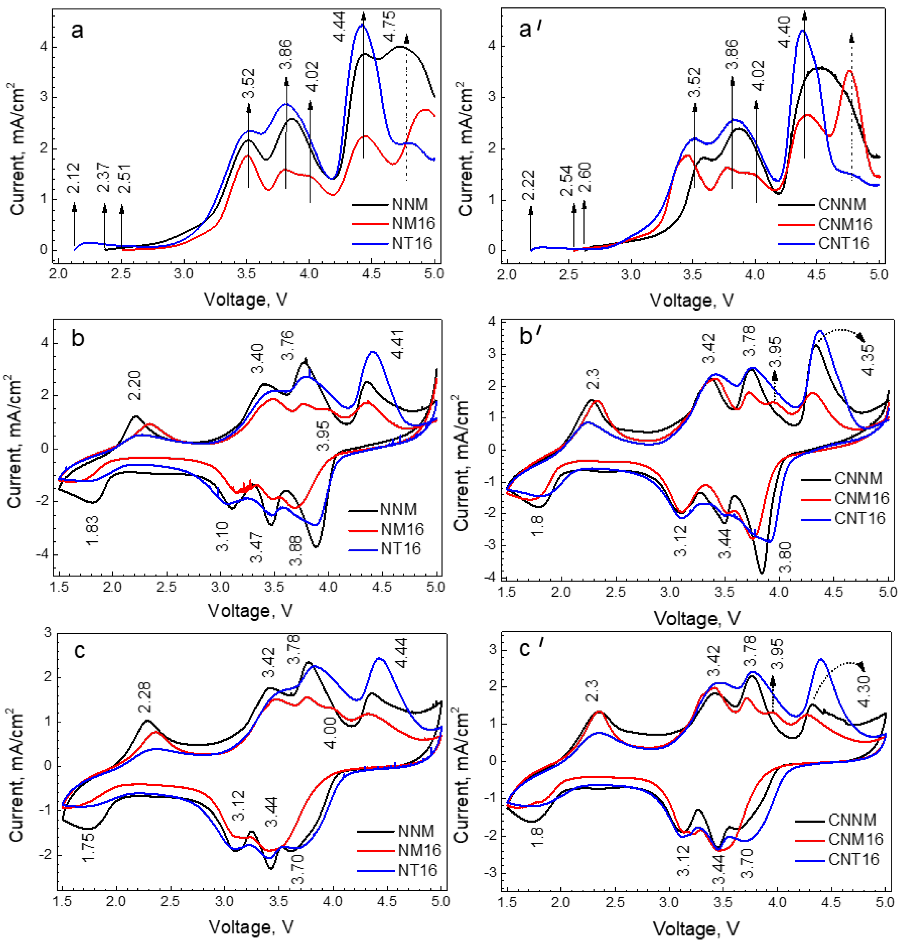
2.2.1. Sodium-Ion Cells

Metal-substituted oxides. The contribution of Mg2+ and Ti4+ to the electrochemical properties of NNM is monitored by CV (Figure 4). At first glance, the CV curves display similar profiles for all the samples. A close inspection, however, enables distinguishing some peculiarities.
The open circuit voltage (OCV) of cells increases from Ti- to Mg-substituted electrodes via unsubstituted NNM (Figure 3). Given that Mg2+ and Ti4+ ions are electrochemically inactive, this order reflects the oxidation state of nickel ions: the higher the Ni oxidation state, the higher OCV is. Thus, the observed increase in the OCV coincides with the structural data, according to which low-oxidized Ni ions are stabilized after Ti4+ substitution, while highly oxidized Ni ions appear after Mg2+-substitution, respectively.
After the first anodic scan, there are two intensive peaks in the 3V-range, whose positions are insensitive to the kind of metal substituents (i.e., peaks at 3.5 and 3.8 V, respectively). For the Mg-substituted oxide, an additional peak at 4.0 V superimposed on the main peak at 3.8 V appears. In the 4.0 V range, there are also two peaks: one at 4.4 V and the other above 4.7 V. The peak at 4.4 V is visible for all the samples, and it is most clearly pronounced for NT-16, while the peak above 4.7 V depends on the kind of metal substituents. The Mg2+ substituents shift the peak from 4.7 to 4.9 V, while the Ti4+ substituents significantly suppress this peak.
After the reverse cathodic scan process, four peaks grow in intensity, three of them being insensitive to the metal substituents at 3.4 V, 3.1 V and 3.4 V. The last peak at 3.9 V seems similar for NNM and NT-16, while for NM-16, this peak appears at a lower potential of 3.6 V.
The cycling entails a significant change in high-voltage peaks. The anodic peak at potentials above 4.7 V disappears after the first scan. The anodic and cathodic peaks at 4.4 V and 3.9 V are broadening and are shifting to lower potentials upon cycling—this being more significant for the Mg-substituted oxide. The redox peaks at the potentials of (3.5 V–3.8 V)/(3.2 V–3.5 V), as well as the low-voltage peak at 2.2/1.8 V, remain intact upon cycling. The stable curve profile is achieved after five cycles.
Based on our previous study on P3-Na2/3Ni1/2Mn1/2O2, the redox peaks in the range of 3.2–3.8 V are due to the partial sodium extraction/insertion inducing a reversible monoclinic distortion of the layered structure [35,38]. The sodium charges are compensated through the redox activity of nickel ions (i.e., Ni2+/Ni3+/Ni4+). The comparison of the CV curve profiles discloses that Ti4+ substituents do not influence the reaction of partial Na-extraction/insertion from/into the layered structure, while Mg2+ substituents have a slight impact manifesting as the appearance of an additional peak at 3.9 V. Between 4.2 and 4.5 V, the complete extraction of Na+ is achieved, which yields a restoration of the crystal structure [33,38]. In this voltage range, both nickel ions and lattice oxygen are involved in the electrochemical reaction. Among metal substituents, it appears that Ti4+ ions amplify the peak associated with nickel and oxygen redox activity. Because of the irreversibility of the anodic peak above 4.7 V, it can be attributed to a side reaction of electrolyte decomposition initiated by interaction with the oxide electrode. It is interesting that this process takes place easily at unsubstituted oxide. For Mg-substituted oxide, the electrolyte decomposition begins at higher potentials, while at the Ti-substituted oxide, this reaction is suppressed.
To outline the effect of metal substituents on the cationic and oxygen redox activity, Figure 5 compares the specific capacity delivered by NNM, NM-16 and NT-16 in two voltage ranges: in the limited voltage range of 2.0 V–4.2 V, where cations are only redox active, and in the extended voltage range of 2.0–4.3 V, where the oxygen redox activity is unlocked. The voltage ranges are selected in a way to avoid electrolyte decomposition. For the sake of convenience, the charge–discharge curves for metal-substituted oxides are given in Figure 5. Figure 4 shows the corresponding cycling stability and rate capability of oxides. In the limited voltage range, the specific capacity and cycling stability are comparable for all the samples. Even in this case, the Mg-substituted oxide displays a better rate capability in comparison with NNM and NT-16. This observation can be associated with a slight impact of the Mg2+ substituents on the reaction of partial Na-extraction/insertion (Figure 4).
In contrast, in the extended voltage range, the Ti-substituted oxide delivers the highest capacity (i.e., around 170 mAh/g) with moderate cycling stability (i.e., around 78% at C/10) and poorest rate capability (i.e., the capacity loss more than three times going from C/10 to 5C) (Figure 5). The Mg-substituted oxide is characterized by the lowest specific capacity (i.e., around 100 mAh/g), but it outperforms the other oxides in respect of the cycling stability (i.e., around 100%) and rate capability (i.e., the capacity loss less than two times going from C/10 to 5C). The unsubstituted oxide demonstrates the weakest performance in comparison with NM-16 and NT-16. The electrochemical results reveal that Ti4+ substituents amplify the oxygen redox activity of the layered oxide (Figure 4 and Figure 5), which could be correlated with the stabilization of low-oxidized nickel ions in Ti-containing oxides (Figure 2). In comparison with Ti4+, the Mg2+ substituents have an impact on the nickel redox activity before the activation of the oxygen redox reaction, thus contributing to the excellent cycling stability and rate capability of the layered oxides. The electrochemical impact of the Mg2+ substituents could be related to their aptitude to stabilize highly oxidized Ni ions in the layered oxide.
CeO2-treated oxides. After the oxide treatment with CeO2, the main features of the CV curves are preserved (Figure 4). The OCV increases from Ti- to Mg-substituted oxides. The redox peaks at (3.5 V–3.8 V)/(3.2 V–3.5 V) are similar for all the treated oxides. For CNM16, the low-intensive peak at 4.0 V is superimposed on the main anodic peak at 3.8 V, as in the case of the untreated oxides. The main difference between metal-substituted oxides and their CeO2-treated analogues is related to the peaks appearing in the 4.0 V region. The CeO2 additives amplify the redox peak at 4.4 V/3.9 V, and this peak is still visible after five cycles, especially for the Mg-substituted oxide. The irreversible anodic peak at 4.7 V seems to shift towards lower potentials for CNNM and CNM16 and remains hardly visible for CNT16, as was established for untreated NT16. This means that CeO2 has an impact on both the oxygen redox activity and the electrode–electrolyte interaction.
The charge–discharge curves support, once again, the effect of CeO2 on the electrochemical properties of layered oxides (Figure 6). To activate oxygen redox activity, the upper voltage limit is raised up to 4.5 V, just before the beginning of the electrode–electrolyte interaction. At a low charging rate (i.e., at C/20), the first specific capacity increases for all the oxides treated with CeO2: from 120, 100 and 170 mAh/g to 150, 205 and 210 mAh/g for CNNM, CNM16 and CNT16. This increase is spectacular for the Mg-substituted oxide (i.e., about two times). It is worth mentioning that CeO2 is not electrochemically active in this voltage window: between 1.5 and 4.5 V, CeO2 delivers a capacity of less than 1 mAh/g (Figure S2). The cycling stability is also impressive for this oxide: after 20 cycles at a rate of C/20, the cycling stability is 90% for CNM16 versus 68 % and 56 % for CNNM and CNT16. Among all oxides, the worst cycling stability is displayed by CNT16. It is interesting that the cycling stability resembles that of the metal-substituted oxides. Furthermore, the rate capability of CNM16 outperforms those of CNNM and CNT16. These data imply that CeO2 provokes an increase in the specific capacity of layered oxides, while metal substituents control their cycling stability and rate capability.

2.2.2. Lithium-Ion Cells

In addition to Na+, three-layered oxides are able to intercalate Li+ too (Figure 7). In Li-ion cells, the OCV increases from Ti- to Mg-substituted oxides irrespective of the CeO2-treatment, which is another experimental sign of the alteration in the Ni oxidation state after metal substitution. It is worth mentioning that the OCV values of oxides in Li-ion cells are much more than that in Na-ion cells (i.e., exceed significantly 0.3 V corresponding to the difference in the standard potential of Li/Li+ and Na/Na+, Figure 4 and Figure 7). This is a consequence of the partial extraction of Na+ and/or Li+/Na+ exchange induced by lithium electrolyte before the electrochemical reaction [31]. Thus, the first anodic scan in Li-ion cells embodies the extraction of the last Na+ ions from the layered oxide (i.e., less resolved peaks between 3.0 and 4.0 V). Above 4.0 V, the CV curve of NNM is dominated by two intensive peaks at 4.17 and 4.65 V. The metal substitution leads to a smooth shift in the peak from 4.17 to 4.33 V following the order NNM < NM16 < NT16. After the oxide treatment with CeO2, there is a slight lowering in the peak position, but the observed order remains unchanged: CNM < CNM16 < CNT16. For all the oxides, this peak becomes more intensive after the Ti substitution and CeO2 treatment. The next anodic peak at 4.65 V is suppressed for the metal-substituted oxide and their CeO2-treated analogues. After 4.8 V, the strong increase in the anodic current implies electrolyte decomposition, which is most pronounced for the Mg-substituted oxide.
The reverse cathodic scan produces the appearance of several peaks between 4.1 and 2.0 V, some of them not being recovered during cell cycling. The stable CV curves are observed after five cycles. This behavior is valid for all the substituted and treated oxides. The CV curves consist of two redox peaks at 4.2 V/3.6 V and 3.4 V/2.7 V. The metal substituents and CeO2 modifiers have an impact on the positions of these peaks, which is more pronounced for the high-voltage peak. The Ti4+ substituent leads to the strongest shift in the high-voltage peak, while for the Mg2+ substituent, the peak position is intermediate between those of NNM and NT16. The same picture is visible for the CeO2-treated oxides.
The Mg2+/Ti4+ substituents and CeO2 modifiers also affect the specific capacity, cycling stability and rate capability of layered oxides (Figure 8). The specific capacity of the substituted oxides increases following the order Mg2+ < Ti4+ (Figure 8). This order becomes inverted concerning the cycling stability: 72% for NNM, 81% for NM16 and 69% for NT16 at a rate of C/20. In accordance with the cycling stability, the rate capability is also better for the Mg2+-substituted oxides (Figure 8). The treatment of layered oxides with CeO2 leads to a strong increase in the specific capacity, as a result of which all the modified oxides deliver the close discharge capacities (i.e., about 170–190 mAh/g). It is important that the cycling stability and rate capability are also comparable for all the treated oxides and that they outperform those of the untreated oxides: the cycling stability is 77% for CNNM, 86% for CNM16 and 82% for CNT16 at a rate of C/20. At a rate of C/2 and a broad voltage window (i.e., between 1.5 and 4.8 V), the high capacity is delivered by CNT16 (i.e., around 150 mAh/h), while the cycling stability remains comparable for all the treated oxides (Figure 8). This confirms the good cycling stability of the treated oxides even in the extended voltage range, where the well-known Li-rich layered oxides failed [8].
The electrochemical results reveal that, during Li+ intercalation into layered oxides, the Ti4+ and Mg2+ substituents amplify the oxygen redox activity to a lesser extent than the CeO2 modifier does. In addition, the CeO2-treated oxides demonstrate better cycling and rate capability.

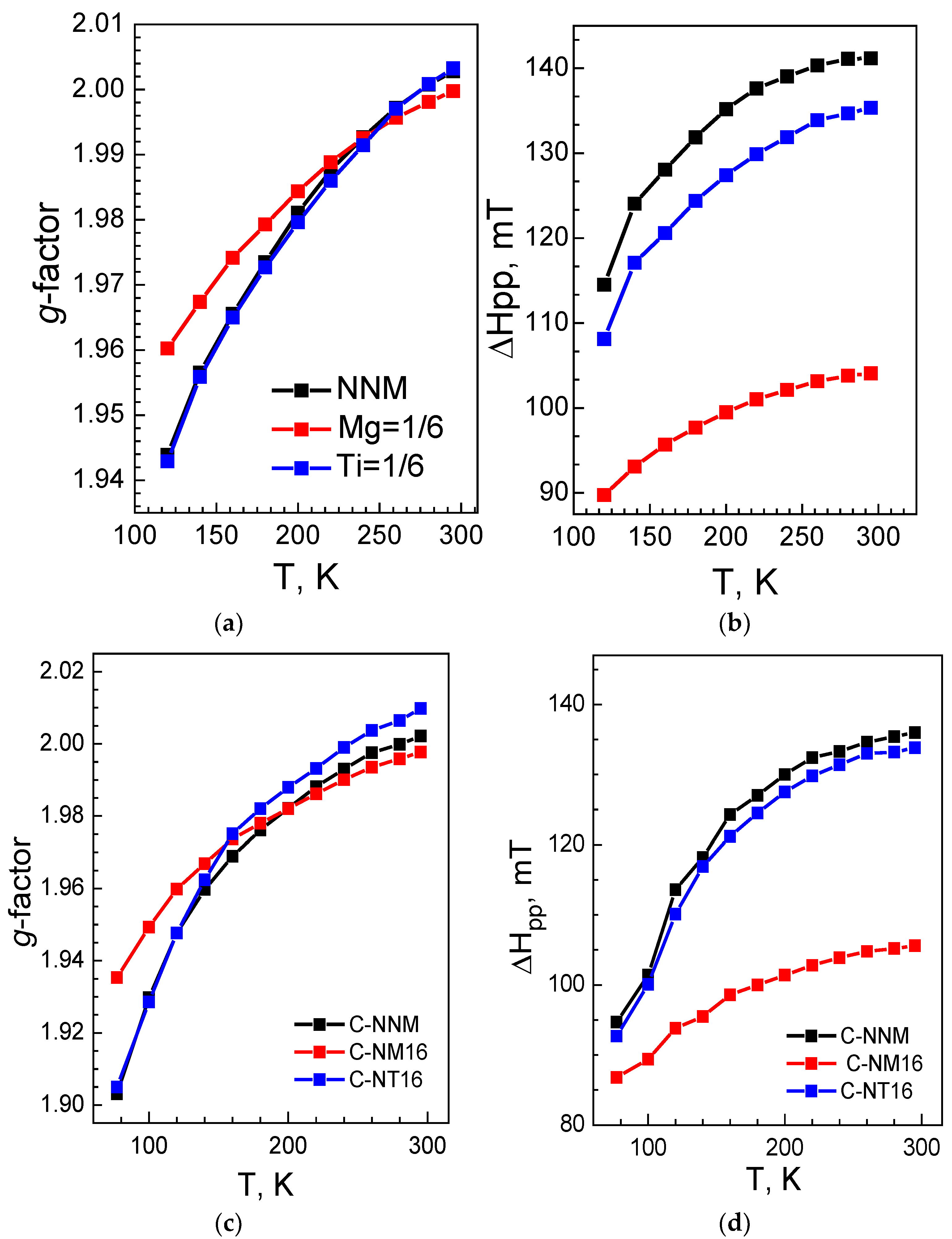
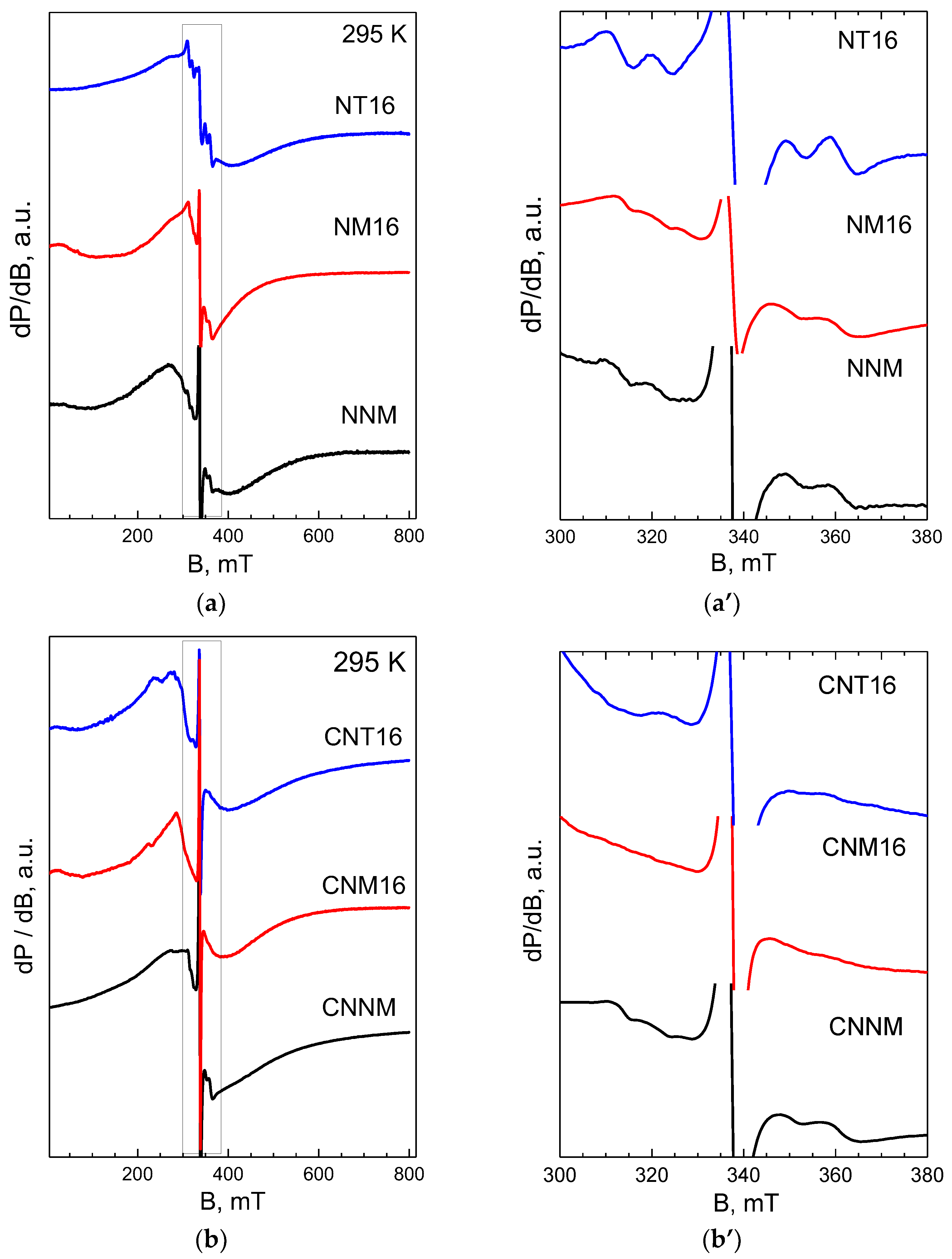
2.3. Surface Deposition after Na+ and Li+ Intercalation

2.3.1. Sodium Electrolyte

The CV curves indicate that metal substituents and the CeO2 modifier also influence the electrode–electrolyte interaction. The possible interaction is monitored by EPR spectroscopy, which allows simultaneously assessing the bulk and surface of electrodes (Figure 9). This is the main advantage of EPR spectroscopy over the surface XPS technique [31]. The EPR spectra of electrodes are dominated by the broad Lorentzian line due to the exchange of coupled nickel and manganese ions (Figure 9). Both the g-factor and EPR line width seem comparable with those for the pristine electrodes irrespective of the metal substituents or CeO2 modifier: at 295 K, the g-factor is close to 2.0, and the EPR line width reaches the following values: 140 mT for pristine NNM versus 125 mT and 130 mT for NNM and CNNM electrodes; 105 mT for pristine NM16 versus 105 mT and 115 mT for NM16 and CNM16 electrodes; 130 mT for pristine NT16 versus 125 mT and 140 mT for NT16 and CNT16 electrodes. This is a clear indication that Ni-Mn spin systems in the bulk of the metal-substituted and CeO2-treated oxides are preserved after electrode cycling.
The most important difference between pristine and cycled electrodes is the appearance of a hyperfine sextet signal with a g-factor of 2.0 and a hyperfine structure of 9.4 mT (Figure 9). The EPR parameters match those previously established for Mn2+ in MnF2 (an average g-factor of 2.0017 and an average hyperfine structure of 9.17 mT) [39]. Based on this comparison, the sextet signal detected at oxide electrodes can be attributed to Mn2+ ions surrounded by F ions. The simultaneous appearance of the sextet and the main signal implies that the Mn2+-F complexes are magnetically isolated from the main Ni-Mn spin system, thus allowing locating them on the oxide surface. Mn2+-F complexes originate from the electrode–electrolyte interaction. It is well recognized that fluorine-based electrolytes attack the oxide electrode (especially at voltages higher than 4.2 V), leading to a series of reactions, including transition metal dissolution, surface reconstruction, surface deposition of decomposed products (such as fluorides, carboxylates, carbonates, hydroxides, etc.), which, in turn, are responsible for capacity fading at layered oxides [40].
Because of the hyperfine structure and high sensitivity towards Mn2+ ions, EPR spectroscopy enables detecting some of the surface manganese products, such as manganese fluorides, on the layered oxides. To quantify them, we used the relative intensity of the sextet signal. The relative intensity is highest for the Ti-substituted oxide and lowest for the Mg-substituted oxide (i.e., 0.7, 0.5 and 1.0 for NNM, NM16 and NT16). After treating oxides with CeO2, the sextet signal drastically decreases, and it becomes hardly visible: for CNNM, it is less than 0.2, while for CNM16 and CNT16, it is practically not detectable. This proves that the Ti4+ substituents favor the surface interaction of layered oxides with NaPF6-based electrolytes, leading to the deposition of MnF2, while Mg2+ substituents and CeO2 modifiers inhibit the surface deposition of MnF2. It is interesting that the EPR data on electrode–electrolyte interactions correlate well with the electrochemical properties of oxides. The deposed MnF2 seems to play a two-fold role: on the one hand, it passivates the electrode surface, thus preventing further interaction with electrolytes and their decomposition (illustrated by the dependence of the oxidation peak above 4.5 V on Mg2+, Ti4+ and CeO2, Figure 3 and Figure 6); on the other hand, it impedes the alkali ion transfer from the oxide surface into the bulk (illustrated by cycling stability and rate capability of Ti-substituted oxides, Figure 6 and Figure 8).
Based on electrochemical and ex situ EPR experiments, it appears that CeO2 has several impacts. First, CeO2 amplifies the peak due to oxygen redox activity; second, CeO2 shifts the high-voltage peak down due to the electrode–electrolyte interaction; third, CeO2 suppresses the deposition of MnF2 on the electrode surface. It is worth mentioning that, in fuel cells with polymer electrolyte membranes, non-stoichiometric CeO2−δ significantly improves the chemical stability of the membrane due to its ability to scavenge the in situ generated oxygen radicals [41]. At this level of study, there are no observations of CeO2’s possible impact on the decomposition of sodium electrolytes comprising 1 M NaPF6 solution in propylene carbonate. However, through the DFT study, it has been demonstrated that propylene carbonate undergoes oxidative decomposition with a formation of acetone radical and CO2 as the primary product [42]. That is why it is not possible to reject CeO2 modifiers operating as free-radical scavengers in sodium electrolytes.

2.3.2. Lithium Electrolyte

The EPR signals due to the oxide bulk and surface are also observed after the cycling of electrodes in lithium-ion cells instead of sodium ones (Figure 10). The bulk EPR signal undergoes more significant broadening during the lithium intercalation than that of sodium (Figure 9) [35,43]. The line broadening reflects the transformation from the P3 structure into the O3 structure, where a partial exchange between Li+ from lithium layers with Ni2+ ions of transition metal layers takes place. The comparison of the EPR spectra shows that Ti4+ ions and CeO2 modifier cause stronger line broadening than that of Mg2+. This can be related to higher capacities delivered by Ti-substituted and CeO2-modified oxides.
The surface sextet signal due to deposed MnF2 is also visible for oxide electrodes cycled in lithium-ion cells. The relative intensity of this signal is highest for the Ti-substituted oxide and lowest for the Mg-substituted oxide: 0.8, 0.5 and 1.0 for NNM, NM16 and NT16. After the oxide modification with CeO2, the sextet signal almost vanished (Figure 10). It is noticeable that the same order in the intensity variation is established for oxides cycled in sodium-ion cells. On the one hand, this reveals that LiPF6- and NaPF6-based electrolytes interact in the same way with oxide electrodes, resulting in MnF2 deposition. On the other hand, the interaction is modulated by metal substituents and CeO2; it is intensified by the Ti4+ ions and hindered by the Mg2+ ions and CeO2 modifier. The hindrance at MnF2 deposition facilitates, on one hand, the interaction between the oxide electrolyte and the electrolyte but, on the other hand, mitigates the alkali ions transfer from the oxide surface into the bulk. As a result, the CeO2-modified oxides display a better electrochemical performance both in sodium and lithium-ion cells.

3. Materials and Methods

3.1. Materials

Depending on the kind of metal substituents, two synthetic procedures were carried out. The Mg-substituted oxide, Na2/3Ni1/3Mg1/6Mn1/2O2, is obtained by freeze-drying aqueous solutions containing acetate salts of Na+, Ni2+, Mg2+ and Mn2+ ions, followed by thermal decomposition at 400 °C. The solid residues were ground, pelleted and annealed at 700 °C for 24 h. The details are given elsewhere [33].
The synthesis of Ti-substituted oxides is based on Pechini’s method. The initial reagents comprise nickel and manganese acetates, sodium nitrate, TiO2 (anatase type, ≥99%, Honeywell Fluka, Mecklenburg, NC, USA), citric acid and ethylene glycol. The synthetic method includes several steps. First, the acetate solution of nickel and manganese is prepared. Then, TiO2, citric acid and, finally, a nitrate solution of sodium are added sequentially to the acetate solution. The suspension is heated at 90 °C under vigorous stirring. The solution of ethylene glycol is slowly added to the suspension, and heating continued until a thick gel forms, followed by the decomposition of the gel at 400 °C in air. The decomposed products are treated in the same way as the magnesium-substituted oxides. For the sake of convenience, the unsubstituted and metal-substituted oxides will be denoted as NNM, NM16 and NT16, respectively.
The treatment of layered oxides with CeO2 is accomplished by impregnating NNM, NM16 and NT16 with an aqueous solution of cerium acetate (Cerium(III) acetate hydrate, 99.9% trace metals basis, Sigma Aldrich, St. Louis, MO, USA). The amount of cerium acetate is calculated to obtain 5 wt.% CeO2 in the target compound. The impregnated oxides are annealed at 700 °C for 2 h in an oxygen atmosphere. The treated oxides will be denoted as CNNM, CNM16 and CNT16, respectively.

3.2. Methods

The structure of oxides was determined by powder X-ray diffraction using the Bruker Advance D8 powder diffractometer with CuKα radiation (Germany). The TEM analysis was carried out on a JEOL 2100 microscope. The specimens were prepared in acetone by ultrasonic treatment. The suspensions were then dripped on standard holey carbon/Cu grids. The HR-TEM images were quantified by Digital Micrograph software. The EPR spectra were collected on a Bruker EMXplus spectrometer (Germany) within the temperature range of 100–400 K. The specific surface area of oxides varies between 1 and 3 m2/g without any clear dependence on the number of metal substituents and CeO2 modifiers.
The electrodes were fabricated by mixing the active material with carbon black (Super C65) and polyvinylidene fluoride (PVDF) in N-methyl-2-pyrrolidone at a dry weight ratio of 80:10:10. The slurry was cast on aluminum foil, followed by drying at 80 °C overnight. The disk electrodes with a diameter of 9 mm were cut, pressed and dried at 120 °C under vacuum. The mass loading of active material was 3.50 ± 0.5 mg.cm−2. The Swagelok-type cells were mounted in a glovebox (MBraun, MB-Unilab Pro SP (1500/780), H2O, and O2 content <0.1 ppm). The counter electrode consisted of clean lithium or sodium metal. As electrolytes, we applied 1 M LiPF6 in EC/DMC and 1M NaPF6 in PC. The separator comprises a Whatman GF/D glass microfiber layer. The cell testing was carried out using an Arbin battery cycler (Series LBT20084) in galvanostatic mode. The CV experiments were performed on Autolab PGStat 204 potentiostat. Each electrochemical experiment was repeated at least twice, showing a rather high reproducibility.
The ex situ EPR experiments were performed on the electrodes recovered from cells cycled 40 times between 1.5 and 4.5 V and switched off at 1.5 V. The electrochemical cells were disassembled inside the glovebox, and the recovered electrodes were subjected to a washing step with dimethyl carbonate (DMC) to eliminate electrolyte residues. The EPR quartz tube was filled with recovered electrodes inside the glovebox.

4. Conclusions

The morphology and electrochemical properties of P3-Na2/3Ni1/2Mn1/2O2 were effectively modified by Mg2+ and Ti4+ substitution complemented with CeO2 treatment. The incorporation of Mg2+ and Ti4+ ions into the layered structure of Na2/3Ni1/2Mn1/2O2 is accomplished through a selective replacement of low- and high-oxidized nickel ions, respectively. The impregnation of metal-substituted oxides with a small amount of cerium acetate leads to the formation of two-phase composites between layered oxide and CeO2, in which the layered structure remains intact, and the particle distribution becomes more homogeneous.
The Ti4+ substituents amplify the oxygen redox activity during Na+ and Li+ intercalation, thus permitting reaching the highest specific capacity at potentials above 4.2 V. At the same time, the interaction of oxides with NaPF6- and LiPF6-based electrolytes is intensified, leading to a deposition of MnF2. As a result, Ti-substituted oxide displays moderate cycling stability and poor rate capability. Contrary to Ti4+, the Mg2+ substituents mainly influence the nickel redox activity and suppress the deposition of MnF2, all of them contributing to the exceptional cycling stability and rate capability. The CeO2 modifier has a much stronger effect on the oxygen redox activity than that of metal substituents; thus, the highest specific capacity is attained. In addition, the CeO2 modifier tunes the electrode–electrode interaction by eliminating the deposition of MnF2.
By combining the appropriate substituents with the CeO2 modifier, the best electrode material was selected. For Na-ion cells, this is the Mg-substituted oxide modified with CeO2, which displays high capacity, excellent cycling stability and exceptional rate capability. For Li-ion cells, the Ti-substituted oxide modified by CeO2 display the best performance.
This study demonstrates that the oxygen redox activity of three-layered oxides can be regulated by a rational combination of metal substituents and oxygen storage modifiers. Although the CeO2 modifier provokes an increase in the specific capacity of layered oxides, the metal substituents control their cycling stability and rate capability. We think that the proposed oxide architecture that includes target metal substituents and oxygen-storage modifiers may open up new directions for the elaboration of electrode materials with colossal intercalation capacity and designed for both Li- and Na-ion batteries.

Supplementary Materials

The following supporting information can be downloaded at: https://www.mdpi.com/article/10.3390/batteries8060056/s1, Figure S1: XRD patterns of NNM, NM-16, NT-16 and their CeO2-treated analogues. Figure S2: Charge–discharge curves of CeO2 in a sodium-ion cell.

Author Contributions

Conceptualization, R.S. and M.K.; methodology, E.Z. and R.S.; software, M.K. and R.K.; validation, M.K. and R.K.; investigation, M.K. and R.K.; resources, R.S.; data curation, M.K.; writing—original draft preparation, R.S. and M.K.; writing—review and editing, E.Z. and R.S.; visualization, M.K. and R.K.; project administration, R.S.; funding acquisition, R.S. All authors have read and agreed to the published version of the manuscript.

Funding

This research was funded by the Bulgarian National Science Fund, grant number contract CARiM (NSP Vihren, КП-06-ДВ-6).

Institutional Review Board Statement

Not applicable.

Informed Consent Statement

Not applicable.

Data Availability Statement

Not applicable.

Acknowledgments

The authors acknowledge the financial support of the Bulgarian National Science Fund, contract CARiM (NSP Vihren, КП-06-ДВ-6). The MBRAUN glovebox was used within the framework of the National Center of Mechatronics and Clean Technologies (BG05M2OP001-1.001-0008). The authors are grateful to Diana Nihtianova for the TEM analysis.

Conflicts of Interest

The authors declare no conflict of interest.

References

  1. Gür, T.M. Review of electrical energy storage technologies, materials and systems: Challenges and prospects for large-scale grid storage. Energy Environ. Sci. 2018, 11, 2696–2767. [Google Scholar] [CrossRef]
  2. Whittingham, M.S. Special editorial perspective: Beyond Li-ion battery chemistry. Chem. Rev. 2020, 120, 6328–6330. [Google Scholar] [CrossRef] [PubMed]
  3. Abraham, K.M. How comparable are sodium-ion batteries to lithium-ion counterparts? ACS Energy Lett. 2020, 5, 3544–3547. [Google Scholar] [CrossRef]
  4. Rahman, M.M.; Lin, F. Oxygen redox chemistry in rechargeable Li-ion and Na-ion batteries. Matter 2021, 4, 490–527. [Google Scholar] [CrossRef]
  5. Lee, G.; Lau, V.W.; Yang, W.; Kang, Y. Utilizing oxygen redox in layered cathode materials from multiscale perspective. Adv. Energy Mater. 2021, 11, 2003227. [Google Scholar] [CrossRef]
  6. Delmas, C. Sodium and sodium-ion batteries: 50 years of research. Adv. Energy Mater. 2018, 8, 1703137. [Google Scholar] [CrossRef]
  7. Koga, H.; Croguennec, L.; Ménétrier, M.; Mannessiez, P.; Weill, F.; Delmas, C. Different oxygen redox participation for bulk and surface: A possible global explanation for the cycling mechanism of Li1.20Mn0.54Co0.13Ni0.13O2. J. Power Sources 2013, 236, 250–258. [Google Scholar] [CrossRef]
  8. He, W.; Guo, W.; Wu, H.; Lin, L.; Liu, Q.; Han, X.; Xie, Q.; Liu, P.; Zheng, H.; Wang, L.; et al. Challenges and recent advances in high capacity Li-rich cathode materials for high energy density lithium-ion batteries. Adv. Mater. 2021, 33, 2005937. [Google Scholar] [CrossRef]
  9. De La Llave, E.; Talaie, E.; Levi, E.; Nayak, P.K.; Dixit, M.; Rao, P.T.; Hartmann, P.; Chesneau, F.; Major, D.T.; Greenstein, M.; et al. Improving Energy Density and Structural Stability of Manganese Oxide Cathodes for Na-Ion Batteries by Structural Lithium Substitution. Chem. Mater. 2016, 28, 9064–9076. [Google Scholar] [CrossRef]
  10. Ma, C.; Alvarado, J.; Xu, J.; Clément, R.J.; Kodur, M.; Tong, W.; Grey, C.P.; Meng, Y.S. Exploring oxygen activity in the high energy P2-type Na0.78Ni0.23Mn0.69O2 cathode material for Na-ion batteries. J. Am. Chem. Soc. 2017, 139, 4835–4845. [Google Scholar] [CrossRef] [Green Version]
  11. Maitra, U.; House, R.A.; Somerville, J.W.; Tapia-Ruiz, N.; Lozano, J.G.; Guerrini, N.; Hao, R.; Luo, K.; Jin, L.; Pérez-Osorio, M.A.; et al. Oxygen redox chemistry without excess alkali-metal ions in Na2/3[Mg0.28Mn0.72]O2. Nat. Chem. 2018, 10, 288–295. [Google Scholar] [CrossRef] [PubMed]
  12. Bai, X.; Sathiya, M.; Mendoza-Sánchez, B.; Iadecola, A.; Vergnet, J.; Dedryvère, R.; Saubanère, M.; Abakumov, A.M.; Rozier, P.; Tarascon, J.M. Anionic redox activity in a newly Zn-doped sodium layered oxide P2-Na2/3Mn1−y Zn y O2 (0 < y < 0.23). Adv. Energy Mater. 2018, 8, 1802379. [Google Scholar]
  13. Wang, Y.; Kim, S.; Lu, J.; Feng, G.; Li, X. A study of Cu doping effects in P2-Na0.75Mn0.6Fe0.2(CuxNi0.2-x)O2 layered cathodes for sodium-ion batteries. Batter. Supercaps 2020, 3, 376–387. [Google Scholar] [CrossRef]
  14. Zhao, C.; Yao, Z.; Wang, J.; Lu, Y.; Bai, X.; Aspuru-Guzik, A.; Chen, L.; Hu, Y.-S. Ti Substitution facilitating oxygen oxidation in Na2/3Mg1/3Ti1/6Mn1/2O2 cathode. Chem. 2019, 5, 2913–2925. [Google Scholar] [CrossRef]
  15. Mortemard de Boisse, B.; Nishimura, S.-I.; Watanabe, E.; Lander, L.; Tsuchimoto, A.; Kikkawa, J.; Kobayashi, E.; Asakura, D.; Okubo, M.; Yamada, A. Highly reversible oxygen-redox chemistry at 4.1 V in Na4/7–x[□1/7Mn6/7]O2 (□: Mn vacancy). Adv. Energy Mater. 2018, 8, 1800409. [Google Scholar] [CrossRef]
  16. Kubota, K.; Komaba, S. Review-practical issues and future perspective for Na-ion batteries. J. Electrochem. Soc. 2015, 162, A2538–A2550. [Google Scholar] [CrossRef]
  17. Xu, J.; Sun, M.; Qiao, R.; Renfrew, S.; Ma, L.; Wu, T.; Hwang, S.; Nordlund, D.; Su, D.; Amine, K.; et al. Elucidating anionic oxygen activity in lithium-rich layered oxides. Nat. Commun. 2018, 9, 947. [Google Scholar] [CrossRef]
  18. Lee, J.; Papp, J.K.; Clément, R.J.; Sallis, S.; Kwon, D.-H.; Shi, T.; Yang, W.; McCloskey, B.; Ceder, G. Mitigating oxygen loss to improve the cycling performance of high capacity cation-disordered cathode materials. Nat. Commun. 2017, 8, 981. [Google Scholar] [CrossRef]
  19. Zhou, K.; Zheng, S.; Ren, F.; Wu, J.; Liu, H.; Luo, M.; Liu, X.; Xiang, Y.; Zhang, C.; Yang, W.; et al. Fluorination effect for stabilizing cationic and anionic redox activities in cation-disordered cathode materials. Energy Storage Mater. 2020, 32, 234–243. [Google Scholar] [CrossRef]
  20. Li, Z.; Kong, W.; Yu, Y.; Zhang, J.; Wong, D.; Xu, Z.; Chen, Z.; Schulz, C.; Bartkowiak, M.; Liu, X. Tuning bulk O2 and nonbonding oxygen state for reversible anionic redox chemistry in P2-layered cathodes. Angew. Chem. Int. Ed. Engl. 2022, 134, e202115552. [Google Scholar]
  21. Kaur, G.; Gates, B.D. Review—Surface coatings for cathodes in lithium ion batteries: From crystal structures to electro-chemical performance. J. Electrochem. Soc. 2022, 169, 043504. [Google Scholar] [CrossRef]
  22. Nisar, U.; Muralidharan, N.; Essehli, R.; Amin, R.; Belharouak, I. Valuation of surface coatings in high-energy density lithium-ion battery cathode materials. Energy Storage Mater. 2021, 38, 309–328. [Google Scholar] [CrossRef]
  23. Shi, C.; Wang, L.; Chen, X.; Wang, S.; Wang, J.; Jin, H. Challenges of layer-structured cathodes for sodium-ion bat-teries. Nanoscale Horiz. 2022, 7, 338–351. [Google Scholar] [CrossRef] [PubMed]
  24. Hwang, J.-Y.; Myung, S.-T.; Choi, J.U.; Yoon, C.S.; Yashiro, H.; Sun, Y.-K. Resolving the degradation pathways of the O3-type layered oxide cathode surface through the nano-scale aluminum oxide coating for high-energy density sodium-ion batteries. J. Mater. Chem. A 2017, 5, 23671–23680. [Google Scholar] [CrossRef]
  25. Wang, Y.; Tang, K.; Li, X.; Yu, R.; Zhang, X.; Huang, Y.; Chen, G.; Jamil, S.; Cao, S.; Xie, X.; et al. Improved cycle and air stability of P3-Na0.65Mn0.75Ni0.25O2 electrode for sodium-ion batteries coated with metal phosphates. Chem. Eng. J. 2019, 372, 1066–1076. [Google Scholar] [CrossRef]
  26. Yu, Y.; Kong, W.; Li, Q.; Ning, D.; Schuck, G.; Schumacher, G.; Su, C.; Liu, X. Understanding the multiple effect of TiO2 coating on NaMn0.33Fe0.33Ni0.33O2 cathode material for Na-ion batteries. ACS Appl. Energy Mater. 2020, 3, 933–942. [Google Scholar] [CrossRef] [Green Version]
  27. House, R.A.; Maitra, U.; Jin, L.; Lozano, J.G.; Somerville, J.W.; Rees, N.H.; Naylor, A.J.; Duda, L.C.; Massel, F.; Chadwick, A.V.; et al. What triggers oxygen loss in oxygen redox cathode materials? Chem. Mater. 2019, 31, 3293–3300. [Google Scholar] [CrossRef] [Green Version]
  28. Chen, Q.; Pei, Y.; Chen, H.; Song, Y.; Zhen, L.; Xu, C.-Y.; Xiao, P.; Henkelman, G. Highly reversible oxygen redox in layered compounds enabled by surface polyanions. Nat. Commun. 2020, 11, 3411. [Google Scholar] [CrossRef]
  29. Hwang, J.-Y.; Yu, T.-Y.; Sun, Y.-K. Simultaneous MgO coating and Mg doping of NaNi0.5Mn0.5O2 cathode: Facile and customizable approach to high-voltage sodium-ion batteries. J. Mater. Chem. A 2018, 6, 16854–16862. [Google Scholar] [CrossRef]
  30. Shin, Y.; Kan, W.H.; Aykol, M.; Papp, J.K.; McCloskey, B.D.; Chen, G.; Persson, K.A. Alleviating oxygen evolution from Li-excess oxide materials through theory-guided surface protection. Nat. Commun. 2018, 9, 4597. [Google Scholar] [CrossRef] [Green Version]
  31. Kalapsazova, M.L.; Kostov, K.L.; Kukeva, R.R.; Zhecheva, E.N.; Stoyanova, R.K. Oxygen-storage materials to stabilize the oxygen redox activity of three-layered sodium transition metal oxides. J. Phys. Chem. Lett. 2021, 12, 7804–7811. [Google Scholar] [CrossRef] [PubMed]
  32. Song, B.; Hu, E.; Liu, J.; Zhang, Y.; Yang, X.-Q.; Nanda, J.; Huq, A.; Page, K. A novel P3-type Na2/3Mg1/3Mn2/3O2 as high capacity sodium-ion cathode using reversible oxygen redox. J. Mater. Chem. A 2019, 7, 1491–1498. [Google Scholar] [CrossRef]
  33. Kalapsazova, M.; Markov, P.; Kostov, K.; Zhecheva, E.; Nihtianova, D.; Stoyanova, R. Controlling at elevated temperature the sodium intercalation capacity and rate capability of P3-Na2/3Ni1/2Mn1/2O2 through the selective substitution of nickel with magnesium. Batter. Supercaps 2020, 3, 1329–1340. [Google Scholar] [CrossRef]
  34. Lee, J.; Koo, S.; Lee, J.; Kim, D. Rational design of Ti-based oxygen redox layered oxides for advanced sodium-ion batteries. J. Mater. Chem. A 2021, 9, 11762–11770. [Google Scholar] [CrossRef]
  35. Yang, J.; Maughan, A.E.; Teeter, G.; de Villers, B.J.T.; Bak, S.; Han, S. Structural stabilization of P2-type sodium iron manganese oxides by electrochemically inactive Mg substitution: Insights of redox behavior and voltage decay. ChemSusChem 2020, 13, 5972–5982. [Google Scholar] [CrossRef] [PubMed]
  36. Stansby, J.H.; Sharma, N.; Goonetilleke, D. Probing the charged state of layered positive electrodes in sodium-ion batteries: Reaction pathways, stability and opportunities. J. Mater. Chem. A 2020, 8, 24833–24867. [Google Scholar] [CrossRef]
  37. Zhu, Y.-F.; Xiao, Y.; Dou, S.-X.; Chou, S.-L. Dynamic structural evolution and controllable redox potential for abnormal high-voltage sodium layered oxide cathodes. Cell Rep. Phys. Sci. 2021, 2, 100631. [Google Scholar] [CrossRef]
  38. Zhang, J.; Wang, W.; Wang, W.; Wang, S.; Li, B. Comprehensive review of P2-type Na2/3Ni1/3Mn2/3O2, a potential cathode for practical application of Na-ion batteries. ACS Appl. Mater. Interfaces 2019, 11, 22051–22066. [Google Scholar] [CrossRef]
  39. Yosida, T.; Aoki, H.; Takeuchi, H.; Arakawa, M.; Horai, K. EPR, 19F-ENDOR and 55Mn-ENDOR of Mn2+ impurity center in MgF2 single crystal. J. Phys. Soc. Jpn. 1991, 60, 625–635. [Google Scholar] [CrossRef]
  40. Huang, Y.; Zhao, L.; Li, L.; Xie, M.; Wu, F.; Chen, R. Electrolytes and electrolyte/electrode interfaces in sodium-ion batteries: From scientific research to practical application. Adv. Mater. 2019, 31, e1808393. [Google Scholar] [CrossRef]
  41. Kumar, A.; Hong, J.; Yun, Y.; Bhardwaja, A.; Song, S.-J. The role of surface lattice defects of CeO2−δ nanoparticles as a scav-enging redox catalyst in polymer electrolyte membrane fuel cells. J. Mater. Chem. A 2020, 8, 26023–26034. [Google Scholar] [CrossRef]
  42. Leggesse, E.G.; Lin, R.T.; Teng, T.-F.; Chen, C.-L.; Jiang, J.-C. Oxidative decomposition of propylene carbonate in lithium ion batteries: A DFT study. J. Phys. Chem. A 2013, 117, 7959–7969. [Google Scholar] [CrossRef] [PubMed]
  43. Kalapsazova, M.; Kostov, K.; Zhecheva, E.; Stoyanova, R. Hybrid Li/Na ion batteries: Temperature-induced reactivity of three-layered oxide (P3-Na2/3Ni1/3Mg1/6Mn1/2O2) toward lithium ionic liquid electrolytes. Front. Chem. 2020, 8, 600140. [Google Scholar] [CrossRef] [PubMed]
Figure 1. Temperature dependence of the g-factor and EPR line width (ΔHpp) of NNM, NM16, NT16 (a,b) and their CeO2-treated analogues (c,d).
Batteries 08 00056 g001
Figure 2. Bright-field TEM images and corresponding particle size–distribution curves for NNM, NM16, NT16 (ac) and their CeO2-treated analogues (CNNM, CNM16 and CNT16) (df).
Batteries 08 00056 g002
Figure 3. HR-TEM images of CNM16 (a) and CNT16 (b). The lattice fringes from the layered oxide (LO) and CeO2-δ are indicated.
Batteries 08 00056 g003
Figure 4. CV curves of metal-substituted oxides (ac) and their CeO2-treated analogues (a’c’) in sodium-ion cells: (i) first anodic scan (a,a’); (ii) the corresponding cathodic scan and next anodic scan (b,b’); (iii) CV curves after five cycle (c,c’). The scan rate is 1 mV/s.
Batteries 08 00056 g004
Figure 5. Specific capacity, cycling stability and rate capability for NNM, NM16 and NT16 in sodium-ion cells cycled in two voltage windows: (a)—[4.2–2.1] V and (b)—[4.3–2.0] V. Charge–discharge curves after the 1st (c) and 20th (d) cycles for NNM, NM16 and NT16 in sodium-ion cells.
Batteries 08 00056 g005
Figure 6. Charge–discharge curves after the 2nd cycle for CNNM, CNM16 and CNT16 in sodium-ion cells (a). Specific capacity, cycling stability and rate capability for CNNM, CNM16 and CNT16 in sodium-ion cells (b).
Batteries 08 00056 g006
Figure 7. CV curves of metal-substituted oxides (ac) and their CeO2-treated analogues (a’c’) in lithium-ion cells: (i) first anodic scan (a,a’); (ii) the corresponding cathodic scan and next anodic scan (b,b’); (iii) CV curves after five cycle (c,c’). The scan rate is 1 mV/s.
Batteries 08 00056 g007
Figure 8. Specific capacity, cycling stability and rate capability for NNM, NM16 and NT16 (a) and their CeO2-treated analogues CNNM, CNM16 and CNT16 (b) in lithium-ion cells worked between 1.5 and 4.5 V. The cycling stability for CNNM, CNM16 and CNT16 at a rate of C/2 between 1.5 and 4.8 V (c).
Batteries 08 00056 g008
Figure 9. EPR spectra of metal-substituted oxides (a) and CeO2-treated analogues (b) after cycling in sodium-ion cells between 1.5 and 4.5 V for 40 times (the cell is switched off at 1.5 V). The parts of the spectra in the narrow range of the magnetic field (i.e., between 300 and 380 mT) are also shown (a’,b’).
Batteries 08 00056 g009
Figure 10. EPR spectra of metal-substituted oxides (a,a’) and CeO2-treated oxides (b,b’) after cycling in lithium-ion cells. The right figures present the EPR spectra in the narrow range of the magnetic field. The parts of the spectra in the narrow range of magnetic field (i.e., between 300 and 385 mT) are also shown (a’,b’).
Batteries 08 00056 g010
Table 1. Lattice parameters for Na2/3Ni1/2Mn1/2O2, Na2/3Ni1/3Mg1/6Mn1/2O2, Na2/3Ni1/3Ti1/6Mn1/2O2 and their CeO2-treated analogues.
Samplesa ± 0.0001, Åс ± 0.002, ÅV ± 0.02, Å3
NNM2.886716.7692121.01
NM162.888916.7789121.27
NT162.899216.8237122.46
CNNM2.887216.7724121.09
CNM162.886716.7732121.29
CNT162.888916.8236122.54
Publisher’s Note: MDPI stays neutral with regard to jurisdictional claims in published maps and institutional affiliations.

