Article

Experimental Analysis of the Effect of Limescale on the Wettability of Indirect Evaporative Cooling System Plates

1
Department of Energy, Politecnico di Milano, Via Lambruschini 4, 20156 Milano, Italy
2
Recuperator S.p.A., Via Valfurva 13, 20027 Rescaldina, Italy
*
Author to whom correspondence should be addressed.
Fluids 2024, 9(3), 76; https://doi.org/10.3390/fluids9030076
Submission received: 5 March 2024 / Revised: 14 March 2024 / Accepted: 15 March 2024 / Published: 17 March 2024
(This article belongs to the Special Issue Fluids and Surfaces, 2nd Edition)

Abstract

:
Indirect evaporative cooling systems have attracted much interest in recent years as they guarantee good cooling effectiveness, with lower energy demand with respect to traditional systems, thus helping to address the issue of climate change. Many studies have shown that an increase in the wettability of recuperator plates results in an improvement in the system performance. However, if the water injected into the system comes from the city water supply, it will contain calcium carbonate residuals, which will form limescale layers on the plates, thus possibly changing their wetting behavior. Therefore, the wettability of three surfaces (an aluminum uncoated surface, AL, a standard epoxy coating, STD, and a hydrophilic lacquer, HPHI) was analyzed in the presence of limescale formations, and compared with that obtained in a previous study for corresponding clean surfaces. The results showed that the HPHI contact angle was reduced in the presence of limescale (median: 50°), that for STD was slightly increased (median: 81°), and that for AL was again reduced (median: 75°). Consequently, HPHI was confirmed to be the most wettable surface in both clean and limescale conditions. Finally, an analysis was undertaken evaluating the spreading factor and the reversible work of adhesion, which were in good agreement with the qualitative visual observations of the plates covered with limescale.

1. Introduction

In recent years, indirect evaporative cooling (IEC) systems have attracted the interest of researchers and companies, as they can guarantee good cooling effectiveness with lower energy demand compared with traditional air conditioning solutions [1], thus potentially representing a promising technology to help address the problem of climate change. IEC systems reduce the product air temperature using the latent heat of vaporization of water to remove thermal power from it, so they require a relatively low amount of energy to work [2]. Moreover, these systems are able to cool down the product air without increasing its specific humidity, thus guaranteeing adequate thermohygrometric conditions in the refrigerated environment [3]. For these reasons, IEC systems seem to be ideal for many different applications, such as residential buildings, agricultural storage and livestock air-conditioning, greenhouses, and pharmaceutics [4].
An IEC system is usually composed of alternating dry and wet channels separated by thin plates. The primary (or product) air is cooled in the dry channels in order to maintain a constant specific humidity, while the secondary (or working) air is heated and humidified in the wet channels, which are fed with water by means of a pump [5].
In order to obtain an effective heat exchange in an IEC system, it is important to fully exploit the effects of the vaporization of water along the channels, and this is achieved when the plates are wettable [6]. The wettability factor, namely, the ratio between the wet area and the total area of a plate, is a fundamental parameter affecting the IEC system performance [7], and using plates with lower contact angles leads to improvement in the cooling effectiveness [8]. Consequently, taking into account the effects of the wettability of the plates is a crucial factor in modeling IEC system behavior and performance, both for analytical and numerical models [9].
In a previous study by the same research group [10], the wettability of three surfaces used for IEC systems plates was analyzed. In particular, the three surfaces were as follows: an aluminum uncoated surface (AL), the same surface covered with a standard epoxy coating (STD), and the surface commercially known as BBlue, which is the same aluminum surface, but covered with a hydrophilic lacquer (HPHI). This work led to the estimation of the contact angles of water drops deposited on these three surfaces.
However, the values obtained refer to new and clean surfaces, but they do not take into account the aging and possible formation of limescale residuals due to the continuous and intensive use of the IEC recuperator, which is subject to many cycles of wetting and drying during its service life. If the water introduced into the wet channels comes from the city water supply, it will not be distilled water, but will contain a certain percentage of calcium carbonate which varies depending on the city. In the long run, this calcium carbonate will tend to deposit on the recuperator plates, forming layers of limescale with different characteristics depending on the surface. Nevertheless, the effects of the possible presence of limescale on the wettability of IEC system plates has not been investigated in the literature to date.
Many studies have shown that the presence of one or more layers of calcium carbonate on a surface increases its wettability, thus reducing its contact angle [11,12,13]. However, some studies seem to demonstrate the opposite effect, namely, that the presence of limescale slightly increases the contact angle, reducing the surface wettability [14,15].
As a consequence, the purpose of this work is to experimentally investigate the effects of limescale on the wettability of the three surfaces previously analyzed [10], evaluating the new static contact angles, spreading factors, and the reversible work of adhesion. The results of this analysis will be useful both to understand if and how the wetting behavior of these surfaces will change due to aging, thus positively or negatively affecting the performance of IEC systems, and to obtain new values of the contact angles to be used in models which aim to take into account the real wettability of the plates after some operating cycles.

2. Qualitative Analyses, Materials, and Methods

This section aims to describe the qualitative analyses that led to the first characterization of the three surfaces covered with limescale, and then focuses on the materials and methods used for the quantitative analyses of the static contact angle, spreading factor, and reversible work of adhesion.

2.1. Qualitative Analyses

The first step of this study was to qualitatively evaluate the limescale residuals formed on the two coated plates. Therefore, one plate with the STD coating and one with the HPHI lacquer were extracted from the IEC systems that had been used for some weeks in experimental tests, reproducing real working conditions. Pictures of these plates were taken and the limescale formations were analyzed.
As shown in Figure 1, the water flowing on the HPHI surface tends to be distributed uniformly along the plates, thus forming thin uniform limescale deposits all over the plates. This behavior is due to the high wettability of the corresponding clean surface. In contrast, as the STD clean surface is less wettable than the HPHI one, water tends not to spread on the STD plate, thus creating a rivulet flow pattern and forming almost no limescale residuals on some parts of the plate, which remain dry, and thick limescale layers on other parts of the plates, which are continuously wetted. These thick residuals have a characteristic shape similar to crystals or snowflakes that could lead to characteristic wetting behavior when the plate is covered with limescale.
Therefore, as these surfaces belonging to real IEC recuperators showed very different qualitative characteristics, flat samples of these two coated surfaces and of the corresponding uncoated surface were subjected to daily cycles of wetting and drying for a few weeks in order to obtain limescale residuals as similar as possible to under real conditions after some weeks of service life of a working recuperator for IEC systems.
A comparison between the clean surfaces and those covered with limescale is shown in Figure 2. From this figure, it is possible to observe that there is a significant difference between the clean surfaces and those covered with limescale. In particular, whilst in the clean surfaces, it is possible to clearly observe micro-grooves due to manufacturing, for the other surfaces, the limescale residuals almost fully cover the area of the plate and the micro-grooves are barely visible in some zones.
Furthermore, there are also significant differences among the three surfaces covered with limescale. In particular, in the HPHI surface, the calcium carbonate residuals are quite thin and are uniformly distributed over the entire area of the plate. This suggests that the drops deposited on this surface during the wetting and drying cycles formed a uniform film on the plate. In contrast, the limescale residuals on the STD surface are thicker and less uniform. In fact, the calcium carbonate tends to deposit on this surface forming small circular structures. Therefore, in this case, the drops probably sought to avoid coalescence, remaining as separate as possible.
Finally, the AL surface shows the thickest limescale residuals but their uniformity is intermediate between that on HPHI and on STD. In fact, this surface shows calcium carbonate residuals with large circular structures, suggesting that the drops have coalesced to form large drop agglomerations.
This behavior is also apparent in Figure 3, which shows three enlarged views of significant regions of the analyzed surface samples, highlighting the differences in the limescale formations.

2.2. Static Contact Angle

After the qualitative analyses, the next step to characterize the wettability of these surfaces was to evaluate the static contact angle they form with water when air is the surrounding medium.
The contact angle is defined as the angle formed by the tangent to the interface profile of a liquid region in contact with a solid surface and the tangent to the solid surface profile, in a plane where the normal vectors to both the liquid–gas and the solid–gas interfaces are contained. The contact angles may be static, when the interface in is equilibrium, or dynamic, when the interface is in motion or incipient motion [16].
Among the many possible methods for static contact angle evaluation, the sessile drop method is one of the most used [17]. The theoretical static contact angle of a drop is only related to the interface energies of the three involved phases. However, such a value could be obtained only on an ideal surface that is perfectly homogeneous, flat, and smooth, and for a drop deposited with zero velocity, namely a sessile drop. Therefore, this is not practically applicable in experiments, as the morphology and roughness of real surfaces alter the drop shape and the interactions between the drop and the substrate, thus creating different phenomena [18,19], including the so-called “real wetting states”, such as the well-known Wenzel and Cassie–Baxter states [20,21], or other intermediate ones [22,23,24]. Even when the surface is pseudo-homogeneous and pseudo-isotropic, the contact angle that is usually measured with the commonly used techniques is the so-called “apparent contact angle” [16] for as-placed drops, namely, that originating from all the cited phenomena and evaluated immediately after a very gentle deposition of the drop [25]. Therefore, in the following, the term “static contact angle” is used to indicate this latter quantity.
In this analysis, the static contact angles were measured using the axisymmetric drop shape analysis (ADSA) technique [26,27], which is based on numerical fitting of the theoretical drop profile, obtained through the Laplace–Young equation, to the contour of the experimental drops, obtained using image processing techniques.
Many versions of the ADSA technique have been developed over the years [28], but the method used in this analysis is the one thoroughly described in previous works of the same authors [10,29], which led to a measurement error within 1.5 ° . In short, according to this approach, an objective function, to be minimized, is formulated as the summation of the squared distances between the theoretical and experimental points representing the drop profile. In particular, the experimental drop profile is derived from a side view of the drop–surface system using conventional edge detection techniques, while the theoretical drop profile is obtained through numerical integration of the Laplace–Young equation of capillarity, assuming axisymmetric drops. Then, the contact angle can be determined as the value of the turning angle at the intersection between the drop and the surface profiles.
Therefore, in order to employ this method, squared samples with sides around 10 m m were cut from the flat plates with limescale and used for the analysis. In particular, first, six different samples were taken from each surface and placed on suitable sample holders. Then, the samples were located on an anti-vibrating optical bench (SA Series, Newport Corporation, Irvine, California, USA, 1.2 × 0.80 m 2 ) with a carrying structure in aluminum alloy, and a high precision metering pump (Cole-Parmer Instrument Co. Europe, St. Neots, United Kingdom, model AD74900) incorporating suitable syringes (Hamilton Company, Reno, Nevada, USA) was used to gently deposit on each sample distilled water drops with volumes between 4 and 12 μ L to take into account the volume dependence. After that, a D90 DSLR camera (Nikon Corporation, Tokyo, Japan) equipped with a Nikkor 60 m m F 2.8 Micro lens was used to take pictures of the drops immediately after deposition while they were being back illuminated by a 800 W halogen lamp equipped with a suitable diffusing screen. Finally, the static contact angle that each drop formed with the surface was evaluated as previously described.
Figure 4 shows three examples of pictures of sessile drops deposited on the analyzed surfaces.

2.3. Spreading Factor and Reversible Work of Adhesion

The following step in this wettability analysis was to evaluate the spreading factor and the reversible work of adhesion of the three surfaces. In particular, the spreading factor, S, is a measure of the tendency of a liquid to wet a surface; thus, it is positive when the liquid fully spreads on the surface, while it is negative when the liquid forms drops on the surface. The reversible work of adhesion, W a , is a measure of the tendency of a liquid to remain in contact with a surface, namely, avoiding the tendency to slide away when the surface is not horizontal [29]. These two parameters are defined as [30]:
S = σ S G σ S L σ L G
W a = σ S L + σ S G + σ L G
where σ S G is the interface energy between the solid surface and the gaseous phase (air), σ S L is the interface energy between the solid surface and the liquid phase (water), and σ L G is the interface energy between the liquid and the gaseous phases.
Exploiting the Young–Dupré equation [31] and assuming a constant value for the water–air interface energy ( σ L G = 0.072 J / m 2 ), the expressions of S and W a become a function only of the static contact angle, θ . Therefore, they can be written as:
S = σ L G c o s θ 1
W a = σ L G c o s θ + 1
In the present study, these parameters were computed using the median value obtained from the static contact angle analysis as it is less sensitive to outliers than the mean.

3. Results and Discussion

This section presents the results of the wettability analyses conducted in this work, firstly focusing on the static contact angle, then on a comparison between the wettability of clean and limescale surfaces, and finally on the spreading factor and reversible work of adhesion.

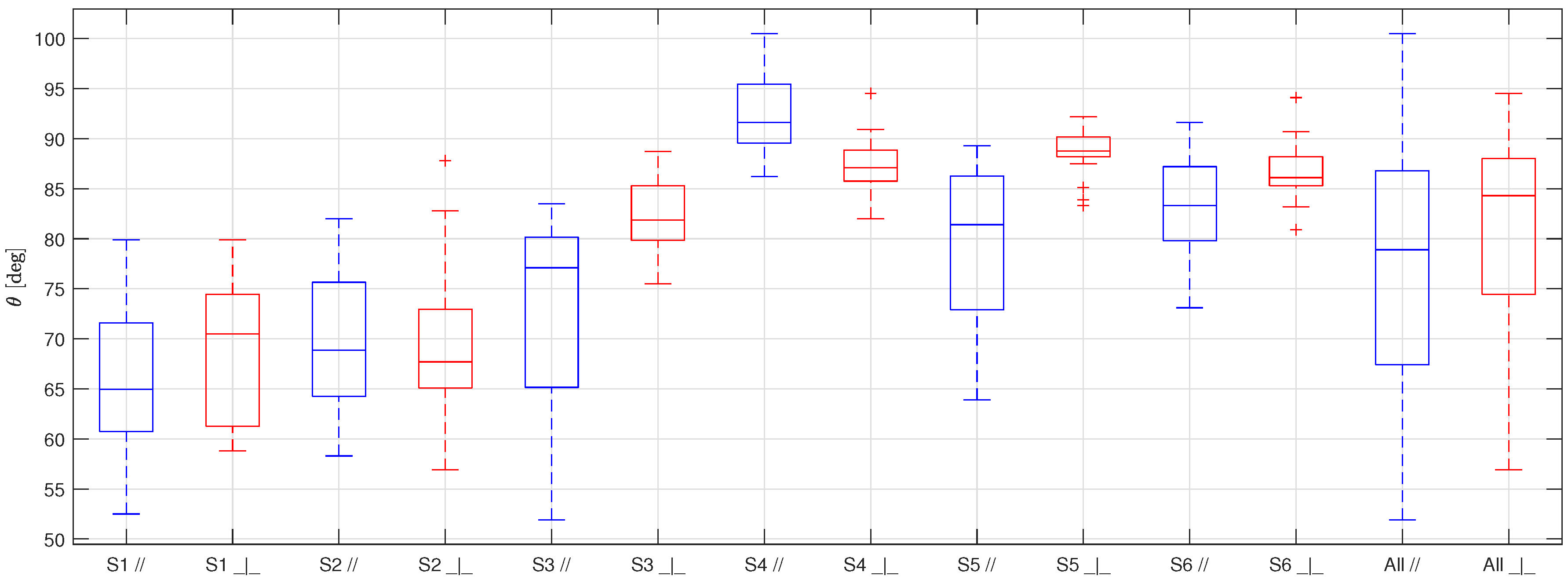
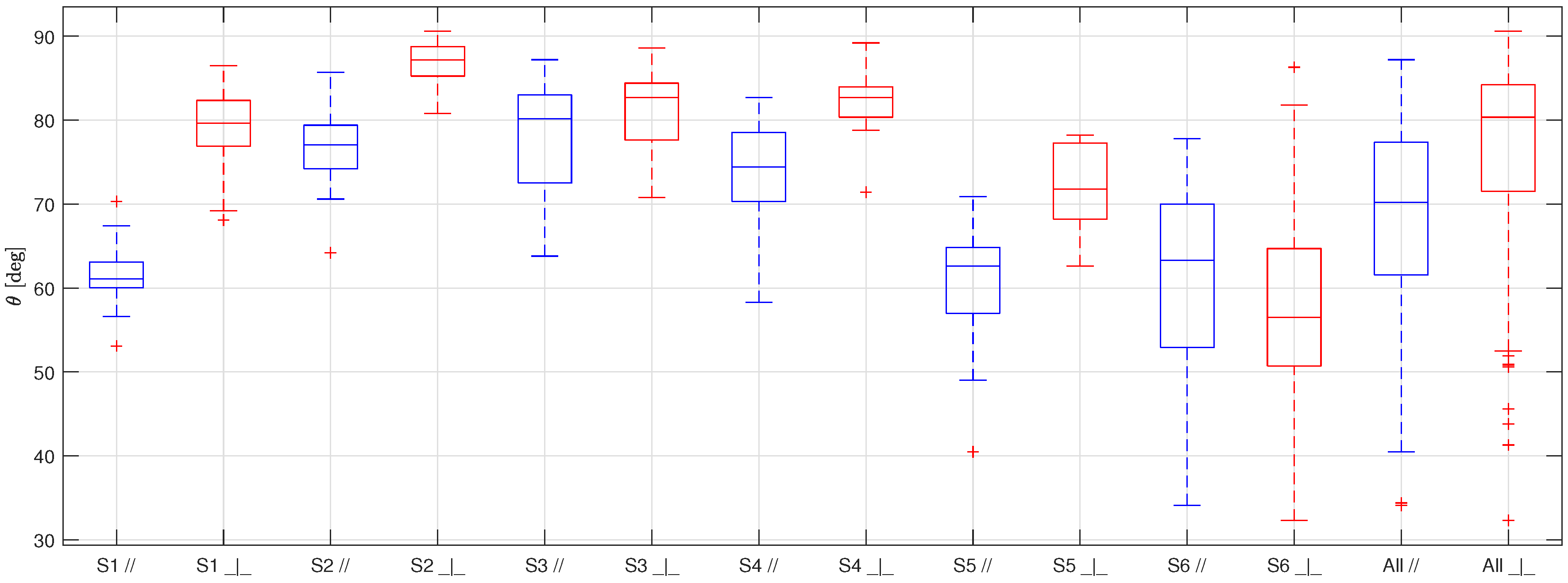
3.1. Static Contact Angle

As previously mentioned, for the static contact angle analysis, six samples for each surface were selected.
As all the surfaces presented micro-grooves due to manufacturing (see Figure 2), the pictures of the drops were taken with the lens of the camera both parallel and perpendicular to the grooves in order to highlight the possible different wetting behavior. Twenty sessile drops were deposited on each sample for each orientation, thus resulting in 240 drops per surface.
The results of the measurement campaign are shown in Figure 5 for HPHI, Figure 6 for STD, and Figure 7 for AL. In these figures, the samples are indicated with the letter S associated with a progressive number from 1 to 6, the symbols / / and _ | _ represent the parallel and perpendicular orientations of the lens with respect to the grooves, respectively, and the overall values obtained for each orientation are indicated with the word A l l .
As usual in boxplots, the interval between the first and third quartiles of the data distribution is represented inside the box and the central line shows the median. The maximum and minimum values of the data distribution, excluding outliers, are represented by the external whiskers, while the red crosses show the outliers, namely, the values at a distance from the first and third quartiles greater than 150 % of the box size.
The first thing to be noticed when looking at Figure 5, Figure 6 and Figure 7 is that the results obtained for each sample of the same surface are very scattered. This behavior is probably due to the non-uniform distribution of the limescale formations over the surfaces (that was made on purpose to replicate the real fouling condition), which leads to a thickness and shape of the limescale residuals which significantly change for different samples of the same material.
Furthermore, as for the clean surfaces [10], the static contact angle obtained with the samples in parallel orientation is always lower than the one obtained in a perpendicular orientation. This effect, which is due to the fact that the drops tend to stretch along the grooves, is not reduced by the presence of limescale, but is, instead, accentuated. This behavior is probably a consequence of how the limescale residuals form on the clean surfaces. The water drops deposited on the clean surfaces during the wetting and drying cycles probably tended to follow the grooves shape, thus forming limescale formations which have the same orientation of the grooves. In addition to this effect, as previously mentioned, the limescale residuals are not uniform along the surfaces. Therefore, this leads to more scattered results and, thus, to a greater difference between the two orientations with respect to that obtained for the clean surfaces.
Table 1 summarizes the results of this analysis, showing the mean static contact angle, the median, and the standard deviation obtained for each material and orientation.
From this table, it is possible to observe that the standard deviation is quite high for all the surfaces, as expected from the scattering of the results, while the mean and the median are quite similar, suggesting that extreme values and outliers do not significantly affect the data distribution moments. Moreover, even if the difference between the two orientations is significant for all the surfaces, it is always lower or equal to the standard deviation. Therefore, it is possible to group the results of each surface, ignoring the orientation of the grooves with respect to the camera lens.
Figure 8 shows the overall results of the static contact angle analysis for all the surfaces, neglecting the grooves orientation, which can be used as input parameters in the modeling of IEC recuperators working in real conditions.
From this figure, it is evident that the HPHI surface is the most wettable, with the lowest static contact angle, followed by the AL surface, which has an intermediate wettability, followed, in turn, by the STD surface, which shows the lowest wettability, that is, the highest contact angle. Therefore, when limescale residuals are present on the IEC system plates, the HPHI surface should lead to the best performance of the recuperator, STD is predicted to be the worst, and AL should show intermediate behavior.
However, it is worth noting that all the surfaces tend to show hydrophilic behavior, with contact angles that are almost always below 90°, so the desired wettable behavior is achieved for all the surfaces also in presence of limescale formations.

3.2. Comparison between Clean and Limescale Surfaces

Following the static contact angle analysis, it is interesting to compare the wettability of clean and fouled surfaces, that is, to understand whether limescale increases or reduces the contact angle.
Figure 9 shows a comparison between the overall results for the contact angles of the clean surfaces [10] and the limescale ones.
From this comparison, it is possible to observe that for two surfaces (HPHI and AL), the contact angle decreases in the presence of limescale, while for the other surface (STD), the contact angle slightly increases. In particular, the HPHI median contact angle is reduced by about 19°, that of STD is increased by about 6°, and that of AL is reduced by about 14°.
This effect is probably due to the fact that the limescale formations present on the STD surface are less uniform and thicker than those on the other surfaces (see Figure 3). Therefore, when a drop is deposed on this surface, it tends to pin on sharp edges [19], showing Cassie–Baxter behavior [21].
Consequently, when the surfaces are not perfectly clean and new, but present limescale formations due to continuous wetting and drying cycles with water injected from the city water supply, the HPHI remains the most wettable surface, while the STD and AL behavior is reversed. In fact, the clean AL surface is less wettable than the clean STD, while in the presence of limescale, AL becomes more wettable than STD.
Therefore, the HPHI coating presents the highest wettability both when clean and with limescale residuals, so HPHI is the most suitable surface for IEC system plates in every condition. Conversely, the STD coating may see a worsening of its performance if the water injected in the system is rich in calcium carbonate and tends to form limescale deposits. Finally, the AL uncoated surface seems less suitable when clean, but its wetting behavior significantly improves in the presence of limescale.
It is worth noting that the static contact angles evaluated in this work were measured when depositing the drops on dry surfaces, and when a drop is deposited on a wet surface, as in the real working conditions of IEC systems, the contact angle changes. However, this does not invalidate the results of this study, as from the qualitative analysis it emerged that the water flow in real operating conditions is in accordance with the quantitative wettability results. In fact, the water tends to form a film on the most wettable surface (HPHI), and a rivulet flow on the less wettable surface (STD). Therefore, the comparison among the surfaces and its practical consequences are still valid in wet conditions.

3.3. Spreading Factor and Reversible Work of Adhesion

The last analysis conducted in this study was evaluation of the spreading factor and reversible work of adhesion, which is summarized in Table 2.
As expected from the contact angle analysis, the HPHI surface shows the highest spreading factor and reversible work of adhesion, followed by the AL surface, followed, in turn, by the STD surface.
Therefore, this analysis confirmed what has previously been highlighted, namely, that the HPHI in the presence of limescale remains the most wettable surface, showing a tendency to form a water film on the plates, the STD surface becomes less wettable in the presence of limescale formations, tending to form single drops or small drop agglomerations which remain separated, and the AL surface shows intermediate behavior. These results also confirmed the observations that emerged from the qualitative analysis.

4. Conclusions

In this study, the wettability of three surfaces used for IEC system plates was analyzed in the presence of limescale formations.
In particular, the static contact angle that water drops form on each surface was measured. The results showed that the aluminum surface covered with a hydrophilic lacquer (HPHI) exhibited the lowest contact angle (median: 50°), followed by the uncoated surface (AL), which had an intermediate contact angle (median: 75°), followed, in turn, by the aluminum surface covered with a standard epoxy coating (STD), which exhibited the highest contact angle (median: 81°).
These results, which can be used as input parameters in models that aim to predict the behavior and performance of IEC recuperators in real operating conditions, were then compared with those obtained for the corresponding clean surfaces [10]. This comparison showed that the HPHI surface is the most wettable, so the most suitable for IEC systems plates, both in clean and limescale conditions. In contrast, the STD wettability is slightly reduced in the presence of limescale, while the wettability of AL improves when the plate presents limescale formations.
This behavior is also evidenced from the evaluation of the spreading factor and reversible work of adhesion. These parameters are the highest for HPHI, which is more likely to form a uniform water film on its surface, they are the lowest for STD, which tends to form separated water drops or small drop agglomerations, and they are intermediate for AL.
These results also confirmed the evidence about the limescale formations that was obtained by visual observation of real IEC plates which had undergone some weeks of real operation.

Author Contributions

Conceptualization, R.C., P.L., L.M. and M.G.; methodology, R.C. and M.G.; resources, P.L. and M.G.; software, R.C. and M.G.; investigation, R.C. and M.G.; formal analysis, R.C. and M.G.; validation, all authors; writing—original draft preparation, R.C.; writing—review and editing, all authors; visualization, R.C. All authors have read and agreed to the published version of the manuscript.

Funding

This research received no external funding.

Data Availability Statement

Data are available from the authors upon reasonable request.

Conflicts of Interest

The three surfaces used for the IEC systems plates, namely, HPHI, STD, and AL, were supplied by Recuperator S.p.A.

Abbreviations

The following abbreviations are used in this manuscript:
ADSAAxisymmetric drop shape analysis
ALAluminum uncoated surface
HPHIAluminum surface coated with a hydrophilic lacquer
IECIndirect evaporative cooling
STDAluminum surface covered with a standard epoxy coating
SSpreading factor
W a Reversible work of adhesion
σ S G Interface energy between the solid surface and the gaseous phase
σ S L Interface energy between the solid surface and the liquid phase
σ L G Interface energy between the liquid and gaseous phases
θ Static contact angle

References

  1. Yang, H.; Shi, W.; Chen, Y.; Min, Y. Research development of indirect evaporative cooling technology: An updated review. Renew. Sustain. Energy Rev. 2021, 145, 111082. [Google Scholar] [CrossRef]
  2. Duan, Z.; Zhan, C.; Zhang, X.; Mustafa, M.; Zhao, X.; Alimohammadisagvand, B.; Hasan, A. Indirect evaporative cooling: Past, present and future potentials. Renew. Sustain. Energy Rev. 2012, 16, 6823–6850. [Google Scholar] [CrossRef]
  3. Amer, O.; Boukhanouf, R.; Ibrahim, H.G. A review of evaporative cooling technologies. Int. J. Environ. Sci. Dev. 2015, 6, 111. [Google Scholar] [CrossRef]
  4. Hussain, I.; Bibi, F.; Bhat, S.A.; Sajjad, U.; Sultan, M.; Ali, H.M.; Azam, M.W.; Kaushal, S.K.; Hussain, S.; Yan, W.M. Evaluating the parameters affecting the direct and indirect evaporative cooling systems. Eng. Anal. Bound. Elem. 2022, 145, 211–223. [Google Scholar] [CrossRef]
  5. Porumb, B.; Ungureşan, P.; Tutunaru, L.F.; Şerban, A.; Bălan, M. A review of indirect evaporative cooling operating conditions and performances. Energy Procedia 2016, 85, 452–460. [Google Scholar] [CrossRef]
  6. Chua, K.; Xu, J.; Cui, X.; Ng, K.; Islam, M. Numerical heat and mass transfer analysis of a cross-flow indirect evaporative cooler with plates and flat tubes. Heat Mass Transf. 2016, 52, 1765–1777. [Google Scholar] [CrossRef]
  7. De Antonellis, S.; Joppolo, C.M.; Liberati, P.; Milani, S.; Romano, F. Modeling and experimental study of an indirect evaporative cooler. Energy Build. 2017, 142, 147–157. [Google Scholar] [CrossRef]
  8. Guilizzoni, M.; Milani, S.; Liberati, P.; De Antonellis, S. Effect of plates coating on performance of an indirect evaporative cooling system. Int. J. Refrig. 2019, 104, 367–375. [Google Scholar] [CrossRef]
  9. Caruana, R.; De Antonellis, S.; Marocco, L.; Guilizzoni, M. Modeling of Indirect Evaporative Cooling Systems: A Review. Fluids 2023, 8, 303. [Google Scholar] [CrossRef]
  10. Caruana, R.; De Antonellis, S.; Marocco, L.; Liberati, P.; Guilizzoni, M. Experimental Characterization of the Wettability of Coated and Uncoated Plates for Indirect Evaporative Cooling Systems. Fluids 2023, 8, 122. [Google Scholar] [CrossRef]
  11. Orkoula, M.G.; Koutsoukos, P.G.; Robin, M.; Vizika, O.; Cuiec, L. Wettability of CaCO3 surfaces. Colloids Surf. A Physicochem. Eng. Asp. 1999, 157, 333–340. [Google Scholar] [CrossRef]
  12. Hu, B.; Fraunholz, N.; Rem, P. Wetting technologies for high-accuracy sink-float separations in water-based media. Open Waste Manag. J. 2010, 3, 71–80. [Google Scholar] [CrossRef]
  13. Jin, H.Q.; Athreya, H.; Wang, S.; Nawaz, K. Experimental study of crystallization fouling by calcium carbonate: Effects of surface structure and material. Desalination 2022, 532, 115754. [Google Scholar] [CrossRef]
  14. Liu, Y.; Jiang, T.; Zhou, Y.; Zhang, Z.; Wang, Z.; Tong, H.; Shen, X.; Wang, Y. Evaluation of the attachment, proliferation, and differentiation of osteoblast on a calcium carbonate coating on titanium surface. Mater. Sci. Eng. C 2011, 31, 1055–1061. [Google Scholar] [CrossRef]
  15. Cruz, M.A.E.; Ruiz, G.C.; Faria, A.N.; Zancanela, D.C.; Pereira, L.S.; Ciancaglini, P.; Ramos, A.P. Calcium carbonate hybrid coating promotes the formation of biomimetic hydroxyapatite on titanium surfaces. Appl. Surf. Sci. 2016, 370, 459–468. [Google Scholar] [CrossRef]
  16. Marmur, A. Soft contact: Measurement and interpretation of contact angles. Soft Matter 2006, 2, 12–17. [Google Scholar] [CrossRef]
  17. Ponomar, M.; Krasnyuk, E.; Butylskii, D.; Nikonenko, V.; Wang, Y.; Jiang, C.; Xu, T.; Pismenskaya, N. Sessile drop method: Critical analysis and optimization for measuring the contact angle of an ion-exchange membrane surface. Membranes 2022, 12, 765. [Google Scholar] [CrossRef]
  18. Tadmor, R. Approaches in wetting phenomena. Soft Matter 2011, 7, 1577–1580. [Google Scholar] [CrossRef]
  19. Tsoumpas, Y.; Dehaeck, S.; Galvagno, M.; Rednikov, A.; Ottevaere, H.; Thiele, U.; Colinet, P. Nonequilibrium Gibbs’ criterion for completely wetting volatile liquids. Langmuir 2014, 30, 11847–11852. [Google Scholar] [CrossRef] [PubMed]
  20. Wenzel, R.N. Resistance of solid surfaces to wetting by water. Ind. Eng. Chem. 1936, 28, 988–994. [Google Scholar] [CrossRef]
  21. Cassie, A.; Baxter, S. Wettability of porous surfaces. Trans. Faraday Soc. 1944, 40, 546–551. [Google Scholar] [CrossRef]
  22. Feng, L.; Zhang, Y.; Xi, J.; Zhu, Y.; Wang, N.; Xia, F.; Jiang, L. Petal effect: A superhydrophobic state with high adhesive force. Langmuir 2008, 24, 4114–4119. [Google Scholar] [CrossRef]
  23. Hejazi, V.; Moghadam, A.D.; Rohatgi, P.; Nosonovsky, M. Beyond Wenzel and Cassie–Baxter: Second-order effects on the wetting of rough surfaces. Langmuir 2014, 30, 9423–9429. [Google Scholar] [CrossRef]
  24. Li, J.; Jing, Z.; Yang, Y.; Wang, Q.; Lei, Z. From Cassie state to Gecko state: A facile hydrothermal process for the fabrication of superhydrophobic surfaces with controlled sliding angles on zinc substrates. Surf. Coat. Technol. 2014, 258, 973–978. [Google Scholar] [CrossRef]
  25. Tadmor, R.; Yadav, P.S. As-placed contact angles for sessile drops. J. Colloid Interface Sci. 2008, 317, 241–246. [Google Scholar] [CrossRef] [PubMed]
  26. Del Rıo, O.; Neumann, A. Axisymmetric drop shape analysis: Computational methods for the measurement of interfacial properties from the shape and dimensions of pendant and sessile drops. J. Colloid Interface Sci. 1997, 196, 136–147. [Google Scholar]
  27. Guilizzoni, M. Drop shape visualization and contact angle measurement on curved surfaces. J. Colloid Interface Sci. 2011, 364, 230–236. [Google Scholar] [CrossRef]
  28. Hoorfar, M.; Neumann, A. Recent progress in axisymmetric drop shape analysis (ADSA). Adv. Colloid Interface Sci. 2006, 121, 25–49. [Google Scholar] [CrossRef]
  29. Guilizzoni, M.; Sapienza, J.; Caruana, R.; Basso Peressut, A.S.; Di Virgilio, M.; Latorrata, S. Wettability of sulfonated graphene oxide membranes for proton exchange membrane fuel cells. Colloids Surf. A Physicochem. Eng. Asp. 2024, 684, 133151. [Google Scholar] [CrossRef]
  30. Zisman, W.A. Relation of the Equilibrium Contact Angle to Liquid and Solid Constitution; ACS Publications: Washington, DC, USA, 1964. [Google Scholar]
  31. Ayyad, A.H. Thermodynamic derivation of the Young–Dupré form equations for the case of two immiscible liquid drops resting on a solid substrate. J. Colloid Interface Sci. 2010, 346, 483–485. [Google Scholar] [CrossRef]
Figure 1. Parts of two IEC systems plates (HPHI on the top and STD on the bottom) after some weeks of operation, with zooms on evident limescale residuals.
Fluids 09 00076 g001
Figure 2. Difference between two flat plates (clean on the left and covered with limescale on the right) of the three surfaces analyzed: HPHI on the top, STD in the middle, and AL on the bottom.
Fluids 09 00076 g002
Figure 3. Enlarged view of samples of the three surfaces analyzed with significant limescale residuals: HPHI on the left, STD in the middle, and AL on the right.
Fluids 09 00076 g003
Figure 4. Examples of sessile drops deposited on the analyzed surfaces: HPHI on the left, STD in the middle, and AL on the right.
Fluids 09 00076 g004
Figure 5. Boxplot representing the static contact angles for the six samples of HPHI covered with limescale (S1, S2, S3, S4, S5, S6), and the overall results (All), obtained taking the pictures with the camera lens parallel to the grooves (in blue) and perpendicular to them (in red).
Fluids 09 00076 g005
Figure 6. Boxplot representing the static contact angles for the six samples of STD covered with limescale (S1, S2, S3, S4, S5, S6), and the overall results (All), obtained taking the pictures with the camera lens parallel to the grooves (in blue) and perpendicular to them (in red).
Fluids 09 00076 g006
Figure 7. Boxplot representing the static contact angles for the six samples of AL covered with limescale (S1, S2, S3, S4, S5, S6), and the overall results (All), obtained taking the pictures with the camera lens parallel to the grooves (in blue) and perpendicular to them (in red).
Fluids 09 00076 g007
Figure 8. Boxplot representing the overall results for the static contact angles on the three analyzed surfaces covered with limescale: HPHI in blue, STD in yellow, AL in grey.
Fluids 09 00076 g008
Figure 9. Boxplot representing a comparison between the overall results for the static contact angles on the three analyzed clean [10] and limescale surfaces: HPHI in blue, STD in yellow, AL in grey.
Fluids 09 00076 g009
Table 1. Results of the static contact angle for the three surfaces and two orientations analyzed.
Material and
Orientation
MeanMedianStandard Deviation
HPHI Parallel45°45°10°
HPHI Perpendicular57°58°12°
STD Parallel77°81°11°
STD Perpendicular79°84°10°
AL Parallel69°70°11°
AL Perpendicular77°80°12°
Table 2. Results of the overall static contact angle median, spreading factor, and reversible work of adhesion for the three surfaces analyzed.
MaterialContact Angle
Median
Spreading FactorReversible Work of
Adhesion
HPHI50° 0.026 J / m 2 0.118 J / m 2
STD81° 0.061 J / m 2 0.083 J / m 2
AL75° 0.053 J / m 2 0.091 J / m 2
Disclaimer/Publisher’s Note: The statements, opinions and data contained in all publications are solely those of the individual author(s) and contributor(s) and not of MDPI and/or the editor(s). MDPI and/or the editor(s) disclaim responsibility for any injury to people or property resulting from any ideas, methods, instructions or products referred to in the content.

