1. Introduction
In recent years, few-mode fiber Bragg grating (FM-FBG) has attracted considerable attention, owing to the advantages of simple structure, flexible operation, versatility, low loss, and low crosstalk [
1]. The FM-FBGs can realize the coupling of the forward propagating mode and the phase-matched backward propagating mode, which are widely used in various applications such as fiber filters [
2], fiber lasers [
3,
4,
5], fiber sensors [
6,
7], mode division multiplexing (MDM) communication systems [
8], and mode converters (MCs) [
9,
10,
11,
12].
As one of the key components in an MDM system, the MCs based on FM-FBG can convert a specific mode into other modes. Traditionally, for a uniform FM-FBG, the mode conversion only occurs between modes with the same azimuthal order. However, when FM-FBG has an asymmetric transverse index profile, the mode can convert into the higher azimuthal order modes [
13,
14]. A high-order vector mode conversion approach was proposed based on asymmetric fiber Bragg grating (AFBG), and the influence of the attenuation coefficient
α on vector mode conversion was also theoretically analyzed, and the maximum conversion efficiency at specific
α was achieved for each vector mode [
15]. Additionally, some experiments on asymmetric FM-FBG were also reported. The strong LP
01 and LP
11 mode coupling was experimentally achieved by Wu et al. [
16] through ultra-violet (UV) illumination on the fiber from one side. Wang et al. [
17] realized the mode conversion of high-order vector mode (including TE
01, TM
01, HE
21, HE
31, and EH
11) based on AFBG. Moreover, Yao et al. [
18] designed experiments to realize high-order excitation modes by a lateral core offset splicing spot (OSS), and mode conversion from LP
01 to LP
01, LP
01 to LP
11, LP
11 to LP
11, LP
11 to LP
21, and LP
11 to LP
21 was demonstrated through UV single-side illumination. With the single-side illumination of UV light, the refractive index modulation profile across the fiber core in FM-FBG could change asymmetrically [
19]. The transverse asymmetry is characterized by the attenuation coefficient
α. Therefore, the determination of the attenuation coefficient
α of FM-FBG is significant for realizing high-order mode conversion. The value of
α was generally obtained by a fit of transverse index profile across the core according to measured transverse index data in the experiment [
20,
21]. However, the scheme mentioned above is relatively complicated.
In this paper, we propose a method to determine the value of α according to the transmission spectrum of FM-FBG combined with coupled mode theory. The values of α and χ were obtained for the FBGs inscribed in the homemade few-mode fiber (FMF) by UV single-side illumination. Based on the obtained α and χ, we calculated the transmission spectra of FM-FBG, which is consistent with the experimental results of FM-FBG. Furthermore, the optimization of α was analyzed under different excitations (LP01 mode, LP11 mode).
2. Simulation and Experiment
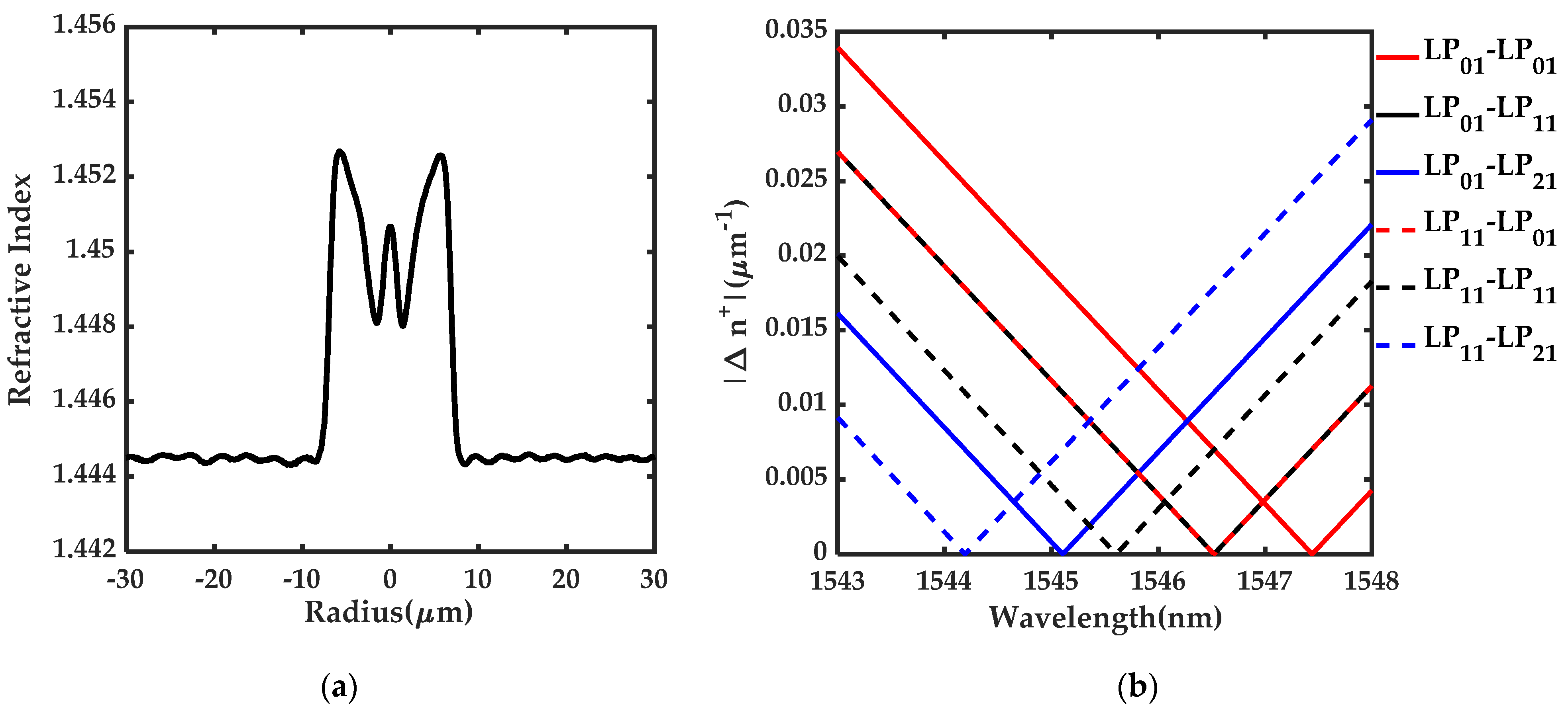
We studied the mode conversion based on asymmetric FBG in a homemade FMF. The homemade FMF was fabricated via modified chemical vapor deposition (MCVD), and its refractive index profile is shown in
Figure 1a. The fiber core diameter was approximately 15 μm, and the max core-cladding index difference was 0.008. The first three linearly polarized modes (LP
01, LP
11, and LP
21 modes) were supported at C band for this FMF. The effective refractive indices of LP
01 mode, LP
11 mode, and LP
21 mode were 1.4495, 1.4477, and 1.4451 at the wavelength of 1550 nm, respectively. Based on the coupled mode theory, strong mode coupling would occur when the phase matching condition was satisfied [
22], expressed as Δn = β
m + β
n − 2K, where β
m and β
n are propagation constants of the
mth forward mode and
nth backward mode. K is the wave number of non-tilted grating, and K = π/∧, where ∧ is the period of grating, and a phase mask with period of 1068 nm is used to inscribe FM-FBG. The variation of Δn
+ with wavelength is shown in
Figure 1b. Among them, the solid lines and the dashed lines indicate that the excitation was LP
01 mode and LP
11 mode, respectively. And the red lines, black lines, and blue lines represent coupled LP
01 mode, LP
11 mode, and LP
21 mode, respectively. The wavelength corresponding to Δn
+ = 0 was the resonance wavelength of the coupled modes. For example, when the excitation was LP
01 mode, the resonance wavelength of the coupled LP
11 mode was 1546.5 nm. The values of resonance wavelength of each coupled mode under different excitation modes are listed in
Table 1. Here, LP
01–LP
01 (LP
11–LP
11) represents the self-coupling (intra-mode coupling) process, and LP
01–LP
11 (LP
01–LP
21, LP
11–LP
01, LP
11–LP
21) represents the cross-coupling (inter-mode coupling) process.
When FM-FBG was fabricated by UV single-side illumination, and the fiber core on the side close to the UV beam had the higher refractive index change because of the absorption of UV light. Therefore, the refractive index profile over the fiber core became asymmetric after UV single-side illumination [
19]. The refractive index modulation is an approximate decreasing exponential profile (as shown in
Figure 2), and the core refractive index modulation function could be expressed as [
15]:
The coupling coefficient
κmn of the
mth and
nth modes can be represented as [
15,
16]:
where
σ(
z) is the slow varying DC perturbation. Here,
σ(
z) = 0.
χ is the grating amplitude, and
α is the attenuation coefficient of the index change distribution.
ϕ(
z) is the chirp function of the grating.
rco is the radius of the fiber core, and Λ is the grating period.
ε0 is the dielectric constant.
ω is the angular frequency of light.
n(
r) is the refractive index of the fiber.
P(
r) is the function on the fiber radius,
r (
P(
r) = 1, inside the perturbed area;
P(
r) = 0, outside the perturbed area). Finally,
Em and
En are the normalized electric fields of the
mth and
nth modes, respectively. Therefore,
α and
χ will affect the mode coupling efficiency by Equation (2).
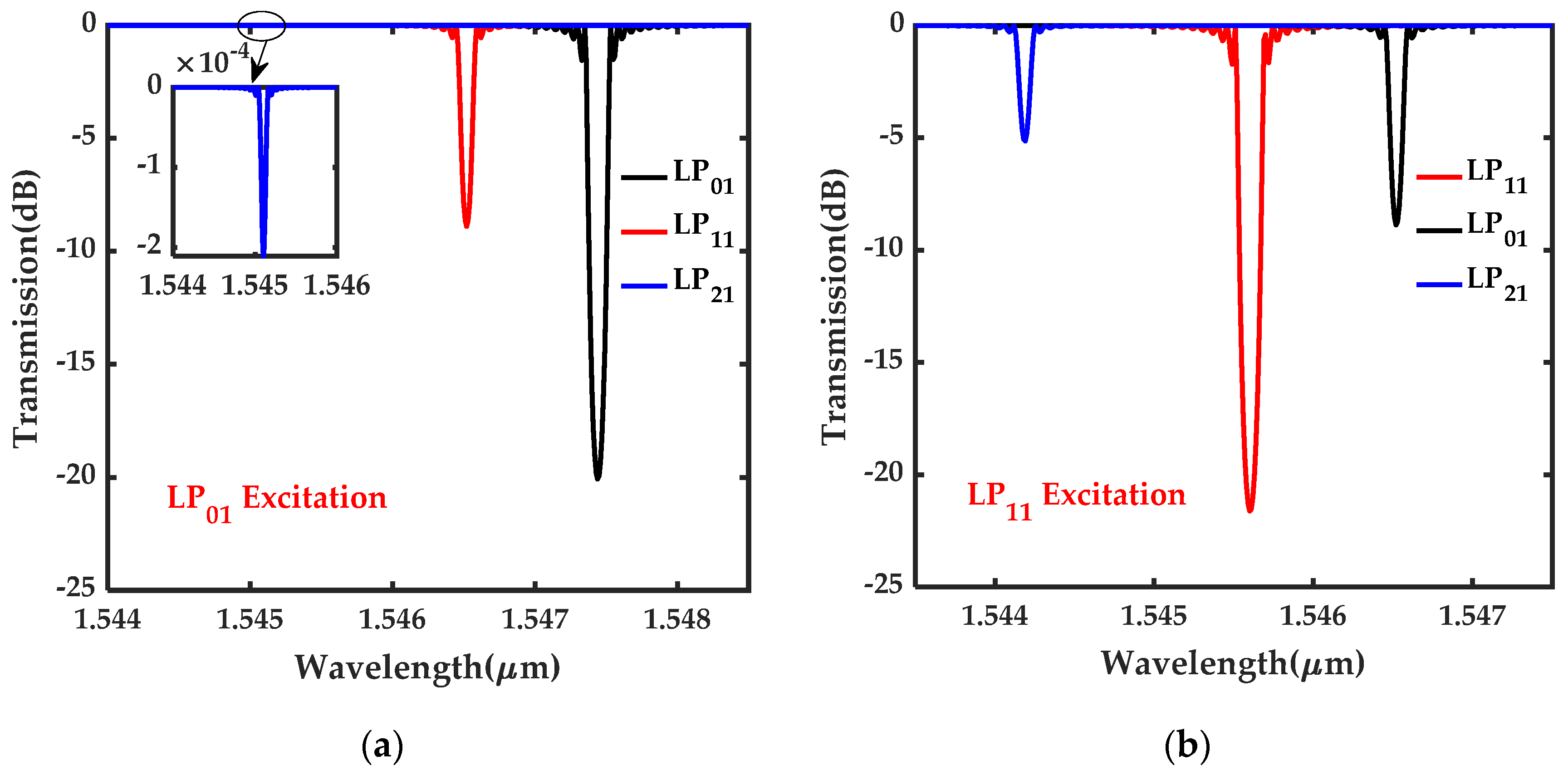
Figure 3a,b show the transmission spectra of the FM-FBG when the excitation (input mode) is LP
01 mode and LP
11 mode, respectively. The black lines, red lines, and blue lines represent the transmission spectra of the coupled LP
01 mode, LP
11 mode, and LP
21 mode, respectively. Here, we adopt
α = 0.2 μm
−1,
χ = 2 × 10
−4, and a grating length L = 13 mm. In
Figure 3a, LP
01 mode was used as the excitation mode, and the transmission peak of LP
01 mode (LP
11 mode) was −20.1 dB (−8.9 dB) at a wavelength of 1.5474 μm (1.5465 μm), which corresponds to conversion efficiency of 99% (87%). However, the transmission of LP
21 mode was very small and can be ignored (as shown in the set in
Figure 3a). LP
11 mode was used as the excitation mode, and the transmission spectrum of the FM-FBG is shown in
Figure 3b. The transmission peaks of LP
01 mode, LP
11 mode, and LP
21 mode were −8.9 dB, −21.6 dB, and −5.1 dB at the wavelengths of 1.5465 μm, 1.5456 μm, and 1.5442 μm, which correspond to conversion efficiencies of 87%, 99.3%, and 69%, respectively. The resonance wavelength corresponding to each coupled mode was consistent with the results in
Table 1. Moreover, compared with the mode conversion from LP
01 mode to LP
21 mode, the mode conversion from LP
11 mode to LP
21 mode was stronger because of the large overlap of the mode fields. Therefore, when the excitation was in LP
11 mode, strong LP
11 and LP
21 mode conversion could be realized. Meanwhile, no matter which mode is used as the excitation, the self-coupling process was stronger than the cross-coupling process.
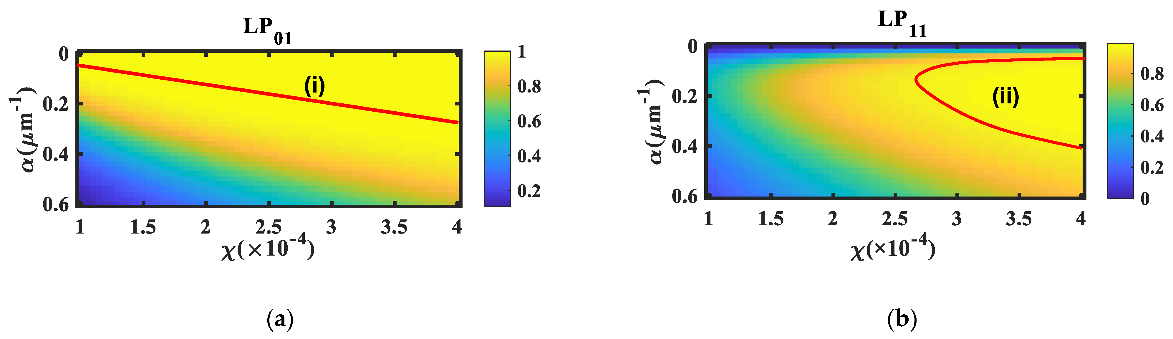
According to the index modulation expression of asymmetric FM-FBG (Equation (1)), the attenuation coefficient
α and the grating amplitude
χ affected the refractive index profile of fiber core and further affected the mode coupling coefficient by Equation (2), and finally determined the output characteristics of the FM-FBG.
α was determined by the absorption factor of the material, and
χ depended on the UV power and the photosensitivity of the fiber [
16]. When the excitation was in LP
01 mode, the variations in the conversion efficiencies of the LP
01 mode and LP
11 mode with
α and
χ are shown in
Figure 4a,b. At a given
α, the conversion efficiencies of the coupled LP
01 mode and LP
11 mode increased with the increase in
χ. Moreover, with a given
χ, as
α increased, the mode conversion efficiency of self-coupling (LP
01–LP
01) decreased, and the mode conversion efficiency of cross-coupling (LP
01–LP
11) increased firstly from zero to the maximum and then decreased. Therefore, with a given
χ, the maximum mode conversion efficiency from the LP
01 mode to the LP
11 mode can be achieved at a specific
α.
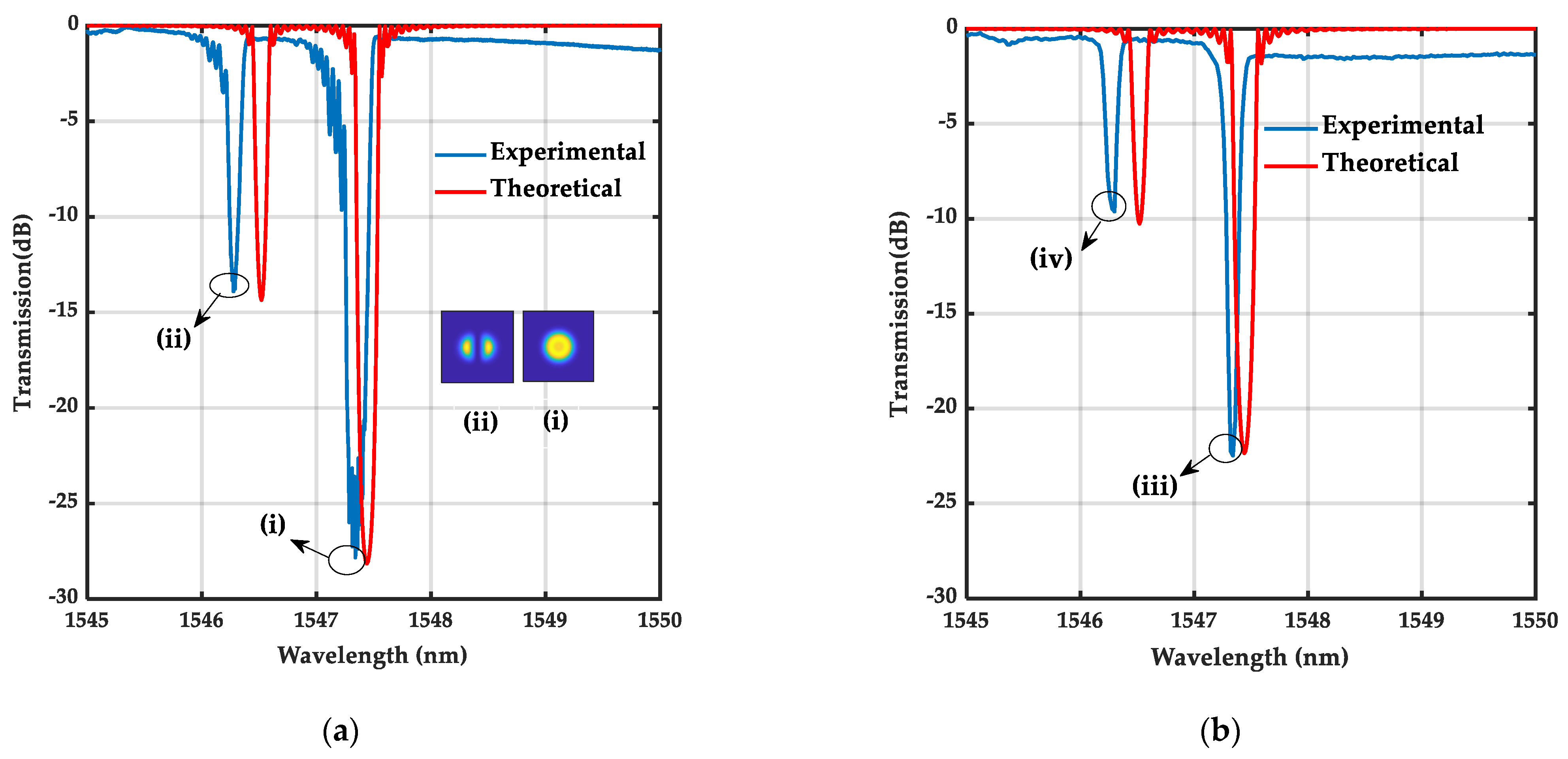
Next, in the experiment, we investigated mode conversion based on asymmetric FM-FBG1, and the FM-FBG1 was written in the homemade FMF by the well-established phase mask method under UV single-side illumination [
16,
23]. The experimental setup included amplified spontaneous emission (ASE) light source, single-mode fiber (SMF), few-mode fiber (FMF), and an optical spectrum analyzer (OSA). The ASE light source enters from SMF to FMF, and then the transmitted light from FMF is output through SMF and the transmission spectrum is monitored by OSA. During splicing of SMF and FMF, the axes of SMF and FMF are aligned without introducing lateral core OSS. Since the homemade FMF supports LP
01, LP
11, and LP
21 modes and does not support LP
02 mode (LP
02 mode is cutoff), it can be determined that the excitation mode in the experiment was LP
01 mode and no other modes were excited [
16]. The length of FM-FBG1 was 13 mm. The values of laser energy, voltage, frequency, and moving speed of the displacement platform were 60 mJ, 19.15 kv, 20 Hz, and 0.2 mm/s, respectively. The experimental results of the transmission spectra of FM-FBG1 are shown as the blue lines in
Figure 5a. The two peaks (i) and (ii) corresponding to self-coupling (LP
01–LP
01) and cross-coupling (LP
01–LP
11) are centered at the wavelengths of 1547.3 nm and 1546.3 nm, respectively. In addition, the values of the transmission peaks (i) and (ii) were –27.8dB and –13.9 dB, which correspond to conversion efficiencies of 99.83% and 95.93%, respectively. The two red lines in
Figure 4a,b show the contour lines of 0.9983 and 0.9593, respectively. According to the intersection point of the two red lines, we obtained
α ≈ 0.2 μm
−1 and
χ ≈ 2.8 × 10
−4.
Then based on the obtained
α and
χ, the theoretical result of transmission spectra is shown as the red lines in
Figure 5a. The values of transmission peak (conversion efficiency) of LP
01–LP
01 and LP
01–LP
11 were −28.1 dB (99.85%) and −14.3 dB (96.28%), respectively. And the resonance wavelengths of these two peaks were 1547.4 nm and 1546.5 nm, respectively. Therefore, the values of the theoretical transmission peak were consistent with the experimental results. Note that the resonance wavelengths of the simulation showed a slight difference from the experimental result, and we believe this difference was caused by the external tension in the processing of fabricating FM-FBG. The external tension would cause the strain change of grating, and the resonance Bragg wavelength shift varied linearly with the strain change [
24,
25]. Since our experiments were operated at room temperature, the effect of temperature was not considered. The Bragg wavelength shift,
, can be expressed as
, where
is the photo-elastic constant (0.22), and
is the strain change of FM-FBG.
is the initial resonance Bragg wavelength. Thus, strain sensitivities were approximately 1.207 pm/microstrain and 1.206 pm/microstrain,
and
,
and
represent the Bragg wavelength shift of the coupled LP
01 and LP
11 modes under LP
01 mode excitation. Therefore, under the external tension, the resonance wavelength will shift linearly. Theoretically
and
should be approximately consistent. However, comparing the experimental and simulation results,
= 0.1 nm and
= 0.2 nm, the resonance Bragg wavelength shift of LP
11 was larger than that of LP
01. This may be due to the non-uniformity of the refractive index profile along the length of the homemade fiber. This non-uniformity will affect the effective refractive indices of LP
01 and LP
11 modes, and result in error of the resonance wavelength shift.
Also, in the experiment, the FM-FBG2 was written in the homemade FMF through UV single-side illumination under LP
01 mode excitation, and the grating length was 10 mm. The experimental result of the transmission spectra of FM-FBG2 is shown as the blue lines in
Figure 5b. The two peaks (iii) and (iv) were centered at the wavelengths of 1547.34 nm and 1546.3 nm, respectively, and the values of the transmission peaks (iii) and (iv) were −22.47 dB and −9.62 dB, which correspond to conversion efficiencies of 99.43% and 89.09%, respectively. Since the parameters of the two experiments are the same except for the grating length,
α and
χ were the same. Based on the obtained
α and
χ, we calculated the transmission spectra of FM-FBG2 (as shown by the red lines in
Figure 5b). The values of the transmission peak (conversion efficiency) of LP
01–LP
01 and LP
01–LP
11 were −22.3 dB (99.41%) and −10.2 dB (90.45%), which are consistent with the experimental results of FM-FBG2. Moreover, the shift of the resonance wavelength of FM-FBG2 was also due to the external tension, which is in accordance with the reason for the FM-FBG1. In addition, comparing the transmission spectra of FM-FBG1 and FM-FBG2, the mode conversion efficiencies increased as the grating length increases.
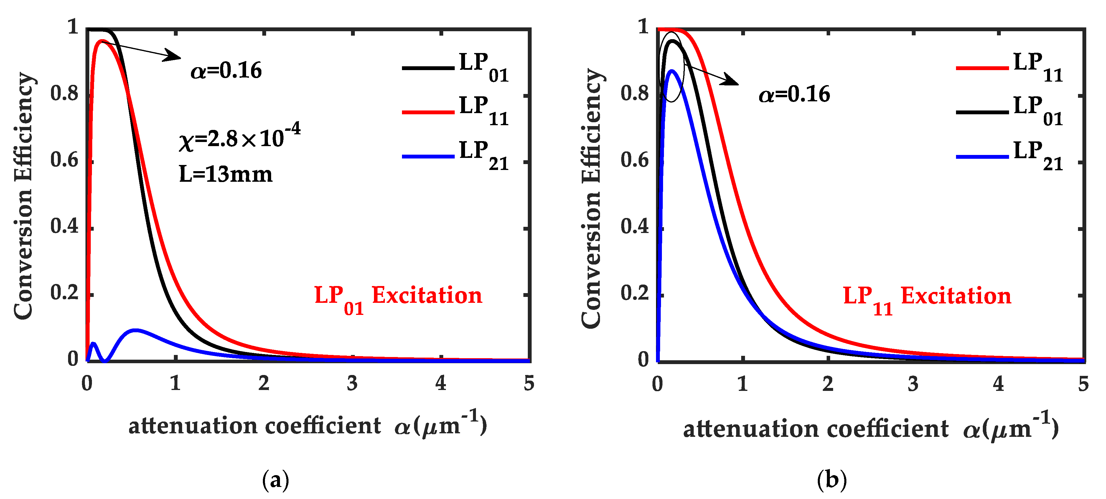
The mode conversion characteristics of FM-FBG1 could be further improved by optimizing
α.
Figure 6a,b show the variations of the mode conversion efficiencies with the attenuation coefficient
α, when excitation was LP
01 mode and LP
11 mode, respectively. The black lines, red lines, and blue lines represent coupled LP
01 mode, LP
11 mode, and LP
21 mode, respectively. When
α = 0, only self-coupling (LP
01–LP
01, LP
11–LP
11) occurs. With the increase of
α, the mode conversion efficiencies of self-coupling gradually decreased. The mode conversion efficiencies of cross-coupling (LP
01–LP
11, LP
11–LP
01, LP
11–LP
21) increased firstly and then decreased with the increase of
α and reached the maximum when
α = 0.16 μm
−1. It should be noted that the FM-FBG inscribed by the phase mask method have the advantages of low cost, simple structure and easy to fabricate. Moreover, the FM-FBG can be applied to MDM optical communication, optical fiber lasers and optical fiber sensors, due to the fact of its mode conversion functions.


