Article

Heating Device Based on Modified Microwave Oven: Improved to Measure Liquid Temperature by Using FBG Sensors

by
Jesus Garavito
1,
Carlos Galvis
1,
Ana Milena López
1,
Arlet Patricia Franco
2,
Francisco Barreiro
1,
Rosa Liliana Tarazona
1 and
Claudia Milena Serpa-Imbett
1,*
1
Grupo de Investigación en Tecnologías Emergentes, Escuela de Ingenierías y Arquitectura, Universidad Pontificia Bolivariana Seccional Montería, Cra 6 no. 97 A 99, Montería 230001, Colombia
2
DANM/Desarrollo y Aplicación de Nuevos Materiales, Escuela de Ingenierías y Arquitectura, Universidad Pontificia Bolivariana Seccional Montería, Cra 6 no. 97 A 99, Montería 230001, Colombia
*
Author to whom correspondence should be addressed.
Photonics 2021, 8(4), 104; https://doi.org/10.3390/photonics8040104
Submission received: 23 February 2021 / Revised: 22 March 2021 / Accepted: 23 March 2021 / Published: 6 April 2021
(This article belongs to the Special Issue Advancements in Fiber Bragg Grating Research)

Abstract

:
A prototype device based on a modified domestic microwave oven for liquid food products pasteurization is presented. This novel design has a coiling glass pipe adapted inside a microwave cavity to allow liquid continuous flow, in which several temperature optical sensors based on Fiber Bragg Grating were installed to measure, by means of contact, the circulating liquid temperature in the pipe, while the oven is on, to obtain the profile temperature as a function of time at different pipe points. The temperatures at liquid input and output were also measured with thermocouples. This device was tested to establish how well it may perform using different standardized liquids with well-known physicochemical and dielectric properties, such as water, water with dissolved sugars, water with dissolved salts, and water with dissolved sugars and salts. It could be observed that the maximum temperature reached was 90 °C for distilled water, 80 °C for water with dissolved salts, 60 °C for water with dissolved sugars and 80 °C for water with dissolved sugars and salts, showing that these data were in agreement with previous results in the literature. This type of device would be potentially useful to establish the device’s efficiency in terms of retention time, energy consumption, and volume of processed liquid, thus, broadening the use of this microwave heating technology with several types of liquid substances.

1. Introduction

Microwaves offer several advantages in thermal food processes when compared to conventional heating methods, due to the volumetric heating resulting in processing time reduction, consequently enhancing quality parameters such as the nutritional value and organoleptic properties of processed products [1,2]. Microwave heating is supported by the ability of any dielectric material to absorb electromagnetic energy and convert a portion of it into thermal energy [3,4,5]. Its performance is characterized by dielectric properties, determining the interaction between electromagnetic waves and the dielectric material. The relative electrical permittivity represents the material ability to polarize and store electric energy in response to an applied electric field, while the dielectric loss factor is associated to energy dissipation as heat [3,4,5].
Due to reported advantages of microwave thermal processing and the high cost of industrial microwave equipment, the modification of domestic microwave ovens is an alternative widely employed for several thermal processes as previously mentioned [6,7]. The more common uses of modified microwave ovens are drying processes [8,9], extraction processes [7,10], pyrolysis processes, [11,12] pasteurization processes, [13,14,15] and others.
Microwave ovens adapted for continuous pasteurization processes have been previously reported. Nonetheless, there is no information about reliable profile temperatures of processed materials because the employed temperature sensor is usually located inside the cavity [16], measuring the oven temperature, which can be different from the processed product temperature. Despite this, successful results have been attained, [13] achieving an effective inactivation of undesirable enzymes and microorganisms in citrus juices [17]. Also, successful results have been reported in enzyme inactivation in orange juice, optimizing the microwave heating conditions in moderate temperatures (60–85 °C). The inactivation kinetics of the target enzymes and microorganisms in microwave processing have been studied for orange juice at temperatures between 55 °C and 70 °C by [18] and apple juice at temperatures between 52.5 °C and 65 °C by [19]. According to the obtained results, non-thermal effects of microwave for enzyme inactivation were suggested.
To carry out the heating process, a novel design of modified microwave device to measure the profile of temperatures of processed product is presented. This consists of temperature optical sensors based on Fiber Bragg Grating, to measure, by means of contact, the temperature of the circulating liquid in the pipe, while the oven is on. The main motivation to use optical fiber is because glass is transparent to the microwave which allows for the measurement of any kind of physical variables inside on a microwave oven [20]. Optical fiber sensors have been used to measure different physical variables to characterize many industrial processes, because they are small, safe and easy to handle since glass does not react to many chemical substances, making it ideal to be used in environments where electronic sensors can be dangerous or contaminant, e.g., in the food industry [21]. On the other hand, optical fiber sensors can be used to measure different kind of physical variables such as strain [22], flow [23], and pH [24,25]. Thus, the modified microwave oven proposed here could be adapted with other optical fibers, or photonic devices to measure other possible physical variables beyond this application. This paper presents two sections: materials and methods in which modifications on the microwave and glass pipe design, temperature monitoring, and validation system are described, followed by a results section in which the device assembly and experimental measurement on the modified microwave oven are presented. It can be seen that this device could be used for heating several kinds of liquid substances.

2. Materials and Methods

Figure 1 shows a prototype device of sterilization or pasteurization of liquids through heating based on a modified microwave oven, in which there is a glass pipe inside, in coiling form, adapted to allow the continuous flow of liquids.
The assembled device is shown in Figure 1, built with elements labelled from A to E. This was provided by a liquid container (A), from which the liquid was pumped through a control flow system (B) to change the flow and holdback of liquid going round into the coiling glass, in which FBG sensors (D) are located, specifically inside a modified microwave oven (C). The microwave oven power and its time were changed with a manual knob for the circulating liquid to reach a specific temperature, directly measured inside the coiling glass through optical fiber temperature sensors when in contact with the liquid. Finally, the liquid exited to a storage container (E). Both containers were provided by thermocouple sensors to measure input and output temperatures of the processed liquid. Thermocouples and optical fiber sensors were installed to be in contact with the liquid to obtain a temperature profile of the liquid in real time, during the process.
This device was built by modifying a commercial microwave oven. Those modifications consisted of making some small holes to allow the input and output of liquids circulate by means of an adapted glass located inside it. This was provided by a temperature monitoring system using both thermocouples and optical fiber temperature sensors. Finally, it was assembled with liquid containers, and a control flow system to perform a controlled heating process into the microwave oven. Both the temperature sensor and control flow systems were operated with independent Labview interfaces. Descriptions of each performance are described as follows.

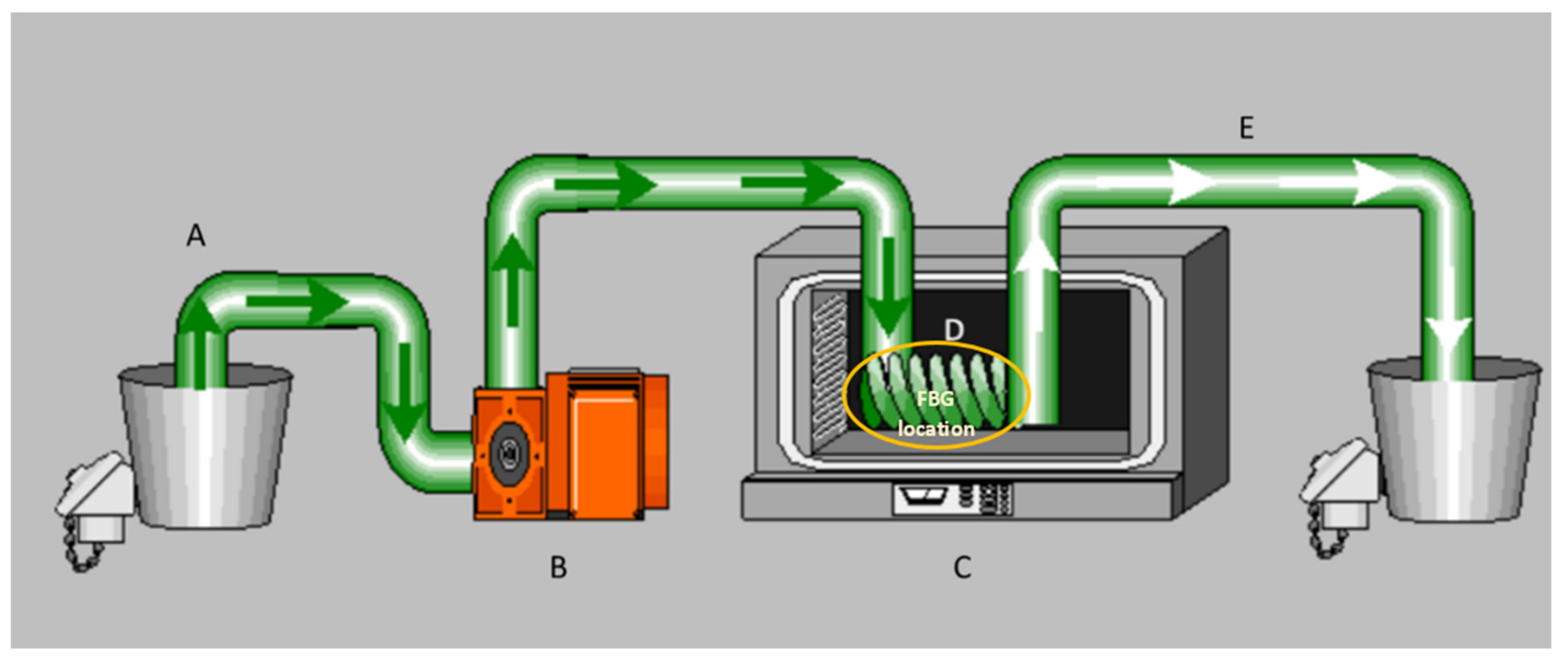
2.1. Modifications on the Microwave

As a first step, a commercial microwave oven reference AS HM-1.1 GRILL Inox was selected to be modified with holes to allow input and output (A and E in Figure 1) of liquid from the pipes. Some holes were made on the top of the microwave oven as further as possible with respect to the position of the magnetron to avoid radiation leak outside, as shown in Figure 2.
Hole diameters were smaller than one quarter of wavelength (λ/4 ≈ 3 cm), being λ = 12.236 cm, corresponding to 2.45 GHz, the operation frequency of the commercial microwave oven selected to assemble the prototype device. These holes allowed the expansion of the inner cooling pipe (D in Figure 1) to the outside.

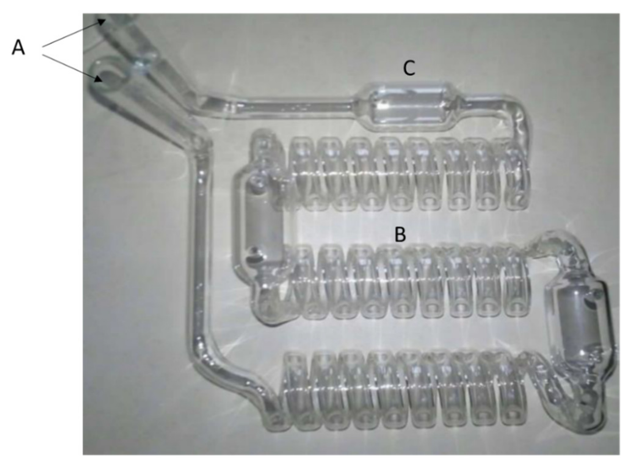
2.2. Coiling Glass Pipe Design

A pipe in coiling form was fabricated in glass since this material is transparent to microwave radiation (see Figure 3). We chose a diameter below depth wavelength of water, which can be heated by electromagnetic energy coming from microwaves, thus allowing for the activation of molecular mechanisms such as molecular friction, dipolar, rotation, and ionic conductivity as a response of polar substances to an alternating electromagnetic field inside the microwave oven, and responsible for heating the substances.
The pipe shown in Figure 3 was installed into the microwave oven cavity. A glass pipe with this kind of coiling allows liquid to circulate through agitation, rapidly and uniformly induced by convection. On the other hand, coiling design increases the volume and liquid hold. Furthermore, this design has bulbs used to install optical temperature fiber sensors to measure liquid temperature along the pipe. Bulb-shaped design was chosen to facilitate the FBG sensors installation to avoid bends and possible breaks if FBG sensors would have been inserted from input or output holes (see A in Figure 3). To facilitate the interaction process between matter (liquid) and energy (microwave radiation), proportional to the power of wave electromagnetic at the operation frequency of 2.45 GHz, the entire glass structure was fabricated, with a diameter close to the penetration depth of 22.7 mm of the electromagnetic wave in the microwave region, considering the features of a highly aqueous medium.
The glass pipe structure was installed into the microwave oven as shown in Figure 4. Also, optical fiber temperature sensors fabricated along the same strand of optical fiber were installed along the pipe, each inside the bulbs, through two holes of 3 mm of diameter approximately as shown in Figure 4b.

2.3. Temperature Monitoring System Based on Optical Fiber Sensors and Thermocouples

The next paragraphs describe the elements and process to assemble the temperature monitoring system based on optical fiber sensors and thermocouples. This consists of temperature optical fiber sensors installed inside a glass pipe structure, a light detection system (interrogator) to transduce wavelength change in fiber sensor to measure temperature, and finally the measurement system based on thermocouples.

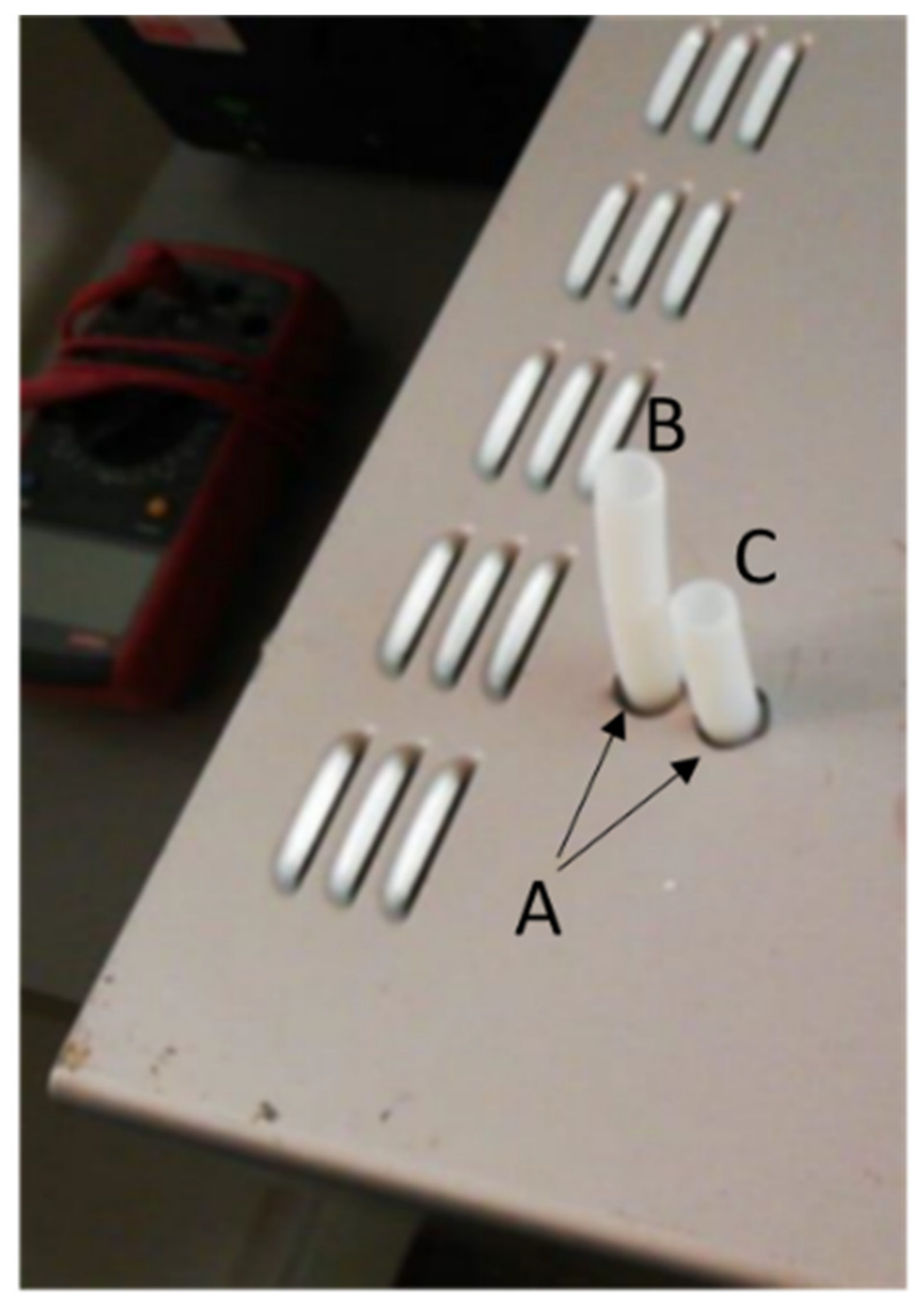
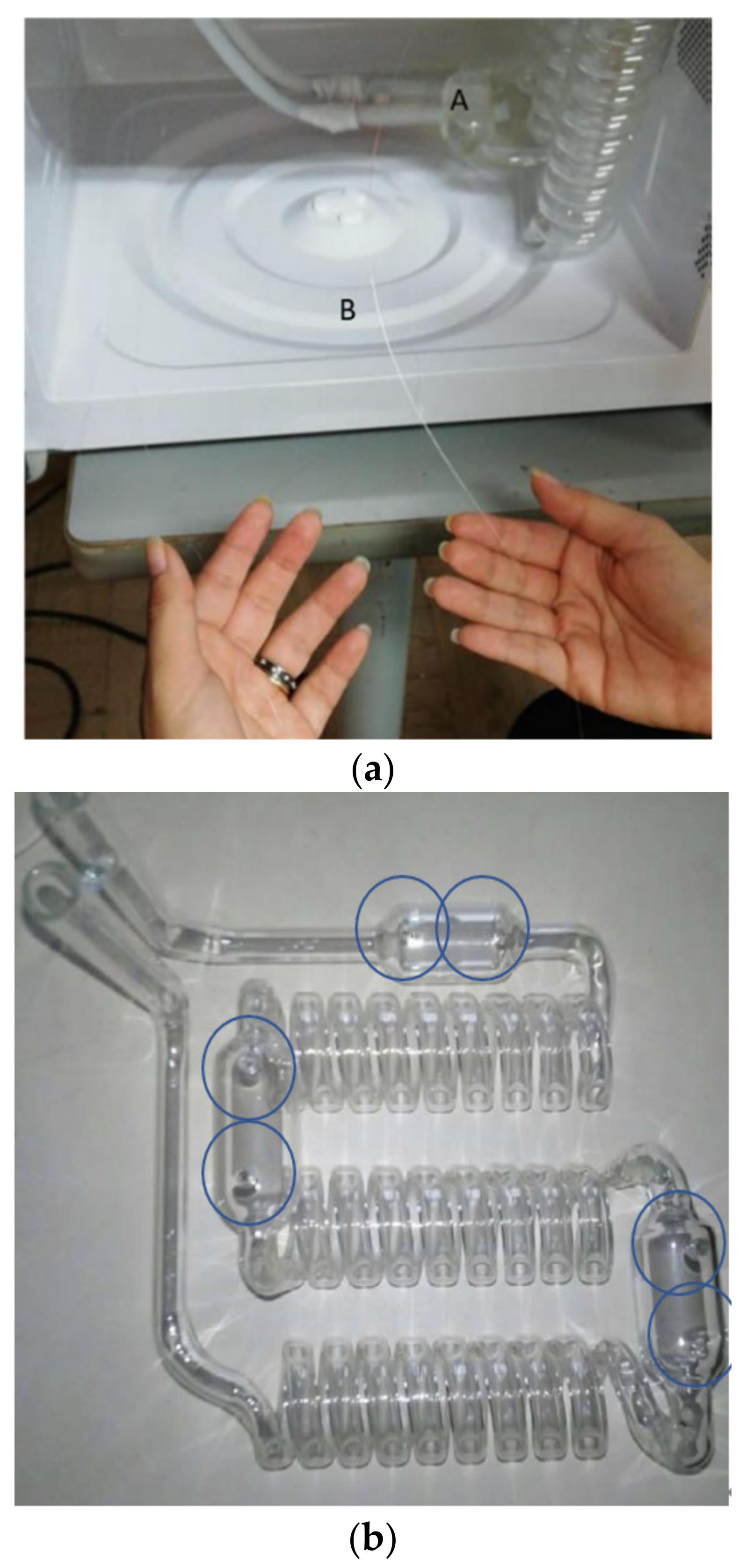
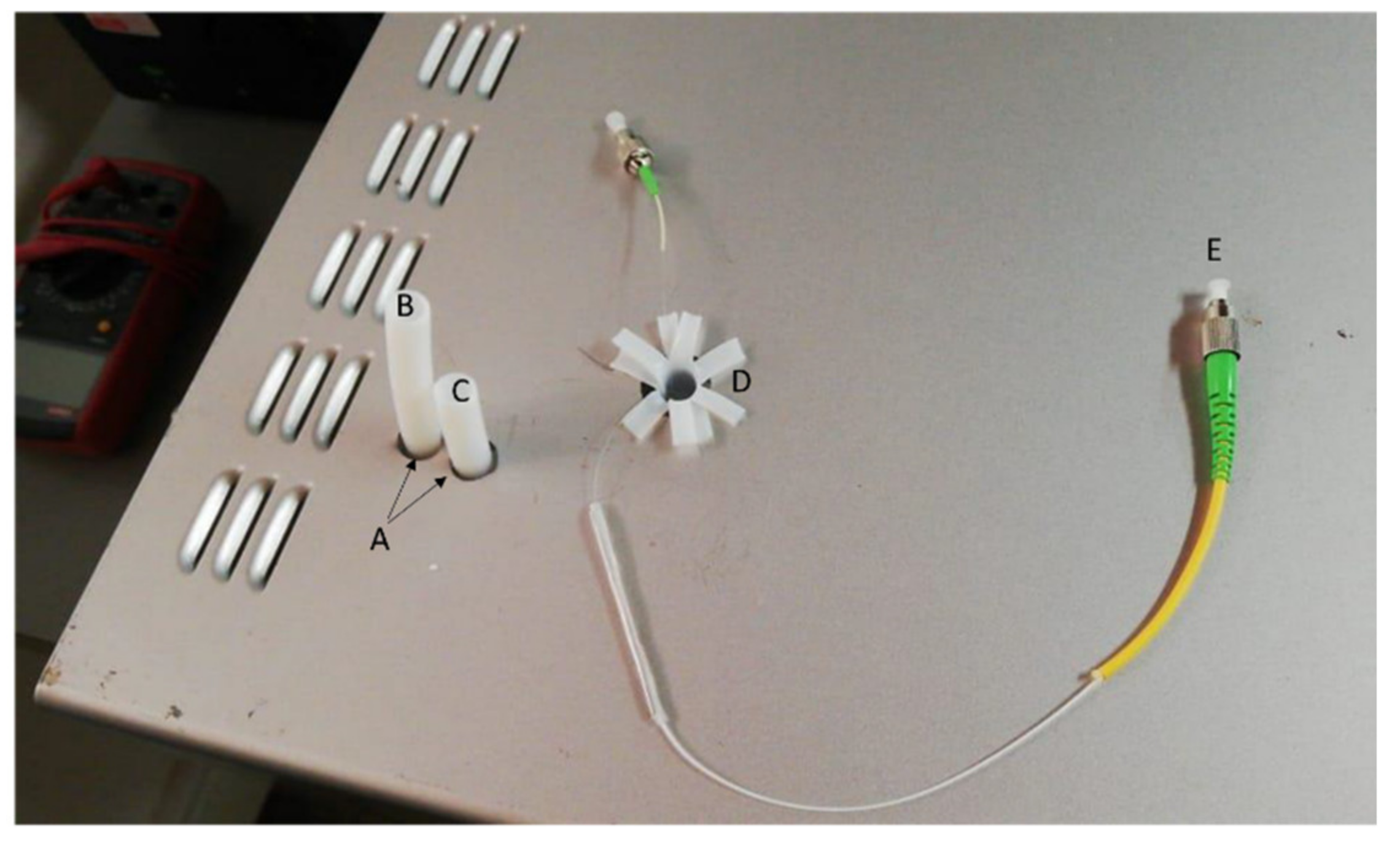
2.3.1. Installation of Temperature Optical Fiber Sensors

Optical fiber sensors were installed inside the glass pipe structure located on the bulbs through two small holes slightly larger than an optical fiber diameter (125 µm) to allow for the crossing of optical fiber, and thus, be in contact with the liquid. Holes were stamped by using acrylic bound to avoid liquid leak (see Figure 4b). Then, a small hole was made on the top of the microwave oven (D) as shown in Figure 5, with a buffer protection to allow the exit of optical fiber connectors (E) that send light toward the detection system.
In this set up, optical fiber temperature sensors elaborated in glass, and based on Bragg Grating technology, widely known as FBG (Fiber Bragg Grating) were used. These kinds of optical fibers can be used as sensors, and they are totally passive and do not require external electric power. FBGs are manufactured from a longitudinal periodic modification of the refractive index of the core into the optical fiber that allows partial portions of light to be reflected at Bragg wavelength [20]. These types of fibers operate as thermal and deformation transducers, with an approximate sensitivity in terms of wavelength of 13 pm/°C, in the case of changes in temperature. Reading of these changes can be measured by direct reading of the Bragg wavelength using spectral analyzers, or by optical filtering techniques that are less expensive and integrated, being ideal for industrial applications.

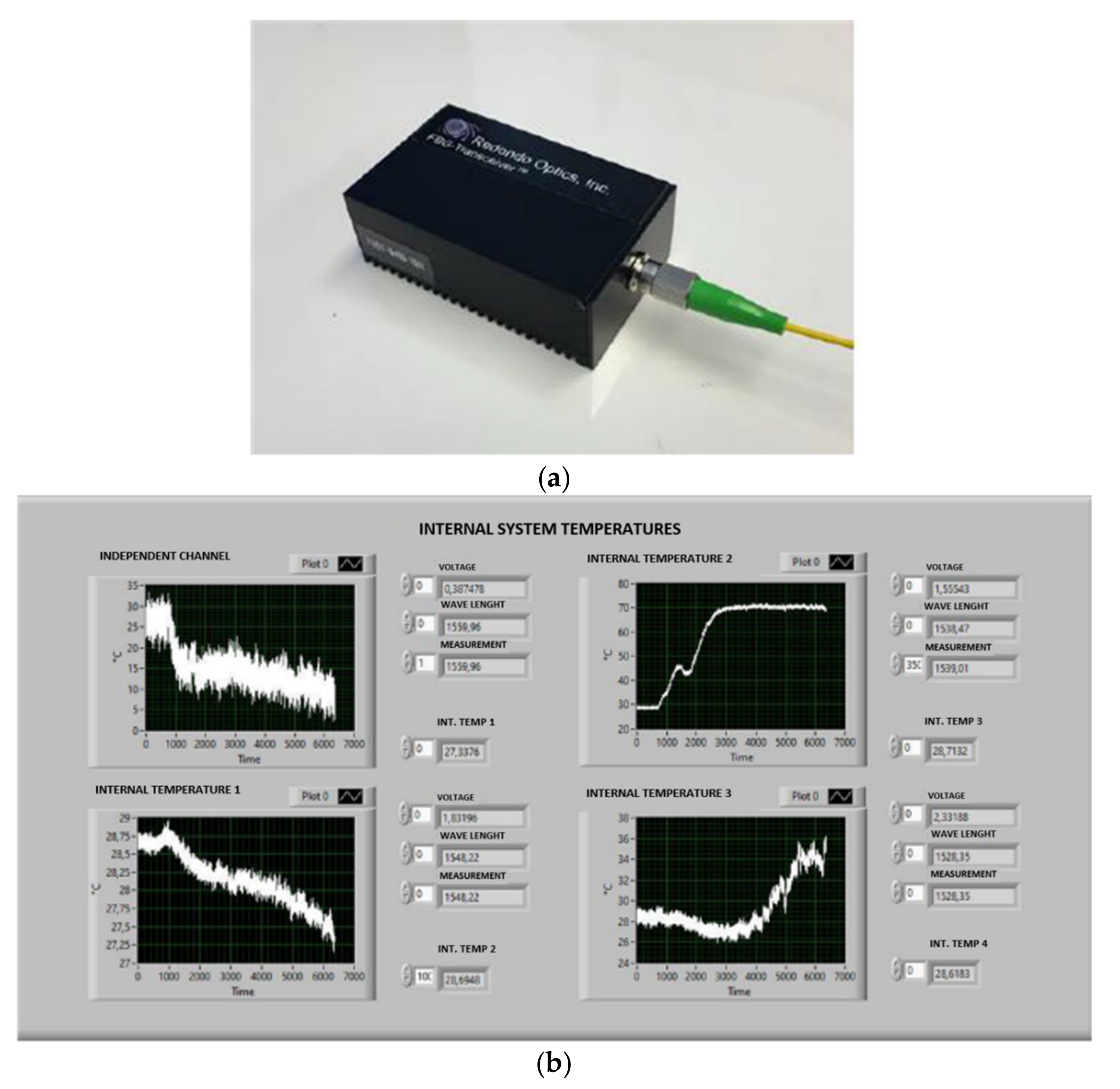
2.3.2. Interrogating System to Measure Temperature Using FBG Temperature Sensor

A device to detect Bragg wavelength changes of the FBG temperature sensor well-known as an interrogator was used in this temperature monitoring system. Then, the temperature was computed by using the typical FBG sensitivity of 13 pm/°C. This interrogator uses a detection technology by optical filtering operated with a resolution of tenths of degrees Celsius. Figure 6a shows the FBG interrogator unit used in this assembled device, connected to an optical fiber FC connector (E in Figure 5). This interrogator miniature FBGT-400-X manufactured by Redondo Optics Inc., was previously calibrated with a procedure suggested by the manufacturer, and operated for temperature detection.
A graphical interface was designed (see Figure 6b) to visualize data in real time, to display temperature data as time function. Four (4) FBG temperature sensors were used, with three of them installed inside the pipe glass, in contact with the liquid, and the other installed inside the microwave cavity. However, there is no limitation, at least from the spatial point of view for the installation of as many optical fiber sensors as possible, if the reading can be performed with the appropriated interrogation system to support many FBG sensors with adequate resolution. This depends on interrogation technique, wavelength spacing between FBGs and Full Width at Half Maximum (FWHM) of FBGs, i.e., how many FBG sensors can be spatially located inside a source spectrum, considering the FBG performance and measuring range. Measurement features are given by interrogation techniques which can be by spectral detection, or by power detection using optical filters. Spectral detection is more accurate but expensive if FBG sensors used are a few, i.e., they become unattractive for small industrial applications [21]. Improvements in performance and interrogation technology, along with a decrease in price, have helped this technology to be attractive in terms of cost. One of the interrogation technologies is based on filtering techniques, even though is limited by the feature of the light source to indirectly read the wavelength shifting in FBG sensors which is less expensive than the spectral detection.

2.3.3. System to Measure Temperature of Liquids on Containers (Input and Output of Liquid)

This system employed a thermocouples sensor RTD PT100 set up with a National Instrument data Acquisition Unit (cDAQ9174), and a transmitter PR6333A of two channel that becomes voltage signal into standard current signal from 4 up to 20 mA. Moreover, a Labview interface was developed to visualize the temperature data as Celsius degrees.

2.3.4. System Validation

The heating performance of the microwave oven was assessed by processing substances with known composition and dielectric properties, such as distilled water, sugars and salts solutions. The dielectric behavior of these substances was previously studied by [5] to evaluate the effect of composition on dielectric properties of green coconut water and predict its heating performance under microwave energy. Salt and sugar solutions were prepared according to [26].

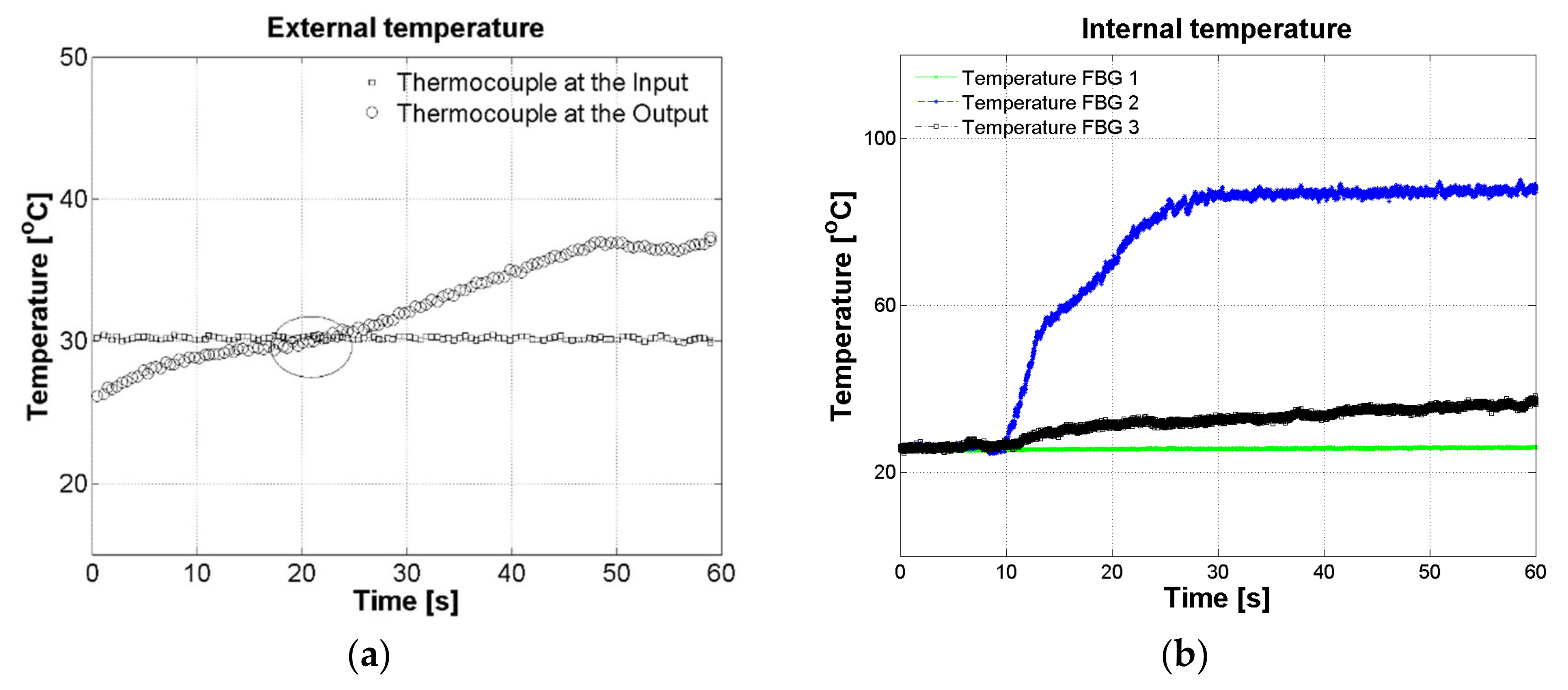
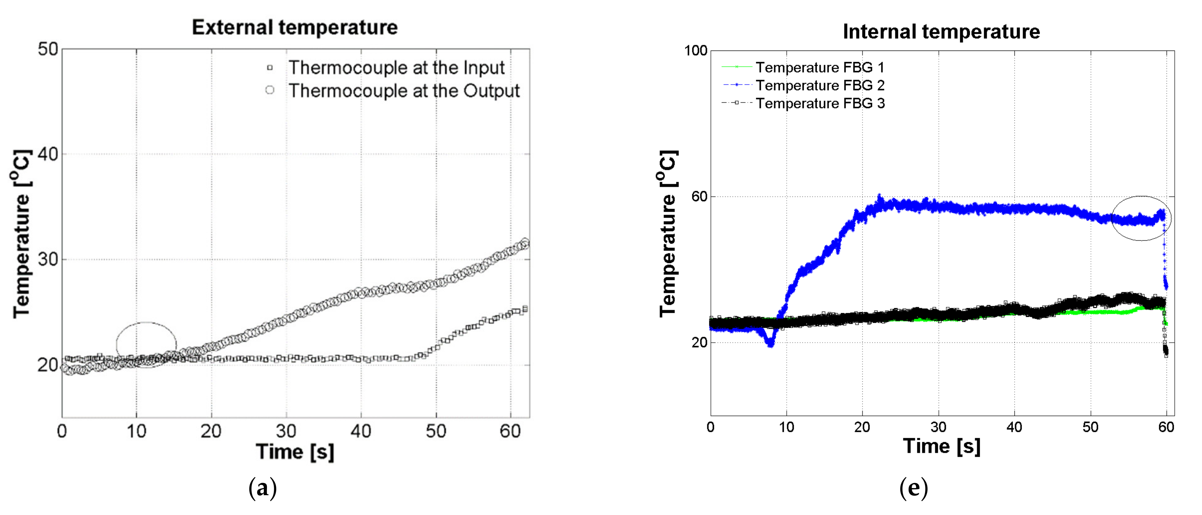
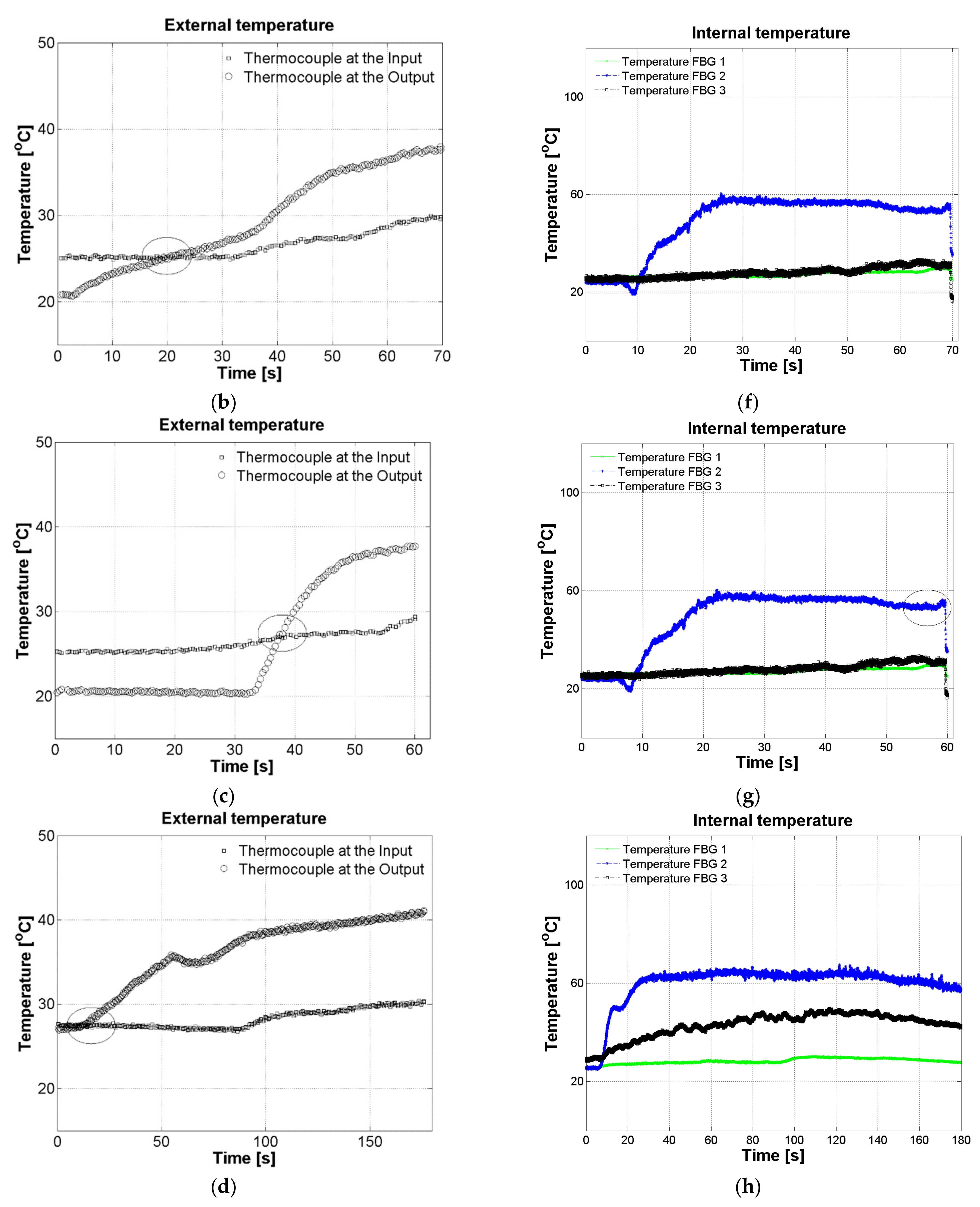
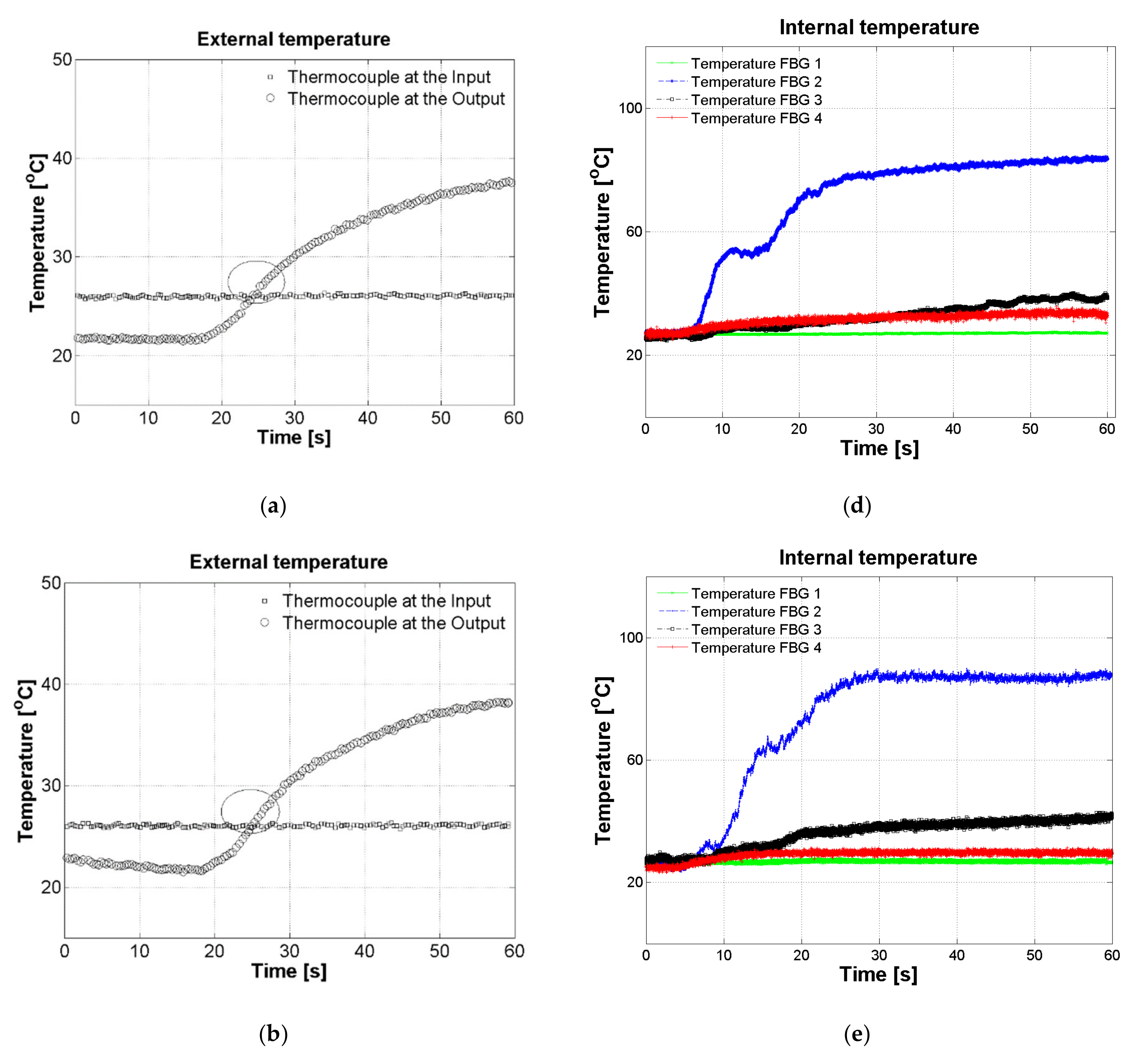
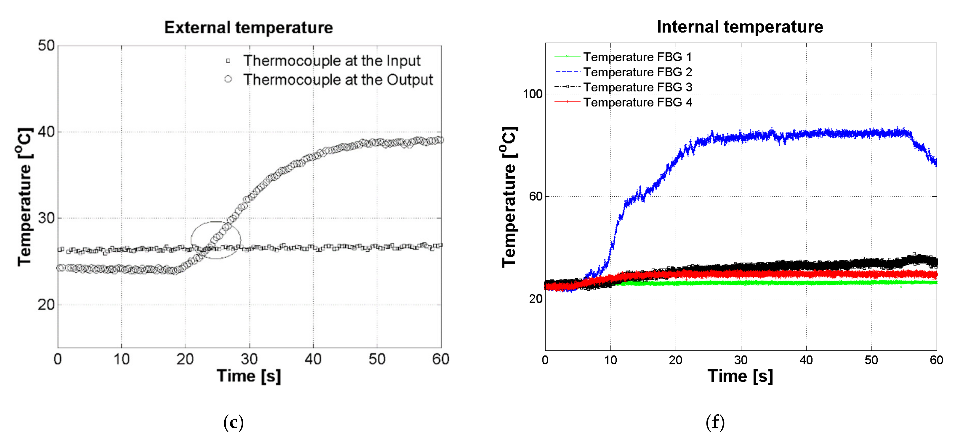
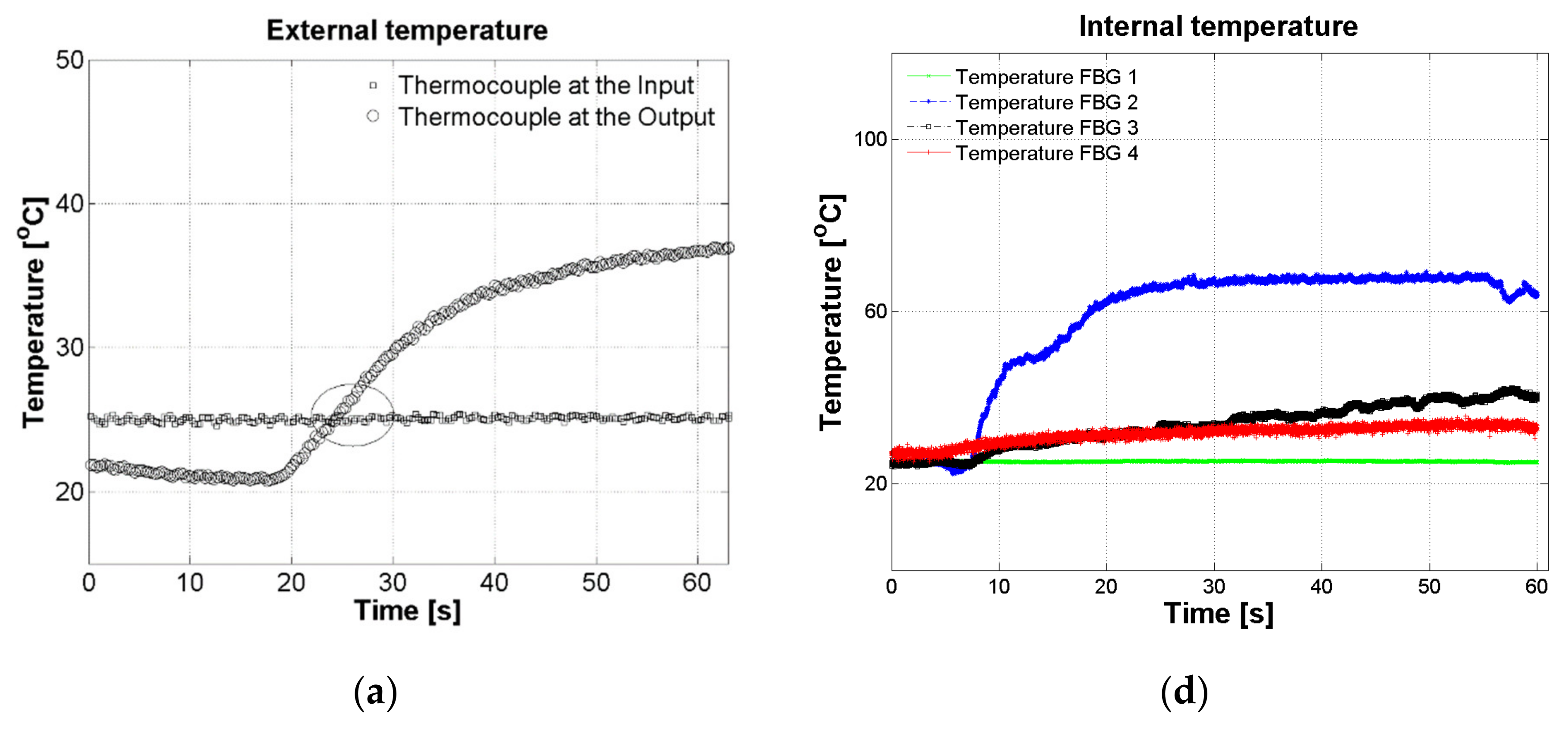
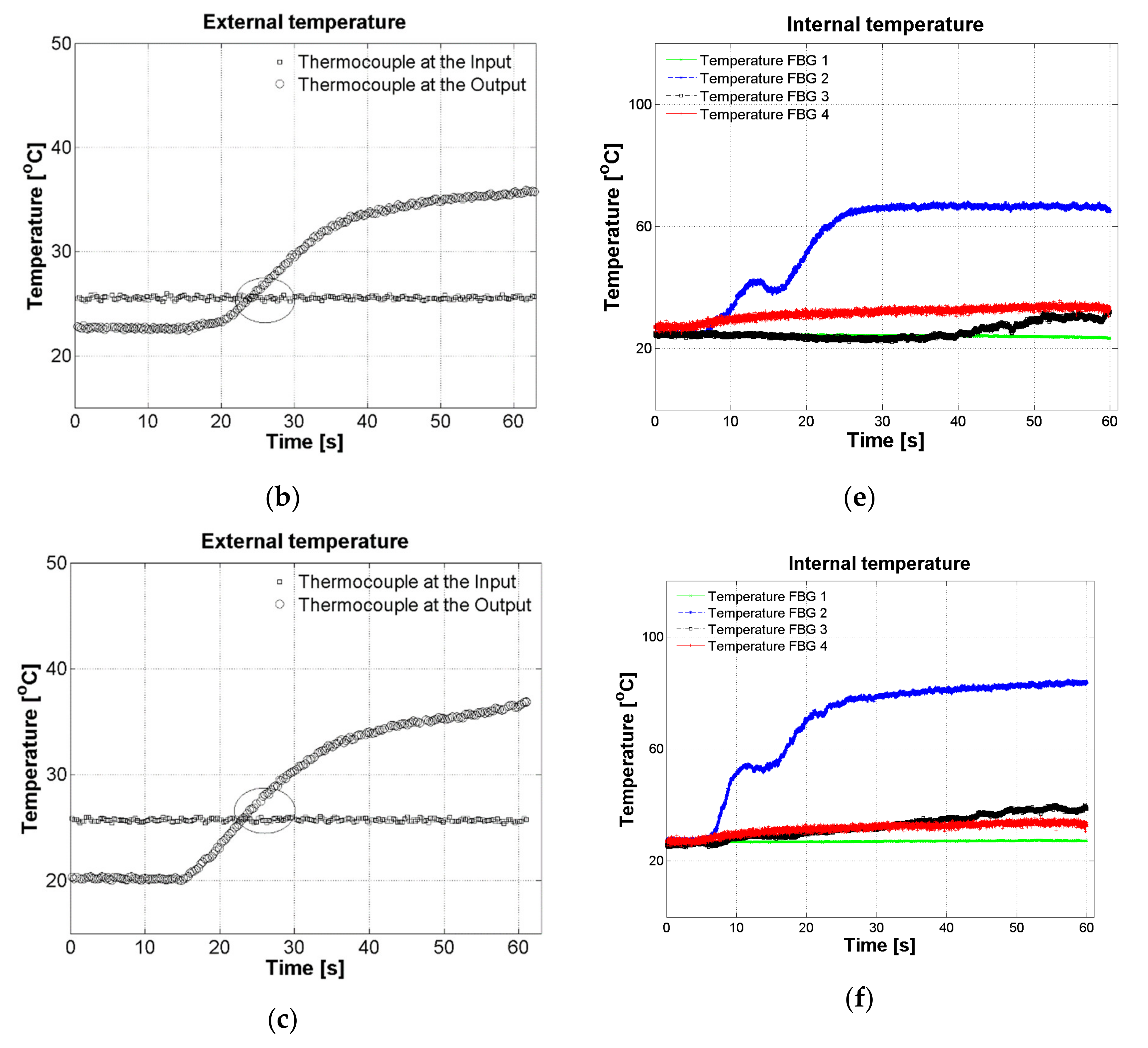
3. Results and Discussion

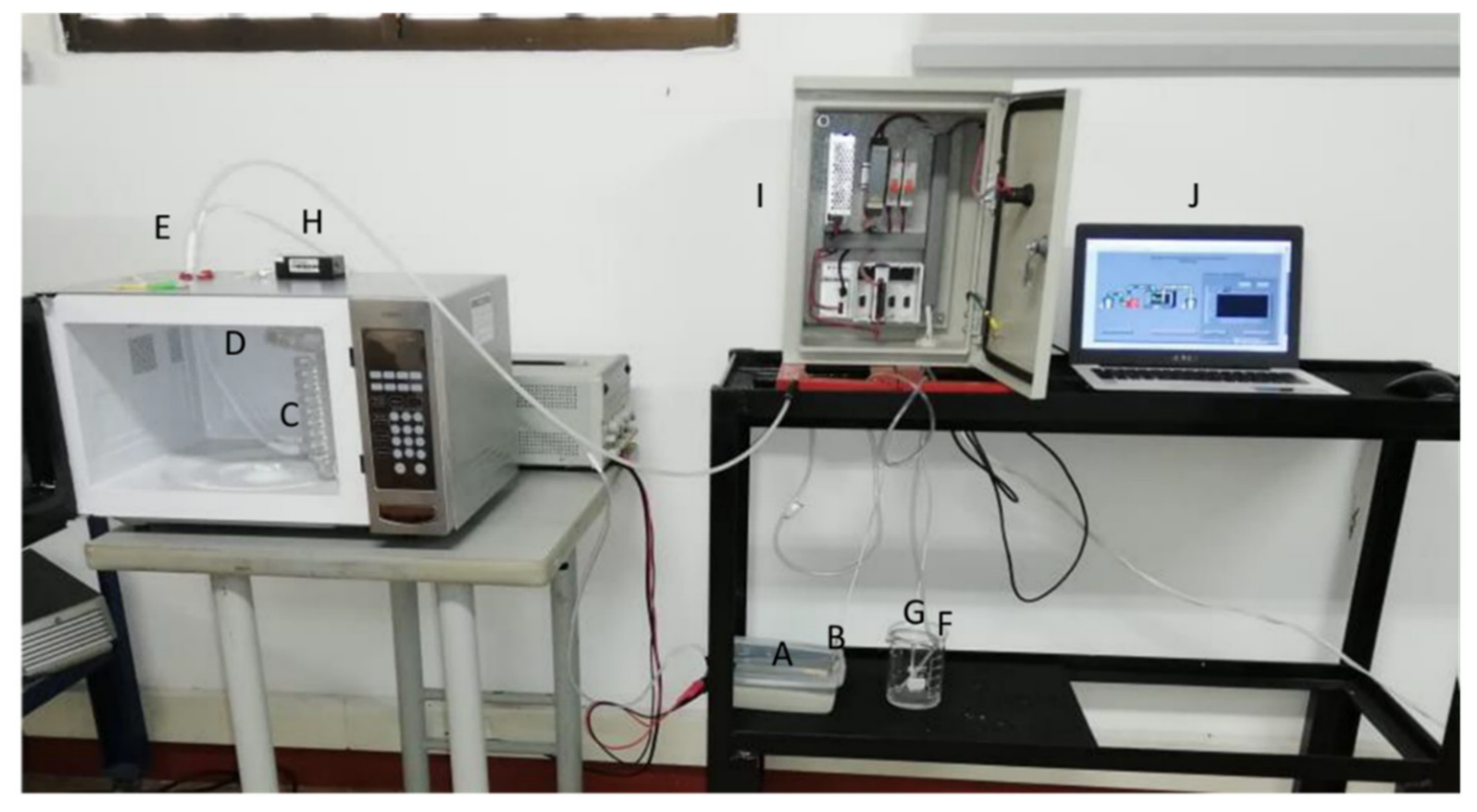
3.1. Assembly of the Device

After assembling each one of the elements, the final device for heating liquids was obtained, as shown in Figure 7. As can be seen, each element has been labelled. This consists of a container (A) that initially holds a certain volume of liquid in contact with a thermocouple (B) and a pipe to carry out liquid to the glass coiling pipe (C) inside to the modified microwave oven through a pump controlled by a flow sensor. The pump offers the possibility of changing the liquid retention time inside the pipe from 30 to 180 s. The liquid circulating through the glass coiling pipe suffers agitation, and therefore is heated in a shorter time, induced by the convention phenomenon. Once the liquid fills the glass coiling pipe, this comes into contact with the FBG temperature sensors installed inside the glass (D). FBG temperature sensors could be installed anywhere in the glass (coiling and straight zones) for monitoring temperature changes during the process through an interrogator (H), thus allowing to get a thermal profile, in real time, since the microwave oven is turned on. Finally, the liquid comes to another container (E) that stores the liquid processed by the microwave oven. This is also equipped with a temperature sensor (G, thermocouple), similar as at the entrance. All temperature sensors: FBG-based and thermocouples are controlled by an interface (I) and set up with a visualization system (J) that displays data as a time function.
This novel design offers the possibility to measure the liquid temperature during the process, establish the device efficiency in terms of retention time, consumed energy, and volume of processed liquid.

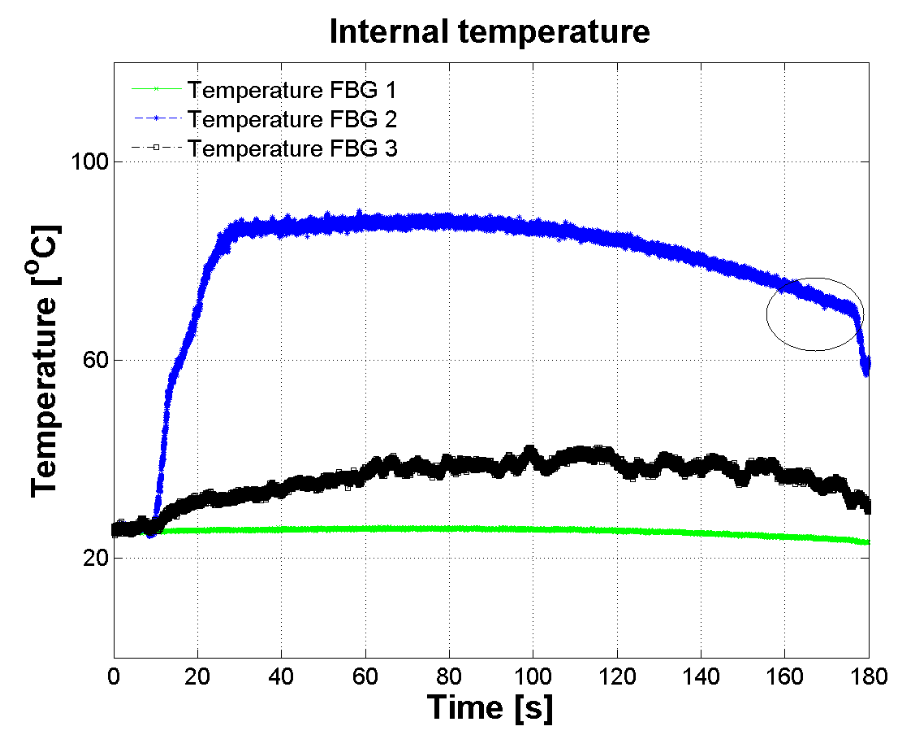
3.2. Temperature Measurement Using the Assembled Prototype

First, the modified microwave oven AS HM-1.1 GRILL Inox was turned on with the maximum power (1000 W) adjusting its time. Simultaneously, the controller interfaces for both FBG temperature sensors and thermocouples were turned on to the temperature data acquisition as a function of time. Then, the glass coiling pipe was filled with the liquid, and the FBG temperature sensors came into contact with the liquid. This device allowed temperature monitoring in at least six points; three of them located inside the glass coiling pipe (C, on the bulbs) as FBG temperature sensors (FBG 2, FBG 3, FBG 4) at Bragg wavelengths of 1559.983 nm, 1548.225 nm, 1538.470 nm, respectively, and the other located outside the glass coiling, but inside the microwave (FBG 1) at a Bragg wavelength of 1528.356 nm. Furthermore, two thermocouples were installed inside the liquid containers (A, F). Standardized liquids such as distilled water, water with dissolved sugars, water with dissolved salts and water with dissolved sugars and salts were used to be heated using this device. Physicochemical properties of these liquids are well-known, specifically, the maximum temperature reached under heating. Thus, these were the reference liquids to test the well-performance of the device in terms of reference temperature. Before carrying out the experiment, the device was tested at different flow rates, and with the microwave oven turned off to observe FBG wavelength stability in each sensor, in terms of possible FBG wavelength changes due to mechanical instabilities, or deformations due to movements caused by flow. No change was observed, and the flow was then adjusted to 11.6 mL/s and the microwave was turned on to test water and standardized liquids under the same experimental conditions with times of 60 and 180 s.
Figure 8 shows the experimental temperature of the FBG temperature sensor located inside the glass structure (see Figure 4). The maximum temperature reached was 90 °C. This temperature was higher than expected for distilled water. Moreover, the maximum temperature reached was possible considering the lowest height above sea level of 49 m from the location where the experiment was carried out (Monteria, Colombia). This reached maximum temperature indicates that the sensor is in contact with the flowing liquid and the temperature measurement was successfully recorded. According to this, the coiling form of the glass structure improves the heating uniformity, as a result of the turbulent flow, mandatory in the pasteurization processes of liquid food products.
Figure 9 shows experimental data using water again, but in this experiment, a time of 60 s was used for data recording. Before starting, the thermocouple was immersed in the liquid at the input, and the other one at the output, the environmental temperature recorded was 26 °C. The temperature reached in the outer liquid container was 38 °C (Figure 9b), indicating that once the microwave oven was turned off, the cooling of processed liquid started. The final temperature of processed substances is presented in Table 1.
Figure 10 shows experimental data using water with dissolved sugars. It can be observed that the maximum temperature reached was 60°C (Figure 9a). This is expected because the relative electrical permittivity and dielectric loss factor of sugars solutions are slightly lower than pure distilled water [5]. Similar results were reported by [20] for water and sugars solutions. In addition, the temperature profile for these solutions was similar to that of pure water.
Figure 11 shows experimental data using water with dissolved salts. It can be seen that the maximum temperature reached was 80 °C (Figure 11a). This is expected, in agreement with the reported dielectric properties for this substance [5]. The microwave heating performance is determined by dielectric properties, which are highly affected by the food product composition, as previously reported by [5]. According to this, the material heating at microwave frequencies is associated with two mechanisms: dipolar rotation of water molecules and ionic conduction. For liquids with low ionic content, as distilled water and sugars solution, only one heating mechanism is involved, the dipole rotation of water molecules. As can be seen, addition of sugar presented a negligible effect on heating performance, because these substances do not polarize the solution [27].
For salt solutions, besides dipole rotation of water molecules, ionic conduction plays an important role in microwave heating due to the additional ions’ response to an alternating electric field. The effect of ions on microwave heating can be correlated with the electrical conductivity as presented for the studied solution by [5].
Figure 12 shows experimental data using water with dissolved salts and sugars. As can be seen, the maximum temperature reached was 75 °C (Figure 11a). This is expected because the addition of sugars disturbs the dipole rotation of water molecules and ionic conduction of dissolved ions, as previously reported by [5]. The interactions of the sugar and salt molecules present a negative contribution to the dielectric loss factor and therefore the heating rate must decrease. Our results are different from the ones reported by [20], who presented a similar performance of microwave heating for salts and sugars and salt solutions. A summary is presented in Table 1.

4. Conclusions

Distilled water and solutions with dissolved salts and sugars were successfully heated by the developed device. The temperature profile during processing, measured by installed optical fiber sensors, was recorded and the microwave heating performance was analyzed. According to the results, the maximum temperature reached by distilled water is associated with the initial temperature, which was higher than for the other substances. The heating performance of sugars, salts and sugars, and salt solutions agree with their dielectric properties. The microwave heating of salts, and salts and sugar solutions was faster than sugar solutions since ionic conduction mechanism increases with temperature at 2450 MHz.

5. Patents

A patent was requested in Colombia to the competent office: “Superintendency of Industry and Commerce”. An examination form was just approved on 16 December 2020, published under number NC20200015307. The requested patent is entitled “MICROWAVE HEATING SYSTEM AND DEVICE WITH AN ONLINE PASSIVE SENSING”, and its abstract is: “The present invention discloses an in-line passive sensing microwave heating system and device, in which fluid flows through a coil located within a resonance chamber. The fluid circulates from an initial tank driven by an electric pump through an inlet conduit to the coil, where it is heated by means of a microwave generator unit and then discharged to a final tank through an outlet conduit, where both tanks are provided with temperature sensors. The fluid is sensed from one to any number of fiber optic cables having portions of Bragg networks, where fiber optic cables are connected to an interrogator or other type of temperature measuring device for fiber optic Bragg networks that sends data to a computer with a graphical interface”. The invention field is related to devices and systems for heating, pasteurization, or sterilization. In particular, the invention relates to systems and devices that employ microwaves and include fiber optic elements for temperature sensing. The requested patent has (11) eleven claims. Information about this can be revised in industrial property gazette No. NC20200015307.

Author Contributions

Conceptualization, A.M.L., A.P.F., and C.M.S.-I.; Data curation, C.G., J.G., A.M.L., F.B., R.L.T. and C.M.S.-I.; Formal analysis, A.M.L. and C.M.S.-I.; Funding acquisition, A.M.L.; Investigation, A.M.L., A.P.F. and C.M.S.-I.; Methodology, A.M.L., A.P.F., F.B., R.L.T. and C.M.S.-I.; Project administration, A.M.L.; Resources, A.P.F., R.L.T. and C.M.S.-I.; Software, C.G., J.G., A.M.L., F.B. and C.M.S.-I.; Supervision, A.M.L. and A.P.F.; Validation, C.G., J.G., A.M.L., F.B. and C.M.S.-I.; Visualization, C.G., J.G., A.M.L. and F.B.; Writing—original draft, A.P.F. and C.M.S.-I.; Writing—review & editing, A.M.L., A.P.F., R.L.T. and C.M.S.-I. All authors have read and agreed to the published version of the manuscript.

Funding

The authors acknowledge financial support from the Integrated Center for the Development of Research Processes from the Universidad Pontificia Bolivariana at Montería—Colombia (CIDI—UPB) under project No. 195-01/17-G007 “Design of a Pasteurizer System for Continuous Flow Drinks Using a Modified Domestic Microwave Oven".

Conflicts of Interest

The authors declare that there is no conflict of interest regarding the publication of this paper.

References

  1. Decareau, R. Microwaves in the Food Processing Industry; Academic Press: Orlando, FL, USA, 1985; 234p. [Google Scholar]
  2. Venkatesh, M.S.; Raghavan, G.S.V. An overview of dielectric properties measuring techniques. Can. Biosyst. Eng. 2005, 47, 15–30. [Google Scholar]
  3. Datta, A.K.; Sumnu, G.; Raghavan, G.S.V. Dielectric Properties of Foods. In Engineering Properties of Foods; Rao, M.A., Rizvi, S., Datta, A.K., Eds.; CRC Press: Boca Raton, FL, USA, 2005; pp. 501–557. [Google Scholar]
  4. Nelson, S.O.; Datta, A.K. Dielectric Properties of Food Materials and Electric Field Interactions. In Handbook of Microwave Technology for Food Application; Datta, A.K., Anantheswaran, R.C., Eds.; Marcel Dekker, Inc.: New York, NY, USA, 2001; pp. 69–114. [Google Scholar]
  5. Franco, A.P.; Yamamoto, L.Y.; Tadini, C.C.; Gut, J.A.W. Dielectric properties of green coconut water relevant to microwave processing: Effect of temperature and field frequency. J. Food Eng. 2015, 155, 69–78. [Google Scholar] [CrossRef]
  6. Bhattacharya, M.; Basak, T. A review on the susceptor assisted microwave processing of materials. Energy 2016, 97, 306–338. [Google Scholar] [CrossRef]
  7. Craveiro, A.A.; Matos, F.J.A.; Alencar, J.W.; Plumel, M.M. Microwave oven extraction of an essential oil. Flavour Fragr. J. 1989, 4, 43–44. [Google Scholar] [CrossRef]
  8. Horuz, E.; Bozkurt, H.; Karataş, H.; Maskan, M. Drying kinetics of apricot halves in a microwave-hot air hybrid oven. Heat Mass Transf. 2017, 53, 2117–2127. [Google Scholar] [CrossRef]
  9. Borda-Yepes, V.H.; Chejne, F.; Daza-Olivella, L.V.; Alzate-Arbelaez, A.F.; Rojano, B.A.; Raghavan, V.G. Effect of microwave and infrared drying over polyphenol content in Vaccinium meridionale (Swartz) dry leaves. J. Food Process Eng. 2019, 42, e12939. [Google Scholar] [CrossRef]
  10. Golmakani, M.T.; Rezaei, K. Comparison of microwave-assisted hydrodistillation with the traditional hydrodistillation method in the extraction of essential oils from Thymus vulgaris L. Food Chem. 2008, 109, 925–930. [Google Scholar] [CrossRef] [PubMed]
  11. Wan Mahari, W.A.; Chong, C.T.; Cheng, C.K.; Lee, C.L.; Hendrata, K.; Yuh Yek, P.N.; Ma, N.L.; Lam, S.S. Production of value-added liquid fuel via microwave co-pyrolysis of used frying oil and plastic waste. Energy 2018, 162, 309–317. [Google Scholar] [CrossRef]
  12. Lam, S.S.; Wan Mahari, W.A.; Ma, N.L.; Azwar, E.; Kwon, E.E.; Peng, W.; Chong, C.T.; Liu, Z.; Park, Y.K. Microwave pyrolysis valorization of used baby diapers. Chemosphere 2019, 230, 294–302. [Google Scholar] [CrossRef]
  13. Nikde, S.; Chin Chen, J.S.; Parish, M.E.; MacKellar, D.G.; Friedrich, L.M. Pasteurization of Citrus Juice with Microwave Energy in a Continuous-Flow Unit. J. Agric. Food Chem. 1993, 41, 2116–2119. [Google Scholar] [CrossRef]
  14. Matsui, K.N.; Gut, J.A.W.; de Oliveira, P.V.; Tadini, C.C. Inactivation kinetics of polyphenol oxidase and peroxidase in green coconut water by microwave processing. J. Food Eng. 2008, 88, 169–176. [Google Scholar] [CrossRef]
  15. Matsui, K.N. Inativação das Enzimas Presentes na água de coco verde (cocos nucifera L.) por Processo Térmico Através de microondas. Ph.D. Thesis, University of São Paulo, São Paulo, Brasil, 2006. [Google Scholar]
  16. Green, J.E.; Nuhiji, B.; Zivtins, K.; Bower, M.P.; Grainger, R.V.; Day, R.J.; Scaife, R.J. Internal Model Control of a Domestic Microwave for Carbon Composite Curing. IEEE Trans. Microw. Theory Tech. 2017, 65, 4335–4346. [Google Scholar] [CrossRef] [Green Version]
  17. Demirdöven, A.; Baysal, T. Inactivation effect of microwave heating on pectin methylesterase in orange juice. Ukr. Food J. 2016, 5, 248–261. [Google Scholar] [CrossRef]
  18. Tajchakavit, S.; Ramaswamy, H.S. Continuous-flow microwave inactivation kinetics of pectin methylesterase in orange juice. J. Food Process. Preserv. 1997, 21, 365–378. [Google Scholar] [CrossRef]
  19. Tajchakavit, S.; Ramaswamy, H.S.; Koutchma, T. Enhanced Thermal Effects Under Microwave Heating Conditions. In The Engineering and Food for 21s Century; Welti-Chanes, J., Barbosa-Cánovas, G., Aguilera, J., Eds.; CRC Press: Boca Ratón, FL, USA, 2002. [Google Scholar]
  20. Gentry, T.S.; Roberts, J.S. Design and evaluation of a continuous flow microwave pasteurization system for apple cider. LWT Food Sci. Technol. 2005, 38, 227–238. [Google Scholar] [CrossRef]
  21. Rajan, G.; Krzysztof, K. Optical Fiber Sensors: Advanced Techniques and Applications; CRC Press: Boca Raton, FL, USA, 2017. [Google Scholar]
  22. Campanella, C.E.; Cuccovillo, A.; Campanella, C.; Yurt, A.; Passaro, V.M.N. Fibre Bragg Grating based strain sensors: Review of technology and applications. Sensors 2018, 18, 3115. [Google Scholar] [CrossRef] [PubMed] [Green Version]
  23. Li, X.; Yang, C.; Yang, S.; Li, G. Fiber-optical sensors: Basics and applications in multiphase reactors. Sensors 2012, 12, 12519–12544. [Google Scholar] [CrossRef] [Green Version]
  24. Aldaba, A.L.; González-Vila, Á.; Debliquy, M.; Lopez-Amo, M.; Caucheteur, C.; Lahem, D. Polyaniline-coated tilted fiber Bragg gratings for pH sensing. Sens. Actuators B Chem. 2018, 254, 1087–1093. [Google Scholar] [CrossRef]
  25. Li, T.; Zhu, L.; Yang, X.; Lou, X.; Yu, L. A Refractive Index Sensor Based on H-Shaped Photonic Crystal Fibers Coated with Ag-Graphene Layers. Sensors 2020, 20, 741. [Google Scholar] [CrossRef] [PubMed] [Green Version]
  26. Matsui, K.N.; Granado, L.M.; de Oliveira, P.V.; Tadini, C.C. Peroxidase and polyphenol oxidase thermal inactivation by microwaves in green coconut water simulated solutions. LWT Food Sci. Technol. 2007, 40, 852–859. [Google Scholar] [CrossRef]
  27. Tulasidas, R.; Raghavan, T.N.; Van de Voort, G.S.; Girard, F. Dielectric properties of grapes and sugar solutions at 2.45 GHz. J. Microw. Power Electromagn. Energy 1995, 30, 117–123. [Google Scholar] [CrossRef] [PubMed]
Figure 1. Device prototype scheme based on a modified microwave oven. A: Input Liquid container, B: Flow control system, C: Modified microwave, D: Glass pipe in coiling form for locating Fiber Bragg Grating (FBG) sensors, E: Output Liquid container.
Photonics 08 00104 g001
Figure 2. Modified microwave oven. A: Holes on the top of the microwave oven. B and C: Output and Input of liquids.
Photonics 08 00104 g002
Figure 3. Fabricated coiling glass pipe with A: Input-Output. B: Coiling. C: Bulbs used to install optical fiber sensors.
Photonics 08 00104 g003
Figure 4. Glass structure installed inside the microwave with an optical fiber temperature sensor placed inside the bulbs. (a) A: Optical fiber installed inside the bulb. B: Optical fiber inside the microwave oven. (b) Holes on the glass structure shown by highlighted blue circles. FBG temperature sensors (FBG 2, FBG 3, FBG 4) will be installed through the holes.
Photonics 08 00104 g004
Figure 5. Microwave oven modified by means of holes. A: Holes on top of the microwave oven to enlarge the glass pipe using adaptation in Teflon. B and C: Output and Input of the liquid. D. Hole to allow the out of the optical fiber. E. Optical fiber connector.
Photonics 08 00104 g005
Figure 6. Temperature measurement system using FBG temperature sensor. (a) Measurement/interrogation unit (b) Graphical interface for temperature reading as function of time.
Photonics 08 00104 g006
Figure 7. Assembled device. A. Input Liquid container. B. Thermocouple installed to the input liquid container. C. Glass coiling pipe. D. Bulb with temperature optical fiber sensor installed inside. E. Holes above the modified oven microwave to allow input and output of liquid. F. Output liquid container with processed liquid. G. Thermocouple installed to the output liquid container. H. FBG interrogator. I. Thermocouple measurement system. J. Visual Interface in Labview.
Photonics 08 00104 g007
Figure 8. Inner temperatures measured by FBG temperature sensors in 180 s. Blue and black lines indicate FBG 2 and 3 in contact with the water. Green line indicates FBG 1 the temperature inside the microwave oven. Circle over blue line indicates the final temperature at the end of process.
Photonics 08 00104 g008
Figure 9. Temperature as function of time using water. (a) Outer temperatures measured by thermocouples in 60 s. (b) Inner temperatures measured by FBG temperatures sensors in 60 s. Blue and black lines indicate FBG 2 and 3 in contact with the water. Green line indicates FBG 1 the temperature inside the microwave oven.
Photonics 08 00104 g009
Figure 10. Temperature as function of time using water with dissolved sugars. Outer temperatures measured by thermocouples in (a): 60 s (b): 70 s (c): 60 s and (d): 180 s. Inner temperatures measured by FBG temperature sensors in (e): 60 s (f): 70 s (g): 60 s and (h): 180 s. Blue and black lines indicate FBG 2 and 3 in contact with the water. Green line indicates FBG 1, the temperature inside the microwave oven.
Photonics 08 00104 g010aPhotonics 08 00104 g010b
Figure 11. Temperature as function of time using water with dissolved salts. (a,b,c) Outer temperatures measured by thermocouples in (a): 60 s, (b): 60 s, and (c): 60 s. Inner temperatures measured by FBG temperature sensors in (d): 60 s, (e): 60 s, and (f): 60 s. Blue and black lines indicate FBG 2, 3 and 4 in contact with the water. Green line indicates FBG 1 the temperature inside the microwave oven.
Photonics 08 00104 g011aPhotonics 08 00104 g011b
Figure 12. Temperature as function of time using water with dissolved salt and sugars. Outer temperatures measured by thermocouples in (a): 60 s, (b): 60 s, and (c): 60 s. Inner temperatures measured by FBG temperature sensors (d): 60 s, (e): 60 s, and (f): 60 s. Blue and black lines indicate FBG 2, 3 and 4 in contact with the water. Green line indicates FBG 1 the temperature inside the microwave oven.
Photonics 08 00104 g012aPhotonics 08 00104 g012b
Table 1. Operational conditions of microwave processes.
SubstanceProcessing Time (s)Flow (mL/s)Initial Temperature
(Thermocouple)
(°C)
Final Temperature
(Thermocouple)
(°C)
Maximum
Temperature
(°C)
Water6011.3303890
Sugars6011.3203260
6011.3253860
6011.3253860
18011.3274260
Salts6011.3223875
6011.3233880
6011.3253980
Salts and sugars6011.3253565
6011.3253765
6011.3253775
Publisher’s Note: MDPI stays neutral with regard to jurisdictional claims in published maps and institutional affiliations.

