Review

Advances on Mode-Coupling Theories, Fabrication Techniques, and Applications of the Helical Long-Period Fiber Gratings: A Review

1
School of the Computer and Electronic Information, Nanjing Normal University, Nanjing 210023, China
2
Graduate School of the Engineering, Shizuoka University, 3-5-1 Johoku, Naka-Ku, Hamamatsu 432-8561, Japan
*
Author to whom correspondence should be addressed.
Photonics 2021, 8(4), 106; https://doi.org/10.3390/photonics8040106
Submission received: 8 March 2021 / Revised: 30 March 2021 / Accepted: 1 April 2021 / Published: 6 April 2021
(This article belongs to the Special Issue Advancements in Fiber Bragg Grating Research)

Abstract

:
In this paper, we have briefly review the developing history and recent advances made with regard to helical long-period fiber gratings (HLPGs) in three aspects, i.e., the mode-coupling theories, the fabrication techniques, and the applications. It is shown that, due to the intrinsic helicity characteristics, which are especially suitable to control the loss, polarization, and orbit-angular-momentum (OAM) states of the light in optical fiber, HLPGs have recently attracted great research interest and have found various applications, such as the mode-converters, the torsion sensors, the band-rejection filters, wave plates, linear- and circular-light polarizers, and OAM mode generators, etc. It is believed that HLPGs and the HLPGs-based devices would find further applications to not only the fields of optical sensors and optical communication, but also other fields such as ultrahigh precision measurement, quantum optics, and biochemistry, etc.

Graphical Abstract

1. Introduction

Helical fiber gratings, also called the chiral fiber gratings or the periodically twisted fibers, refer to the fibers where there exists a periodic screw-type deformation in the core or the equivalent screw-type index-modulation along the fiber direction. In terms of the period magnitude of the twisted fiber, helical fiber gratings mainly can be divided into two types: the first one is the helical long-period fiber grating (HLPG), whose period lies in the range between 100 μm to several millimeters. HLPG functions like a conventional long-period fiber grating (LPG) where the resonant couplings occur between the core mode and the co-propagating higher modes. The second one is helical Bragg fiber grating (HFBG), whose period is the same order of light wavelength and the resonant couplings occur only between the core mode and the counter-propagating modes, making that the HFBG functions like a conventional fiber Bragg grating (FBG). However, due to the extremely complex setup and the considerable difficulty in fabrication, HFBGs have rarely been studied and especially have not been practically realized up to date, which thus are not considered in this review paper. Instead, we focus on the HLPGs hereafter.
The most initial works related to the HLPG can be dated back to those reported at both the end of the 1970s and early 1980s, while Ulrich et al. [1] and Barlow et al. [2] had respectively conducted the theoretical and experimental analyses on polarization properties of a twisted single-mode fiber (SMF). They first revealed that the periodically twisted SMF with a low twist rate (several turns per meter) enabled to considerably reduce the residual polarization mode-dispersion for long-hall fiber link [2]. However, the first proposal and the experimental demonstration of the HLPG had not been realized until 1991. Poole et al. [3] firstly proposed and experimentally demonstrated the HLPG by periodically winding a metal wire around a two-mode fiber, with which they successfully demonstrated the mode conversion between the fundamental mode LP01 and the higher mode LP11. Ten years later, nearly the identical results to the above had been obtained and reported by Lee et al. [4], whereby a spiral-type long-period fiber grating was utilized. In 2003, the significant results, which could be regarded as the pioneering works on the HLPGs, were achieved and reported by Kopp et al. in [5,6], where they firstly revealed and experimentally demonstrated that besides the function of band-rejection like that of the conventional LPG, the chiral fiber gratings, i.e., the HLPGs, had the inherent characteristics of polarization-selection, which made the HLPG suitable to be used as an all-fiber polarization-controlling device, especially used as an all-fiber broadband circular polarizer [6]. Since then, HLPGs have increasingly attracted much research interest and have been comprehensively studied both theoretically and experimentally [7,8,9,10,11,12,13,14,15,16,17,18,19,20,21,22,23,24,25,26,27,28,29,30,31,32,33,34,35,36,37,38,39,40,41,42,43]. To date, thanks to the intrinsic helicities of themselves, HLPGs have found versatile applications, such as the torsion and torque sensors, all-fiber band-rejection filters, all-fiber wave plate, all-fiber linear- and circular-light polarizers, and all-fiber orbital angular momentum (OAM) mode converters, etc. [44,45,46,47,48,49,50,51,52,53,54,55,56,57,58,59,60,61,62,63,64,65,66,67,68,69,70,71,72,73,74,75,76,77,78,79,80,81,82,83,84,85,86,87,88,89,90,91,92,93,94,95,96]. In this paper, we would like to give a simple but overall review for the developments and the recent progresses on HLPGs. In Section 2, the mode-coupled theories and the mode-selection rules especially suitable to HLPGs are introduced. In Section 3, the advances on the fabrication techniques of the HLPGs are discussed and described. In Section 4, several example applications of the HLPGs are introduced. In the last section, some conclusions and the prospects are given.

2. Mode-Couplings in HLPGs

2.1. Mode-Coupled Theory Based on the Perturbation Analysis

Before 2015, most of the works about the mode couplings in HLPG were concentrated on the solutions of the scalar waveguide equation using the conventional perturbation analysis method. In 2008, Alexeyev et al. [23] applied this method to a helical core optical fiber as shown in Figure 1, where H represents the helix pitch and R represents the radius of the core bending. This kind of fibers in essence can be regarded as one kind of the HLPGs. Under the condition of weak perturbation in fiber core, i.e., the magnitude of the R is assumed to be much smaller than that of the pitch H, then in mathematics, such component can be approximately regarded as superimposition of two conventional LPGs, which are located in two vertical sides of the fiber (i.e., the transverse x and y directions), respectively and separated by a π/2 relative phase shift [23]. By solving the scalar waveguide equation in the helical coordinate system, they theoretically demonstrated, for the first time, that the single-helix HLPG could be used as an OAM mode converter enabling to turn the fundamental mode to the first-order OAM mode or turn the existed OAM mode to one-order higher and lower OAM modes, respectively. Few years later, by using the same method, they [24] further proved that the long-period twisted elliptical fiber (equivalent to a double-helix HLPG) and the multihelicoidal fiber (equivalent to a HLPG with multi-fold symmetry in cross section of the core) could been used as the second-order and the higher-order OAM mode generators [25]. Another important work on the coupled-mode theory in HLPG was accomplished by Shvets et al. in 2009 [27], revealing, for the first time, that the mode-selection rules of the resonant couplings occurring in HLPGs were different from those of the conventional LPGs, i.e., in order to achieve the non-zero mode-coupling coefficients, the phase matching conditions, i.e., the momentum conservations must be satisfied in not only the z (fiber axis) direction [28], but also the azimuthal directions [27], which could simply be expressed by the following equations:
β p β q + l α = 0
M p M q l σ = 0 ,
where βp (=2πnp/λ) and βq(=2πnq/λ) are the propagation constants of two particular coupled modes, i.e., the mode p and the mode q, respectively. np and nq are the effective indices of these two modes. λ denotes the resonant wavelength of the HLPG. α (=2π/Λ) and Λ denote the wave number and pitch of the HLPG, respectively. Mp and Mq represent the order number of the modes p and q in angular direction, which also can be regarded as the total angular momentum (TAM) of per photon in modes p and q, respectively [27]. σ represents the helicity of the HLPG and σ = 1, and −1 indicate the left- and right-hand helicity, respectively. l represents the rotation-symmetry fold in cross section of the HLPG, i.e., l = 1 and 2 indicate the single- and double-helix HLPGs, respectively. Noted that the Equation (1) corresponds to the phase-matching condition generally required in a conventional LPG also, whereas the Equation (2) corresponds to the phase-matching condition in azimuthal direction, which is especially required for HLPGs. By using the above two equations, Shvets et al. well explained the polarization dependence of the single-helix and double-helix HLPGs [27].
In 2012, based on the conventional coupled-mode theory, Qian et al. [29] proposed and demonstrated another simple method called the local mode approach, which was used to numerically analyze the mode-couplings and the polarization-dependence of the spectra in a helical-core fiber and a twisted linear birefringence fiber (i.e., the single- and double-helix HLPGs) as shown in Figure 2. Principle of their method is based on assumption that in HLPG, there exist two kinds of the eigenmodes, i.e., the left-handed and right-handed circular polarization modes, and any one of the local modes existed in HLPG can be expanded as the linear combination of these two eigenmodes. As a result, the coupled-mode equations available to the HLPGs can simply be deduced, which are given in a matrix form of 4 × 4 (i.e., 4 input ports to 4 output ports) instead of the conventional 2 × 2 ones for LPGs. Using this method, nearly the same results and the mode-selection rules presented in [27] were obtained and validated, respectively.

2.2. The Geometrical Transformation and Full-Vector Finite-Element Beam Propagation Method

The perturbation analyses and the coupled-mode equations given in [27,29] are very efficient means which enables to evaluate and analyze the mode characteristics and mode propagation in LPGs with enough precision. However, for HLPGs, they are not sufficient for overall analyses of the eigenmodes and their propagation status, and because the refractive index-modulation in such fibers is no longer spatial-invariant, one cannot simply obtain the dispersion spectra of the eigenmodes by using the conventional method reported in [28]. Especially for the cases like the strongly twisted photonic crystal fibers [7,8,9], the chirally coupled-core fibers [31], or the helical core fiber with large core offset [32,36], the perturbation analysis methods may even bring some wrong results. To overcome the above issue, in 2004, Nicolet et al. firstly proposed and demonstrated a geometrical transformation method (also called the transformation optics approach in optics), which had been used for modelling helically-twisted optical waveguides [34]. Key point of this method is that the periodically twisted optical fibers, such as the HLPGs, can be modelled in a helical coordinate system instead of the Cartesian one. As a result, the HLPG becomes z-invariant but anisotropic in dielectric constants. The local mode distributions and the corresponding effective indexes then can be calculated by using the finite element method (FEM), e.g., the commercial software COMSOL. The relation between the helical coordinates u , v , w and the Cartesian coordinates x , y , z is given by [35]
x = u cos ( α w ) + v sin ( α w ) y = u sin ( α w ) + v cos ( α w ) z = w ,
where z represents position along the fiber axis, α (=2π/Λ) denotes the wave number of the HLPG, Λ is the pitch of the grating. After the coordinate transformation, HLPG becomes the z-invariant. Meanwhile the Maxwell’s equations remain the same form but the permittivity ε and the permeability μ of the HLPG become the tensors rather than the scalar quantities, the relationship of such two parameters under different coordinate systems can be expressed by [35]
ε x y z = ε u v w T 1 = n 2 ( u , v , w ) T 1 ,
μ x y z = μ u v w T 1 = T 1 ,
where
T = 1 0 α v 0 1 α u α v α u 1 + α 2 ( u 2 + v 2 ) .
Since the permittivity and the permeability parameters in Maxwell’s equations are tensors, it is difficult or even impossible to obtain the analytical solutions for modes characteristics in HLPGs, the finite element methods (FEMs), such as the commercial software COMSOL, are generally utilized.
For example, in 2014, using FEM under the transformation optics formalism, Napiorkowski et al. [32] demonstrated, for the first time, the rigorous numerical simulations on a helical-core fiber. The effective indices, intensity profiles, polarization properties, and confinement losses of both the fundamental and the first order vector modes in such fiber had been numerically analyzed. Later, using the same method, they numerically investigated and analyzed the mode-couplings and modes characteristics in twisted double-helix fibers [33] and the helical core fiber with large core offset [36], respectively. Besides the above theoretical works, Wong et al. [9] have also conducted an outstanding works on helical twisted PCF since 2012. They exploited both the Bloch wave theory and the full-vector FEM method to analyze the excited OAM modes and the mode-propagation characteristics in various twisted PCFs, including the conventional PCF, the coreless PCF, and the single-ring hollow-core PCFs [9,10,11,39,40]. By using the full-vector approach, they verified well the results previously obtained by using the Bloch theory in [39].
All the examples mentioned above indicate that the FEM combined with the geometrical transformation method is a useful means to precisely analyze the mode distributions and mode-coupling characteristics in HLPGs. However, this method has one critical drawback, i.e., the mode propagation status, such as the mode polarization and OAM status in terms of the propagation position within the HLPGs, cannot be precisely known [41], and as a result the mode status right at output end of the HLPGs cannot be precisely evaluated. To solve this problem, Fujisawa et al. [41] have recently proposed and demonstrated a new method, which combines the full-vector FEM method with the beam propagation method and thus called the full-vector finite-element beam method (FFE-BPM). By using the proposed method, they analyzed the mode propagation characteristics for a helically twisted PCF previously adopted by Wong et al. in [9]. Their results obtained agreed well with the experimental ones reported in [9]. Furthermore, they employed the same method to a helically twisted PCF but with off-axis core, theoretically demonstrated that such component could be used to control the polarization status of the light right at the output end of the fiber [42]. Most recently, they have investigated the effect of core offset on mode converting characteristics of a twisted SMF [43]. The obtained results were well consistent with the experimental ones presented in [15], which in return verified that the FEM-BPM could provide an alternative way for designing and precisely analyzing any kinds of the HLPGs.

2.3. Mode-Selection Rules of the HLPGs Obtained by Using the Fourier Expansion Method

As described above, the traditional weak perturbation based coupled-mode theory is not sufficient for overall analyses of the eigenmodes and mode propagation status in HLPGs. Whereas the full-vector FEM method like the FEM-BPM is precise means available to any kinds of HLPGs. However, as preconditions of properly making use of this method, the objects considered must be reasonably modelled. Meanwhile the boundary conditions must be suitably selected, both of the above all are rather complex and strongly the experiences-dependent. More importantly, such method cannot provide the intuitive and the analytical results to directly manifest the mode-coupling rules and the pre-demanded resonant wavelengths. In the following section, an efficient method enabling to directly reflect the information of the resonant mode-couplings in HLPGs will be introduced, which is based on the Fourier expansion method.
For convenience, a HLPG with l-helix or a twisted PCF but with l-fold rotation symmetry core region is considered below. According to mode-coupling rules given in Equations (1) and (2), it is easy to expect that ±lth OAM modes could be obtained by using such HLPGs. However, as a matter of fact, richer OAM modes than those expected can be observed. For examples, in 2016, Xi et al. applied the Bloch wave theory to a helical twisted PCF with three-bladed Y-shaped core (i.e., the core is 3-fold rotation symmetric) as shown in Figure 3 [39], where it was demonstrated that not only the ±3 but also the 3 ± 3n (where n is an arbitrary integer) order of the OAM modes could be obtained [39]. In 2019, they further proposed and experimentally demonstrated that a twisted coreless PCF but with m-fold angular symmetry could be used to generate OAM modes with the orders of l A ± m n (where lA is the azimuthal order, n is an arbitrary integer) [40].
For l-helix HLPG, in general the refractive index modulation Δ n s can be expressed by
Δ n s ( r , φ , z ) = Δ n 0 ( r ) Φ l σ φ 2 π z / Λ ,
where z represents the axial position along the HLPG, r and ϕ are the radial position and the azimuthal angle, respectively. Δ n 0 is the maximum index-modulation. σ is the helicity of the HLPG and σ = 1, and −1 represent the left-and right-hand helicity, respectively. l represents the helix or the number of the angular symmetries in HLPGs. Λ denotes the HLPG’s pitch. Φ is a 2π/l -periodical function of the azimuthal angle ϕ. Due to either the eccentric core of the originally-utilized fiber or the imperfect cylindrical symmetry of the HLPG created during the twisted processing [14,18], besides the first harmonic term, the really-resulted function Φ may include other higher harmonic terms in azimuthal direction, which can be expressed in Fourier series as
Δ n s ( r , φ , z ) = Δ n 0 ( r ) m = s m exp i m l σ ( φ 2 π z / Λ ) ,
where m and Sm represent the order and Fourier coefficient of the harmonics, respectively. Substituting the Equation (8) into the coupled-mode equations, the coupling coefficient for the m l th azimuthal order coupling between modes p and q can be expressed as [44]
κ m l , p , q = ω 2 s s m n 0 Δ n 0 E p E q d s ,
where Ep and Eq represent the transverse electric fields of the eigenmodes p and q, respectively, which should have the parts of exp(iMpϕ) and exp(iMqϕ), respectively in azimuthal direction. Mp and Mq denote the order number of the modes p and q in azimuthal direction, which can also be regarded as the total angular momentum (TAM) of one photon in modes p and q, respectively. Whereas the longitudinal electric fields should have the parts of exp(iβpz) and exp(iβqz), respectively, in z direction and βp (=2πnp/λ) and βq (=2πnq/λ) are the propagation constants of these two modes (np and nq are the effective indices of these two modes, λ denotes the resonant wavelength of the HLPG). E* represents the conjugate of field E. From the Equation (9), it is easy to deduce that in order to acquire the resonant couplings between the modes p and q, i.e., the coupling coefficient shown in the right side of Equation (9) is a non-zero one, the following equation must be satisfied,
M p M q + m l σ = 0 .
This equation is called the phase-matching condition and in physics manifests the momentum conservation required in azimuthal direction. Meanwhile, in order to remain the momentum conservation theorem in z direction, the following equation should also be satisfied [44],
β p β q m l 2 π Λ = 0 .
This equation corresponds to the phase-matching condition for resonant coupling between the mode p and q under the perturbation of the mth diffraction of a LPG [44]. The above two equations can well explain the results shown in Figure 3 [39], where 3 ± 3n OAM modes had been observed in a helical PCF with threefold symmetric core. Grubsky et al. [45] had also ascribed the mth diffraction of a LPG by the mth harmonic part of the index modulation but expanded in longitudinal direction (i.e., z direction).
When m =1, Equations (10) and (11) become identical to the Equations (1) and (2), which means that the weak-coupled HLPG can be considered as a special case of the strongly-coupled ones. From the Equations (10) and (11), it is easy to infer that for a single-helix HLPG, i.e., l = 1, due to either the eccentric core of the originally utilized fiber [18], or the imperfect cylindrical symmetry of the HLPG produced during the twisted processing [14], there exist some higher-order harmonics in azimuthal direction of the index-modulation, which implicitly means that even in a single-helix HLPG, the mode couplings between the fundamental mode and the higher azimuthal modes, e.g., the LP21 and LP31 modes may occur as long as the Fourier coefficients S2 and S3 shown in Equation (8) are nonzero ones and meanwhile the HLPG is written in a fiber where such two modes are supported. In other words, even by using a single-helix HLPG but written in a multimode fiber, the higher-order OAM modes such as the OAM-2 and OAM-3 can be expected be obtain. However, in order to efficiently obtain these two OAM modes, the HLPG needs to work at second- and the third-diffraction orders. The above ideas have been experimentally validated by the authors’ research group in [46,47], whereby using a single-helix HLPG written in a four-mode fiber, the second- and third-order OAM modes were successfully demonstrated. This is the first time, to the best of our knowledge, that the OAM-2 and the OAM-3 modes have been achieved by using only one fiber component, i.e., the HLPG, which in return validates that the mode-selections given in Equations (10) and (11) are reasonably correct and would be available to other kinds of the HLPGs, such as the twisted PCFs and the helical core fibers as well.
Furthermore, to take into account Equation (9), it is found that for a given single-helix HLPG (i.e., l = 1), the coupling strength between the fundamental mode and the mth azimuthal mode is strongly dependent on the Fourier coefficient Sm. However, for single-helix HLPGs, in general the high-order harmonic coefficients Sm, e.g., the S2 and S3 are extremely small compared with the first-order one, the coupling strength for the higher azimuthal mode is much weaker than that of the first-order one, thus much longer length for the HLPG is required in order to remain the high efficiency for the HLPG-based OAM mode converter, fabrication for such longer HLPG then becomes a great challenge. To solve this issue, in 2018, the authors’ research group proposed and demonstrated a novel method enabling to produce an arbitrary high-order azimuthal mode coupling, even in a conventional single-helix HLPG [48], which was realized by periodically inserting phase shifts in the azimuthal direction of the HLPG. As examples, by using the proposed method, the relative coupling efficiencies of 6% and 0% for the second- and third-order azimuthal modes were enhanced up to 86% and 82%, respectively.

2.4. Validation of the Mode-Selection Rules Obeyed in Single-Helix HLPGs

The Equations (1) and (2) are generally thought to be the mode selection rules existed in a pure single-helix HLPG. However, as of now, there are no reports enabling to prove the Equation (2) directly in experiment, which however are essential whenever such HLPGs are utilized for some practical applications, such as the OAM mode converters and the circular polarization converters, etc. Most recently, by calculating and analyzing the circular dichroism as well as the polarization dependence loss (PDL) spectrum of such HLPGs, the authors’ research group demonstrated both numerically and experimentally that the HLPG would exhibit the enhanced circular dichroism (CD) as well as the enhanced PDL near the resonant wavelengths of the HE and TE/TM modes, respectively, which fully validated the mode selection rules given in Equations (1) and (2) [49].
For more details, based on the Equations (1) and (2), the mode-couplings occurring between the core mode and the cladding modes in a single-helix HLPG can easily be determined, which is summarized in Table 1, where l = 1 and l = −1 represent that the helicities of the HLPG are of the count-clockwise (ccSHLPG) and the clockwise (cSHLPG), respectively. From the Table 1, it can be seen that under the case of ccSHLPG, the left circular polarization (LCP: HE11+) part and the right circular polarization (RCP: HE11) part of the core mode (HE11) will only be coupled into the cladding modes HE24+ and the TE04/TM04, respectively. While under the case of cSHLPG, the oppose results will be obtained, i.e., the LCP part and RCP part of the core mode can only be coupled into the cladding modes TE04/TM04 and HE24, respectively. On the other hand, it is believed that the cladding modes such as the HE24+ (HE24) and TE04/TM04 in a HLPG are no longer the degenerate, therefore, based on the mode-selection rules shown in Table 1, one could naturally come to the conclusion that in the transmission spectrum of the HLPG, the incident pure LCP light will have a different notch wavelength with that of the pure RCP light, in other word, there should exist two different peaks in the circular dichroism (CD) as well as the PDL spectra of the utilized single-helix HLPG. The authors’ research group conducted the investigation on transmission and PDL spectra of one typical HLPG written in a SMF, the results were obtained as shown in Figure 4, which exactly revealed that, in terms of the HLPG’s helicity, the incident LCP and RCP lights would be selectively coupled into either the HE mode or the TE/TM mode, respectively, in return validated the correctness of the Equations (1) and (2).

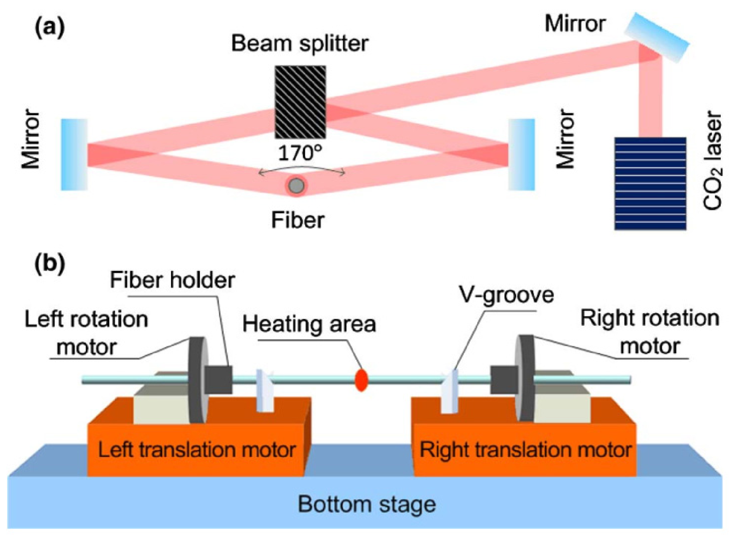
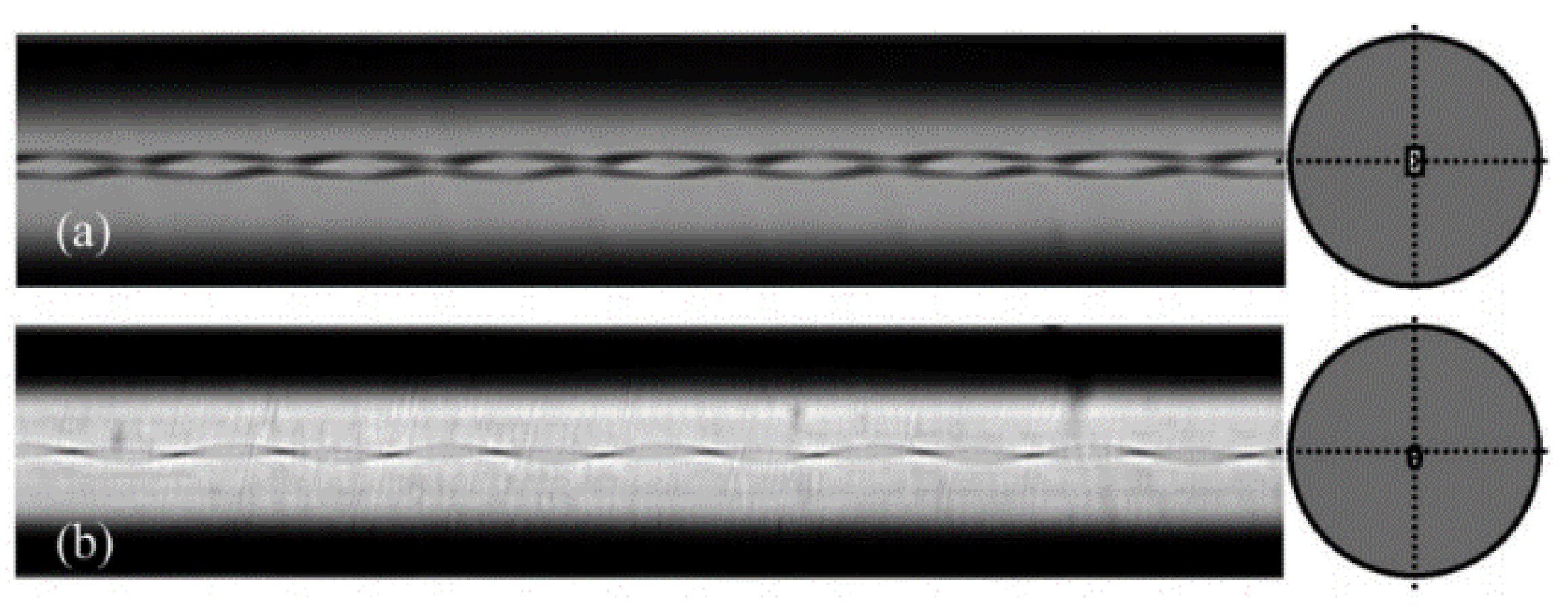
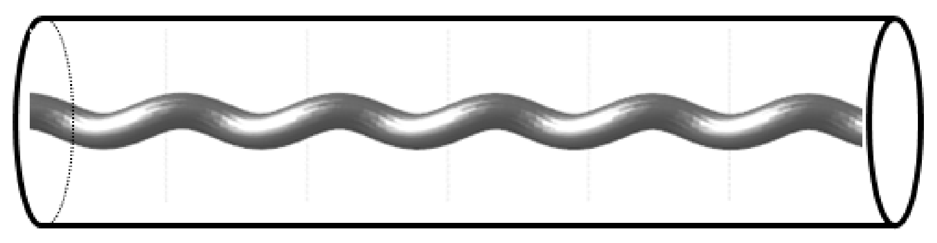
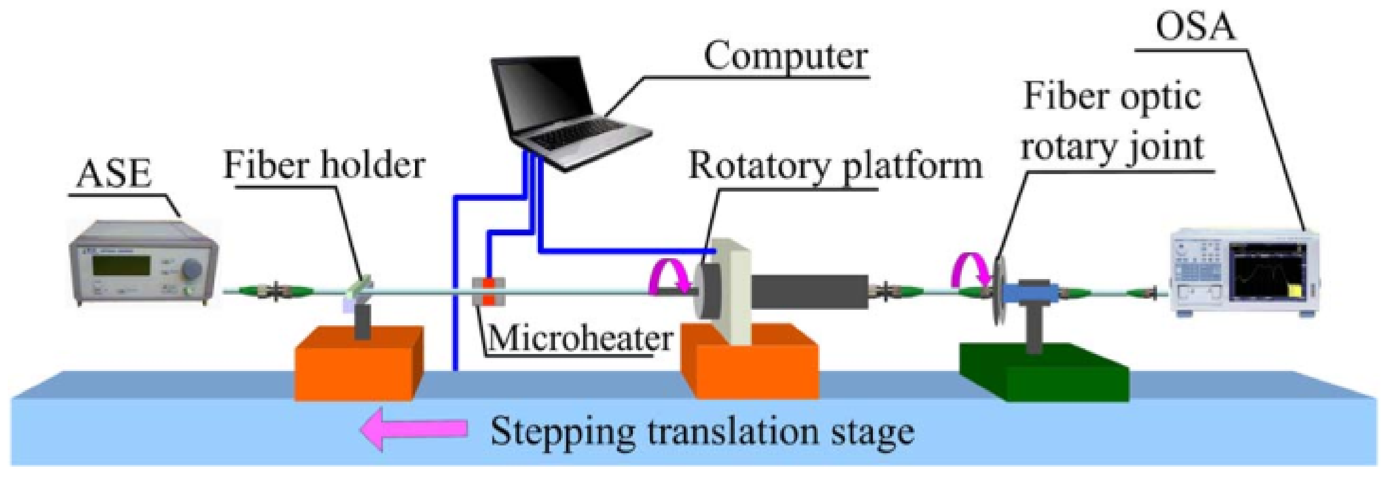
3. Fabrication Techniques for the HLPGs

In accordance with the advances on mode-couplings and mode-propagation theory in HLPGs, the fabrication techniques have also been developed especially in the recent 10 years. To date, various methods to fabricate the HLPGs have been proposed and demonstrated, among which, except for the most original one that was proposed and demonstrated by Poole et al. in [3] as shown in Figure 5, where the HLPG was realized by periodically winding a metal wire around a two-mode fiber and the mechanism to form the helical-type index-modulation in the HLPG was ascribed by the applied helical-type mechanical force, all the other established techniques could be classified as the thermal heating approaches, including the miniature oven (or the furnace, microheater) heating one [5,6,7,8,9,10,11,12], CO2 laser combined with the Sapphire tube method [13,14], hydrogen–oxygen burner heating approach [15,16], the focused CO2 laser beam heating method [17,18,19,20], and the arc discharge heating method [21,22]. The mechanisms enabling to form the helical-type index-modulation in HLPGs by using the above methods could be ascribed by either the residual torsional-stress relaxation, the helical deformation created in the surface of the fiber cladding, or the helical deformation in the boundary of the fiber core, etc.
In 2004, Oh [17] et al. firstly demonstrated a new method to fabricate the HLPG in a conventional single-mode fiber, the fabrication setup is shown in Figure 6, where the mechanism to form the HLPG was based on the newly-created helical-type deformation on the surface of the SMF fiber fabricated by using the focused CO2 laser. The fiber is fixed at centers of both the holder and synchronously rotated with the two motors at a constant speed. Meanwhile, the rotated fiber is continuously moved along the arrow direction (which means that the fiber is continuously passed through the focusing point of the CO2 laser region) together with the translating stage. Therefore, the period of the HLPG can easily be controlled by adjusting the speeds of both the fiber-moving stage and the rotator.
By using the setup as shown in Figure 7 [19], Zhang et al. successfully fabricated various kinds of HLPGs, which included the ones written in two-mode fiber [50], the double-cladding fiber [51], and the polarization-maintaining fiber-based ones [52], respectively. The difference between the two setups shown in Figure 6 and Figure 7 lies in that, for the case of Figure 7, during the laser heating, the left side of the fiber is fixed at clamp, and thus the obtained HLPG is really a twisted one which enables to provide higher torsional sensitivity [19] than that of the HLPG fabricated by using the setup shown in Figure 6. However, since the upper-side of the fiber is only heated by the focused laser, the obtained HLPGs are of the strong polarization-dependence, which are not available to some practical applications especially in fiber communication.
Both of the methods proposed above are simple and available to HLPGs written in various fibers even for the multicore fiber [53]. However, since the fiber surface is directly heated by the focused CO2 laser beam, the deformations and sometimes the structure defects produced within the fiber core are inevitable, which makes the HLPG too weak to stand for the external burdens such as the applied pressures, strains, and torsions etc. More importantly, performances of the fabricated HLPGs are strongly affected by the power fluctuation of the focused laser beam, and as a result the high repeatability and high yielding rate for the fabricated HLPGs could not be guaranteed.
In 2017, Kong et al. [54,55] proposed and demonstrated a double-sides heating method for fabrication of the HLPG. The fabrication setup is shown in Figure 8, where the contrary sides (i.e., the left and right sides in their case) of the fiber were simultaneously heated by two focused CO2 laser beams, which ensured that the fiber transverse section was uniformly heated, and as a result, one could be expected to obtain high-quality HLPGs. Meanwhile, the repeatability and the yielding rate of the HLPGs in fabrication could be considerably improved. Notably, their setup was based on the direct utilization of a commercial fusion splicer (Fujikura: LZM-100).
In accordance with the advances on the CO2 laser-based fabrication techniques, the techniques based on utilizations of the miniature oven (the furnace), the arc discharging, and hydrogen-oxygen burner heating approaches have also attracted a great interest and acquired many progresses especially in recent years. In 2004, Kopp et al. reported and demonstrated the pioneering works on chiral fiber gratings, i.e., the practically demonstration of the single- and double-helix HLPGs, which are shown in Figure 9a,b, respectively, where such two kinds of HLPGs were fabricated by periodically twisting the soften (fused) fibers in a high-temperature miniature oven [5,6,7,8]. In 2005, Ivanov et al. also demonstrated a single-helix HLPG as shown in Figure 10 [18], which was obtained by twisting a conventional single-mode fiber in a high-temperature oven.
In 2016, Ren et al. [12] reported and demonstrated an online method for fabrication of HLPG. The fabrication setup is shown in Figure 11, where the single-helix HLPG was fabricated by directly twisting a standard single-mode fiber in a microheater. However, the maximum length of the fabricated HLPG was limited due to the small heating region of the microheater, which made this method not available to fabrications of longer and more complex HLPGs, such as the phase-shifted and linearly chirped HLPGs.
In 2017, Russell et al. [11] proposed another fabrication scheme of HLPG as is shown in Figure 12, where the HLPG was fabricated by spinning the fiber preform during the drawing process of the fiber in a pulling tower, i.e., the conventional fiber fabrication technique.
However, all the miniature oven (furnace)-based methods mentioned above are lack of the flexibilities in fabrication. More importantly, with such methods, it is extremely difficult to precisely control the grating’s pitch, especially for some of the complex HLPGs where their local pitches would not be a constant. Instead, many of the research attentions were concentrated on the fabrication of HLPGs by using either the arc discharging heating, or the hydrogen-oxygen burner heating, or the CO2 laser heating approaches. For example, in 2017, Sun et al. [21] demonstrated an automatic arc-discharge technology for inscribing high-quality HLPG in a single-mode fiber, which was realized by directly employing a commercial fusion splicer (Fujikura: FSM-100P). By using the same arc discharge method, Li et al. [22] also demonstrated an ultra-short but strong HLPG (with a few period and 30 dB rejection depth), which was written in an all-solid photonic bandgap fiber (AS-PBGF) as shown in Figure 13, where the Figure 13a shows schematic of the helically twisted AS-PBGF, the Figure 13b shows the practical experimental setup, and the Figure 13c shows the side-view of the twisted and untwist AS-PBGFs.
In the same year of 2018, Fu et al. [15] successfully demonstrated a new method, i.e., making use of the hydrogen-oxygen flame for fabrication of the HLPGs, the setup is shown in Figure 14, where the fabrication procedures were divided into two steps. First, the utilized SMF was heated into the fused status with the hydrogen-oxygen flame, meanwhile the rotation motor rotated synchronously with the translation stages. The grating pitch was controlled by the ratio of the two moving speeds, i.e., ratio of the rotation motor and the translation stage speeds. Second, as soon as the heated fiber was moved away from the hydrogen-oxygen flame region, the fused fiber was cooled by the air and solidified immediately, and the elastic-optically induced helical-type index-change was produced in the fiber. From the results shown in Figure 14c, it is seen that, unlike the HLPGs fabricated by using the either the focused CO2 laser or the arc discharge heating methods, where there exist many deformations or defects in the fiber surfaces, an ideal HLPG with a clear and smooth surface has been obtained, showing the proposed method enabling to fabricate HLPGs with both the high quality and the superior performances. Later, they exploited the same method above to HLPGs but written in other kinds of fibers, such as the few-mode fiber [56] and the photonic crystal fiber [16] etc.
In view of the above, one can realize that for the fabrication methods using either the miniature oven or the microheater, the critical disadvantage lies in that it is difficult to precisely control the grating pitch especially for some of the complex HLPGs where their local pitches are not a constant. Meanwhile, for the methods using either the electric arc discharge or the focused CO2 laser heating methods, deformations and strong structure defects produced in the fiber are inevitable, which make the HLPG too weak to stand for the external burdens, such as the pressures, strains, and torsions etc. For the method using the hydrogen-oxygen flame, as of now, the HLPGs with a constant pitch have only been demonstrated. Some of the complex HLPGs such as linearly-chirped HLPGs, the phase-shifted HLPGs, and the multichannel HLPGs etc. have not been realized by using all the above techniques.
To address the above issues, in 2014, the authors’ research group proposed and demonstrated a new technique for fabrication of the HLPGs [13,14], the schematic diagram for the fabrication system is shown in Figure 15, where a sapphire tube was particularly utilized in place of the focal lens. Although the sapphire tube technique had been reported and successfully demonstrated for the fabrication of the micro/nano fiber [57], this was the first time that the HLPGs had been fabricated by using this technique. Here, it must be pointed that unlike the previous methods reported in Refs. [17,18,19,20] where a ZnSe lens was generally utilized in order to focus the CO2 laser beam directly onto the fiber, here a sapphire tube (which was used as a miniature oven with a constant temperature inside) was specially utilized in place of the focused lens [14]. Since the sapphire tube rather than the fiber was directly heated by the CO2 laser, the passed fiber within the tube region was homogeneously heated. As a result, HLPGs could easily and repeatedly obtained with a high yielding-rate and the thinned HLPGs with a diameter of ~80 μm were realized. The setup consists of a CO2 laser, three translation stages, a fiber rotation motor, and a testing system for measuring the transmission spectrum of the fabricated HLPG. To fabricate HLPG, firstly, the selected fiber (fixed at the clamp and the center of rotator) was homogenously heated to its fused status through a sapphire tube, meanwhile the heated fiber was homogenously twisted through the rotation motor. As shown in Figure 15, the sapphire tube was fixed at a spatial site, but the fiber was not fixed, which continuously moved through the tube by driving the motored stage 3. Period of the HLPG was precisely controlled by adjusting the speeds of both the fiber-moving stage and the rotator. Moreover, translation stages 1 and 2 provided a little longitudinal stress to the fiber in order so as to maintain the straightness of the fiber during the entire fabrication process.
By using such sapphire-tube-based CO2 laser heating technique, the authors’ research group developed various kind of HLPGs and demonstrated their applications to many aspects. In 2014 [13], the authors’ research group proposed and demonstrated a power-interrogated method enabling the simultaneous measurement of the temperature and torsion, which was based on utilization of a paired HLPGs with opposite helicities. By using two cascaded HLPGs and the phase-shifted HLPGs, respectively, the authors’ research group proposed and successfully demonstrated a flat-top band-rejection filters [58,59,60,61]. In 2017, the authors’ research group proposed and demonstrated an equivalent method to fabricate the phase-shifted HLPGs [62,63,64]. In 2018, by using two consecutively HLPGs but with opposite helicities, the authors’ research group successfully demonstrated an all-fiber circular polarization filter [65]. Furthermore, based on the phase-only and DC-sampled HLPGs, respectively, the authors’ research group successfully demonstrated a 9-channel HLPG and a 3-channel OAM mode converter, respectively [66,67]. Noted that all the HLPGs mentioned above were written in conventional single-mode fibers but with variable local pitches, and their lengths could be the ones ranging from 1.0 to 6.0 cm. Most recently, by using the HLPGs but written in four-mode fibers with a length about 5 cm, for the first time, the authors’ research group has successfully demonstrated the second-order [46], simultaneous first- and second-order [68], and simultaneous second- and third-order OAM mode generations [47], respectively.

4. Applications of the HLPGs

4.1. Applications of the HLPGs to Torsion Sensors

To date, as one kind of the fiber sensors, HLPGs have been used for measurement of the environment and the physical parameters, e.g., temperature, stress, torsion, bending curvature, refractive index, and liquid level, etc. The details and more comprehensive introductions about the widespread applications of the HLPGs could be found in Refs. [69,70]. In this subsection, we concentrate on the applications of the HLPGs to the torsion sensors. Compared with the other fiber-based ones, the HLPG-based torsion sensors have 5–10 times higher torsion responsivity, and meanwhile the torsion direction could be discerned by using only one HLPG itself, which makes the HLPGs especially suitable to the fiber-based torsion sensors.
In 2004, when Oh et al. first demonstrated their HLPG fabricated by using the focused CO2 laser technique [17], they also investigated the spectral performances of the fabricated HLPG under different external torsions, the results are shown in Figure 16. From the results shown in this figure, they revealed for the first time that the resonant wavelengths shifted linearly with the applied external torsion. The co-directional or contra-direction torsion to the helix of the HLPG would cause the resonant peaks shifted to short or long wavelength direction, respectively, which were ascribed by the decrease and increase of the helical pitch when the external torsions were applied. The results reported in [17] had been fully confirmed by the authors’ research group in 2014 [13], where the tested objects were the HLPGs fabricated by using the sapphire tube-based CO2 laser beam technique. Since then, the HLPG-based torsion sensors have attracted increasingly interest. In 2016, by comparing the torsional characteristics in both the single-helix HLPG and the conventional LPG, Zhang et al. [19] demonstrated that HLPGs had much higher torsion and bending sensitivities than those of the LPG, and such high torsional sensitivity of the HLPGs could be attributed to the screw-type structure induced by the scanning laser in the twisted fiber [19]. In 2017, Sun et al. [21] and Kong et al. [54] also investigated the torsional performances of the HLPGs, where the utilized HLPGs were fabricated by using the arc electric discharge and the dual-sides focused CO2 laser heating approaches, respectively. Much higher torsional responsivities than those of the conventional LPGs have been obtained in both cases, which fully validates the availabilities and the benefits of making use of the HLPG as all-fiber type torsion sensor.
Besides the HLPGs written in conventional single-mode fibers, the torsion performances of the HLPGs written in other kinds of fibers have also been investigated. In 2016, Zhang et al. [50] firstly demonstrated the torsion characteristics of the HLPG but written in a two-mode fiber (TMF). The results are shown in Figure 17, where Figure 17a shows the measurement results while the co-direction or contra-direction torsion were applied to the conventional LPG and the SMF-based HLPG, whereas Figure 17b shows the measurement results for a HLPG written in TMF. It was found that, for the TMF, the torsion sensitivity was about 0.47 nm/rad/m, which was one order magnitude higher than that of the conventional LPG. Moreover, it was found that the resonant wavelength shifted linearly towards the longer wavelength when the co-directional torsion was applied and vice versa. Such phenomena are completely opposite to those occurring in SMF-based HLPG (as shown in Figure 17a), the reason to cause this difference could be ascribed by the fact that due to the mode dispersion, the difference in group indices between the core mode LP01 and the coupled core mode/cladding mode LP11 (TMF/SMF) is of the wavelength dependence, whose magnitude is equivalent to d Λ / d λ . At a wavelength near 1.55 μm, the magnitude of d Λ / d λ is negative one for TMF fiber [3] and positive one for SMF, which means that, for FMF-based HLPG, when the co-directional torsion is applied, the pitch Λ will be decreased and as a result of the negative value of d Λ / d λ , the resonant wavelength λ will become large, i.e., a shift to longer wavelength direction. The same phenomenon could be found in other HLPGs fabricated in four-mode fibers and the PCFs as well [22].
In 2017, Cao et al. [20] accomplished the further investigation on sensing characteristics of the TMF-based HLPGs. They experimentally demonstrated that in addition to the high torsion sensitivity (up to 0.7768 nm/rad/m), the HLPGs were also of the less temperature-dependence because the coupled modes were the intra-core ones, showing the potential application of this kind of HLPGs to temperature-insensitive torsion measurement. In 2019, they further invested the torsional performances of the HLPGs but written in double-cladding [51] and polarization-maintaining fibers [52], respectively. A high torsion sensitivity up to −0.40 nm/rad/m was obtained for the former HLPG while the intensity sensitivities of torsion up to 5.98 dB/(rad/m) for co-direction and –5.97 dB/(rad/m) for counter-direction torsions applied were obtained for the later HLPG.
On the other hand, the torsion characteristics for those HLPGs written in other kinds of fibers, such as the PCF, all-solid photonic bandgap fiber (AS-PBGF), and multicore fiber, have also been demonstrated.
In 2013, Xi et al. demonstrated a HLPG written in a solid-core PCF [71], where they investigated the torsion and strain (axial tension) characteristics and revealed that the torsion-induced shift in resonant wavelength was determined only by the twist rate whereas the tension-induced wavelength shift was determined by both the photoelastic effect and the change in twist rate (torsion). A sensitivity of ~49 nm/rad/mm in torsion was obtained there. In 2017, Shen et al. demonstrated another HLPG but inscribed in a multicore fiber (MCF). They investigated the torsional characteristics and showed that the obtained HLPG had a torsion sensitivity of 0.198 nm/rad/m and presents less cross-sensitivity to temperature [53].
In 2018, Li et al. [22] proposed and demonstrated another kind of HLPG fabricated in an all-solid photonic bandgap fiber. Torsional characteristics of such HLPGs were also investigated, the results are shown in Figure 18. Here, it can be seen that the mechanical-torsion sensitivities of 112.1 and 115.5 nm/rad/mm for the HLPGs with twist rates of 0.909 and 1.818 rad/mm were obtained, showing that such kinds of HLPGs could potentially be used as the torsion sensors.
However, all the torsion sensors mentioned above rely on the cost-inefficient wavelength-interrogation method, i.e., in order to precisely measure a wavelength shift, either an optical spectrum analyzer (OSA) with a high wavelength-resolution or an extremely narrow line-width tunable laser with both a wide tuning region and a high wavelength-scanning speed are desired. All these devices mentioned above are extremely expensive, bulky, and thus not available for most of the in-sites applications. On the other hand, it is known that, for HLPGs based sensor systems, the resonance wavelength is generally sensitive to both temperature and torsion, thus, there has always existed a need to develop a simple and new technique enabling to discriminate these two effects simultaneously. The simultaneous measurement of temperature and torsion is an important topic and strongly desired for practical application of the HLPG-based sensors. To address the above two issues, in 2014, the authors’ research group proposed and experimentally demonstrated a power-interrogated sensor system enabling the simultaneous measurements of the torsion and temperature, which was based on utilization of paired HLPGs with opposite helicities as shown in Figure 19a [13]. Unlike most of the previous fiber grating-based sensing system, the paired HLPGs were simultaneously used as both the sensing and the interrogating elements and thus the bulk and high-cost wavelength-interrogating device were eliminated, the experimental results are show in Figure 19b–e, in which not only the torsion but also the torsion direction were determined simultaneously. The temperature sensitivity obtained was is estimated to be ~41 pm/°C within a range of 20–150 °C, and the torsion responsivities obtained are ~−1.414 nm/rad/m and ~1.276 nm/rad/m, respectively within a rotation angle of −360°~360° [13]. Furthermore, in 2018, based on the same two-cascaded HLPGs but working at three different cladding modes, the authors’ research group proposed and demonstrated a novel method enabling for the simultaneous measurements of the torsion, strain and temperature while the crosstalk effects of these three parameters could be eliminated [72].

4.2. Applications to All-Fiber Circular Polarization Filter, All-Fiber Band-Rejection Filter, and All-Fiber Circular-Birefringent/Circular-Dichromatic Components

4.2.1. All-Fiber Circular Polarization Filter

In 2004, Kopp et al. firstly introduced the chiral long-period fiber gratings (i.e., the HLPG) [6], where they proposed and demonstrated that HLPGs were of the inherent polarization-selection, which enabled to control the states of the circular polarization light. They experimentally demonstrated that, the HLPGs with double-helix structures were polarization dependent and interact only with the elliptically polarized wave with the same handedness as the structure, whereas the ones with single-helix structures were polarization independent [5,6]. In 2006, they further proposed and demonstrated an in-fiber linear polarizer [73], which was realized by using a special HLPG adiabatically written in a birefringent optical fiber with various pitches.
In 2009, Shvets et al. [27] proposed and further proved that the mechanisms to cause the polarization dependences in double-helix HLPG and polarization independence in single-helix HLPG arose from the fact that in any HLPGs, the angular momentum conservation condition must be satisfied, which however, was not required for the conventional LPGs. In 2011, Yang et al. [74] proposed an adiabatic circular polarizer, where the HLPG written in a high-birefringence fiber was assumed and the mode selections for circular polarization (CP) light reported in [30] were utilized. Their results, however, have not be validated by the experimental ones provided by Jiang et al. [52], where the HLPG written in a polarization maintaining fiber was firstly reported and experimentally demonstrated.
In 2018, the authors’ research group proposed and experimentally demonstrated a novel HLPG-based circular polarization filter, which was realized based on utilization of two consecutively-cascaded single-helix HLPGs but with opposite helicities [65]. The mode conversions, polarization dependences, and the spectral characteristics of such HLPG-based components were analyzed both theoretically and experimentally [76].
In addition to the above works, most recently, the works related to polarization control by using either the helically-twisted PCF or the twisted helical-core fiber have also attracted increasing interest. In 2016, by using the full-vector method, Napiorkowski et al. [36] analyzed the effect of resonant coupling between the core and the cladding in a helical core fiber but with large core offset. Based on the simulation results, they came to the conclusion that such components could be used as broadband circular polarizers.
In 2018, by using full-vector finite-element beam propagation method (FFE-BPM), Fujisawa et al. [42] investigated and analyzed, for the first time, the polarization and transmission characteristics of helically twisted PCFs with off-axis cores, where they anticipated that such components could be used for core-position-dependent polarization control devices.
In 2020, Usuga-Restrepo et al. [77] proposed and numerically demonstrated a novel all-fiber polarization beam splitter, which was based on a helically twisted two-core PCF fiber coupler. The proposed device has the ability to spatially split the circularly polarized optical modes with opposite handedness at the fiber core.

4.2.2. All-Fiber Flat-Top Band-Rejection Filter

As is well known that LPG can generally be used as an optical band-rejection filter with a bandwidth of several tens of nanometers. However, it is extremely difficult to precisely control the profile of the resulted notch, especially for an LPG with a broad flat-top rejection-band, there has rarely been practically realized due to some unrealistic demands in the grating’s fabrication, although it is one of the key components and strongly desirable in fiber communication system as well as fiber sensing system. Early in 2007, Shin et al. [78] proposed and demonstrated a bandwidth-tunable band-rejection filter, which consisted of a pair of HLPGs but with opposite helicities as shown in Figure 20, where a band-rejection filter with turning range ~14 nm at rejection depth of 15 dB was successfully obtained. However, a large separation (>10 cm) between the two HLPGs were adopted, which made the spectral interference of the two individual HLPGs inevitable. As a result, there existed a large fluctuation in loss-depth (>10 dB) and a flat-top band-rejection filter was not realized. To address the above issue, in 2016, the authors’ research group proposed and demonstrated an improved method, which was realized by consecutively cascading two single-helix HLPGs (SHLPGs) with opposite helicities and a flat-top filter with a bandwidth of ~13 nm@0.5 dB and ~15 nm@1 dB was successfully obtained [58]. However, the flat-top rejection band was achieved at the cost of sacrificing the rejection depth of the HLPG and the rejection depth obtained was limited to a magnitude less than 12 dB. To increase this rejection depth, in 2017, the authors’ research group further proposed and demonstrated an improved approach [59], where the incident light underwent double passes of the consecutively-cascaded HLPGs and, as a result, a flat-top filter with a rejection depth larger than 34 dB was obtained.
However, the HLPG-based filters reported above have one critical issue, i.e., their spectra were strongly dependent on the polarization status of the incident light, which inevitably restrained them from the practical applications. In 2018, the authors’ research group proposed and experimentally demonstrated a simple and efficient method enabling to produce a polarization-insensitive flat-top band-rejection filter, the schematic diagram is shown in Figure 21, where a cladding mode stripper (an oil region was utilized in this study) was employed and inserted at the central region of the two cascaded SHLPGs [60]. Due to the higher refractive-index of the oil, the cladding modes produced in the first grating would escape from the cladding layer within the oil region and thus could not be coupled back to the second cSHLPG. As a typical example, a flat-top filter with a rejection depth of ~17 dB, a bandwidth of ~14 nm@1 dB, and the maximum polarization-dependent loss (PDL) of ~1.5 dB, was successfully demonstrated.
Last but not the least, in 2020 the authors’ research group have proposed and demonstrated another new method enabling to produce a flat-top band-rejection filter, which was achieved by using a phase-modulated HLPG [61]. Unlike most of the LPG-based and the HLPG-based band-rejection filters reported so far, the proposed band-rejection filter was inherently polarization-independent. Moreover, only one HLPG was required, which considerably facilitated the fabrication processes and made the designed HLPG particularly suitable for fabrication with using the CO2 laser-writing platform. As a typical example, a polarization-independent band-rejection filter with a bandwidth of ~10 nm@-20 dB and a rejection depth of ~28 dB was successfully achieved.

4.2.3. Optical Activity in HLPG and Its Potential Applications

Early in 1979, Ulrich et al. [1] had firstly proposed and demonstrated that the twisted fibers could be used as polarization rotators, where they indicated that when the fiber was strongly twisted, due to the shear strain originated from either the applied torsion or the shape deformation in the fiber core, the photo-elastically optical activity, i.e., the induced circular birefringence would appear in such fiber, which was proportional to the twist rate and the photoelastic coefficient of the fiber. In 1988, Bassett [79] further revealed that the circular birefringence could be produced in the fiber only in the presence of material anisotropy, and such material anisotropy could be originated by the stress implanted in the fiber core. In 2013, the optical activity in twisted solid-core PCFs had been firstly investigated by Xi et al. [80], where they demonstrated both theoretically and experimentally that such fibers exhibited circular birefringence despite there being no linear birefringence or anisotropy in the structure (i.e., the considered PCF has zero linear birefringence and an on-axis core), manifesting the completely different mechanism for generation of the optical activity with those assumed to be resulted from the photoelastical effects in [1,79]. The mechanism to produce such optical activity was considered to be the direct result of spin-orbital interaction [81]. Subsequently in 2005, Wong et al. [82] revealed that the core-guided mode in helically twisted PCF exhibited resonantly enhanced optical activity and circular dichroism near the peak wavelength of the transmission dip and anticipated that such kind of HLPGs could find potential applications in chiral-optics, polarization control, filtering, microscopy, and spectroscopy etc.
In 2018, by utilizing the advanced beam propagation method to a helicoidal system, Nakano et al. [83] theoretically investigated the transmission characteristics of the helically twisted PCF, where the optical-activity discontinuity and the circular dichroism previously proposed and demonstrated by Wong et al. in [82] were perfectly reproduced, which numerically testified that there really existed optical activity as well as the circular dichroism in helical twisted PCFs. Recently, through both the experimental and the numerical investigations on a twisted single-ring hollow-core PCF, Roth et al. (the same group authors in [82,83]) have further revealed that there exist strong circular dichroism for the HE11 mode in such PCF fiber, both the numerical and the experimental results were shown in Figure 22 [84], where it can be seen that, at a wavelength near 1.59 μm, there existed large deference up to 8.3 dB in loss between the right circular polarization (RCP) and the left circular polarization (LCP) lights.
Here, it must be noted that the optical activity can be found not only in the twisted PCFs, but also in the single-helix HLPGs. Most recently, by analyzing the circular dichroism as well as the polarization dependence loss (PDL) spectrum of such HLPGs [49], the authors’ research group has demonstrated both numerically and experimentally that the HLPGs exhibit the enhanced circular dichroism (CD) near the resonant wavelengths of the HE and TE/TM modes, respectively, the results can be found in Figure 4, from which it can be seen that there exists a difference (about 0.24 nm) in resonant wavelength between the pure LCP light and the pure RCP light, which implicitly means that the LCP light and the RCP light undergo different effective indices and different transmission losses. Although both of the above parameters obtained are extremely small and in general can be neglected when full bandwidth of the resulted notch (tens of nanometers) is considered. Nevertheless, the results shown in Figure 4 verify the existence of the optical activity and circular dichroism in HLPG, and implicitly indicate that, like the twisted PCF, HLPGs may also find potential applications to the fields of the biochemistry and the chiral-optics.

4.3. Applications of the HLPGs to All-Fiber OAM Mode Converters

In the past decades, OAM beams (also known as optical vortices) have been extensively studied and have been found versatile applications in the fields, such as optical manipulation, optical trapping, nanoscale microscopy, quantum information processing, and optical fiber communication etc. [85,86,87,88,89,90]. To date, various methods enabling to generate the OAM beams have been developed. Of which, attributed to the unique properties, such as the compact size, extremely low loss, cost-effectiveness, high conversion efficiency, high anti-perturbation, inherent compatibility with the fiber etc., the HLPGs-based OAM mode generators (including both the conventional fibers and the PCFs ones) have recently attracted special interests [3,9,15,16,24,26,39,46,47,66,67,68,91,92,93,94,95,96].
The original idea using the conventional-fiber based HLPG as an OAM mode converter was proposed by Alexeyev et al. [24], where the mechanism to create the OAM modes in HLPGs was ascribed by the effect of spin-orbit interaction reported in [25]. Almost at the same time, Yan et al. [26] theoretically demonstrated that HLPGs could be used as OAM mode converters turning the fundamental mode to higher-order azimuthal modes, i.e., the OAM modes. In 2015, Fang et al. [92] conducted a theoretical study of HLPGs written in ring-core fibers, showing that such devices could have strong flexibilities for generation, conversion, and exchange of the fiber-guided OAM modes. In 2018, Fu et al. experimentally demonstrated a polarization-independent HLPG-based OAM mode converter [15], which was the first report to practically realize the first-order OAM (OAM-1) mode converter by using one HLPG written in a SMF. In 2019, they further proposed and demonstrated a polarization independent OAM-1 mode converter [56], which was realized by using a HLPG written in a two-mode fiber (TMF). Almost at the same time, by using a second-order helical fiber grating written in a few-mode fiber [46], the authors’ research group successfully demonstrated an all-fiber second-order OAM mode generation with a conversion efficiency of ~90%. In 2020, the authors’ research group proposed and experimentally demonstrated a new method enabling the simultaneous generation of the first- and the second-order OAM modes [68], which was realized by two consecutively cascaded HLPGs but working in the first- and second-diffraction orders, respectively. In 2021, the authors’ research group have proposed and experimentally demonstrated a novel method enabling the simultaneous generation of the second- and the third-order OAM modes with a conversion efficiency larger than 95% at different wavelengths [47], this is the first time, that the OAM-2 and the OAM-3 modes have been simultaneously achieved by using only one fiber component, i.e., the HLPG but working at its higher diffraction orders, the measured transmission spectrum was shown in Figure 23, where the insets showed the intensity and phase distributions of the OAM-3 mode observed at wavelength of 1555.0 nm, and those of the OAM-2 mode observed at wavelength of 1578.0 nm, respectively.
To further expand the bandwidth of HLPF-based OAM mode converters to covering the whole C or L band of the optical fiber communication, multichannel HLPGs and broad-band HLPGs have also been explored and developed. The authors’ research group numerically analyzed the mode dispersion effects on the spectra of the HLPG and the HLPG-based broad-band components [95] which generally was ignored especially when the considered wavelength region is narrow enough, and proposed and demonstrated a simple quantification method enabling to correctly evaluate the modal dispersion effect on HLPG-based components. Based on the above results, the authors’ research group further proposed and demonstrated 3-channel (3 wavelengths) and 5-channel OAM mode converters [66,67], which were realized by using multichannel HLPGs fabricated with the DC-sampling and superimposing approaches, respectively. The transmission spectrum for one typical 3-channel HLPG is shown in Figure 24, where the insets show the intensity and phase distributions of the OAM-1 mode observed at three different wavelengths, respectively.
In 2000, Ren et al. [96] proposed and numerically demonstrated an ultra-broad band OAM mode converter, which was realized by using a special designed HLPG working at wavelength near the dispersion turning point of a high-order radial cladding mode. However, the OAM modes there were produced in the cladding region, since the considered fiber was a SMF one. Zhao et al. [93] further improved the above method by replacing the SMF with the a two-mode fiber, they experimentally demonstrated an all-fiber ultra-broadband mode converters with a tunable bandwidth, the obtained results were shown in Figure 25, where it could be seen that the first order OAM mode converter with a bandwidth ~297 nm, tunable range of ~91 nm, and conversion efficient larger than 90% were successfully obtained, which presented the best results of the HLPG-based OAM mode converter reported to date.
On the other hand, the PCF-HLPG based OAM generators have also been developed in the past decade. In 2012, Wong et al. investigated the transmission spectrum of a helically twisted PCF and theoretically revealed, for the first time, that in cladding region of such PCF, the fifth-, sixth-, seventh-, and the eighth-order OAM modes were successfully excited [9]. In 2018, they further proposed and demonstrated that in a twisted coreless PCF, not limited to the one guided circularly polarized helical Bloch mode (HBM) which carried OAM, a family of the guided HBMs could be supported, anticipating that such a kind of PCFs would also be used to generate rich OAM modes and find potential applications in optomechanics, microscopy, etc. [40]. In 2018 and sooner later, by using the PCF-based HLPG, Fu et al. [16,75] successfully demonstrated the generation of the fifth- and the sixth- order OAM modes, which was the first report for the practical demonstration of such higher-order OAM modes in HLPG-based devices.

5. Conclusions and Prospects

In this paper, we have briefly reviewed the developing history and the recent advances on HLPGs in three aspects, i.e., the mode-coupling theories, the fabrication techniques, and the applications. It is shown that attributed to the intrinsic helicity characteristics which are especially suitable to control the loss, polarization and orbit-angular-momentum (OAM) states of the light in optical fiber, the, HLPGs have recently attracted a great research interest and have found various applications, such as the mode-converters, the torsion sensors, the band-rejection filters, wave plates, linear- and circular-light polarizers, and OAM mode generators, etc. It is believed that HLPGs and the HLPGs-based devices would find further applications to not only the fields of optical sensor and optical communication, but also other fields such as the ultrahigh precision measurement, quantum optics, and biochemistry etc. For examples, as unique all-fiber devices carrying both the SAM and the OAM, HLPGs can be used as compact and liquid-proof either the optical manipulator or the optical tweezers, providing the unprecedented flexibilities and compactness than those of the present bulk-based ones. Moreover, the HLPGs-based chiral-optical device, i.e., the spin angular momentum-dependent and OAM-dependent HLPGs, would be another application in the near future, where the left-handed or right-handed miniatures, such as the DNA/RNA-like molecules, chemical molecules, and living cells, etc., can be discerned, sorted, and separated as well.
On the other hand, the studies to further clarify the mode-coupling rules in HLPGs especially for the higher OAM modes, and to further explore new fabrication techniques enabling to fabricate helical fiber Bragg grating (HFBG) and any kind of the customer-designed HLPGs still remain the challenges to us.
First, the mechanism that the HLPGs can support the OAM modes has not been clearly clarified yet in theory, although some authors ascribed this phenomenon (i.e., existences of the stable OAM modes in HLPGs) to the interaction of the spin angular momentum (SAM) with the OAM, but all lack experimental verification. Moreover, it is still not clear whether, within the HLPGs, the SAM and the OAM can be exchanged each other or, subjected to which conditions, these two kind momentums can be changed each other.
Second, it remains a challenge for one to precisely control the profile (envelope) of the resulted spectrum during the HLPG’s fabrication. This is especially so for a HLPG with a broad flat-top rejection-band, although it is one of the key components and strongly desirable in the fields of fiber communication as well as fiber sensors. This has rarely been practically realized due to the unrealistic demands to the apodization (i.e., the index-modulation distribution) during the HLPG’s fabrication.
Third, although methods of making use of the HFBGs for generation and conversion of higher order OAM modes have been proposed and theoretically demonstrated for some years [97,98], due to the fabrication difficulties, HFBGs have rarely been experimentally demonstrated until present. It is expected that much stronger optical activity and circular dichroism could be observed in HFBGs than those in HLPGs.

Author Contributions

Writing and editing, H.Z. and H.L. All authors have read and agreed to the published version of the manuscript.

Funding

Nippon Sheet Glass Foundation for Materials Science and Engineering; KDDI Foundation for Research Grant Program; Yazaki Memorial Foundation for Science & Technology; Natural Science Foundation of Jiangsu Province (BK20201370).

Conflicts of Interest

The authors declare no conflict of interest.

References

  1. Urich, R.; and Simon, A. Polarization optics of twisted single-mode fibres. Appl. Opt. 1979, 18, 2241–2251. [Google Scholar] [CrossRef] [PubMed]
  2. Barlow, A.; Ramskov-Hansen, J.; Payne, D. Birefringence and polarization mode-dispersion in spun single-mode fibers. Appl. Opt. 1981, 20, 2962–2968. [Google Scholar] [CrossRef] [PubMed]
  3. Pool, C.D.; Townsend, C.D.; Nelson, K.T. Helical-grating two-mode fiber spatial-mode coupler. J. Lightwave Technol. 1991, 9, 598–604. [Google Scholar] [CrossRef]
  4. Lee, K. Coupling analysis of spiral fiber gratings. Opt. Commun. 2001, 198, 317–324. [Google Scholar] [CrossRef]
  5. Kopp, V.I.; Genack, A.Z. Double-helix chiral fibers. Opt. Lett. 2003, 28, 1876–1878. [Google Scholar] [CrossRef]
  6. Kopp, V.I.; Churikov, V.M.; Singer, J.; Chao, N.; Neugroschl, D.; Genack, A.Z. Chiral fiber gratings. Science 2004, 305, 74–75. [Google Scholar] [CrossRef]
  7. Churikov, V.M.; Kopp, V.I.; Genack, A.Z. Chiral diffraction gratings in twisted microstructured fibers. Opt. Lett. 2010, 35, 342–344. [Google Scholar] [CrossRef]
  8. Kopp, V.I.; Park, J.P.; Wlodawski, M.; Singer, J.; Neugroschl, D.; Genack, A.Z. Chiral Fibers: Microformed optical waveguides for polarization control, sensing, coupling, amplification, and switching. J. Lightwave Technol. 2014, 32, 605–613. [Google Scholar] [CrossRef]
  9. Wong, G.; Kang, M.; Lee, H.; Biancalana, F.; Conti, C.; Weiss, T.; Russell, P. Excitation of orbital angular momentum resonances in helically twisted photonic crystal fiber. Science 2012, 337, 446–449. [Google Scholar] [CrossRef]
  10. Beravat, R.; Wong, G.; Frosz, M.; Xi, X.; Russell, P. Twist-induced guidance in coreless photonic crystal fiber: A helical channel for light. Sci. Adv. 2016, 2, e1601421. [Google Scholar] [CrossRef] [Green Version]
  11. Russell, P.; Beravat, R.; Wong, G. Helically twisted photonic crystal fibres. Phil. Trans. R. Soc. A 2017, 375, 20150440. [Google Scholar] [CrossRef]
  12. Ren, K.; Ren, L.; Liang, J.; Kong, X.; Ju, H.; Xu, Y.; Wu, Z. Online fabrication scheme of helical long-period fiber grating for liquid-level sensing. Appl. Opt. 2016, 55, 9675–9679. [Google Scholar] [CrossRef]
  13. Xian, L.; Wang, P.; Li, H. Power-interrogated and simultaneous measurement of temperature and torsion using paired helical long period fiber gratings with opposite helicities. Opt. Express 2014, 22, 20260–20267. [Google Scholar] [CrossRef]
  14. Wang, P.; Li, H. Helical long-period grating formed in a thinned fiber and its application to a refractometric sensor. Appl. Opt. 2016, 55, 1430–1434. [Google Scholar] [CrossRef]
  15. Fu, C.; Liu, S.; Bai, Z.; He, J.; Liao, C.; Wang, Y.; Li, Z.; Zhang, Y.; Yang, K.; Yu, B.; et al. Orbital angular momentum mode converter based on helical long period fiber grating inscribed by hydrogen–oxygen flame. J. Lightwave Technol. 2018, 36, 1683–1688. [Google Scholar] [CrossRef]
  16. Fu, C.; Liu, S.; Wang, Y.; Bai, Z.; He, J.; Liao, C.; Zhang, Y.; Zhang, F.; Yu, B.; Gao, S.; et al. High-order orbital angular momentum mode generator based on twisted photonic crystal fiber. Opt. Lett. 2018, 43, 1786–1789. [Google Scholar] [CrossRef] [Green Version]
  17. Oh, S.; Lee, K.R.; Paek, U.C.; Chung, Y. Fabrication of helical long-period fiber gratings by use of a CO2 laser. Opt. Lett. 2004, 29, 1464–1466. [Google Scholar] [CrossRef]
  18. Ivanov, V. Fabrication of long-period fiber gratings by twisting a standard single-mode fiber. Opt. Lett. 2005, 30, 3290–3292. [Google Scholar] [CrossRef]
  19. Zhang, L.; Liu, Y.; Cao, X.; Wang, T. High sensitivity chiral long-period grating sensors written in the twisted fiber. IEEE Sens. J. 2016, 16, 4253–4257. [Google Scholar] [CrossRef]
  20. Cao, X.; Liu, Y.; Zhang, L.; Zhao, Y.; Wang, T. Characteristics of chiral long-period fiber gratings written in the twisted two-mode fiber by CO2 laser. Appl. Opt. 2017, 56, 5167–5171. [Google Scholar] [CrossRef]
  21. Sun, B.; Wei, W.; Liao, C.; Zhang, L.; Zhang, Z.; Chen, M.; Wang, Y. Automatic arc discharge-induced helical long period fiber gratings and its sensing applications. IEEE Photonics Technol. Lett. 2017, 29, 873–876. [Google Scholar] [CrossRef] [Green Version]
  22. Li, J.; Fan, P.; Sun, L.; Wu, C.; Guan, B. Few-period helically twisted all-solid photonic bandgap fibers. Opt. Lett. 2018, 43, 655–658. [Google Scholar] [CrossRef]
  23. Alexeyev, C.; Yavorsky, M. Generation and conversion of optical vortices in long-period helical core optical fibers. Phy. Rev. A 2008, 78, 043828. [Google Scholar] [CrossRef]
  24. Alexeyev, C.; Fadeyeva, T.; Lapin, B.; Yavorsky, M. Generation and conversion of optical vortices in long-period twisted elliptical fibers. Appl. Opt. 2012, 51, C193–C197. [Google Scholar] [CrossRef] [Green Version]
  25. Alexeyev, C.; Alexeyev, A.; Lapin, B.; Milione, G.; Yavorsky, M. Spin-orbit-interaction-induced generation of optical vortices in multihelicoidal fibers. Phy. Rev. A 2013, 88, 063814. [Google Scholar] [CrossRef]
  26. Xu, H.; Yang, L. Conversion of orbital angular momentum of light in chiral fiber gratings. Opt. Lett. 2013, 38, 1978–1980. [Google Scholar] [CrossRef]
  27. Shvets, G.; Trendafilov, S.; Kopp, V.I.; Neugroschl, D.; Genack, A.Z. Polarization properties of chiral fiber gratings. J. Opt. A, Pure Appl. Opt. 2009, 11, 074007. [Google Scholar] [CrossRef]
  28. Erdogan, T. Cladding-mode resonances in short- and long period fiber grating filters. J. Opt. Soc. Am. A 1997, 14, 1760–1773. [Google Scholar] [CrossRef]
  29. Qian, J.; Su, J.; Xue, L.; Yang, L. Coupled-mode analysis for chiral fiber long-period gratings using local mode approach. J. Quantum. Electron. 2012, 48, 49–55. [Google Scholar] [CrossRef]
  30. Xu, H.; Yang, L.; Han, Z.; Qian, J. Higher-order mode couplings in double-helix chiral long-period fiber gratings. Opt. Comm. 2013, 201, 207–214. [Google Scholar] [CrossRef]
  31. Ma, X.; Liu, C.; Chang, G.; Galvanauskas, A. Angular-momentum coupled optical waves in chirally-coupled-core fibers. Opt. Express 2011, 19, 26515–26528. [Google Scholar] [CrossRef] [PubMed]
  32. Napiorkowski, M.; Urbanczyk, W. Rigorous simulations of a helical core fiber by the use of transformation optics formalism. Opt. Express 2014, 22, 23108–23120. [Google Scholar] [CrossRef] [PubMed]
  33. Napiorkowski, M.; Urbanczyk, W. Rigorous simulations of coupling between core and cladding modes in a double-helix fiber. Opt. Lett. 2015, 40, 3324–3327. [Google Scholar] [CrossRef] [PubMed]
  34. Nicolet, A.; Zolla, F.; Guenneau, S. Modelling of twisted optical waveguides with edge elements. Eur. Phys. J. Appl. Phys. 2004, 28, 153–157. [Google Scholar] [CrossRef]
  35. Nicolet, A.; Zolla, F.; Agha, Y.; Guenneau, S. Geometrical transformations and equivalent materials in computational electromagnetism. COMPEL 2008, 27, 806–819. [Google Scholar] [CrossRef]
  36. Napiorkowski, M.; Urbanczyk, W. Coupling between core and cladding modes in a helical core fiber with large core offset. J. Opt. 2016, 18, 055601. [Google Scholar] [CrossRef]
  37. Napiorkowski, M.; Urbanczyk, W. Role of symmetry in mode coupling in twisted microstructured optical fibers. Opt. Lett. 2018, 43, 395–398. [Google Scholar] [CrossRef]
  38. Zolnacz, K.; Napiorkowski, M.; Kiczor, A.; Makara, M.; Mergo, P.; Urbanczyk, W. Bend-induced long period grating in a helical core fiber. Opt. Lett. 2020, 45, 1595–1598. [Google Scholar] [CrossRef]
  39. Xi, X.; Wong, G.; Frosz, M.; Babic, F.; Ahmed, G.; Jiang, X.; Euser, T.; Russell, P. Orbital-angular-momentum-preserving helical Bloch modes in twisted photonic crystal fiber. Optica 2014, 1, 165–169. [Google Scholar] [CrossRef]
  40. Roth, P.; Wong, G.; Frosz, M.; Ahmed, G.; Russell, P. Full-field characterization of helical Bloch modes guided in twisted coreless photonic crystal fiber. Opt. Lett. 2019, 44, 5049–5052. [Google Scholar] [CrossRef]
  41. Fujisawa, T.; Sato, T.; Saitoh, K. Full-vector finite-element beam propagation method for helicoidal waveguides and its application to twisted photonic crystal fibers. J. Lightwave Technol. 2017, 14, 2894–2901. [Google Scholar] [CrossRef]
  42. Fujisawa, T.; Saitoh, K. Off-axis core transmission characteristics of helically twisted photonic crystal fibers. Opt. Lett. 2018, 43, 4935–4938. [Google Scholar] [CrossRef]
  43. Nakano, S.; Fujisawa, T.; Saitoh, K. The effect of core offset on the mode converting characteristics in twisted single mode fibers. J. Lightwave Technol. 2019, 37, 5479–5485. [Google Scholar] [CrossRef]
  44. Erdogan, T. Fiber grating spectra. J. Lightwave Technol. 1997, 15, 1277–1294. [Google Scholar] [CrossRef] [Green Version]
  45. Grubsky, V.; Skorucak, A.; Starodubov, D.S.; Feinberg, J. Fabrication of long-period fiber gratings with no harmonics. IEEE Photon. Technol. Lett. 1999, 11, 87–89. [Google Scholar] [CrossRef]
  46. Zhao, H.; Wang, P.; Yamakawa, T.; Li, H. All-fiber second-order orbital angular momentum generator based on a single-helix helical fiber grating. Opt. Lett. 2019, 44, 5370–5373. [Google Scholar] [CrossRef]
  47. Detani, T.; Zhao, H.; Wang, P.; Suzuki, T.; Li, H. Simultaneous generation of the second- and third-order OAM modes by using a high-order helical long-period fiber grating. Opt. Lett. 2021, 46, 949–952. [Google Scholar] [CrossRef]
  48. Zhao, H.; Li, H. Enhancing the azimuthal mode couplings in a helical fiber grating by using phase sampling. IEEE Photonics Technol. Lett. 2018, 30, 630–633. [Google Scholar] [CrossRef]
  49. Wang, P.; Zhao, H.; Detani, T.; Tsuyuki, Y.; Li, H. Demonstration of the mode-selection rules obeyed in a single-helix helical long-period fiber grating. Opt. Lett. 2020, 45, 1846–1849. [Google Scholar] [CrossRef]
  50. Zhang, L.; Liu, Y.; Zhao, Y.; Wang, T. High sensitivity twist sensor based on helical long-period grating written in two-mode fiber. IEEE Photon. Technol. Lett. 2016, 28, 1629–1632. [Google Scholar] [CrossRef]
  51. Jiang, C.; Liu, Y.; Huang, L.; Mou, C. Double cladding fiber chiral long-period grating-based directional torsion sensor. IEEE Photon. Technol. Lett. 2019, 31, 1522–1525. [Google Scholar] [CrossRef]
  52. Jiang, C.; Liu, Y.; Zhao, Y.; Mou, C.; Wang, T. Helical long-period gratings inscribed in polarization-maintaining fibers by CO2 laser. J. Lightwave Technol. 2019, 37, 889–897. [Google Scholar] [CrossRef]
  53. Shen, X.; Hu, X.; Yang, L.; Dai, N.; Wu, J.; Zhang, F.; Peng, J.; Li, H.; Li, J. Helical long-period grating manufactured with a CO2 laser on multicore fiber. Opt. Express 2017, 25, 10405–10412. [Google Scholar]
  54. Kong, X.; Ren, K.; Ren, L.; Liang, J.; Ju, H. Chiral long-period gratings: Fabrication, highly sensitive torsion sensing, and tunable single-band filtering. Appl. Opt. 2017, 56, 4702–4707. [Google Scholar] [CrossRef]
  55. Ren, K.; Ren, L.; Liang, J.; Kong, X.; Ju, H.; Wu, Z. Online and efficient fabrication of helical long-period fiber gratings. IEEE Photon. Technol. Lett. 2017, 29, 1175–1178. [Google Scholar]
  56. Zhang, Y.; Bai, Z.; Fu, C.; Liu, S.; Tang, J.; Yu, J.; Liao, C.; Wang, Y.; He, J.; Wang, Y. Polarization-independent orbital angular momentum generator based on a chiral fiber grating. Opt. Lett. 2019, 44, 61–64. [Google Scholar] [CrossRef]
  57. Sumetsky, M.; Dulashko, Y.; Hale, A. Fabrication and study of bent and coiled free silica nanowires: Self-coupling microloop optical interferometer. Opt. Express 2004, 12, 3521–3531. [Google Scholar] [CrossRef]
  58. Inoue, G.; Wang, P.; Li, H. Flat-top band-rejection filter based on two successively-cascaded helical fiber gratings. Opt. Express 2016, 24, 5442–5447. [Google Scholar] [CrossRef]
  59. Zhu, C.; Zhao, H.; Wang, P.; Subramanian, R.; Li, H. Enhanced flat-top band-rejection filter based on reflective helical long-period fiber gratings. IEEE Photon. Technol. Lett. 2017, 29, 964–967. [Google Scholar] [CrossRef]
  60. Zhu, C.; Zhao, H.; Li, H. Mode-couplings in two cascaded helical long-period fibre gratings and their application to polarization-insensitive band-rejection filter. Opt. Commun. 2018, 423, 81–85. [Google Scholar] [CrossRef]
  61. Wang, P.; Zhao, H.; Yamakawa, T.; Li, H. Polarization-independent flat-top band-rejection filter based on the phase-modulated HLPG. IEEE Photon. Technol. Lett. 2020, 32, 170–173. [Google Scholar] [CrossRef]
  62. Wang, P.; Ramanathan, S.; Zhu, C.; Zhao, H.; Li, H. Phase-shifted helical long-period fiber grating and its characterization by using the microscopic imaging method. Opt. Express 2017, 25, 7402–7407. [Google Scholar] [CrossRef] [PubMed]
  63. Zhao, H.; Wang, P.; Zhu, C.; Ramanathan, S.; Li, H. Analysis for the phase-diffusion effect in a phase-shifted helical long-period fiber grating and its pre-compensation. Opt. Express 2017, 25, 19085–19093. [Google Scholar] [CrossRef] [PubMed]
  64. Zhu, C.; Ishikami, S.; Wang, P.; Zhao, H.; Li, H. Multichannel helical long-period fiber gratings based on the phase-only sampling. Opt. Express 2019, 27, 2281–2291. [Google Scholar] [CrossRef] [PubMed]
  65. Zhu, C.; Yamakawa, T.; Zhao, H.; Li, H. All-fiber circular polarization filter realized by using helical long-period fiber gratings. IEEE Photon. Technol. Lett. 2018, 30, 1905–1908. [Google Scholar] [CrossRef]
  66. Zhu, C.; Wang, P.; Zhao, H.; Mizushima, R.; Ishikami, S.; Li, H. DC-sampled helical fiber grating and its application to multi-channel OAM generator. IEEE Photon. Technol. Lett. 2019, 31, 1445–1448. [Google Scholar] [CrossRef]
  67. Mizushima, R.; Detani, T.; Zhu, C.; Wang, P.; Zhao, H.; Li, H. The superimposed multi-channel helical long-period fiber grating and its application to multi-channel OAM mode generator. IEEE J. Lightwave Technol. 2021, in press. [Google Scholar] [CrossRef]
  68. Wang, P.; Zhao, H.; Detani, T.; Li, H. Simultaneous generation of the first- and second-order OAM using the cascaded HLPGs. IEEE Photon. Technol. Lett. 2020, 32, 685–688. [Google Scholar] [CrossRef]
  69. Budinski, V.; Donlagic, D. Fiber-optic sensors for measurements of torsion, twist and rotation: A Review. Sensors 2017, 17, 443. [Google Scholar] [CrossRef] [Green Version]
  70. Fu, C.; Wang, Y.; Liu, S.; Bai, Z.; Liao, C.; He, J.; Wang, Y. Recent progress in fabrications and applications of heating-induced long period fiber gratings. Sensors 2019, 19, 4473. [Google Scholar] [CrossRef] [Green Version]
  71. Xi, X.; Wong, G.; Weiss, T.; Russell, P. Measuring mechanical strain and twist using helical photonic crystal fiber. Opt. Lett. 2013, 38, 5401–5404. [Google Scholar] [CrossRef]
  72. Subramanian, R.; Zhu, C.; Zhao, H.; Li, H. Torsion, strain, and temperature sensor based on helical long-period fiber gratings. IEEE Photon. Technol. Lett. 2018, 30, 327–330. [Google Scholar] [CrossRef]
  73. Kopp, V.I.; Churikov, V.M.; Genack, A.Z. Synchronization of optical polarization conversion and scattering in chiral fibers. Opt. Lett. 2006, 31, 571–573. [Google Scholar] [CrossRef]
  74. Yang, L.; Xue, L.; Li, C.; Su, J.; Qian, J. Adiabatic circular polarizer based on chiral fiber grating. Opt. Express 2011, 19, 2251–2256. [Google Scholar] [CrossRef]
  75. Fu, C.; Wang, Y.; Bai, Z.; Liu, S.; Zhang, Y.; Li, Z. Twist-direction-dependent orbital angular momentum generator based on inflation-assisted helical photonic crystal fiber. Opt. Lett. 2019, 44, 459–462. [Google Scholar] [CrossRef]
  76. Zhao, H.; Zhu, C.; Subramanian, R.; Li, H. Comprehensive analysis for the consecutively cascaded single-helix long-period fiber gratings with opposite helicities. IEEE J. Quantum. Electron. 2018, 54, 6800606. [Google Scholar] [CrossRef]
  77. Usuga-Restrepo, J.; Guimaraes, W.; Franco, M. All-fiber circular polarization beam splitter based on helically twisted twin-core photonic crystal fiber coupler. Opt. Fiber Technol. 2020, 58, 102285. [Google Scholar] [CrossRef]
  78. Shin, W.; Yu, B.; Noh, Y.; Lee, Z.; Ko, K.; Oh, K. Bandwidth-tunable band-rejection filter based on helicoidal fiber grating pair grating of opposite helicities. Opt. Lett. 2007, 32, 1214–1216. [Google Scholar] [CrossRef]
  79. Bassett, I.M. Design principle for a circularly birefringent optical fiber. Opt. Lett. 1988, 13, 844–846. [Google Scholar] [CrossRef]
  80. Xi, X.; Weiss, T.; Wong, G.; Biancalana, F.; Barnett, S.; Padgett, M.; Russell, P. Optical activity in twisted solid-core photonic crystal fibers. Phys. Rev. Lett. 2013, 110, 143903. [Google Scholar] [CrossRef] [Green Version]
  81. Weiss, T.; Wong, G.; Biancalana, F.; Barnett, S.; Xi, X.; Russell, P. Topological Zeeman effect and circular birefringence in twisted photonic crystal fibers. J. Opt. Soc. Am. B 2013, 30, 2921–2927. [Google Scholar] [CrossRef] [Green Version]
  82. Wong, G.; Xi, X.; Frosz, M.; Russell, P. Enhanced optical activity and circular dichroism in twisted photonic crystal fiber. Opt. Lett. 2015, 40, 4639–4642. [Google Scholar] [CrossRef]
  83. Nakano, S.; Fujisawa, T.; Sato, T.; Saitoh, K. Beam propagation analysis of optical activity and circular dichroism in helically twisted photonic crystal fiber. Jpn. J. Appl. Phys. 2018, 57, 08PF06. [Google Scholar] [CrossRef]
  84. Roth, P.; Chen, Y.; Gunendi, M.C.; Beravat, R.; Edavalath, N.; Frosz, M.; Ahmed, G.; Wong, G.; Russell, P. Strong circular dichroism for the HE11 mode in twisted single-ring hollow-core photonic crystal fiber. Optica 2018, 5, 1315–1321. [Google Scholar] [CrossRef]
  85. Allen, L.; Beijersbergen, M.W.; Spreeuw, R.J.C.; Woerdman, J.P. Orbital angular momentum of light and the transformation of Laguerre-Gaussian laser modes. Phys. Rev. A 1992, 45, 8185–8189. [Google Scholar] [CrossRef]
  86. Beijersbergen, M.W.; Coerwinkel, R.; Kristensen, M.; Woerdman, J.P. Helical-wavefront laser beams produced with a spiral phase plate. Opt. Commun. 1994, 112, 321–327. [Google Scholar] [CrossRef]
  87. Padgett, M.; Bowman, R. Tweezers with a twist. Nat. Photonics 2011, 5, 343–348. [Google Scholar] [CrossRef]
  88. Leach, J.; Jack, B.; Romero, J.; Jha, A.K.; Yao, A.M.; Franke-Arnold, S.; Ireland, D.G.; Boyd, R.W.; Barnett, S.M.; Padgett, M.J. Quantum correlations in optical angle–orbital angular momentum variables. Science 2010, 329, 662–665. [Google Scholar] [CrossRef]
  89. Wang, J.; Yang, J.Y.; Fazal, I.M.; Ahmed, N.; Yan, Y.; Huang, H.; Ren, Y.; Yue, Y.; Dolinar, S.; Tur, M.; et al. Terabit free-space data transmission employing orbital angular momentum multiplexing. Nat. Photonics 2012, 6, 488–496. [Google Scholar] [CrossRef]
  90. Bozinovic, N.; Yue, Y.; Ren, Y.; Tur, M.; Kristensen, P.; Huang, H.; Willner, A.E.; Ramachandran, S. Terabit-scale orbital angular momentum mode division multiplexing in fibers. Science 2013, 340, 1545–1548. [Google Scholar] [CrossRef] [Green Version]
  91. Dashti, P.; Alhassen, F.; Lee, H. Observation of orbital angular momentum transfer between acoustic and optical vortices in optical fiber. Phys. Rev. Lett. 2006, 96, 043604. [Google Scholar] [CrossRef] [PubMed]
  92. Fang, L.; Wang, J. Flexible generation/conversion/exchange of fiber-guided orbital angular momentum modes using helical gratings. Opt. Lett. 2015, 40, 4010–4013. [Google Scholar] [CrossRef] [PubMed] [Green Version]
  93. Zhao, X.; Liu, Y.; Liu, Z.; Mou, C. All-fiber bandwidth tunable ultra-broadband mode converters based on long-period fiber gratings and helical long-period gratings. Opt. Express 2020, 28, 11990–12000. [Google Scholar] [CrossRef] [PubMed]
  94. Bai, Z.; Wang, Y.; Zhang, Y.; Fu, C.; Liu, S.; Li, M.; Liao, C.; Wang, Y.; He, J. Helical long-period fiber gratings as wavelength-tunable orbital angular momentum mode generators. IEEE Photonics Technol. Lett. 2020, 32, 418–421. [Google Scholar] [CrossRef]
  95. Zhao, H.; Zhang, M.; Li, H. Modal-dispersion effects on the spectra of the helical long-period fiber grating-based components. Opt. Commun. 2020, 457, 124708. [Google Scholar] [CrossRef]
  96. Ren, K.; Cheng, M.; Ren, L.; Jiang, Y.; Han, D.; Wang, Y.; Dong, J.; Liu, J.; Yang, L.; Xi, Z. Ultra-broadband conversion of OAM mode near the dispersion turning point in helical fiber gratings. OSA Continuum 2020, 3, 77–87. [Google Scholar] [CrossRef]
  97. Lin, Z.; Wang, A.; Xu, L.; Zhang, X.; Sun, B.; Gu, C.; Ming, H. Generation of optical vortices using a helical fiber Bragg grating. J. Lightwave Technol. 2014, 32, 605–612. [Google Scholar] [CrossRef]
  98. Zhang, X.; Wang, A.; Chen, R.; Zhou, Y.; Ming, H.; Zhan, Q. Generation and conversion of higher order optical vortices in optical fiber with helical fiber Bragg gratings. J. Lightwave Technol. 2016, 34, 2413–2418. [Google Scholar] [CrossRef]
Figure 1. The model for a helical core-based HLPG. Adapted with permission from Ref. [23] © APS.
Photonics 08 00106 g001
Figure 2. (a) Helical-core fiber with an eccentric core. (b)Twisted linear birefringence fiber.
Photonics 08 00106 g002
Figure 3. (a) Schematic of the fiber core structure. (b) Scanning electron micrograph of the fiber used in the experiments. (c) Axial Poynting vector distribution of one of the ring modes at a wavelength of 800 nm and a twist rate of 1.26 rad/mm, calculated by finite element modeling in a helicoidal reference frame. (d) Axial Poynting vector distribution of the lowest order mode of the same twisted structure, which does not carry OAM. Adapted with permission from Ref. [39] © The Optical Society.
Photonics 08 00106 g003
Figure 4. Transmission and PDL spectra of the single-helix HLPG. (a) The calculation ones and (b) the measured ones. Adapted with permission from Ref. [49] © The Optical Society.
Photonics 08 00106 g004
Figure 5. Fabrication of the HLPG by winding a metal wire around the fiber. © [2021] IEEE. Reprinted, with permission, from Ref. [3].
Photonics 08 00106 g005
Figure 6. Fabrication setup of the HLPG heated by using the focused CO2 laser beam. Adapted with permission from Ref. [17] © The Optical Society.
Photonics 08 00106 g006
Figure 7. Setup for fabrication of the twisted HLPG by using focused CO2 laser beam. (a) Setup and (b) schematic diagram of the index-modulation originated in HLPG. © [2021] IEEE. Reprinted, with permission, from Ref. [19].
Photonics 08 00106 g007
Figure 8. The commercial fusion splicer-based fabrication setup of the HLPG, where the fiber is heated by CO2 laser beam at both sides of the fiber surface. (a) Optical path of the laser beam in the fusion splicer (Fujikura Inc. LZM-100). (b) Schematic diagram of the setup. Adapted with permission from Ref. [54] © The Optical Society.
Photonics 08 00106 g008
Figure 9. HLPGs with different helixes. (a) Double-helix HLPG produced by twisting a special fiber with concentric rectangular core. (b) Single-helix HLPG produced by twisting a fiber with off-center core. © [2021] IEEE. Reprinted, with permission, from Ref. [8].
Photonics 08 00106 g009
Figure 10. Schematic of the fiber structure after twisting in the oven. Adapted with permission from Ref. [18] © The Optical Society.
Photonics 08 00106 g010
Figure 11. Schematic diagram of the online HLPG fabrication setup. Adapted with permission from Ref. [12] © The Optical Society.
Photonics 08 00106 g011
Figure 12. Sketches of the fabrication setup by spinning the fiber preform during the drawing process in the fiber pulling tower. Adapted from Ref. [11].
Photonics 08 00106 g012
Figure 13. Few-period helically twisted all-solid PBGF fabricated by using arc discharge method. (a) Schematic of the helically twisted AS-PBGF, where the inset shows the scanning electron micrograph of the cross section. (b) Experimental setup. (c) Microscopic images for side-view of the twisted and untwist AS-PBGFs. Adapted with permission from Ref. [22] © The Optical Society.
Photonics 08 00106 g013
Figure 14. (a) Schematic diagram of HLPG inscription by use of a hydrogen-oxygen flame. (b) Schematic diagram of periodic helical structures solidified in the fiber. (c) Scanning electron micrographs of the side view and cross-section (inset) of an inscribed HLPG sample. © [2021] IEEE. Reprinted, with permission, from Ref. [15].
Photonics 08 00106 g014
Figure 15. Setup for fabrication of the HLPGs by using the Sapphire tube-based CO2 laser heating method. Adapted with permission from Ref. [14] © The Optical Society.
Photonics 08 00106 g015
Figure 16. Transmission spectra of a fabricated HLPG under three twisted angles, where the thick solid curve represents the case with the zero torsion applied, whereas the thin solid and the dotted curves denotes the cases with +90 degree of co-directional torsion and −90 degree of contra-directional torsion, respectively applied on the HLPG. Adapted with permission from Ref. [17] © The Optical Society.
Photonics 08 00106 g016
Figure 17. (a) Dependences of the resonance wavelengths (LPG and HLPG written in SMF) on the twist rate. (b) Dependence of the resonance wavelength on the twist rate of the TMF-HLPG. © [2021] IEEE. Reprinted, with permission, from Ref. [50].
Photonics 08 00106 g017
Figure 18. Wavelength shift as a function of the mechanical torsion rate under two cases. Adapted with permission from Ref. [22] © The Optical Society.
Photonics 08 00106 g018
Figure 19. (a) Structures of the two-cascaded HLPGs-based sensors, (b) principle of the power-integrated measurement method, (c) transmission spectra under different torsions, (d) changes of the output power as function of the temperatures, and (e) change of the output power as function of the applied torsional angles. Adapted with permission from Ref. [13] © The Optical Society.
Photonics 08 00106 g019
Figure 20. Schematic of the proposed bandwidth-tunable all-fiber BRF based on a HLPFG pair of opposite helicities. Adapted with permission from Ref. [78] © The Optical Society.
Photonics 08 00106 g020
Figure 21. (a) Schematic diagram of the proposed polarization-insensitive flat-top rejection filter (b) Measurement results for PDL and transmission spectra of the fabricated proposed HLPG-based rejection filter. Reprinted from Ref. [60]. Copyright (2021), with permission from Elsevier.
Photonics 08 00106 g021
Figure 22. (a) Measured and (b) numerically modeled modal loss of the RCP and LCP core modes as a function of wavelength for the twisted SRPCF. Adapted with permission from Ref. [84] © The Optical Society.
Photonics 08 00106 g022
Figure 23. The measured transmission spectrum of the fabricated HLPG, where the insets show the intensity and phase distributions of the OAM-3 mode observed at wavelength of 1555.0 nm, and those of the OAM-2 mode observed at wavelength of 1578.0 nm, respectively. Adapted with permission from Ref. [47] © The Optical Society.
Photonics 08 00106 g023
Figure 24. The measured transmission spectrum of one typical 3-channel HLPG, where the insets show the intensity and phase distributions of the OAM-1 mode observed at three different wavelengths, respectively. © [2021] IEEE. Reprinted, with permission, from Ref. [66].
Photonics 08 00106 g024
Figure 25. Measurement results for the HLPG-based ultra-broadband OAM mode converter. (a) Transmission spectra of the HLPGs with different pitches, (b) transmission spectra of the HLPG with a pitch of 611 μm, (c) mode intensity distributions and the corresponding interference patters at different wavelengths. Adapted with permission from Ref. [93] © The Optical Society.
Photonics 08 00106 g025
Table 1. Mode coupling occurring in a SHLPG.
ccSHLPG (l = 1)cSHLPG (l = −1)
CoreCladdingCoreCladding
HE11+HE24+HE11+TE04/TM04
HE11TE04/TM04HE11HE24
Publisher’s Note: MDPI stays neutral with regard to jurisdictional claims in published maps and institutional affiliations.

