On the Transmittance of Metallic Superlattices in the Optical Regime and the True Refraction Angle


Departmento de Ciencias Básicas, Universidad Autónoma Metropolitana, Azcapotzalco, Av. S. Pablo 180, Ciudad de México 02200, Mexico
Photonics 2021, 8(3), 86; https://doi.org/10.3390/photonics8030086
Submission received: 23 December 2020
/
Revised: 7 February 2021
/
Accepted: 8 February 2021
/
Published: 23 March 2021
(This article belongs to the Special Issue Advanced Metamaterials and Metadevices)
Abstract
:Transmission of electromagnetic fields through superlattices, for frequencies below the plasma frequency , is a subtle and important topic that is reviewed and further developed here. Recently, an approach for metallic superlattices based on the theory of finite periodic systems was published. Unlike most, if not all, of the published approaches that are valid in the limit, the finite periodic systems approach is valid for any value of n, allows one to determine analytical expressions for scattering amplitudes and dispersion relations. It was shown that, for frequencies below , large metallic-layer thickness, and electromagnetic fields moving along the so-called “true” angle, anomalous results with an apparent parity effect appear. We show here that these results are related to the lack of unitarity and the underlying phenomena of absorption and loss of energy. To solve this problem we present two compatible approaches, both based on the theory of finite periodic systems, which is not only more accurate, but has also the ability to reveal and predict the intra-subband resonances. In the first approach we show that by keeping complex angles, above and below , the principle of flux conservation is fully satisfied. The results above remain the same as in Pereyra (2020). This approach, free of assumptions, where all the information of the scattering process is preserved, gives us insight to improve the formalism where the assumption of electromagnetic fields moving along the real angles is made. In fact, we show that by taking into account the induced currents and the requirement of flux conservation, we end up with an improved approach, with new Fresnel and transmission coefficients, fully compatible with those of the complex-angle approach. The improved approach also allows one to evaluate the magnitude of the induced currents and the absorbed energy, as functions of the frequency and the superlattice parameters. We show that the resonant frequencies of intra-subband plasmons, which may be of interest for applications, in particular for biosensors, can be accurately determined. We also apply the approach for the transmission of electromagnetic wave packets, defined in the optical domain, and show that the predicted space-time positions agree extremely well with the actual positions of the wave packet centroids.
1. Introduction
Interest in the response of metallic structures to electromagnetic fields (EMFs) has grown as the possibilities of application of their properties increase. The research activity evolved along different trails, determined by the dimension, shape, size, and order of the metallic structure. The scattering of light by small metallic particles, or cylindrical and rectangular rods, requires different approaches than the scattering by layered metallic structures. The geometrical differences of the scatterer systems imply, naturally, the use of different mathematical tools, for example, scattering matrices S, in lower-dimensional cases, and transfer matrices M, for layered systems. Here, we are interested in layered structures, specifically superlattices with n finite. As shown in ref. [1], and outlined in Section 3, our theoretical approach has fundamental differences with the overwhelming number of papers in refs. [2,3,4,5,6,7,8,9,10,11,12,13,14,15,16,17,18,19,20,21,22,23,24,25] based on Floquet’s theorem (valid only for ) where the reflection and transmission coefficients become ill defined concepts.
Our interest is to further develop our approach in ref. [1] for the optical domain, where most of the enigmatic phenomena in nature reach our senses, and to extend the diversity of metallic structure beyond the existing theories for the scattering of light by metallic spheres, developed in the 19th century, with strikingly elegant and rigorous theories published in seminal and influential articles by Lorenz, Rayleigh, Mie, and Debye, on the scattering of light by small particles [26,27,28,29,30]. The interest in the scattering of light by small particles grew rapidly after World War II, when applied science and engineering began to produce small particles with various shapes for different purposes, usually through chemical methods. To characterize and to understand the optical properties of these systems with more realistic shaped particles, extensive numerical methods were applied, and the Lorenz–Mie theory for ideal spherical particles became not only an insightful reference, but also a starting first-order approximation in rather involved calculations. Most of the theoretical descriptions are based on numerical calculations, and countless articles have been published dealing with non-spherical particles [31,32,33,34,35,36,37,38,39,40,41,42,43,44,45,46]. As in other fields of science, the experimental and applied research on plasmonic phenomena in metallic structures is ahead of, and move faster than, the theoretical understanding and accurate calculations, in particular when systems contain many non-spherical particles, multiple scattering processes, shape and size dispersion, and, perhaps, also the presence of random variables.
In the last thirty years, as the ability to produce low-dimensional structures grew, interest in periodic arrangements of spherical particles, cylindrical and rectangular rods, and even layered metal structures led to the profuse field of photonic crystals. Not only does the periodicity entail the possibility for simpler systems to analytically solve the light scattering problem for systems with a large number of scatterers, but it also introduces one of the most important known properties of periodic quantum systems: the phase coherence that is behind the band and gap structures. An important amount of properties and physics of photonic crystals, containing metallic inclusions with spherical and cylindrical symmetries have been reasonably explained [18,22,23,47,48,49,50,51], although accurate calculations are difficult to perform because of the complexity of the actual systems and their intricate response to electromagnetic fields. Nevertheless, more accurate and appropriate theoretical descriptions are possible for layered metallic structures, as was shown in [1] and is further developed here.
An important class of systems with properties similar to those of the widely studied systems in the photonic crystals field, but more feasible to produce, are the flat layered structures, in particular periodic arrays where n is finite and the layers thicknesses are chosen at will. In an attempt to study the physical properties of these structures, here called metallic superlattices (MSLs), many theoretical works were published, as early as 70 years ago. The common characteristic in all of these works is that the authors end up assuming infinite or semi-infinite superlattices [2,3,4,5,6,7,8,9,10,11,12,13,14,15,16,17,18,19,20,21,22,23,24,25], In some cases, some concern was expressed because real systems are finite [14]. However, it was not clear how to deal with real systems with, say, 50 unit cells. From the very beginning it appeared natural to impose the Floquet theorem to Maxwell solutions; Levin [2], Tamm and Ginsburg [3], and Rikov [4] first, and later P. Yeh et al., [5], following an argument similar to Kramers [52] in 1935 who imposed the Floquet theorem and derived dispersion relations (which in the limit of infinite systems become continuous dispersion relations). On the other side, almost simultaneously, transfer matrices appeared as a natural tool to study quantum and electromagnetic periodic systems [53,54,55,56]. There was some reservation with the transfer matrix method (TMM) because the numerical errors grew with the number of unit cells n of the superlattice (SL), when the transfer matrix is written as , being M the unit-cell transfer matrix. Abelès first derived an important analytical expression for , which gave an alternative approach [57,58,59,60,61,62,63,64,65,66] to the infinite periodic systems theories. Note that many of the authors that impose Floquet’s theorem, which implies infinite systems, were also forced to grapple with a kind of syncretic approach using Abelès finite periodic transfer matrix, in order to calculate the transmission coefficients. Unlike these approaches, the theory of finite periodic system (TFPS) was able to determine the dispersion relation keeping the number of unit cells as an essential condition. This advance resulted in discrete dispersion relations and the ability to calculate transport properties, free of Floquet–Bloch parameters.
In Ref. [1], the TFPS was applied to study in a comprehensive way the transmission of electromagnetic fields through conducting layers by taking into account properties known for electromagnetic fields inside conductors [67]. Among those properties, the complex nature of the wave vector and the refraction angle ; as a consequence, the constant-amplitude () and constant-phase () planes are distinct, and it is assumed that the EMFs propagate along the so-called real or “true” angle , with q and p wave numbers defined in Equation (9) below. In the theoretical approach of the work in [1], it is also assumed that the electromagnetic fields inside metals move along the true angle . The transmittance as well as the plasmons’ resonant frequencies were determined for almost any set of superlattice parameters, any number of unit cells, and for frequencies above and below the screened plasma frequency [68]. However, anomalous results were noticed for frequencies below , and further research was offered. In this paper, we exhibit and solve the problem, and show that it is essentially related to the loss of flux due to neglected currents at the surfaces of the metallic layers.
When the transfer matrix that propagates EMFs across a metallic layer of thickness factorizes into an attenuation factor and a matrix that accounts for the gained phases , the matrix becomes subunitary and the flux conservation principle breaks. The factorization compelled by the requirement of finiteness needs to include the surface current in order to restore the unimodularity of the transfer matrix. In this paper, we face this problem and present two fully compatible approaches for the calculation of transmission coefficients of EMFs through metallic layers, and frequencies below and above . In the first approach, we keep the complex angle and complex wave vector, and assume that the phases gained in the metallic layers, given by , are independent of whether is real or complex. In this approach, the unimodular nature of the transfer matrices, that is a sign of the principle of flux conservation, is rigorously preserved. In the second approach, we consider again the real-angle approach but now include the induced currents at the metallic layers and impose the conservation of flux requirement. This allows us to determine the magnitude of the induced currents and to define an absorption factor a. The calculation of the transmittance shows that the predictions of both approaches agree completely. An advantage of the second approach is that it allows us to obtain an insight on the induced currents and the absorption factor.
In Section 2, we review the boundary conditions and show the origin of the lack of unitarity in the transfer matrices. We show that, for frequencies below the plasma frequency , the assumption of electromagnetic fields moving along the true angle and, at the same time, neglecting the induced currents, leads to a lack of unitarity. In Section 4, we present the complex angle approach (CAA), and in Section 5 we turn into the true angle approach, taking into account the currents induced by the electric polarization of the right and left moving fields and the flux conservation requirement. This approach leads us to determine the magnitude and phase of the effective induced currents. The explicit transmittance calculations show that, in the low-frequency () domain, this approach agrees with the complex angle approach predictions. In the high-frequency () domain, both approaches—the complex-angle and flux-conserving true-angle approaches—coincide with the predictions of the previous approach in ref. [1].
We will see for frequencies , and large reflection coefficients that, a photonic band structure emerges when the dielectric widths increase. We will see also that low frequency resonances describe highly localized polarons with large mean-life time. As in ref. [1], qualitative and quantitative differences in the transmittance features are observed, above and below , with strong dependence on the incidence angle and the superlattice parameters. We will see that the resonant dispersion relation, derived in the TFPS, predicts, as expected, band widths and the frequencies of the plasmonic resonances.
At the end, we present also results of reflected, transmitted, and tunneling times of Gaussian electromagnetic wave packets by metallic superlattices (MSLs). A detailed analysis of the space-time evolution of Gaussian wave packets will be publish elsewhere.
2. Unitarity Deficit in the Constant-Phase Direction
In this section, we will show that the assumption of EMFs moving along the true angle and the requirement of finite EMFs lead to a break of the principle of flux conservation for frequencies below the plasma frequency . To exhibit this effect, let us assume an electromagnetic field with, say, parallel polarization and incidence angle , moving across a superlattice , where n is the number of unit cells. The unit cell comprises two dielectric () layers characterized by electric permittivities and magnetic permeabilities , and a metal () layer, with dielectric function written as [69]
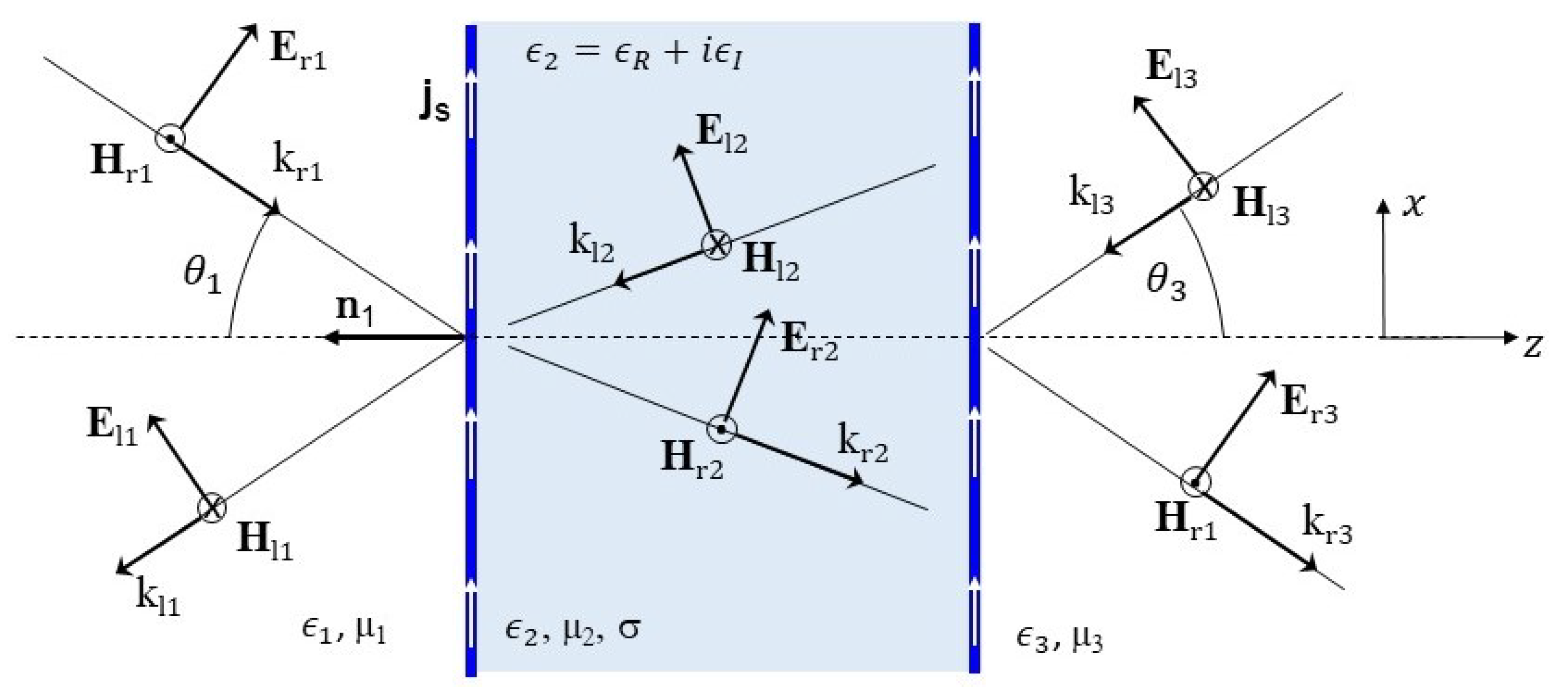
For specific calculations we will consider silver parameters: and eV, with plasma frequency [68,70] . We will assume also that . Regardless of whether the electric parameters are real or complex, the electric and magnetic fields in layer j, see Figure 1, can be written as
where and are the polarization vectors of the right and left moving fields as
The corresponding wave vectors are
For a simplified notation, we define the field phases
Thus, the field components in the j-th layer of the superlattice are
Applying the boundary condition for the electric fields at the interface , we obtain the the well-known Snell’s law
with and complex. Because of the complex nature of these quantities, it has been common to represent the electromagnetic field phases in the conductor as [67]
Here, , and , with
and
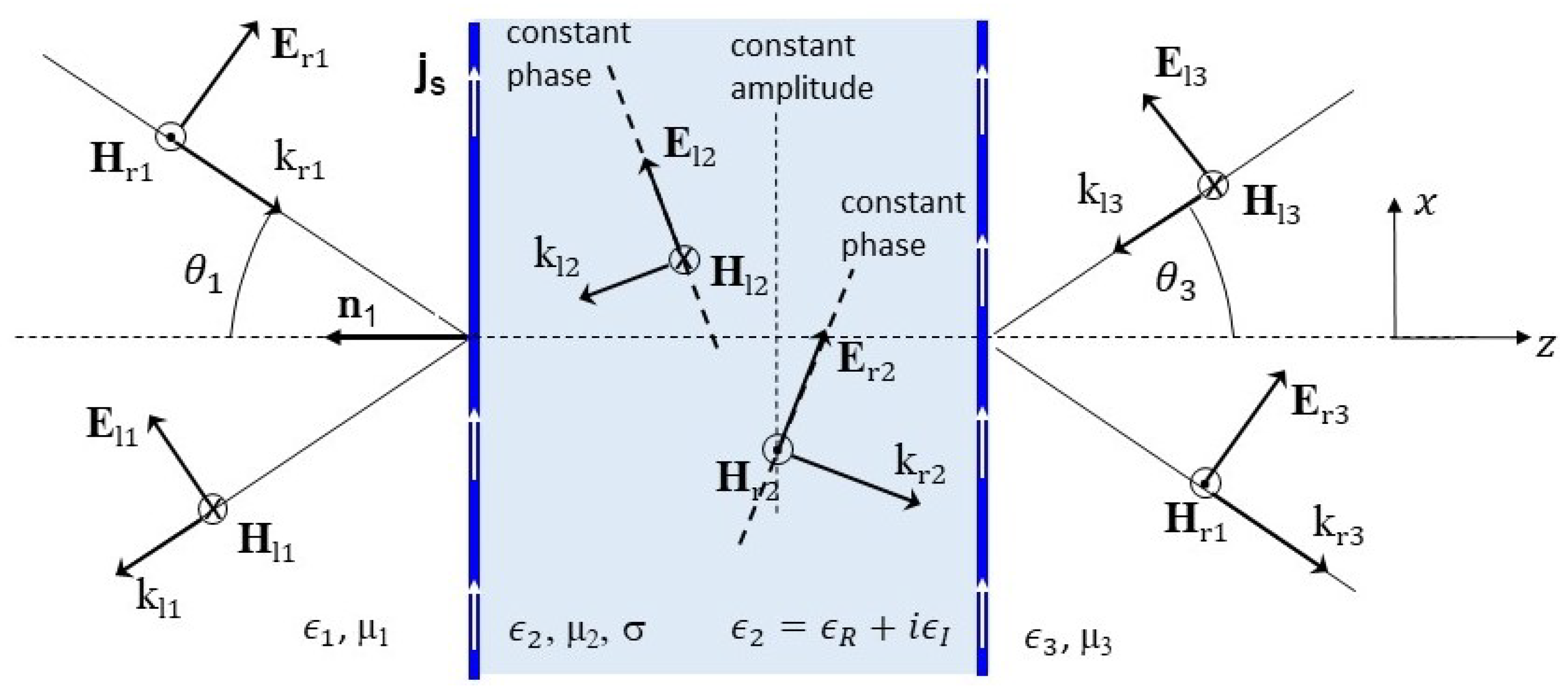
It has been also common to distinguish, in the propagation of the electromagnetic waves inside conductors, directions of constant-phase and constant-amplitude, as sketched in Figure 2. The constant-phase and constant-amplitude planes, defined by
respectively, propagate along the normals to these planes that make the angles and with the z-axis. These angles are defined by
An important and well-known consequence of the complex phases is the attenuation of the electromagnetic fields, with the ensuing loss of energy through the longitudinal and transverse currents induced by the electric fields. The rather common assumption made previously that the electromagnetic fields move along the direction determined by the true or real angle [21], neglecting the longitudinal and transverse currents, supposedly concentrated only at the surfaces, led one to write the transfer matrix that connects field vectors at the left and right of the conductor as
p and q are as defined before, , and
Note that, to keep the physical quantities finite, one of the important matrices in (13), the transfer matrix that connects the fields at the beginning and the end of the metallic layer, was written as
with a phase instead of for the left moving EMF.
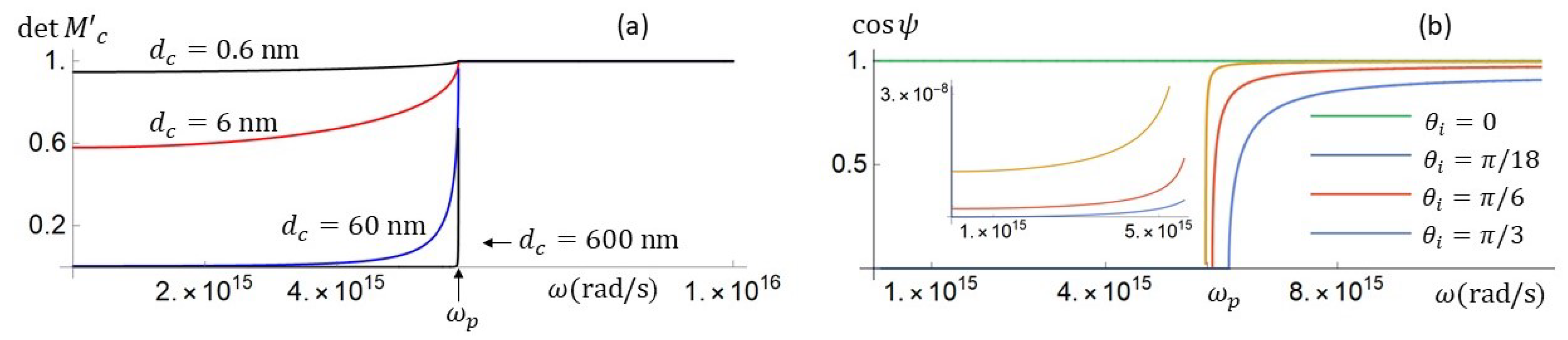
A simple way to have a measure of the lack of flux is the unimodularity of the transfer matrix. In Figure 3a, we plot the determinant of the unit-cell transfer matrix , shown in Equation (13) and used in [1], as a function of frequency , and for different values of the conducting layer width . It is clear in this figure that, for frequencies below , the determinant of is less than 1 and decreases as the layer width increases. Another quantity whose behavior needs to be clarified is the real or true angle that defines the direction of constant-phase planes. It is generally assumed that its values, measured from the normal to the interface, are small. That is true for frequencies above . However, it is not true for , as shown in Figure 3b. Except for , where is rigorously zero, is close to for and , as shown in the inset of the figure. This means that when the electric field has a large component parallel to the interface, the planes of constant-phase tend to propagate parallel to the interface, for small frequencies and finite conductivity.
In the next section, we will emphasize basic and specific differences between infinite and finite superlattice approaches. Then, in Section 4 and Section 5, we will address the lack of unitarity issue. We will present two approaches, with compatible results. We shall first consider a complex-angle approach, and in Section 5, we will present an improved real-angle approach, where (besides the true angle assumption) we will take into account explicitly the induced currents. In the complex-angle approach, we keep the complex angle and the complex wave number at the conducting layers. In this case, the unit-cell transfer matrix is automatically unimodular. In the improved real-angle approach, the induced currents account for the absorption factor and restore the flux-conservation principle.
3. Criticism and Differences with Infinite Superlattices Approaches
Given that most of the published works on metallic superlattices deal (as Yeh et al.) with a heterogeneous approach based on the Floquet theorem and the transfer matrix method, we will outline the main arguments of Yeh et al. [5,71], and we will show the implications and main differences with our approach. To frame our analysis, we will recall some properties of transfer matrices and the Bargmann representation [72].
As mentioned many times, assuming the Floquet theorem is like assuming infinite systems. One of the consequences is that it leads to dispersion relations which predict continuous subbands. Another drawback is that important physical quantities, such as the reflection and transmission coefficients, are meaningless in systems with no beginning and no end. As reflection and transmission are properties inherent to transport of electromagnetic fields, it is clear that theories built under the assumption of infinite systems have at least conceptual problems calculating these quantities, and frequently turn back to transfer matrices for finite systems.
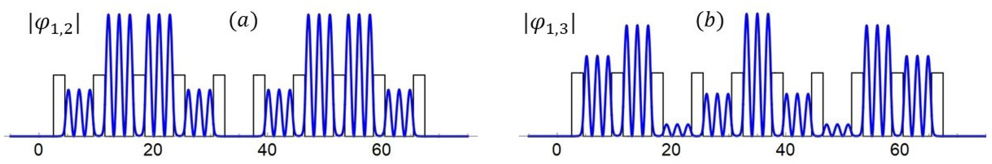
There is abundant literature on transfer matrices as tools for connecting the physical solutions with the scattering amplitudes, as well as for determining solutions of larger systems, given the single-cell solutions and the single-cell transfer matrix. There are many publications where the resonant wave functions in open superlattices have been obtained using transfer matrices of finite systems, and the important feature of these functions is that they do not fulfill the Floquet theorem. In Figure 4, we have examples of resonant functions for electrons and holes in an open semiconductor SL. See also the eigenfunctions in Figure 5b for a bounded SL. These are exact solutions for the Schrödinger equation with piecewise constant periodic potential. To obtain these functions we use transfer matrices like the one in (20), and none of these functions satisfies Floquet’s theorem. It is worth emphasizing that the single-cell transfer matrix and the n-cells transfer matrices contain no more information than the solutions of the Maxwell or the Schrödinger equation. The correctness of the model and the accuracy of the solutions are independent of the TMM. Once the single cell transfer matrix is obtained, the next step is to use the TMM to obtain solutions for a larger system.
The structure of the transfer matrices depend on the symmetries and principles present in the physical systems. Time reversal invariance and flux conservation are important properties that allow the 4 free real parameters, in a matrix of dimension 2N × 2N, to reduce to . In that case, the matrix belongs to the symplectic group. For the one-dimensional systems considered here and in other works, ; thus, the number of real free parameters is 3, and the transfer matrices belong to the group. V. Bargann [72] has shown that the transfer matrices decompose as
with the range of the parameters , , and , defined by the inequalities
It has been shown also that the group of transfer matrices, factorizes as a product of a compact and a non-compact subgroup [73]; therefore, the transfer matrices can be written as
with and symmetric and complex. It has been also shown, without any additional assumption, that given the unit-cell transfer matrix, for example,
the n cells transfer matrix is given by
where is Chebyshev polynomial of the second kind, and . This representation was, apparently, first derived by F. Abelès in 1950, and was re-derived many times in the history of the TFPS [1]. In this theory, the dispersion relation depends on the quantum numbers and of the resonant frequencies [1,61,63,65,74] and is given by
These are important quantities where the TFPS and the infinite periodic systems approach (that we refer to here as the Yeh’s approach, as briefly outlined below) differ.
Yeh et al. follow a procedure introduced by Kramers [52] in 1935 to derive an eigenvalue equation. Assuming that the electromagnetic fields in a periodic system, with period , fulfill the Bloch–Floquet theorem, it is possible to obtain the requirement
with M the unit-cell transfer matrix, and and coefficients for the right and left moving fields. From the eigenvalues equation one has
This leads to a Kronig–Penney-like [75] dispersion relation. This is not, however, the only logical outcome of this argument. The requirement (22) also has an important implication on the transfer matrices. To fulfill the Floquet theorem and the requirement (22), the transfer matrices of periodic structures must be written as
with given by the dispersion relation
when . This transfer matrix belongs to the compact subgroup mentioned above. This is known also as the empty lattice approximation [25]. It is clear that the transfer matrix that connects the field , with the field , is
These are the transfer matrices that are compatible with Floquet’s theorem, and with how some authors [4,6,7,25], who also invoke Floquet’s theorem, represent electromagnetic fields in the n-th layer of infinite periodic systems. Others use, at the same time, the dispersion relation (25) of infinite systems and the transfer matrix (20) of finite systems.
Apparently, the differences are small, but that is not really the case. The results can be quantitatively and qualitatively different, and with profound and significant departures (as those between classical and quantum theories). We will see some examples that exhibit the differences.
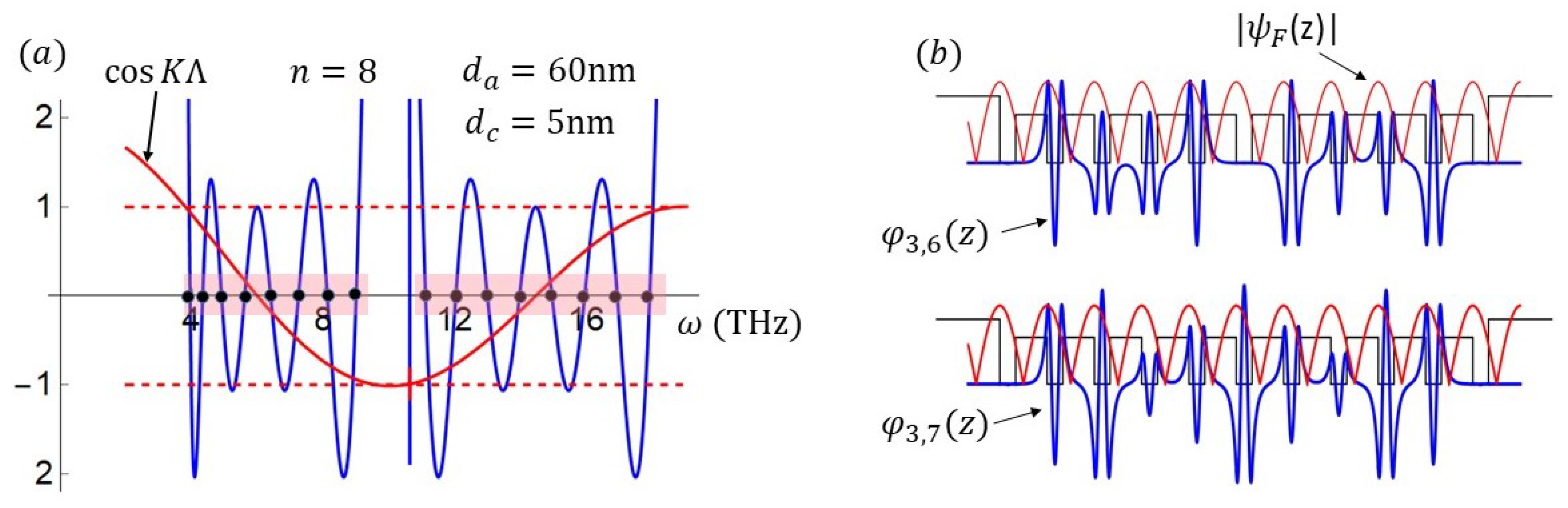
In Figure 5a, we plot the function defined in (25) and show the subbands defined by the domains (red rectangles) where this function takes values between −1 and 1. In the same figure, we have the intra-subband levels (black dots) determined by the discrete dispersion relation (21) of the TFPS. In this case, we used data for the superlattice referred to below. For open systems, the resonant frequencies are defined by the zeros of the Chebyshev polynomials . The position and widths of the discrete subbands are the same as the position and widths of the continuous subbands, and coincide in the limit , as shown in Figure 6. In Figure 5b, we show the absolute value of a Bloch–Floquet function, and the eigenfunctions and in the valence band of a superlattice. It is important to emphasize here that the eigenfunctions determined in the TFPS, based on the transfer matrices of Equation (20), do not satisfy the Bloch–Floquet theorem. Therefore, using the n-cells transfer matrix in (20) and assuming, at the same time, infinite systems is a gross inconsistency.
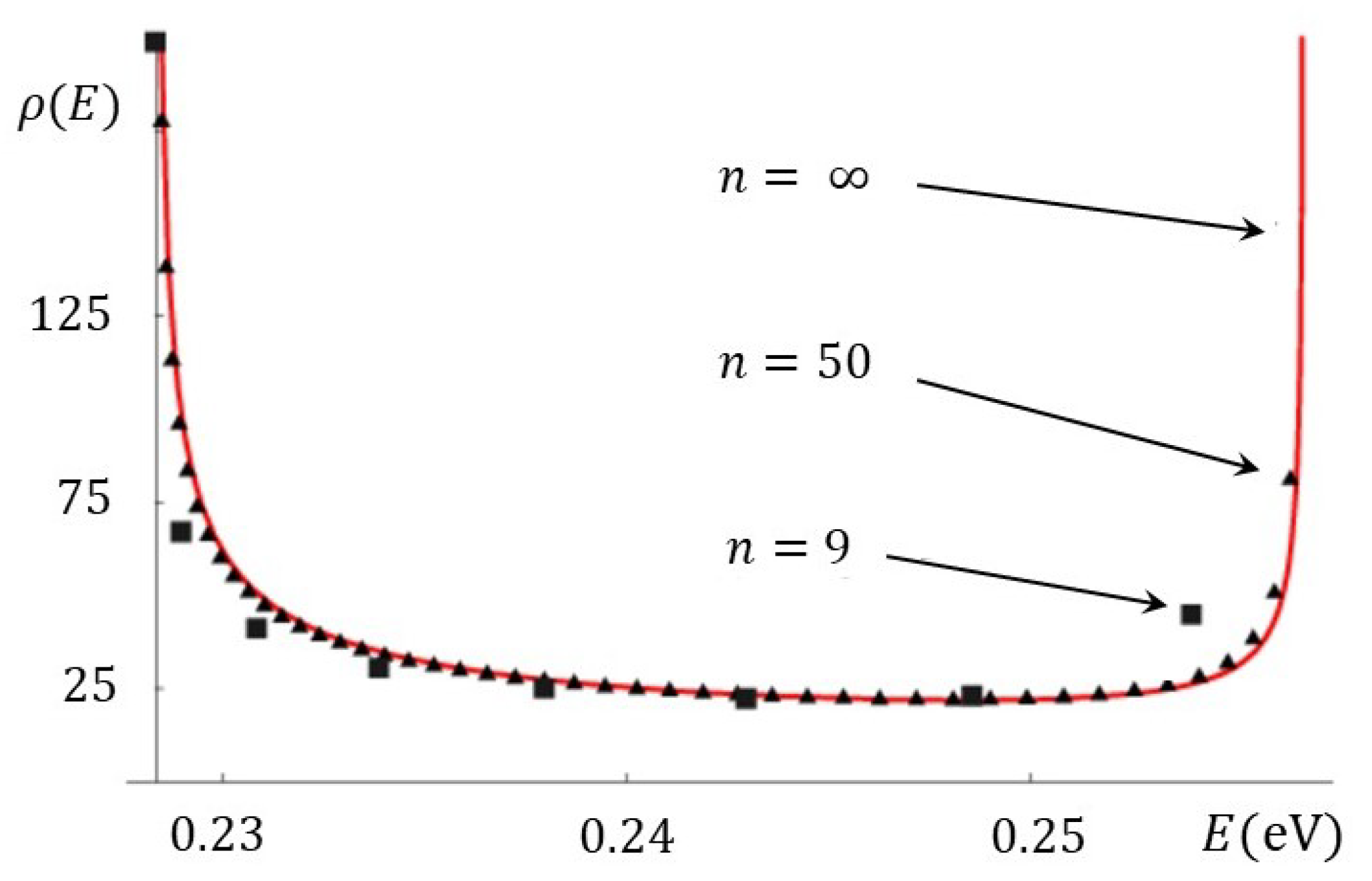
In Figure 6, we show that as the number of unit-cells n tends to infinity, the density of intra-subband levels tends to the continuous density of energy levels derived by Kronig and Penney [75] for infinite systems.
In Figure 7 and Figure 8, we compare, side by side, the predicted subbands both in the standard approach and in the TFPS. Figure 7 is for semiconductor SLs, and Figure 8 is for metallic SLs. In Figure 7, we reproduce a figure from in ref. [74] to show the subbands as functions of the widths of the wells predicted by the Kronig–Penney theory (left) and the TFPS (right), by using the same parameters for the SLs.
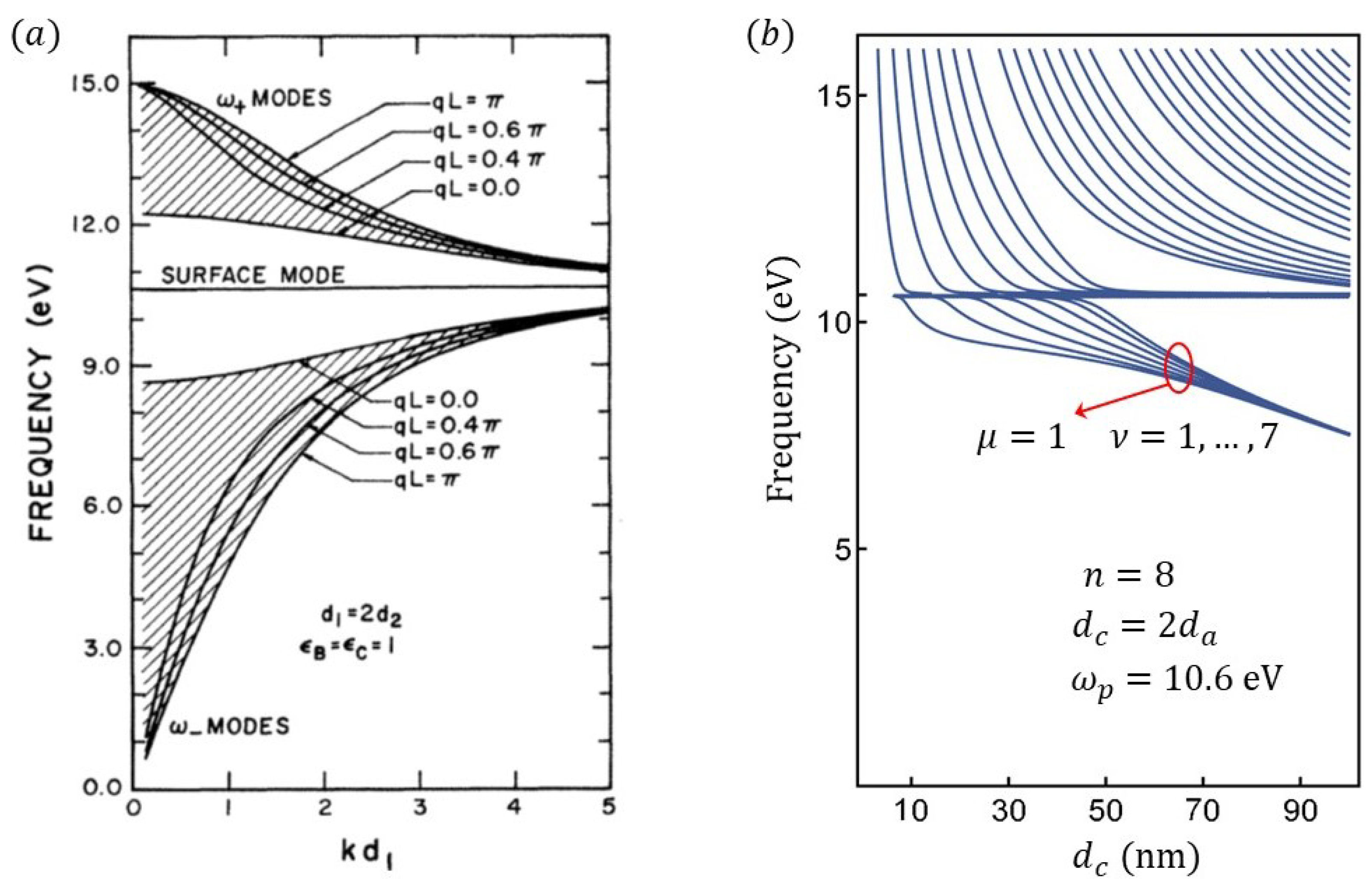
In Figure 8 we also have subbands, but now for a metallic superlattice. In Figure 8a are the subbands reported by Camley and Mills [8] for a semi-infinite superlattice, also using the Bloch’s Theorem as a basic input. Their dispersion relation is essentially as the Kronig–Penney-like relation in (25) with instead of . The various lines at the edges of the subband correspond to different values of , and should not be confused with intraband levels. In Figure 8b, we plot the subbands predicted by Equation (38) of the TFPS, for the finite SL , using the same parameters as in ref. [8]. In order to fit the screened plasma frequency of 10.6 eV in (a), we used = 2.002, instead of = 1 mentioned by Camley and Mills. We also consider the metal-layer width twice the width of the dielectric layer and plot the subbands as function of these widths. The most visible difference is in the evolution of the subband for frequencies below . We believe that the correct evolution should be downwards as in Figure 8b. The reason is simple to understand. We know from quantum theory and quantum SLs that as the widths of the wells increase, the energy eigenvalues move down in energy, as shown in Figure 7a,b. In Figure 8a,b, . It is clear that as and grow, the bands should move downward. We also know from quantum theory that as the widths of the barriers (which correspond to conductors widths) increase, the splitting of the energy levels and the bands themselves tend to disappear.
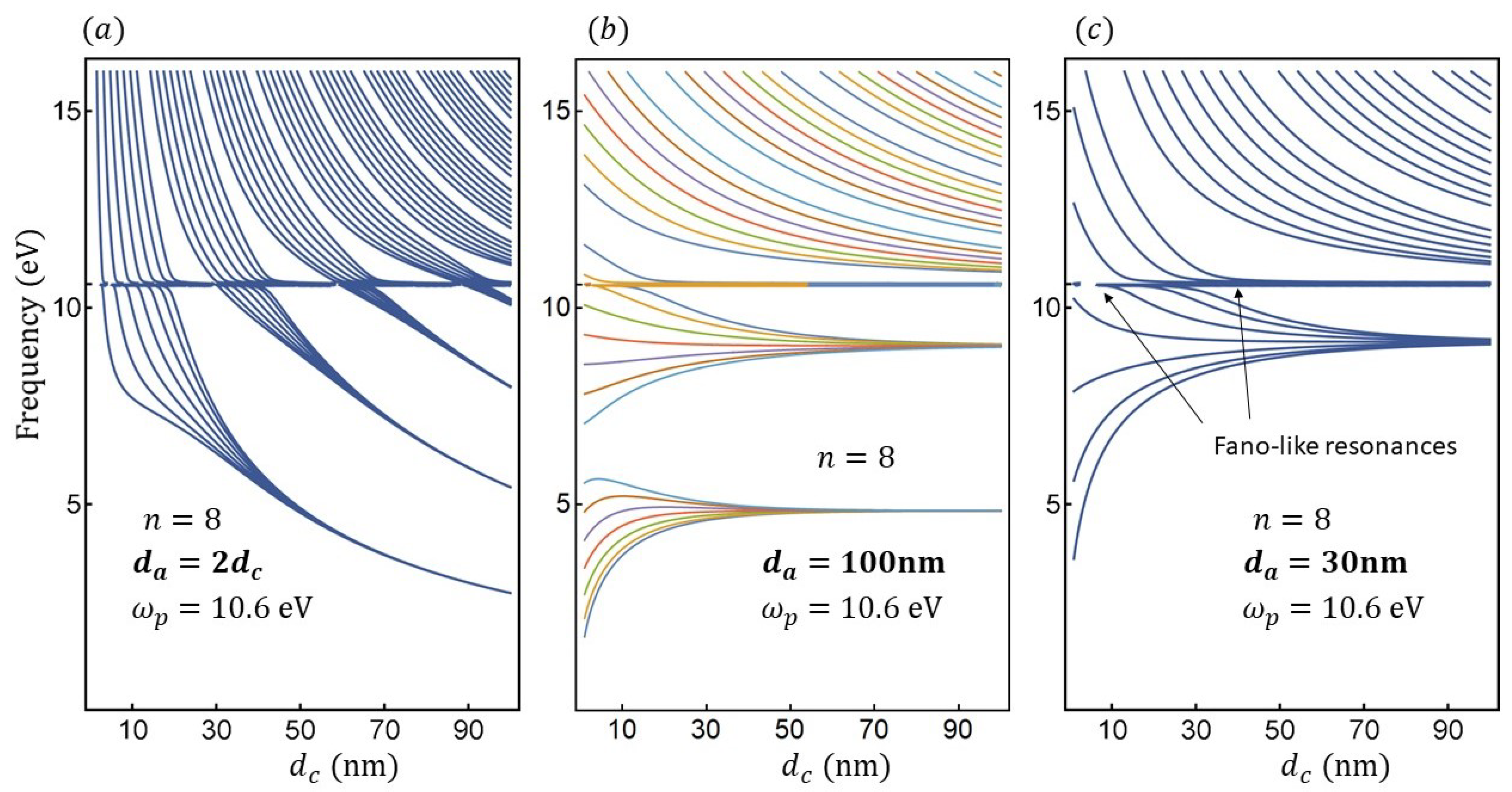
Other evolutions of the resonant frequencies are possible to obtain by choosing other relationships for the metallic superlattice parameters. In Figure 9, we consider three different relationships for the dielectric and conductor widths. In Figure 9a, both and grow, with always twice larger than ; Figure 9b, is fixed and equal to 100 nm, and is smaller varying from 0.01 to 100 nm. In Figure 9c, is kept fixed and equal to 30 nm, and smaller and larger than , varies between 0.01 nm and 100 nm. Notice a Fano-like behavior at .
In this section, we have shown the consequences that imposing the Bloch Theorem has on the TMM and on the dispersion relations. This assumption is present in practically all the published works on infinite and semi-infinite metallic superlattices, even in quite recent publications, for example, Markos and Soukoulis’ book [76] and in the numerous papers published by Iakushev et al. [77], all of them rely on the approach of Yeh et al. We have shown that the most transcendental effects related to finiteness are, on one side, the possibility or not of defining quantities as the transmission and reflection coefficients and, on the other, very important from the point of view of plasmonic resonance applications, the ability or not to determine intra-subband frequency resonances. These are essential differences and at variance with our approach.
4. Complex-Angle Approach
Even though the recognition of constant-phase and constant-amplitude planes for EMFs inside conductors helps one to understand important properties of these fields in this kind of media, there is no need, in principle, in the transfer matrix approach to assume that the EMWs move along the real or true angle. In fact, we can equally well work with the complex angle (to be compatible with the principle of flux conservation) and we can determine the transmission and reflection coefficients of metallic superlattices for frequencies below and above the plasma frequency . In this section, we will present this complex-angle approach and obtain some results.
Te boundary conditions at the interface , at , are expressed by the following relation,
where the subindices and mean evaluation at and , in the . The parameters and are
Similarly, the boundary conditions at the interface , where , lead to
Here,
The matrices and are formally similar to the well-known matrices of Fresnel amplitudes. In [1], we had instead of . In the following, we will omit the subindices for the matrices. The relation between the electromagnetic fields at the left and right hand side of the conducting layer is
where , when the conducting layer width is . Multiplying the matrices we obtain the transfer matrix for a conductor layer
with
Therefore, the transfer matrix of the unit cell , whose layer widths are , , and , is
Here,
Note that in this representation, both flux and time reversal invariance are preserved. This is because by keeping the complex angle, all the components of the electromagnetic field, i.e., the transmitted, reflected, and absorbed components, are fully taken into account. As will be seen below, the transmission coefficients in the high frequency domain, for are exactly the same as in the real-angle approach. However, in the optical regime, where , some properties remain, but others like the apparent parity effect and transparency, disappear.
As was pointed out in ref. [1], to determine the scattering properties of the electromagnetic fields through metallic superlattices, using the theory of finite periodic systems [61,63,65,78,79] outlined there, it is essential to know the unit-cell transfer matrix, and by applying the general formulas of the TFPS one can straightforwardly obtain the transmittance and reflectance through metallic superlattices, as well as to determine the resonant band structure of the surface plasmon polaritons. The transmission and reflection coefficients of a superlattice with n unit cells are obtained from
where
and the Chebyshev polynomial of the second kind and order n, evaluated at the real part of . It is worth recalling here a statement in ref. [63], and others afterwards, “…the polynomials comprise the whole information of the complicated phase interference processes, originating in the multiple reflections along the periodic system, and of the system’s size L ( in the growing direction) reflected in the order of the polynomial.” The resonant frequencies and band widths are determined by the resonant dispersion relation [1,63,65]
and are the quantum numbers of the resonant frequencies , of the -th resonance of the band . Generally = 1, 2, 3, … and = 1, 2, …, .
In terms of the physical quantities defined in this approach, the resonant dispersion relation is
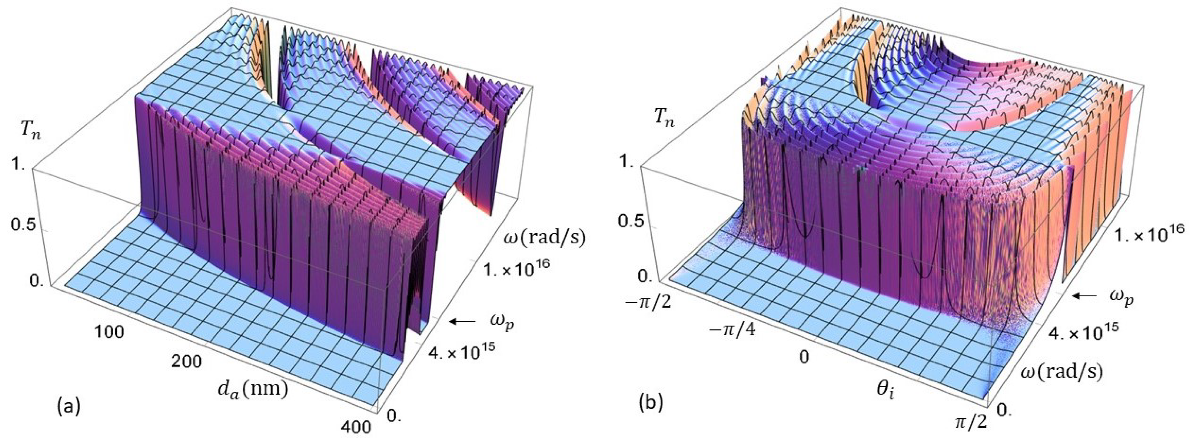
In Figure 10 and Figure 11, we show the trends of the transmission coefficient as function of the frequency and of the layer widths. The frequencies vary from 0 to Hz, i.e., frequencies below and above . In Figure 10, the transmission is plotted as a function of the dielectric-layer width , while in Figure 11 as a function of the conducting layer width . For these examples and the others in this report, we consider air in the dielectric layers and silver in the metallic ones.
For frequencies above , which for silver are of the order of Hz, the transmission coefficients are, in all cases, exactly the same as those in the real-angle approach of ref. [1]; however, for frequencies below , the results are different. Below the plasma frequency, we have now narrower bands and thinner resonant states, implying larger mean-life times for the resonant states and larger tunneling times for electromagnetic waves whose frequencies are resonant. In electronic and electromagnetic field transport, the transmission resonances result from a complex and coherent superposition of electromagnetic fields facilitated by the superlattice periodicity. These coherent superposition of fields imply the participation of collective photon-driven electron oscillations, the so-called plasmon polaritons. The long-standing resonances correspond to localized plasmon polaritons. From Figure 10 and Figure 11, it is clear that the increase in and the increase in have opposite effects on the extent of the complete-reflection domain at low frequencies. While increasing the reflection domain diminishes, increasing the complete-reflection domain grows.
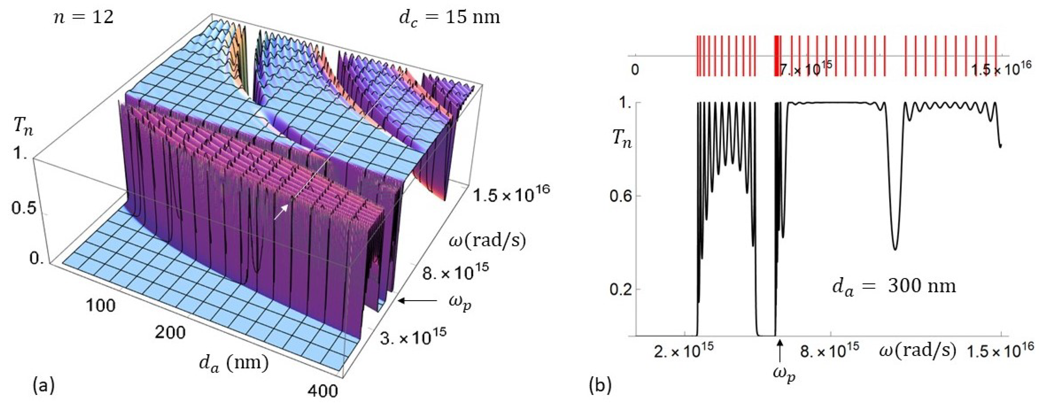
In Figure 10a,b, we have the transmission coefficient as a function of and , for a metallic superlattice with , nm and . In Figure 10a, we see that as is increased, the bands move to lower frequencies, as in quantum systems when quantum-well widths increase, and the band widths become narrower. To visualize the resonant-band features better, we plot in Figure 10b the transmission coefficient evaluated at nm, indicated with the white arrow in Figure 10a. We also plot, in the upper part of this graph, the resonant levels predicted by Equation (39). These resonances, that result from complex coherent superpositions of multiple reflected and transmitted fields plus collective electron oscillations are, in general, extended electromagnetic states, with large mean-life time, nevertheless the collective electron oscillations occur mainly at the surfaces of the metallic layers. These surface excitations correspond to the so-called localized surface plasmon polaritons.
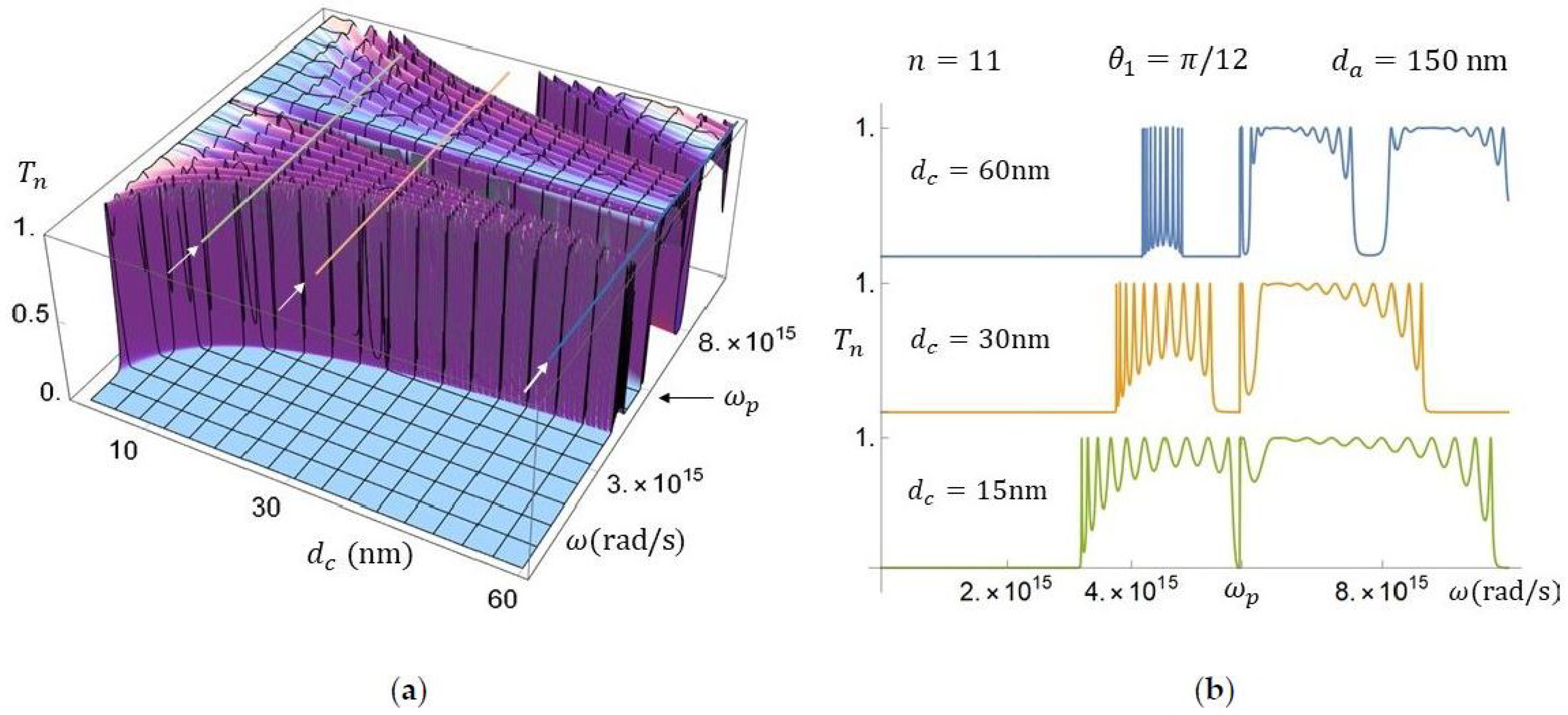
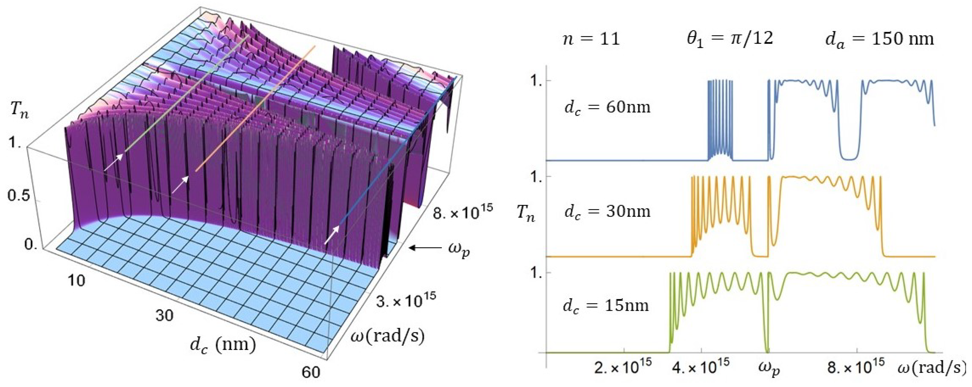
In Figure 11a,b, we have the transmission coefficient as a function of and , for a metallic superlattice with , nm, and . In this example, we have also a resonant transmission band for . In Figure 11a, we see that the band width diminishes as the conductor layer increases. To visualize the resonant behavior better, we plot in Figure 11b the transmission coefficients for nm, nm, and nm. They correspond to those layers’ widths indicated with white arrows in Figure 11a. Here, the resonant transmission bands are also within the visible light domain.
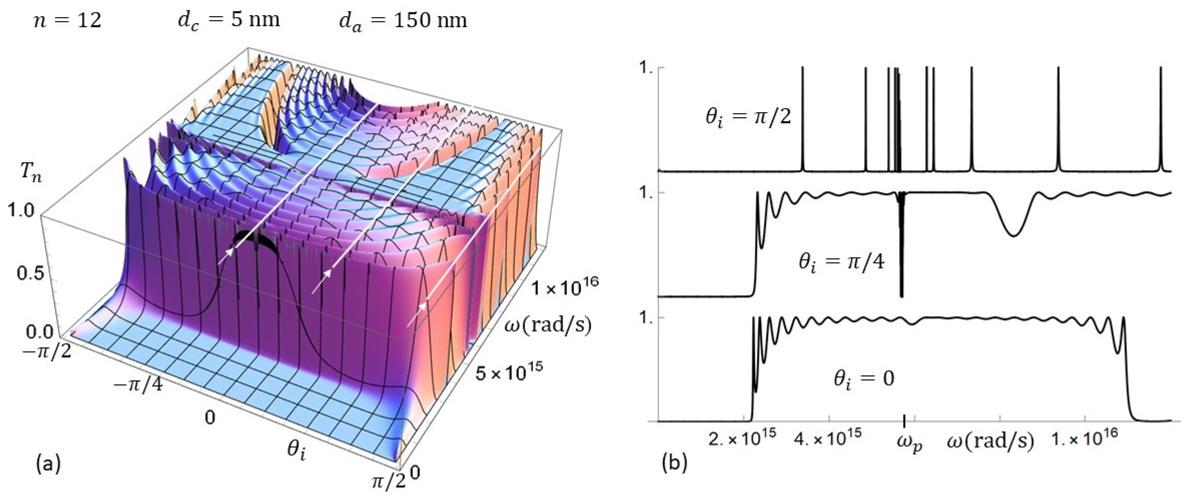
The resonances positions and band widths depend not only on the layers’ widths, but also depend strongly on the incidence angle. In Figure 12a,b, we plot the transmission coefficient as a function of and , for a metallic superlattice with , nm, and nm. In Figure 12b, we see the transmission coefficient for , , and , which correspond to those values of indicated with white arrows in Figure 12a. It is clear from these graphs the enormous qualitative and quantitative differences in the transmission coefficient and the resonant features as functions of the incidence angle. As was shown of ref. [1] the transmission resonances become delta type when the incidence angle is equal or even close to .
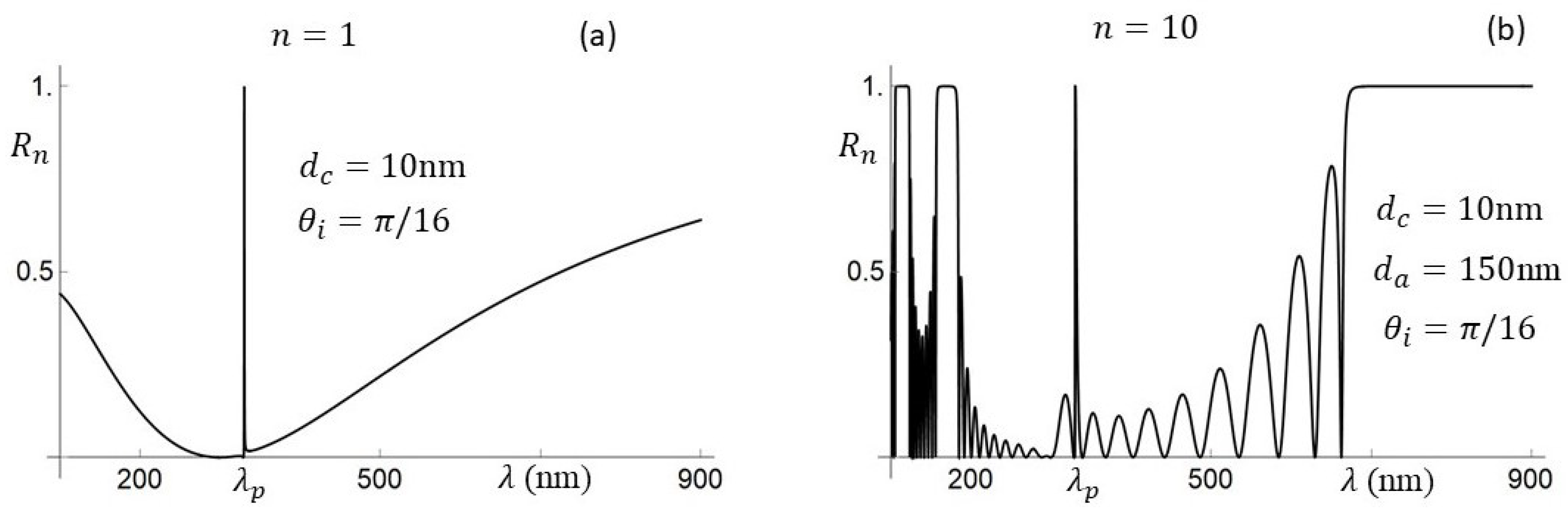
As , we generally omit the calculation of the reflection coefficient. Nevertheless, it may be helpful to visualize its behavior, in particular, the effect that the number of layers may have in the optical regime. In Figure 13, we have the reflection coefficient of a single silver layer (Figure 13a) and for a superlattice with . It is clear that the superlattice not only imply resonances, but also well defined bands of complete reflection and, for some configurations, of complete transmission.
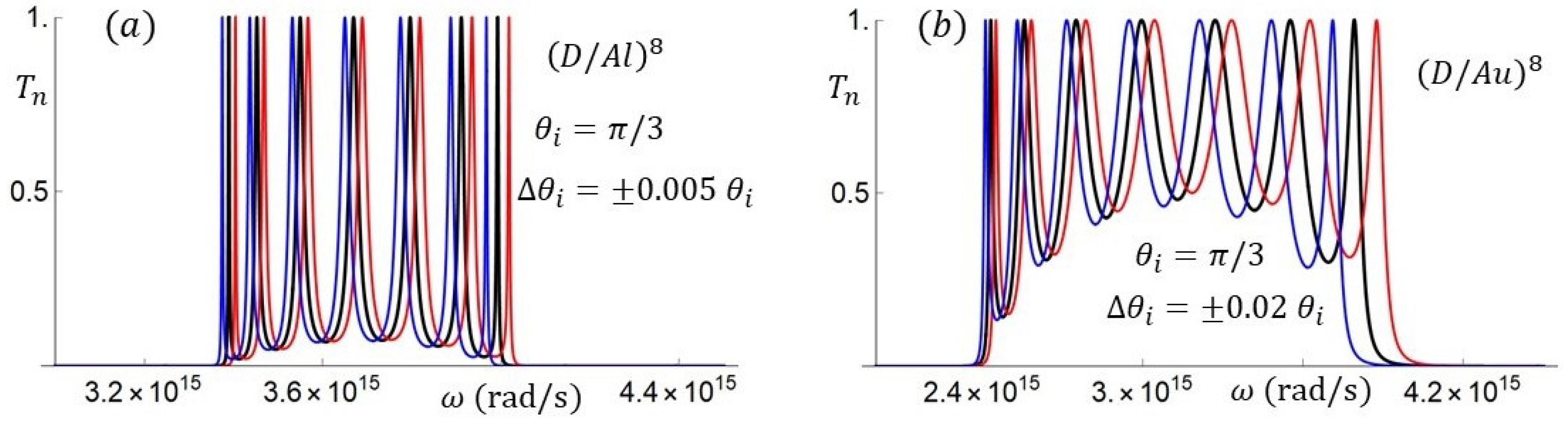
The resonances of the transmission coefficients, or dips of the reflection coefficients, many of which are unveiled in this approach, are generally identified as surface plasmon resonances (SPRs). Knowing the frequencies of these resonances, it is useful for applications such as biosensors [80,81], which are based on SPRs and their sensitivity to changes in device parameters, such as the incidence angle. In Figure 14, we plot the transmission coefficients for and superlattices when the incidence angle is (black curves). In Figure 14a the changes in the incidence angle are (red/blue curves), while in Figure 14b the changes are (red/blue curves).
Playing with the superlattice parameters, the incidence angle and the electromagnetic field polarization, we can obtain an endless variety of optical responses for the electromagnetic fields that fall upon the surface of a metallic superlattice.
In the next section, we will return to the real angle approach and compare with the results of this approach.
5. Improved Real-Angle Approach
As explained before, the lack of flux in the real-angle approach indicates the need to include the induced currents at the metallic layers. We will include the induced currents, assume that inside the conductor the electromagnetic waves move along the real angle (also called true angle) of the constant-phase planes, and finally impose the conservation of flux. It is well known that the inclusion of currents, induced in the metallic layers and responsible of the plasmonic resonances, is compatible with the Maxwell equation
which contemplates the possibility of induced currents; the plasmon oscillations, which in perfect conductors are localized at the surface but in lossy conductors respond to the local field. We will assume that in each layer j we have currents, induced be the right and left moving fields, whose magnitudes are proportional to the magnitude of the local electric fields
Here, the amplitudes and are proportional to the conductivity and to an attenuation factor determined below, that accounts for the loss of energy. Taking into account the surface currents
at , and
at , for the boundary conditions. The transfer matrix of the conducting layer that connects the field vectors at its left and right hand sides becomes
with , , . The matrix-elements
and the transfer matrix , which connects the electromagnetic fields at the far left () and far right () inside the metallic layer, is written as mentioned before as
The attenuation factor depends on the attenuation constant p and the conducting layer , and a transfer matrix that accounts for the phases and that are gained by the electromagnetic fields that propagate along the real angle , with wave number q.
It is easy to verify that up to a phase , with negligible effects on the results as shown below, the requirement of flux conservation implies that
As , we can define an absorption or flux-loosing factor a such that , thus the attenuation factor
where is the skin depth that provides the magnitude of the induced currents and the amount of flux lost exciting the plasmonic resonances. Given the transfer matrix it is easy to obtain the unit-cell transfer matrix
where and , , … are the matrix elements of . Having the unit-cell transfer matrix, we can apply the theory of finite periodic systems [61,63,65]. The transmission and reflection coefficients of a superlattice with n unit cells are obtained from
where
with the Chebyshev polynomial of the second kind and order n, evaluated at the real part of .
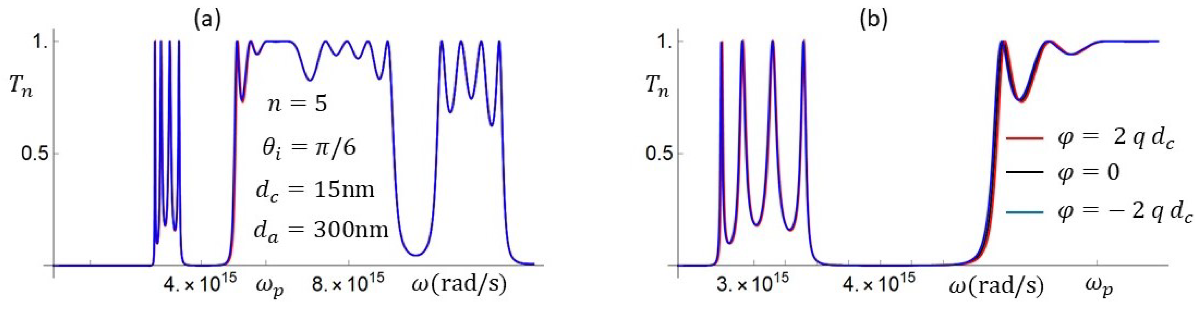
In Figure 15a,b, we plot the transmission coefficients with the same parameters as in those of Figure 10a and Figure 12b. The agreement below and above the plasma frequency is excellent. However, at and close to , the behavior is different. For the graphs in Figure 15, we consider the phase . This phase accounts for the effective phase gain due to the multiple internal reflections. As shown in Figure 16, the effect of is practically negligible and null for frequencies above . Figure 16b is just a zoom of Figure 16a.
For the purpose of calculating only transmission and reflection coefficients there is no advantage in using this real-angle approach, compared with the more accurate complex-angle approach. However, the improved real-angle approach does inform on the role that the induced currents play in the energy absorption phenomenon, for frequencies below , which implies the optical domain.
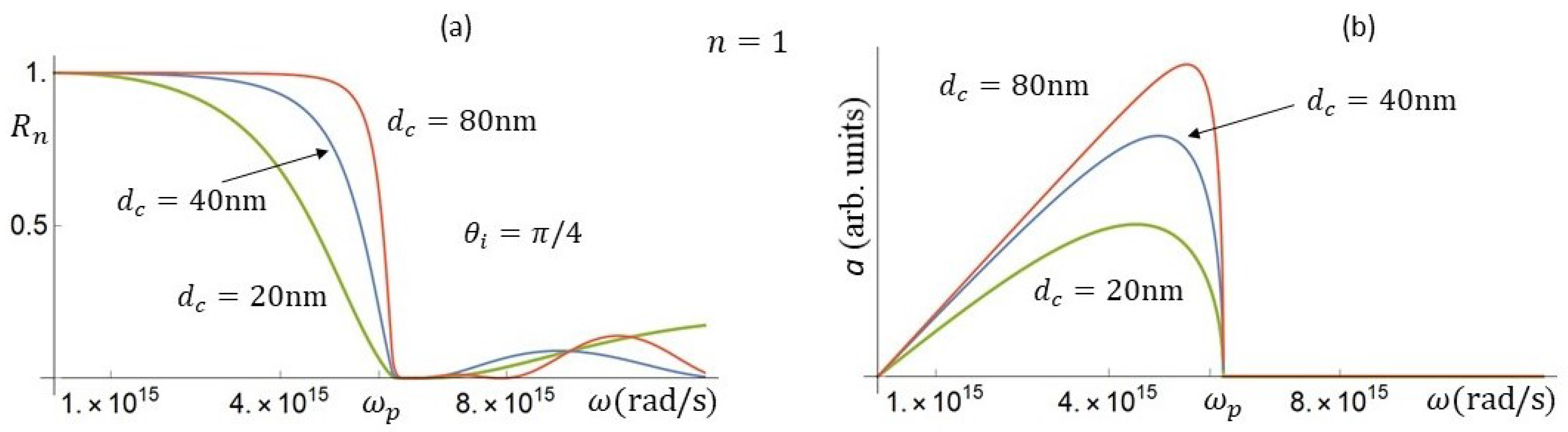
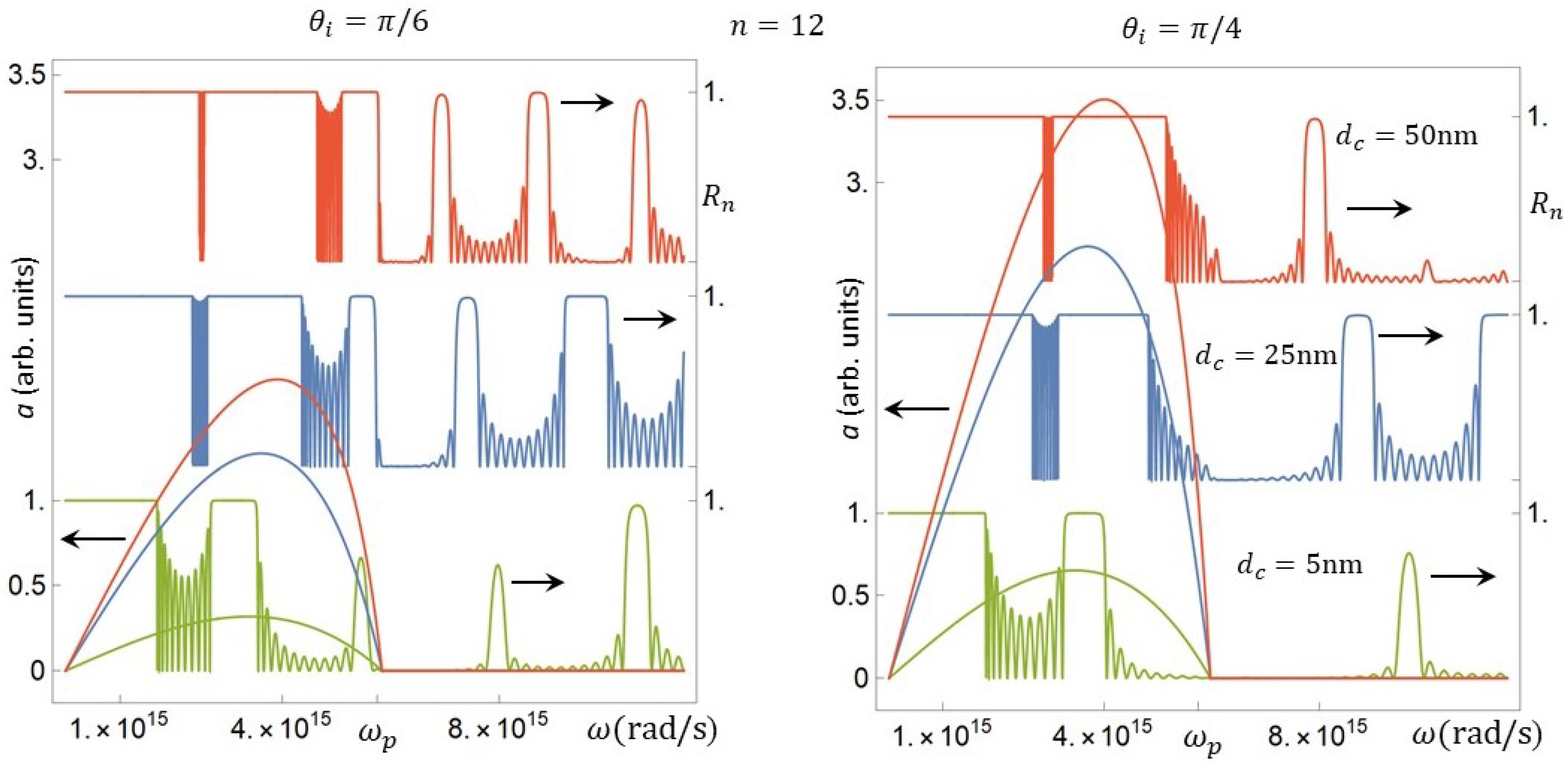
In Figure 17a, we plot the reflection coefficient of a single layer of silver for different thicknesses, and in Figure 17b, the absorption factor a, which represents the strength of the absorbed flux exciting the plasmon oscillations. These currents attenuate the transmission and enhance the reflection coefficient. As shown in Figure 17b, the absorption factor a grows when the conducting layer width increases. In Figure 18, we show the effect of the incidence angle and conducting layer width on the absorption factor a and on the reflection coefficient for a superlattice with and dielectric width nm. As shown by these results, the absorption factor is very sensitive to the incidence angle and, of course, to the conducting layer width. We see that increasing the incidence angle from to the absorption a, therefore the induced currents, grows by a factor of 2.
Before we conclude this section, let us see the resonant dispersion relation, and in particular the dispersion relation predictions below the plasma frequency . As mentioned before, the resonant dispersion relation derived in the theory of finite periodic systems is [1,63,65,74]
In terms of the physical quantities defined in this approach, this relation (for ) becomes
with
A quantity that is also useful is the imaginary part of , which can be written as
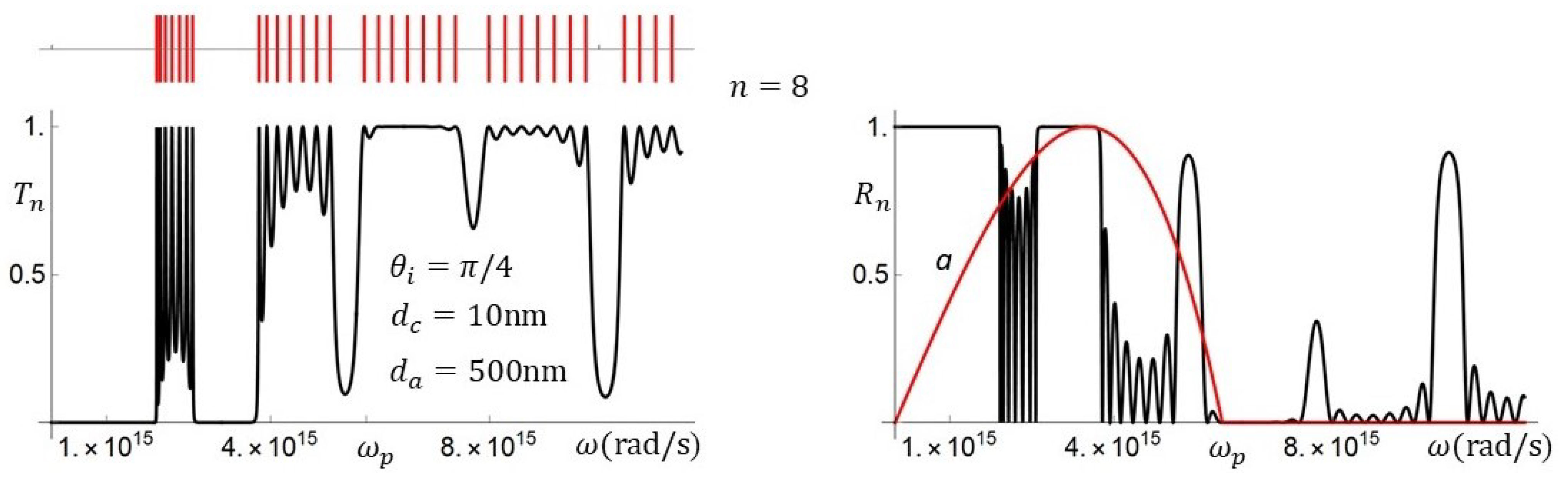
In Figure 19, we plot the transmission and reflection coefficients, together with the absorption factor and the resonances and bands predicted by the dispersion relation. These graphs show not only the ability of this approach to calculate the essential quantities like the transmission and reflection coefficients, and the accurate prediction of the resonance frequencies spectrum, but also the appropriateness of this approach to determine (through the absorption factor a) the strength of the absorbed energy consumed to excite the plasmonic polaritons as response to the incident electromagnetic field. This information provides additional insight in the physics of metallic superlattices.
In the applications based on the response of metallic structures to electromagnetic fields, the response to electromagnetic pulses might be of interest. As the details of the electromagnetic fields inside the metallic structure is a bit complex, we will present here just a couple of results.
6. Reflection and Transmission of Gaussian Pulses by Metallic Superlattices
As illustrative examples of use of the above mentioned results, we will present the transmission and reflection of an electromagnetic pulse by a metallic superlattice. If the electromagnetic pulses are Gaussian wave packets, they are defined by
where defines the peak of the Gaussian pulse and its position at . For , the z component of the electromagnetic field is written as
where and are the matrix elements of the n-unit cells transfer matrix . For , with the SL unit cell length, the electromagnetic field is written as
The possibilities of total, partial, or zero reflection of an electromagnetic pulse by metallic superlattices are important for applications and strongly determined by the transmission or reflection coefficients of each component of the Gaussian packet, in particular by the domain of frequencies where the wave packet is defined. Therefore, the transmission coefficients for the Gaussian pulse components are different. This difference manifests also in the shape of the reflected and transmitted pulses, as shown in the lower panels. In the figure, we plot the z-components as functions of z only. We also assume that the fields are in parallel polarization and the incidence angle is .
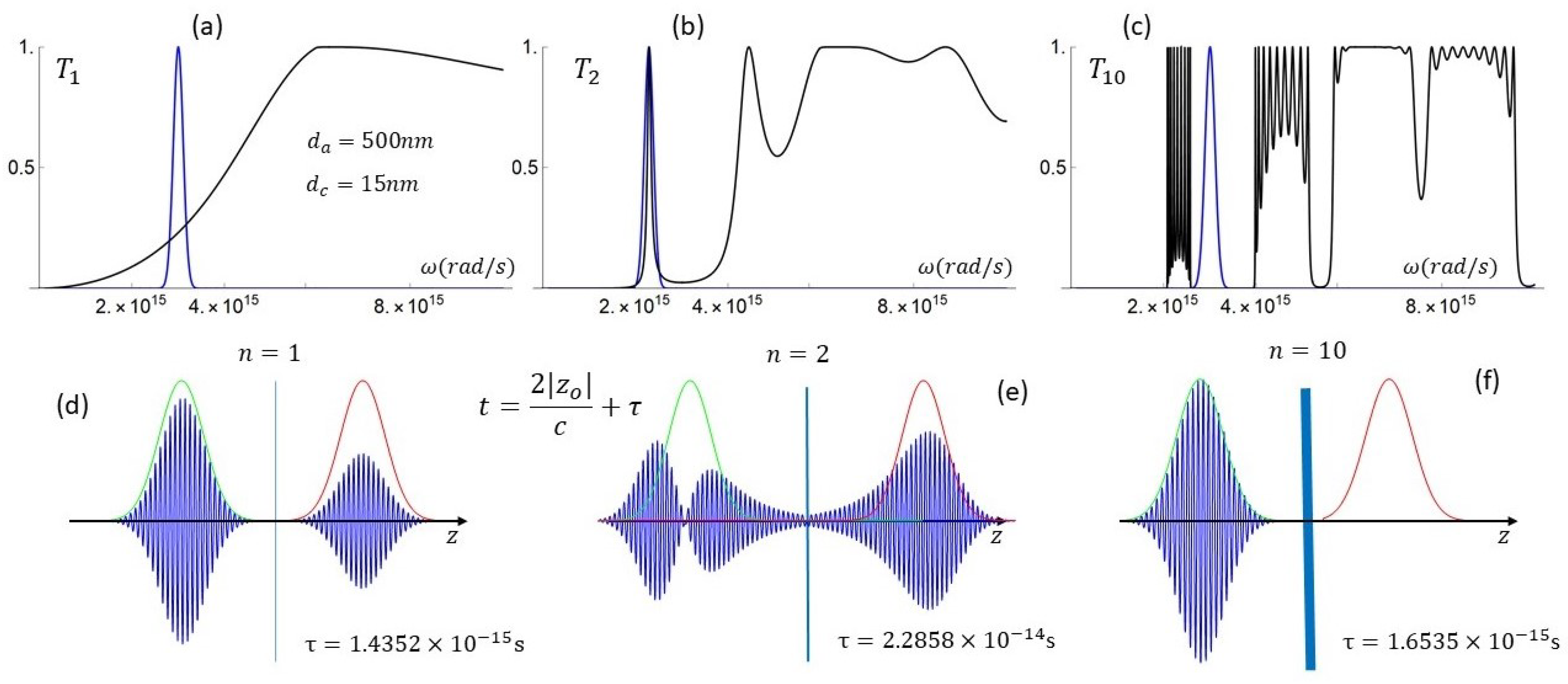
To visualize the effect of the metallic SL on a Gaussian pulse, we consider three cases where the Gaussian packets are similar, but the characteristics of the domain of frequencies where they are defined are different, and the number of unit cells in the metallic SLs is different. The number of unit cells in (a–c), is 1, 2, and 10, respectively.
In Figure 20, the transmitted and reflected wave packets are shown at , assuming that the fields outside the SL move with velocity c, and the centroid with wavenumber spends a time equal to the phase time inside the SL [82,83]. In the lower panels, we also have the envelopes of the wave packets at , green, (in position ) and at , red. The green and red Gaussian curves define the positions at which the reflected and transmitted packets should be found if is truly the tunneling or reflecting time. In each case, the tunneling time of the packet peaks is indicated. The prediction is correct, as was shown in other papers [78]. In case (b), and slightly in case (a), the asymmetry of the tunneling times implies that the components of one tail (those with smaller frequency) move faster than those in the other tail. For this reason, in order to plot the whole transmitted and reflected packets in case (b), we increase the distance .
As the scattering process is different for each wave packet component , the wave packets are, generally, distorted, unless the whole wave packet is defined in a frequency domain such that almost all components have the same transmission coefficients. This is the case in Figure 20c, where the wave packet is defined in a gap, with 0, being thus almost completely reflected. In Figure 20a,b, because of the frequency domains, the wave packet in (a) is partially transmitted and partially reflected. The wave packet in (b), defined at a resonance, is strongly distorted. The components close to the Gaussian peak are transmitted while those in the tails are reflected.
7. Conclusions
We have shown that the anomalous results and apparent parity effects reported in [1], are consequences of the common assumption that electromagnetic fields move along the direction of propagation of the constant-phase planes, the finiteness requirement, and the neglect of the induced currents. We have shown that these assumptions imply a lack of unitarity related to the underlying phenomena of absorption and loss of energy. To cure this problem, we introduced two approaches: On the one hand, we have shown that by keeping the complex angles, the principle of flux conservation is fully satisfied, above and below . The complex-angle approach presented here preserves all the information of the scattering process in the metallic superlattice, and sheds light to improve the formalism when the real angle assumption is made. Thus, we considered that we must include currents, induced by the right and left moving fields, whose magnitudes are proportional to the magnitude of the local electric fields. We then fixed the proportionality constants by imposing the flux conservation requirement on the transfer matrices, which were built under the assumption that fields move along the real angle. In this way, the flux-loosing factor was obtained, and the attenuation factor determined. We end up with an improved approach, with new Fresnel and transmission coefficients, fully compatible with those of the complex-angle approach. The improved approach also allows one to evaluate the magnitude of the induced currents and the absorbed energy, as functions of frequency and the superlattice parameters. We have shown that within this approach, intra-subband plasmon resonance frequencies can be determined. This may be important in applications, specifically for those applications in biosensors based on this type of resonance. We also presented results of the response of metallic superlattices to electromagnetic pulses and wave packets especially in the optical domain. We calculate the reflection and transmission coefficients as well as the phase time . We show that the predicted space-time positions agree extremely well with the actual positions of the wave packet centroids.
Funding
This research received no external funding.
Institutional Review Board Statement
Not applicable.
Informed Consent Statement
Not applicable.
Data Availability Statement
Not applicable.
Acknowledgments
The author acknowledges partial APC funding by Photonics, and critical reading of the manuscript by H. P Simanjuntak and A. Robledo-Martinez.
Conflicts of Interest
The author declares no conflict of interest.
References and Note
- Pereyra, P. Photonic Transmittance in Metallic and Left Handed Superlattices. Photonics 2020, 7, 29. [Google Scholar] [CrossRef]
- Levin, M.L. The propagation of a plane electromagnetic wave in a periodical layered medium. J. Tech. Phys. 1948, 18, 1399. [Google Scholar]
- Tamm, M.L.; Ginzburg, V.L. Theory of electromagnetic processes in a layer core. Izv. Akad. Nauk SSSR Ser. Fiz. 1943, 7, 30. [Google Scholar]
- Ritov, S.M. Electromagnetic properties of a finely stratified medium. J. Tech. Phys. 1956, 2, 466. [Google Scholar]
- Yeh, P.; Yariv, A.; Hong, C.-S. Electromagnetic propagation in periodic stratified media. I. General Theory. J. Opt. Soc. Am. 1977, 67, 423. [Google Scholar] [CrossRef] [Green Version]
- Nkoma, J.S. Surface Phonon in Semi-Infinite Polaritons Semiconductor Superlattices. Phys. Stat. Sol. 1987, 139, 117. [Google Scholar] [CrossRef]
- Haupt, R.; Wendler, L. Dispersion and Damping Properties of Plasmon Polaritons in Superlattice Structures. Solid. Stat. Commun. 1987, 142, 423–435. [Google Scholar] [CrossRef]
- Camley, R.E.; Mills, D.L. Collective excitations of semi-infinite superlattice structures: Surface plasmons, bulk plasmons, and the electron-energy-loss spectrum. Phys. Rev. B 1984, 29, 1695. [Google Scholar] [CrossRef]
- Lambin, P.; Vigneron, J.P.; Lucas, A.A. Electron-energy-loss spectroscopy of multilayered materials: Theoretical aspects and study of interface optical phonons in semiconductor superlattices. Phys. Rev. B 1985, 32, 8203. [Google Scholar] [CrossRef]
- Xue, D.; Tsai, C.-H. Plasmon-Polariton modes and optical properties of metallic superlattice. Sol. Stat. Commun. 1985, 56, 651. [Google Scholar] [CrossRef]
- Wallis, R.F.; Szenics, R.; Quinn, J.J.; Giuliani, G.F. Theory of surface magnetoplasmon polaritons in truncated superlattices. Phys. Rev. B 1987, 36, 1218. [Google Scholar] [CrossRef] [PubMed]
- Haupt, R.; Wendler, L. Damping of polaritons in finite semiconductor superlattices. Phys. Rev. B 1984, 29, 1695. [Google Scholar] [CrossRef]
- Mochan, L.; Del Castillo-Mussot, M. Optics of multilayered conducting systems: Normal modes of periodic superlattices. Phys. Rev. B 1988, 37, 6763. [Google Scholar] [CrossRef]
- Mills, D.L. Collective excitations in superlattices. Top. Appl. Phys. 1989, 66, 13. [Google Scholar]
- Trutschel, U.; Golz, M.; Abraham, M. Generalized Transfer-Matrix Description of the Optical Properties of Spatially Dispersive Periodic Metal Multilayers. Phys. Stat. Sol. 1989, 151, 383. [Google Scholar] [CrossRef]
- Sheng, J.-S.; Lue, J.-T. Resonant Reflectance Dips Induced by Coupled Surface Plasmon Polaritons in Thin Metal-Film/Dielectric Superlattices. Appl. Phys. A 1992, 55, 537. [Google Scholar] [CrossRef]
- Nazarov, V.U. Bulk and surface dielectric response of a superlattice with an arbitrary varying dielectric function: A general analytical solution in local theory in the long-wave limit. Phys. Rev. B 1994, 49, 17342. [Google Scholar] [CrossRef]
- Pendry, J.B. Photonic band structure. J. Mod. Opt. 1994, 41, 209. [Google Scholar] [CrossRef]
- Quinn, J.J. Bulk and surface plasmons in solids. Nucl. Inst. Meth. Phys. Res. B 1995, 96, 460. [Google Scholar] [CrossRef]
- Lyndin, N.M.; Salakhutdinov, I.F.; Sychugov, V.A.; Usievich, B.A.; Pudonin, F.A.; Parriaux, O. Long-range surface plasmons in asymmetric layered metal-dielectric structures. Sens. Actuator B 1999, 54, 37. [Google Scholar] [CrossRef]
- Inan, U.S.; Inan, A.S. Electromagnetic Waves; Prentice Hall: Upper Saddle River, NJ, USA, 1999. [Google Scholar]
- Botten, L.C.; Nicorovici, N.A.P.; Asatryan, A.A.; McPhedran, R.C.; de Sterke, C.M.; Robinson, P.A. Formulation of electromagnetic scattering and propagation through gating stacks of metallic and dielectric cylinders for photonic crystal calculations. Part I. Method. J. Opt. Soc. Am. A 2000, 17, 2165. [Google Scholar] [CrossRef]
- Botten, L.C.; Nicorovici, N.A.P.; Asatryan, A.A.; McPhedran, R.C.; de Sterke, C.M.; Robinson, P.A. Formulation of electromagnetic scattering and propagation through gating stacks of metallic and dielectric cylinders for photonic crystal calculations. Part II. Properties and Implementation. J. Opt. Soc. Am. A 2000, 17, 2177–2190. [Google Scholar] [CrossRef]
- Bria, D.; Djafari-Rouhani, B.; Akjouj, A.; Dobrzynski, L.; Vigneron, J.P.; El Boudouti, E.H.; Nougaoui, A. Band structure and omnidirectional photonic band gap in lamellar structures with left-handed materials. Phys. Rev. E 2004, 69, 066613. [Google Scholar] [CrossRef] [PubMed]
- Cottam, M.G.; Tilley, D.R. Introduction to Surface and Superlattice Excitations; Institute of Physics: Bristol, UK, 2005. [Google Scholar]
- Lorenz, L.V. Über die Refractionsconstante. Ann. Phys. 1880, 11, 70–103. [Google Scholar] [CrossRef] [Green Version]
- Rayleigh, L. On the Transmission of Ligth through an atmosphere containing small particles in suspension, and on the origin of the blue of the sky. Phil. Mag. 1899, 34, 375. [Google Scholar] [CrossRef] [Green Version]
- Maxwell-Garnett, J.C. Coulors in metal glasses and in metallic films. Phil. Trans. 1904, 203, 385. [Google Scholar]
- Mie, G. Beitrage zur Optik trüber Medien speziell Kolloidaler Metallösungen. Ann. Phys. 1908, 25, 377. [Google Scholar] [CrossRef]
- Debye, P. Der Lichtdruck auf Kugeln von beliebigem Material. Ann. Phys. 1909, 30, 57. [Google Scholar] [CrossRef] [Green Version]
- Van de Hulst, H.C. Light Scattering by Small Particles; Wiley: New York, NY, USA, 1957. [Google Scholar]
- Kerker, M. The Scattering of Light, and Other Electromagnetic Radiation; Academic: New York, NY, USA, 1969. [Google Scholar]
- Van de Hulst, H.C. Multiple Light Scattering; Academic: New York, NY, USA, 1980. [Google Scholar]
- Bohren, C.F.; Huffman, D.R. Absorption and Scattering of Light by Small Particles; John Wiley & Sons: New York, NY, USA, 1983. [Google Scholar]
- Haes, A.J.; Van Duyne, R.P. A Nanoscale Optical Biosensor: Sensitivity and Selectivity of an Approach Based on the Localized Surface Plasmon Resonance Spectroscopy of Triangular Silver Nanoparticles. J. Am. Chem. Soc. 2002, 124, 10596. [Google Scholar] [CrossRef]
- Kelly, K.L.; Coronado, E.; Zhao, L.L.; Schatz, G.C. The Optical Properties of Metal Nanoparticles: The Influence of Size, Shape, and Dielectric Environment. J. Phys. Chem. B 2003, 107, 668. [Google Scholar] [CrossRef]
- Kempa, T.; Carnahan, D.; Olek, M.; Correa, M.; Giersig, M.; Cross, M.; Benham, G.; Sennett, M.; Ren, Z.; Kempa, K. Dielectric media based on isolated metallic nanostructures. J. Appl. Phys. 2005, 98, 034310. [Google Scholar] [CrossRef]
- Haraguchi, M.; Okamoto, T.; Inoue, T.; Nakagaki, M.; Koizumi, H.; Yamaguchi, K.; Lai, C.; Fukui, M.; Kamano, M.; Fujii, M. Linear and Nonlinear Optical Phenomena of Metallic Nanoparticles. IEEE J. Sel. Top. Quantum Electron. 2008, 14, 1540. [Google Scholar] [CrossRef]
- Kjeldsen, M.M.; Hansen, J.L.; Pedersen, T.G.; Gaiduk, P.; Larsen, A.N. Tuning the plasmon resonance of metallic tin nanocrystals in Si-based materials. Appl. Phys. 2010, 100, 31. [Google Scholar] [CrossRef] [Green Version]
- Grigorchuk, N.I.; Tomchuk, P.M. Theory for absorption of ultrashort laser pulses by spheroidal metallic nanoparticles. Phys. Rev. B 2009, 80, 155456. [Google Scholar] [CrossRef] [Green Version]
- Mishchenko, M.I. Gustav Mie and the fundamental concept of electromagnetic scattering by particles: A perspective. J. Quant. Spect. Rad. Trans. 2009, 110, 1210. [Google Scholar] [CrossRef]
- Ershov, A.E.; Isaev, I.L.; Semina, P.N.; Markel, V.A.; Karpov, S.V. Effects of size polydispersity on the extinction spectra of colloidal nanoparticle aggregates. Phys. Rev. B 2012, 85, 045421. [Google Scholar] [CrossRef] [Green Version]
- Trautmann, S.; Aizpurua, J.; Götz, I.; Undisz, A.; Dellith, J.; Schneidewind, H.; Rettenmayrc, M.; Deckert, V. A classical description of subnanometer resolution by atomic features in metallic structures. Nanoscale 2017, 9, 391. [Google Scholar] [CrossRef] [Green Version]
- Zhang, C.; Tumkur, T.; Yang, J.; Lou, M.; Dong, L.; Zhou, L.; Nordlander, P.; Halas, N.J. Optical Force-Dominated Directional Reshaping of Au Nanodisks in Al-Au Heterodimers. NanoLetters 2018, 18, 6509–6514. [Google Scholar] [CrossRef]
- Trendafilov, S.; Allen, M.; Allen, J.; Lin, Z. Comparison of Octahedral and Spherical Nanoparticles for Plasmonics. IEEE Photonics J. 2019, 11, 4801206. [Google Scholar] [CrossRef]
- Huang, K.J.; Qin, S.J.; Zhang, Z.P.; Ding, Z.; Bai, Z.C. Nonlocal and Size-Dependent Dielectric Function for Plasmonic Nanoparticles. Appl. Sci. 2019, 9, 3083. [Google Scholar] [CrossRef] [Green Version]
- Jacak, L.; Kransnyĭ, Y.Z.; Chepok, A.O. Electronic Properties of Conducting Systems. A theory of plasma oscillations in metallic nanoparticles. Low Temp. Phys. 2009, 35, 383. [Google Scholar] [CrossRef]
- Bordo, V.G. Cooperative effects in spherical spasers: Ab initio analytical model. Phys. Rev. B 2017, 95, 235412. [Google Scholar] [CrossRef] [Green Version]
- Raza, S.; Stengera, N.; Kadkhodazadeh, S.V.; Fischer, S.V.; Kostesha, N.; Jauho, A.P.; Burrows, A.; Wubs, M.; Mortensen, N.A. Blueshift of the surface plasmon resonance in silver nanoparticles studied with EELS. Nanophotonics 2013, 2, 131–138. [Google Scholar] [CrossRef] [Green Version]
- Mayergoyz, I.D.; Zhang, Z.; Miano, G. Analysis of Dynamics of Excitation and Dephasing of Plasmon Resonance Modes in Nanoparticles. Phys. Rev. Lett. 2007, 98, 147401. [Google Scholar] [CrossRef] [PubMed]
- Davis, T.J.; Vernon, K.C.; Gómez, D.E. Designing plasmonic systems using optical coupling between nanoparticles. Phys. Rev. B 2009, 79, 155423. [Google Scholar] [CrossRef]
- Kramers, H.A. Das Eigenvertproblem im eindimensionalen periodische Kraftfelde. Physica 1935, 2, 483. [Google Scholar] [CrossRef]
- James, H.M. Energy Bands and Wave Functions in Periodic Potentials. Phys. Rev. 1949, 76, 1602. [Google Scholar] [CrossRef]
- Luttinger, J.M. Electronic energy bands in model three dimensional lattices. Philips Res. Rep. 1951, 6, 303. [Google Scholar]
- Abelès, F. Sur la propagation des ondes electromagnetiques dans les Milieus Stratifies. Ann. Phys. Fr. 1948, 3, 504. [Google Scholar] [CrossRef]
- Born, M.; Wolf, E. Principles of Optics; MacMillan: New York, NY, USA, 1964. [Google Scholar]
- Pacheco, M.; Claro, F. Simple Results for One-Dimensional Periodic Potentials. Phys. Status Solidi B 1982, 114, 399. [Google Scholar] [CrossRef]
- Ricco, B.; Azbel, M.Y. Tunneling through a multiwell one-dimensional structure. Phys. Rev. B 1984, 29, 4356. [Google Scholar] [CrossRef]
- Griffiths, D.J.; Taussing, N.F. Scattering from a locally periodic potential. Am. J. Phys. 1992, 60, 883. [Google Scholar] [CrossRef]
- Rozman, M.G.; Reineker, P.; Tehver, R. Scattering by locally periodic one-dimensional potentials. Phys. Lett. A 1994, 187, 127. [Google Scholar] [CrossRef]
- Pereyra, P. Non-commutative polynomials and the transport properties in multichannel-multilayer systems. J. Phys. A 1998, 35, 4525. [Google Scholar] [CrossRef]
- Pereyra, P. Resonant Tunneling and Band Mixing in Multichannel Superlattices. Phys. Rev. Lett. 1998, 80, 2677. [Google Scholar] [CrossRef]
- Pereyra, P.; Castillo, E. Theory of finite periodic systems: General expressions and various simple and illustrative examples. Phys. Rev. B 2002, 65, 205120. [Google Scholar] [CrossRef]
- Pacher, C.; Gornik, E. Adjusting the coherent transport in finite periodic superlattices. Phys. Rev. B 2003, 68, 155319. [Google Scholar] [CrossRef]
- Pereyra, P. Eigenvalues, eigenfunctions, and surface states in finite periodic systems. Ann. Phys. 2005, 320, 1. [Google Scholar] [CrossRef]
- Pereyra, P. Theory of finite periodic systems: The eigenfunctions symmetries. Ann. Phys. 2017, 378, 264. [Google Scholar] [CrossRef] [Green Version]
- Stratton, J.A. Electromagnetic Theory; McGraw Hill: New York, NY, USA, 1941; p. 500. [Google Scholar]
- Since the plasma frequency is the frequency obove which the real part of the dielectric function becomes positive, the (screened) plasma frequency (see Mills in ref. [14]) of silver is = 9 × 10¹⁶ eV/(6.5821 = 5.727 × 10¹⁵ s−1).
- Yang, H.U.; D’Archangel, J.; Sundheimer, M.L.; Tucker, E.; Boreman, G.D.; Raschke, M.B. Optical dielectric function of silver. Phys. Rev. B 2015, 91, 235137. [Google Scholar] [CrossRef] [Green Version]
- Pendry, J.B. Negative Refraction Makes a Perfect Lens. Phys. Rev. Lett. 2000, 85, 3966. [Google Scholar] [CrossRef]
- Yariv, A.; Yeh, P. Optical Waves in Crystals; Wiley-Interscience: New York, NY, USA, 1984. [Google Scholar]
- Bargmann, V. Irreducible unitary representations of the Lorentz group. Ann. Math. 1947, 48, 568. [Google Scholar] [CrossRef]
- Pereyra, P. Symmetries, parametrization, and group structure of transfer matrices in quantum scattering theory. J. Math. Phys. 1995, 36, 1166. [Google Scholar] [CrossRef]
- Pereyra, P. Advances in the calculation of optical properties in superlattices; novel insights derived from the theory of finite periodic systems. Ann. Phys. 2018, 397, 159. [Google Scholar] [CrossRef]
- De Kronig, R.; Penney, W.G. Quantum Mechanics of Electrons in Crystal Lattives. Proc. R. Soc. London. Ser. Contain. Pap. Math. Phys. Character 1931, 130, 499–513. [Google Scholar]
- Markos, P.; Soukoulis, C.M. Wave Propagation; Princeton University Press: Princeton, NJ, USA, 2008. [Google Scholar]
- Iakushev, D.; Lopez-Aguayo, S. Nonlocal effect on the transmission of a transverse electric electromagnetic wave through periodic dielectric-metal multilayers. J. Opt. Soc. Am. B 2017, 34, 2421. [Google Scholar] [CrossRef]
- Simanjuntak, H.P.; Pereyra, P. Time evolution of electromagnetic wave packets through superlattices: Evidence for superluminal velocities. Phys. Rev. E 2007, 75, 056604. [Google Scholar]
- Pereyra, P. Fundamentals of Quantum Physics; Springer: Heidelberg, Germany, 2012. [Google Scholar]
- Lindberg, B.; Nylander, C.; Lundström, I. Biosensing with surface plasmon resonance—How it all started. Biosens. Bioelectron. 1995, 10, 1. [Google Scholar]
- Nikitin, P.I.; Beloglazov, A.A.; Kochergin, V.E.; Valeiko, M.V.; Ksenevich, T.I. Surface plasmon resonance interferometry for biological and chemical sensing. Sens. Actuators B 1999, 54, 43. [Google Scholar] [CrossRef]
- Spielmann, C.; Szipöcs, R.; Stingl, A.; Krausz, F. Tunneling of optical pulses through photonic band-gaps. Phys. Rev. Lett. 1994, 73, 2308. [Google Scholar] [CrossRef] [PubMed]
- Pereyra, P. Closed formulas for tunneling time in Superlattices. Phys. Rev. Lett. 2000, 84, 1772. [Google Scholar] [CrossRef] [PubMed]
Figure 1.
Right and left moving electromagnetic waves in the superlattice layers.

Figure 2.
Constant-phase and constant-amplitude planes for the electromagnetic fields propagating conductors.
Figure 2.
Constant-phase and constant-amplitude planes for the electromagnetic fields propagating conductors.

Figure 3.
Determinant of the transfer matrix in (13), and the real angle as functions of frequency, conductor layer width, and incidence angle. (a) The determinant of the unit-cell transfer matrix, , decreases as the conductor layer width increases. (b) The cosine of the real angle : We show here that even though that for it is close to 1 (as is well known), for it is close to zero, except for .

Figure 4.
Resonant wave functions in an open superlattice with . (a) The absolute value of the resonant function , and (b) the absolute value of the resonant function . These are exact solutions for the periodic potential, shown in the figure (black curve), but none of these functions satisfy Floquet’s theorem.

Figure 5.
Dispersion relations and wave functions in finite and infinite periodic systems. (a) The continuous subbands predicted by the continuous dispersion relation (25) (see red rectangle) and the discrete intra-subband energy levels predicted by the discrete dispersion relation (refDDR)of the TFPS. Open systems are determined by the zeros of the Chebyshev polynomials (see black dots) [63,65]. (b) A plot of the absolute value of a Bloch–Floquet periodic function (red curve) and the eigenfunctions and (blue curves) for holes in a bounded superlattice (light black) with .

Figure 6.
The discrete and continuous energy-level densities. As the number of unit cells n tends to ∞, the discrete density of energy levels of the TFPS tends to the continuous density of levels derived by Kronig and Penney.
Figure 6.
The discrete and continuous energy-level densities. As the number of unit cells n tends to ∞, the discrete density of energy levels of the TFPS tends to the continuous density of levels derived by Kronig and Penney.

Figure 7.
Band structure for a semiconductor superlattice with piecewise constant (rectangular) potential. In the left, the subband structure was calculated with the Kronig–Penney dispersion relation in (25) and in the dispersion relation in Section 4, the intraband energy levels calculated with the discrete dispersion relation in Equation (21). This figure was first published by the author in Ann. Phys. 397, 159 (2018).

Figure 8.
Subbands predicted for superlattices in the semi-infinite and infinite superlattice approaches. In subfigure (a), the dispersion relations reported by Camley and Mills [8], for different values of the Bloch parameter (). In subfigure (b), the subbands for the superlattice for the same parameters of the structure in (a), see text. The graph in subfigure (a), wa published in Phys. Rev. B 29, 1695 (1984).

Figure 9.
Subbands of a superlattice and different relationships for the dielectric and conductor widths. In subfigure (a), both widths, and , grow but is always twice larger than ; in subfigure (b), is kept fixed equal to 100 nm and is smaller varying from 0.01 to 100 nm. In subfigure (c), is kept fixed equal to 30 nm, smaller and larger than , varies between 0.01 nm and 100 nm. Fano-like resonances occur at , see the arrow.

Figure 10.
Transmission coefficient as a function of and , for a metallic superlattice with , nm and . In subfigure (a), the bands move to lower frequencies as grows. In subfigure (b), we see more clearly the resonant transmission for a fix value of the conductor layer width . In the upper part of subfigure (b), bands and resonances predicted by the resonant dispersion relation (39).

Figure 11.
Transmission coefficient as a function of and , for a metallic superlattice with , nm and . In subfigure (a), the band width diminishes as the conductor layer width increases. This effect is shown in subfigure (b) for three values of , indicated with white arrow in subfigure (a).
Figure 11.
Transmission coefficient as a function of and , for a metallic superlattice with , nm and . In subfigure (a), the band width diminishes as the conductor layer width increases. This effect is shown in subfigure (b) for three values of , indicated with white arrow in subfigure (a).

Figure 12.
Transmission coefficient as a function of and , for a metallic superlattice with , nm, and nm. In subfigure (b) is the transmission coefficient for , , and . These graphs correspond to those in subfigure (a) indicated with white arrows.
Figure 12.
Transmission coefficient as a function of and , for a metallic superlattice with , nm, and nm. In subfigure (b) is the transmission coefficient for , , and . These graphs correspond to those in subfigure (a) indicated with white arrows.

Figure 13.
The reflection coefficient as a functions of the wavelength . In subfigure (a) for a single layer of silver. In subfigure (b) for a metallic superlattice with . At the plasma wavelength , we see a characteristic Fano-like resonance, due to the interference between propagating and evanescent modes.

Figure 14.
Sensitivity of the transmission resonances to incidence angle variations. In subfigures (a,b) (black curve), = 20 nm and = 400 nm. In subfigure (a) a superlattice with , and screened plasma frequency eV. In this case, = ±0.005 for the (red/blue) curves, respectively. In subfigure (b), a superlattice with , and screened plasma frequency eV. In this case, = ±0.02 for the (red/blue) curves, respectively.

Figure 15.
Transmission coefficients as functions of and plotted here to compare with those in Figure 10a and Figure 12b. The agreement is perfect.

Figure 16.
The effect of phase in the transmission coefficients. The graph in subfigure (b) is a zoom of the graph in subfigure (a). The effect of the phase is negligible, and null for frequencies above .
Figure 16.
The effect of phase in the transmission coefficients. The graph in subfigure (b) is a zoom of the graph in subfigure (a). The effect of the phase is negligible, and null for frequencies above .

Figure 17.
Reflection and absorption factor for a single layer when the incidence angle is . In subfigure (a), the reflection coefficient as function of the frequency, for different thicknesses of the silver layer. In subfigure (b), the absorption factor a grows as the layers’ thicknesses increase. The absorption factor vanishes at and , and its maximum shifts to higher frequencies as grows.

Figure 18.
Reflection and absorption factor for a superlattice with 12, and two values of the incidence angle. The incidence angle at the left is , and at the right. The bandwidths and the absorption factor grow with the incidence angle and the conducting layer thicknesses .
Figure 18.
Reflection and absorption factor for a superlattice with 12, and two values of the incidence angle. The incidence angle at the left is , and at the right. The bandwidths and the absorption factor grow with the incidence angle and the conducting layer thicknesses .

Figure 19.
Transmission and reflection coefficients for a superlattice with 8, nm, nm, and incidence angle . In the left, upper part, we show the predicted resonant frequencies from the dispersion relation. In the right is the absorption factor.
Figure 19.
Transmission and reflection coefficients for a superlattice with 8, nm, nm, and incidence angle . In the left, upper part, we show the predicted resonant frequencies from the dispersion relation. In the right is the absorption factor.

Figure 20.
(a–f) Space time evolution of a Gaussian wave packet through metallic superlattices with 1, 2, and 10, in the left, middle, and right, respectively. In the upper panels we show both the transmission coefficients and the Gaussian wave packets at the frequencies at which they were defined at and 0. In the lower panel, we have the reflected and transmitted wave packets at , where the tunneling time of the wave packet components of frequency . The green and red Gaussian curves, define the positions at which the reflected and transmitted packets should be if is truly the tunneling and reflecting time. Notice that the reshaping of the transmitted and reflected packets are strongly determined by the transmission coefficients in the frequencies domain where the packets are defined, at a resonance in the middle and at a gap in the right.

Publisher’s Note: MDPI stays neutral with regard to jurisdictional claims in published maps and institutional affiliations. |
© 2021 by the author. Licensee MDPI, Basel, Switzerland. This article is an open access article distributed under the terms and conditions of the Creative Commons Attribution (CC BY) license (http://creativecommons.org/licenses/by/4.0/).
Share and Cite
MDPI and ACS Style
Pereyra, P. On the Transmittance of Metallic Superlattices in the Optical Regime and the True Refraction Angle. Photonics 2021, 8, 86. https://doi.org/10.3390/photonics8030086
AMA Style
Pereyra P. On the Transmittance of Metallic Superlattices in the Optical Regime and the True Refraction Angle. Photonics. 2021; 8(3):86. https://doi.org/10.3390/photonics8030086
Chicago/Turabian StylePereyra, Pedro. 2021. "On the Transmittance of Metallic Superlattices in the Optical Regime and the True Refraction Angle" Photonics 8, no. 3: 86. https://doi.org/10.3390/photonics8030086
Note that from the first issue of 2016, this journal uses article numbers instead of page numbers. See further details here.