Article

Attitude Maneuver and Stability Control of Hyper-Agile Satellite Using Reconfigurable Control Moment Gyros

1
Department of Precision Instrument, Tsinghua University, Beijing 100084, China
2
Chang Guang Satellite Technology Company Ltd., Changchun 130000, China
3
School of Instrumentation Science and Optoelectronic Engineering, Beijing Information Science and Technology University, Beijing 100096, China
*
Author to whom correspondence should be addressed.
Aerospace 2022, 9(6), 303; https://doi.org/10.3390/aerospace9060303
Submission received: 2 May 2022 / Revised: 26 May 2022 / Accepted: 1 June 2022 / Published: 3 June 2022
(This article belongs to the Special Issue Recent Advances in Spacecraft Dynamics and Control)

Abstract

:
Addressing the problems of insurmountable unknown frictional disturbance and balancing the trade-off between high maneuverability and stability during attitude maneuver are important in low-cost miniaturized single control moment gyro clusters (SGCMGs) for hyper-agile satellite. This paper proposes a new concept of reconfigurable octagonal cone-type SGCMGs by considering practical engineering requirements of hyper-agile satellites. Firstly, the momentum characteristics of typical configurations are quantitatively explained, and the evaluation metrics for SGCMGs based on norm L and norm L 2 are defined, respectively. Secondly, a reconfiguration design of SGCMGs from octagonal cone-type into pyramid-type is proposed by analyzing the unknown disturbance mechanism based on SGCMGs. When the hyper-agile satellite is supported to perform fast attitude maneuvers, all units of SGCMGs can work together to output rough and large torque. On the other hand, when the maneuvering ends with stable pointing control, gimbles of one pyramid-type SGCMGs are locked down and fine torque is outputted using another pyramid-type SGCMGs. This will greatly reduce the difficulty of controller design and improve the satellite attitude performance indices. The superiority of the control strategy and selection of the proposed actuator is verified by experiments.

1. Introduction

With their fast maneuvering capability, agile satellites [1] can enable their payloads to achieve missions such as push-broom imaging, gaze imaging, and single-line array 3D imaging, etc. Many teams have been working on a series of agile satellite constellations, such as Sentinel [2,3,4], Pléiades [5], Worldview [6], etc. The max attitude angular acceleration and attitude angular velocity of in-orbit satellites are within 2.5°/s2 and 4.5°/s, respectively. The best attitude pointing accuracy and stability are around ±0.005° and ±0.005°/s, respectively. However, due to the increasing demand of complex missions, such as in-orbit non-cooperative target approaching, the existing agile satellites cannot meet the mission requirements in terms of maneuverability; thus, the concept of hyper-agile satellites was derived [1,7]. Currently, the hyper-agile satellite is considered as an agile satellite with high maneuverability and stability during attitude maneuvers.
The configuration of the actuators in the attitude control system (ACS) will directly affect the satellite maneuverability. The actuators of mainstream agile satellites are often equipped with larger single gimbal control moment gyros (SGCMG) [8,9]. Its gimbal servomotor rotation will induce radial load friction torque and other unknown disturbance torques in the flywheel bearing, which will seriously affect the system stability [10,11]. Thus, it is difficult to output fine torque at the end of the attitude maneuver to ensure high pointing accuracy (attitude angular error) and stability (attitude angular velocity error) indexes. Commercially available miniaturized SGCMG can output high-precision torque, but their torque values cannot meet the requirements of hyper-agile satellites [12]. To improve attitude maneuverability, distributed single gimbal control moment gyrogroups (SGCMGs) consisting of multiple miniaturized units of SGCMGs are installed. Given the requirements of attitude control and singularity avoidance, the spacecraft is allocated with more than four units of SGCMGs. Many results have been established on the ACS design of agile satellites configured with pyramid-type SGCMGs (see [8,13,14,15,16,17,18,19,20,21,22,23,24] and the references cited therein). Ref. [8] shows that pyramid-type SGCMGs can save mass and power compared with flywheels applied to agile satellites, and the maximum attitude maneuver angular velocity is 6°/s, while the maneuver stability is not mentioned.
Subsequently, the study of Pyramid-type SGCMGs focused on the steering law and controller design. On the one hand, the SGCMGs are prone to fall into singular states during maneuvers, causing attitude control failure for satellites. In the references [13,14,15,16,17,18,19], to avoid singular state, different methods were used to solve the rank reduction problem of the installed gimbal angle vector matrix, which reconstruct the gimbal angle combinations of specific SGCMGs, respectively. These works mainly focus on redundant systems. On the other hand, the effects of actuator frictional disturbances and unavoidable disturbances in ACS are considered. Aiming to improve the maneuverability and stability of the system, the references [20,21,22,23,24] analyzed nonlinear system dynamics and design complex controllers based on existing steering laws that approximate uncertain disturbances with adaptive approximation terms. In addition, there exist certain algorithms [25,26] with typical references in the field of ACS, such as backstepping and feedback linearization, which belong to the algorithmic design of generalization of ACS and are not considered special actuators such as SGCMGs.
The above design enables the satellite attitude maneuver to reach the maximum angular velocity within 6°/s, while the stability and pointing accuracies are only 0.001°/s and 0.001°, respectively. Although the design of the steering law and controller can mitigate the effect of frictional disturbances [10,11] of SGCMGs on the ACS, there are still disturbances that cannot be eliminated. Additionally, some scholars have achieved fault-tolerant control for ACS with less than 4 units of SGCMGs (see [27,28,29,30,31] and the references cited therein). These designs can greatly utilize SGCMGs to accomplish specific missions and maintain high stability at the end of the attitude maneuvers. Nevertheless, the small number units of SCGMGs in the configuration makes it difficult to meet the demand of hyper-agile satellites with large angles and high maneuverability. Recently, Geshnizjani et al. [32] designed a four-SGCMGs roof array and improved its effective maneuver space by optimizing the optimal initial gimbal angle. To obtain the optimal gimbal angle, Lei et al. [33] proposed a steering law for a nonredundant 3SGCMGs cluster system using a multi-objective cost function. All the above typical simulation results realized the high performance in attitude maneuverability and stability. There are a few studies discussing the maximum momentum envelopes for different configurations of flywheels (see [34,35,36] and the references cited therein), but a comprehensive evaluation of the benefits of the optimal SGCMGs configuration is still an open question. In fact, the configurations of SGCMGs with high precision and a small number of units are acceptable, with the note that development costs rise exponentially as design precision rises. For low-cost miniaturized SGCMGs, the satellite attitude maneuverability increases directly with the increasing number of units of SGCMGs. Considering similar momentum output capability, multiple miniaturized SGCMG units have three advantages over a small number of large SGCMG units. The first is light mass and small volume, which helps to save space; the second is more reconfigurable, high redundancy being able to enhance the working life of the actuator; the third is more manipulable, it being easier to re-plan the configuration according to different mission requirements later on.
Motivated by the development of a future low-cost and fast-revisit Jilin-1 hyper-agile satellite [37,38], this paper focuses on the issues in the design of actuators and controllers. The main work of this paper are as follows:
(a)
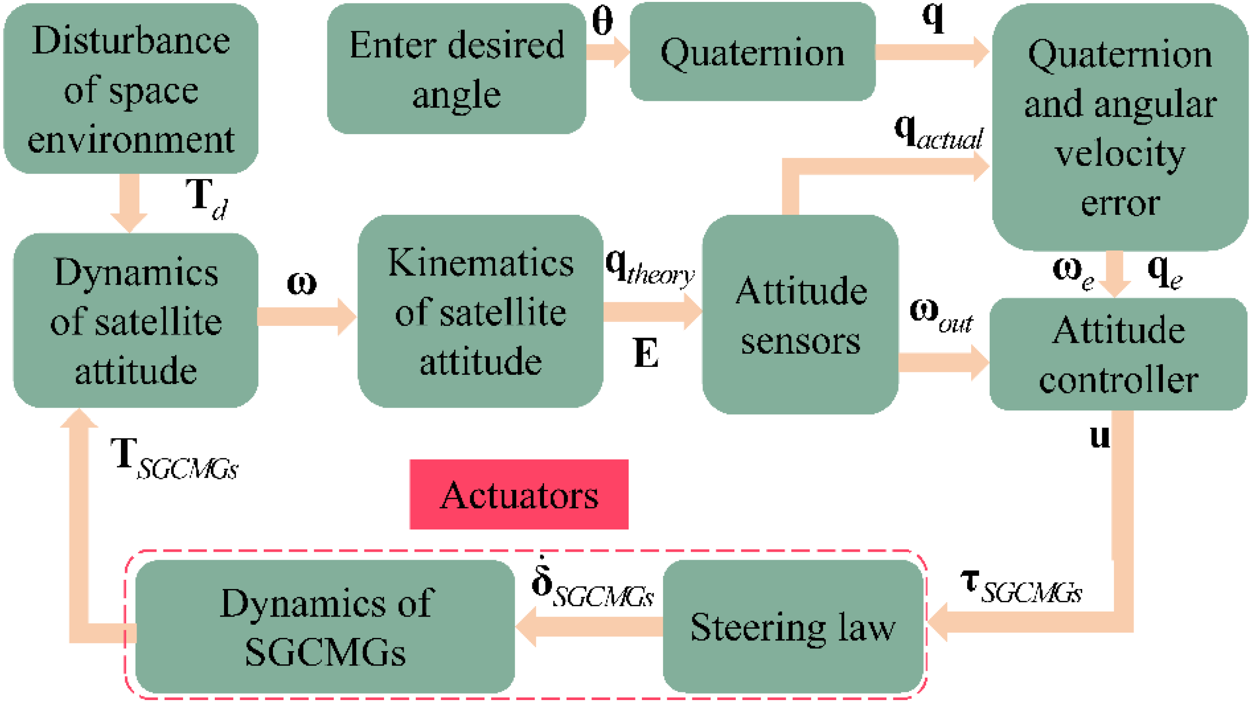
A detailed modeling of the hyper-agile satellite ACS is established.
(b)
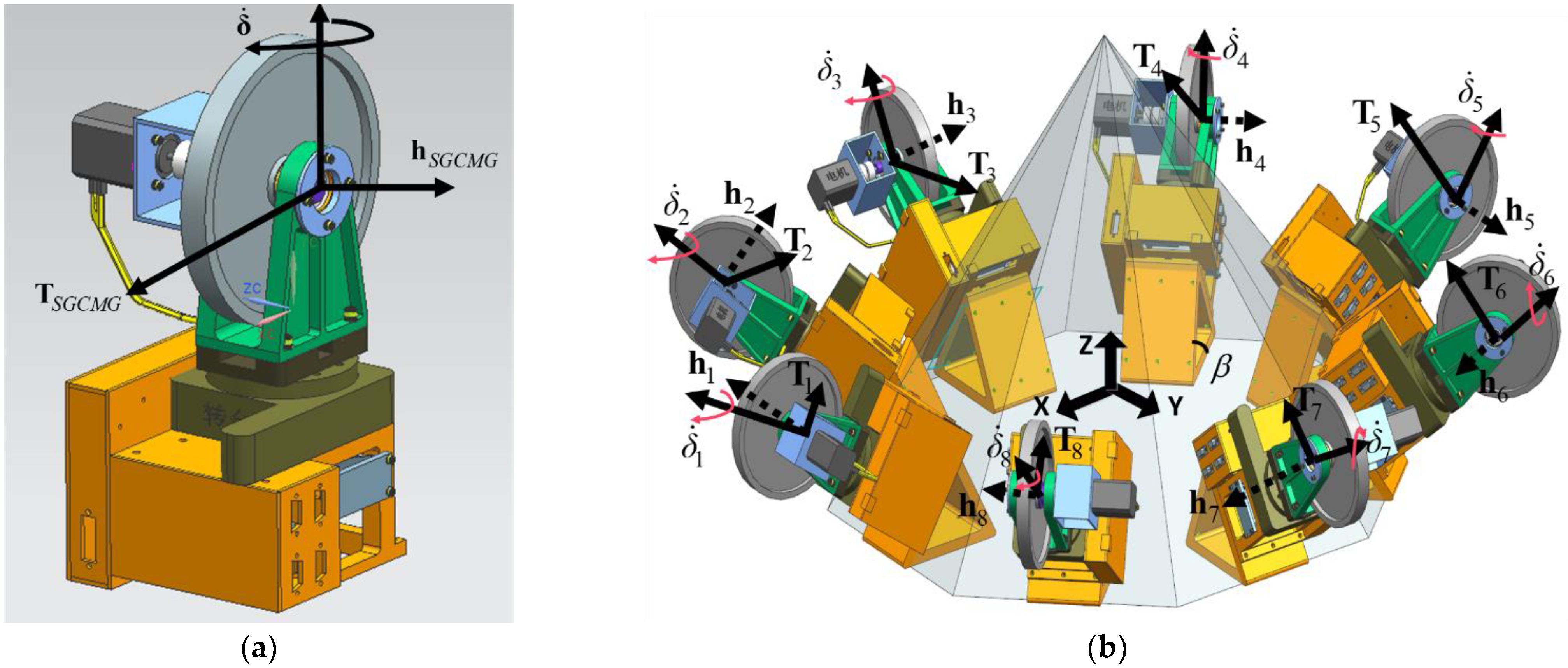
An octagonal cone-type SGCMGs is designed as an actuator, and the momentum characteristics are analyzed in detail. Based on this design, norm L and norm L 2 are introduced to define evaluation metrics for SGCMGs to analyze the configuration benefits, respectively.
(c)
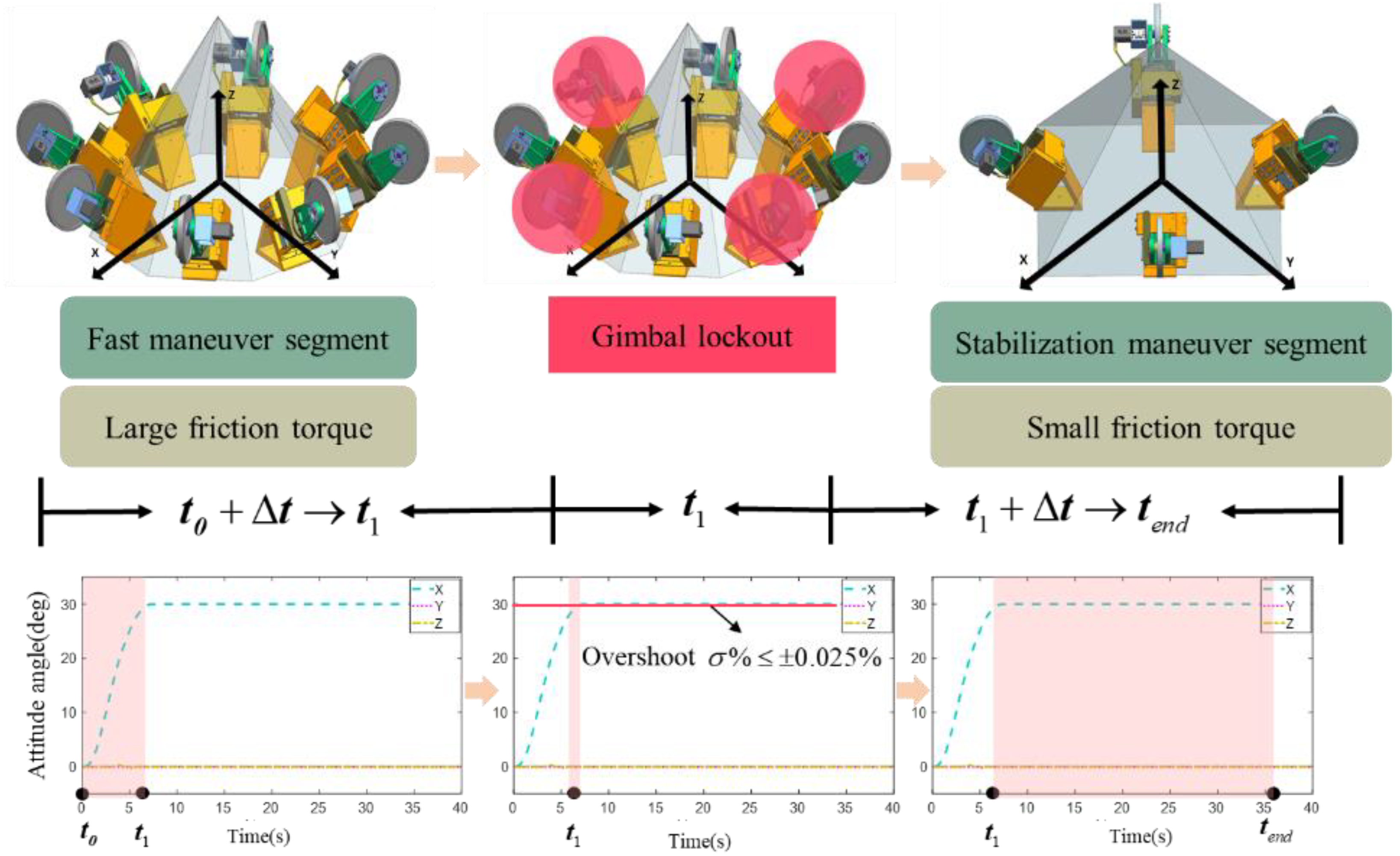
The disturbance mechanism of SGCMGs is analyzed, and the disturbance torque is fitted by experimental data to be applied to the later ACS disturbance model. According to the real flying results of the Jilin-1 hyper-agile satellite, two practical engineering problems are faced. In the first place, unknown frictional disturbances of the low-cost miniaturized SGCMG are difficult to eliminate. In the second place, it is difficult to balance the trade-off between ultra-fast maneuverability and high stability during the attitude maneuver. The concept of reconfigurable SGCMGs is proposed to address the above problems: by switching between octagonal cone-type SGCMGs and pyramid-type SGCMGs to allocate the torque that meets the attitude control requirements of different maneuver segments.
(d)
The overall design of the hyper-agile satellite ACS is completed that includes the modeling of the steering law and controller. The simulations demonstrate the feasibility and superiority of the reconfigurable octagonal cone-type SGCMGs system.

2. Mathematical Model

We first model the in-orbit environment disturbance, and the ACS of hyper-agile satellite is shown in Figure 1.

2.1. Kinematics

The attitude representations using Euler angle description and quaternion description are given, respectively, in Ref. [1].

2.1.1. Kinematic Characterization of Euler Angle

After giving the transformation matrix between coordinate systems (see Appendix A), the kinematic equation described by Euler angle is obtained as [1,39]
φ ˙ θ ˙ ψ ˙ = A 1 ω = ( ω x cos ψ ω y sin ψ ) / c θ ω x sin ψ + ω y cos ψ ( ω y sin ψ sin θ ω x cos ψ sin θ ) / cos θ + ω z .
where ω = ω x ω y ω z Τ , A = c ψ c θ s ψ 0 s ψ c θ c ψ 0 s θ 0 1 (calculated in x y z rotation order).

2.1.2. Kinematic Characterization of Quaternion

Setting a reference orbital coordinate system, the kinematic transformation relationship between the body and orbital coordinate systems expressed by quaternions is [1]
q ˙ = 1 2 T q ω q ˙ 0 = 1 2 q Τ ω ,
where q is the vector part of the quaternion, q = q 1 q 2 q 3 Τ , and T ( q ) = q 0 q 3 q 2 q 3 q 0 q 1 q 2 q 1 q 0 .
Matrix form of motion described by quaternions is [1]
q ˙ 0 q ˙ 1 q ˙ 2 q ˙ 3 = 1 2 q 0 q 1 q 2 q 3 q 1 q 0 q 3 q 2 q 2 q 3 q 0 q 1 q 3 q 2 q 1 q 0 0 ω x ω y ω z .

2.2. Dynamics of Hyper-Agile Satellite Attitude

Then, the dynamics of hyper-agile satellite attitude can be written as
J ω ˙ = ω × J ω + T S G C M G + T d ,
where J is the moment of inertia of hyper-agile satellite, T S G C M G is the output torque of SGCMGs, and T d is the environment disturbance torque.

2.3. Environment Disturbance Torques

2.3.1. Gravity Gradient Torque

The component of the gravitational gradient torque [40,41] in the satellite body coordinate system is
T g x = 3 ω 0 2 [ ( J y J z ) φ + J y z J x y θ ] T g y = 3 ω 0 2 [ ( J x J z ) θ J x z J x y φ ] T g z = 3 ω 0 2 [ J y z θ + J x z φ ]
where T g x , T g y , T g z are the three-axis torque of gravitational gradients, J = [ J x , J y , J z ] Τ is the moment of inertia, J x y , J x z , J y z are the moments of inertia between each axis, and T g = [ T g x   T g y   T g z ] Τ .

2.3.2. Aerodynamic Torque

The model of aerodynamic torque T a for the satellite is [41]
T a = ρ S × F S F S = 1 2 C d ρ S V S 2 V S = ω o ω e × r S
where F S is aerodynamic drag force, ρ S is the position vector of the center of pressure with respect to the center of mass of the satellite, ρ is atmospheric density, V S is velocity of the satellite relative to the atmosphere, C d is drag coefficient, S is characteristic area of windward, and r S is the geocentric radius of the area S .

2.3.3. Sunlight Pressure Torque

The model of sunlight pressure torque T p for satellite is [42]
T p = M r × F p F p = ς c [ ( 1 + R ) + 2 3 ν ] O ,
where F p is the force of the sunlight pressure, M r is force arm of sunlight pressure, ς is solar constant, c is speed of light, O is sunlight pressure area, R is reflectivity of the surface, and ν is transmissibility of the surface.

2.3.4. Magnetic Torque

The magnetic torque model on the satellite due to the Earth is [43]
T m = T m x T m y T m z = M b × B b = M y b B z b M z b B y b M z b B x b M x b B z b M x b B y b M y b B x b ,
where M b = [ M x b M y b M z b ] Τ is remanent magnetic moment of the satellite and B b = [ B x b B y b B z b ] Τ is magnetic field density of satellite position.
In summary, the environment disturbance torques T d are expressed as
T d = T g + T a + T p + T m .

2.4. Attitude Sensors

2.4.1. Stellar Sensor Model

A stellar sensor model can be built as [44,45]
q actual = q nominal q noise ,
where q actual is the actual stellar sensor measurement, q nominal is the theoretical attitude quaternion, and q noise is the stellar sensor noise quaternion.
If there is only a small angle change, the relationship between the quaternion and the Euler angle is satisfied as
φ θ ψ 2 q 1 q 2 q 3 .
Then, given the accuracy index [ σ x   σ y   σ z ] in Euler angle form, the noise quaternion is expressed as
q noise = 1 2 N ( 0 , σ x 2 )   1 2 N ( 0 , σ y 2 )   1 2 N ( 0 , σ z 2 )   1 q Τ q .

2.4.2. Fiber Optic Gyro Model

Without considering the scale factor and installation error, the model of the fiber optic gyro in period t 0 , t 0 + Δ t is [1]
ω o u t t 0 + Δ t = ω t 0 + Δ t + 1 2 c t 0 + Δ t + c t 0 + 1 12 σ ARW 2 Δ t + σ ARRW 2 Δ t 1 / 2 N A ( 0 , 1 ) c t 0 + Δ t = c t 0 + σ ARW Δ t 1 / 2 N R ( 0 , 1 ) ,
where ω o u t is output value of the gyro, ω is the angular velocity of the satellite, c is constant drift of gyro, N A and N R are the uncorrelated zero-mean white noise, σ ARW and σ ARRW are the angle random walk and angular rate random walk of the gyro, respectively.

3. Configuration Design and Benefit Analysis of SGCMGs

3.1. Problem Formulation

Attitude maneuverability and stability enhancement are the main design objectives of the hyper-agile satellite ACS, and the integrated momentum output capability of the actuator SGCMGs system needs to be considered in the configuration design.
First, to describe the momentum envelope of SGCMGs without failure units, the output momentum of n units of SGCMGs is defined as h = [ h 1     h i     h n ] Τ and h 1 =   h i = = h n .
Second, to depict the SGCMGs momentum envelope with m failed units, we define the existence of h i = 0 in h .
Finally, to characterize the SGCMGs singular momentum envelope, the singular momentum of n units of SGCMGs is defined as h ^ i s = i = 1 n h i s ( i ) = i = 1 n ε i g i × u × g i g i × u and the singularity momentum combination matrix ε i = ± 1 in ε = [ ε 1     ε i   ε n   ] .
It is difficult to completely analyze the momentum envelope of the configurations using the above no failure unit, m failed units, and singularity description of the momentum output capabilities of SGCMGs. In this chapter, the configuration evaluation method is proposed and analyzed in detail for the proposed configuration of SGCMGs.

3.2. Dynamics of 8-SGCMGs

We design a positive octagonal cone-type SGCMGs (named 8-SGCMGs) as an actuator for the hyper-agile satellite, which consists of 8 units of SGCMGs. A unit of SGCMGs mainly consists of flywheel and turntable gimbal, and the working principle is to change the flywheel momentum direction by driving the gimbal rotation through a servo turntable. SGCMG can output the torque exponentially with its gimbal angular velocity [20,21,22]. The composition schematic of SGCMG and 8-SGCMGs are illustrated in Figure 2.
The gimbal axis of SGCMG is always perpendicular to the flywheel axis, and when the gimbal axis rotates, the direction of momentum changes and the output torque of the entire SGCMG system can be obtained from the coupling calculation between the momentum and the velocity of the gimbal axis. The gimbal angular velocity of SGCMGs is defined as δ ˙ , and the momentum generated by flywheel is defined as h S G C M G . The output torque of the SGCMG is given as
T S G C M G = δ ˙ × h S G C M G .
According to the momentum exchange principle, the configuration of distributed SGCMGs is required to realize the fast maneuver of hyper-agile satellite attitude, and the mathematical model of the momentum H of the distributed SGCMGs is
H = h S G C M G ( A sin δ + B cos δ ) E .
where A and B are the installation matrices of gimbal angle, and E = 1 1 1 Τ is the unit vector.
Here, A and B are in the form of
A = a 11 a 1 n a 21 a 2 n a 31 a 3 n , B = b 11 b 1 n b 21 b 2 n b 31 b 3 n .
sin δ and cos δ are
sin δ = sin δ 1 0 0 sin δ n ,   cos δ = cos δ 1 0 0 cos δ n .
The total torque T S G C M G s generated by SGCMGs in the body coordinate system of a satellite is
T S G C M G s = H ˙ = J S G C M G s ( δ ) δ ˙ h ,
where J S G C M G s ( δ ) = A cos δ B sin δ is the Jacobi matrix of the gimbal and δ ˙ = δ ˙ 1 δ ˙ 2 δ ˙ n Τ is the angular velocity matrix of the gimbal of SGCMGs.
Then, the momentum of 8-SGCMGs is defined as H 8-SGCMGs , and we get
H 8-SGCMGs = H x H y H z = h 0 c β s δ 1 + c β c 45 ° s δ 2 s 45 ° c δ 2 + c β c 135 ° s δ 4 c δ 3 s 135 ° c δ 4 c β s δ 5 + c β c 225 ° s δ 6 s 135 ° c δ 6 + c δ 7 + c β c 315 ° s δ 8 s 135 ° c δ 8 c δ 1 + c β s 45 ° s δ 2 + c 45 ° c δ 2 + c β s δ 3 + c β s 135 ° s δ 4 + c 135 ° c δ 4 c β s δ 5 + c β s 225 ° s δ 6 + c 225 ° c δ 6 c β s δ 7 + c β s 315 ° s δ 8 + c 315 ° c δ 8 s β s δ 1 + s β s δ 2 + s β s δ 3 + s β s δ 4 + s β s δ 5 + s β s δ 6 + s β s δ 7 + s β s δ 8 .
.
The gimbal axes of 8-SGCMGs are perpendicular to the side and the inclination β . To approximate the momentum body as a sphere, let H x = H y = H z obtain β = arccos ( 3 / 3 ) 54.73 ° .

3.3. Benefit Analysis of 8-SGCMGs

To demonstrate the advantages of the proposed 8-SGCMGs configuration, we analyze the characteristics of the momentum envelope, failure momentum envelope, and singular momentum envelope, respectively. Based on these characteristics, the momentum efficiency (ME), failure momentum efficiency (FME), and singular momentum efficiency (SME) are defined to evaluate the configurations comprehensively.

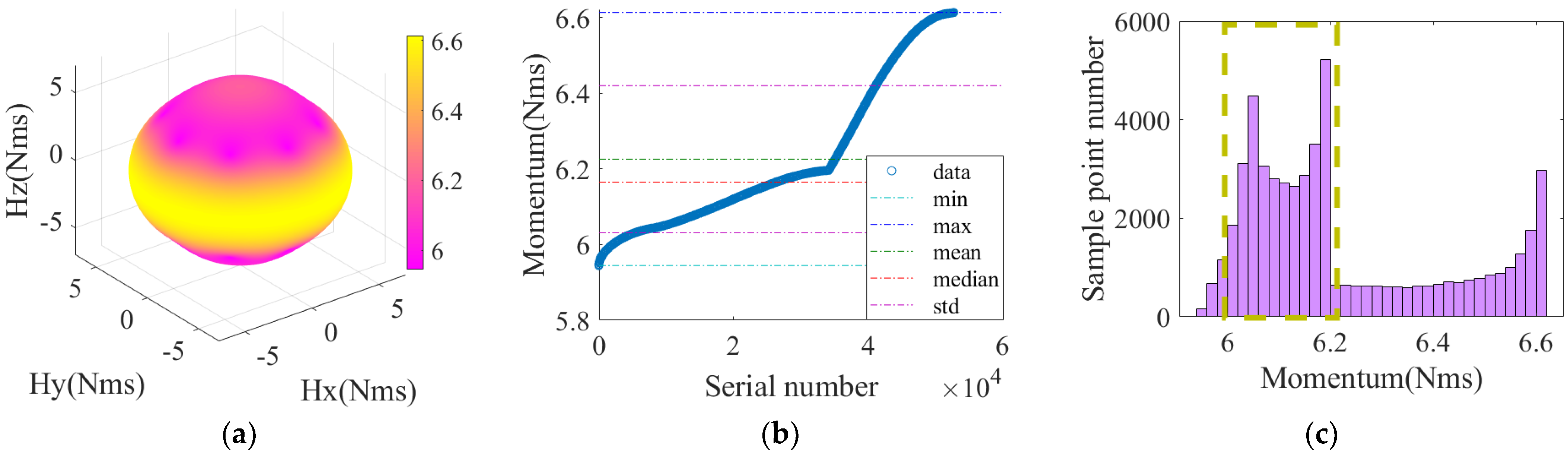
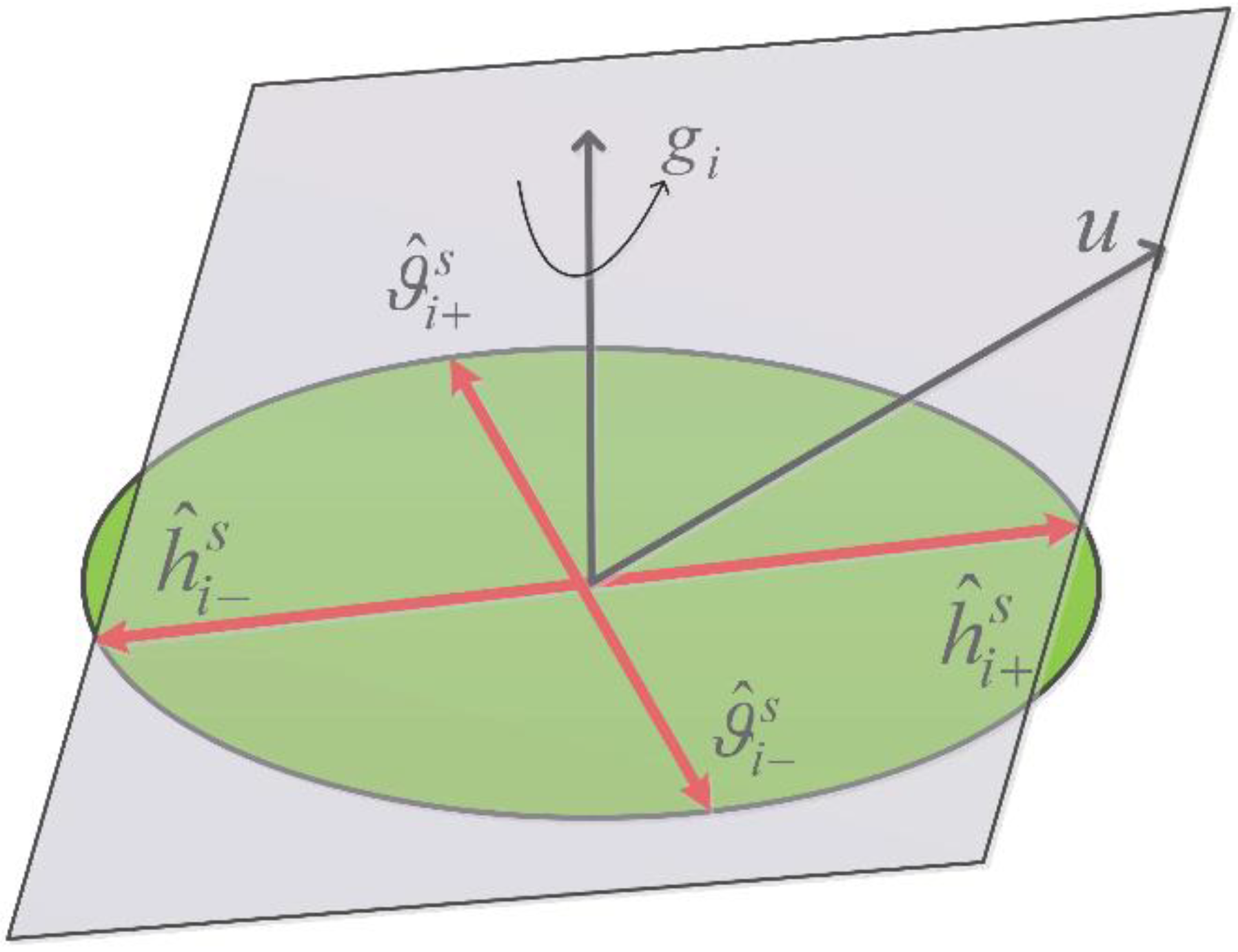
3.3.1. Momentum Envelope

To visualize the momentum envelope, we set 53,000 momentum envelope sample points S i ( i = 1 , 2 , 3 e n d ) = i to count the momentum sample values Z = Z 1 , Z 2 Z i Z e n d . The statistical parameters include value interval [ Z min , Z max ] , mean Z mean , median Z median , and standard deviation σ Z . The momentum of SGCMG is given to h 0 = 1 Nms , and the momentum characteristic is shown in Figure 3.
Figure 3a shows that the momentum envelope of 8-SGCMGs has fine linearity and symmetry, which facilitates the smooth torque output of the actuator and greatly reduces the design difficulty of the steering law. Figure 3b,c show the momentum synthesis capacity and concentration, which reflects the high maneuverability of 8-SGCMGs. The statistics are shown in row 2 of Table 1.

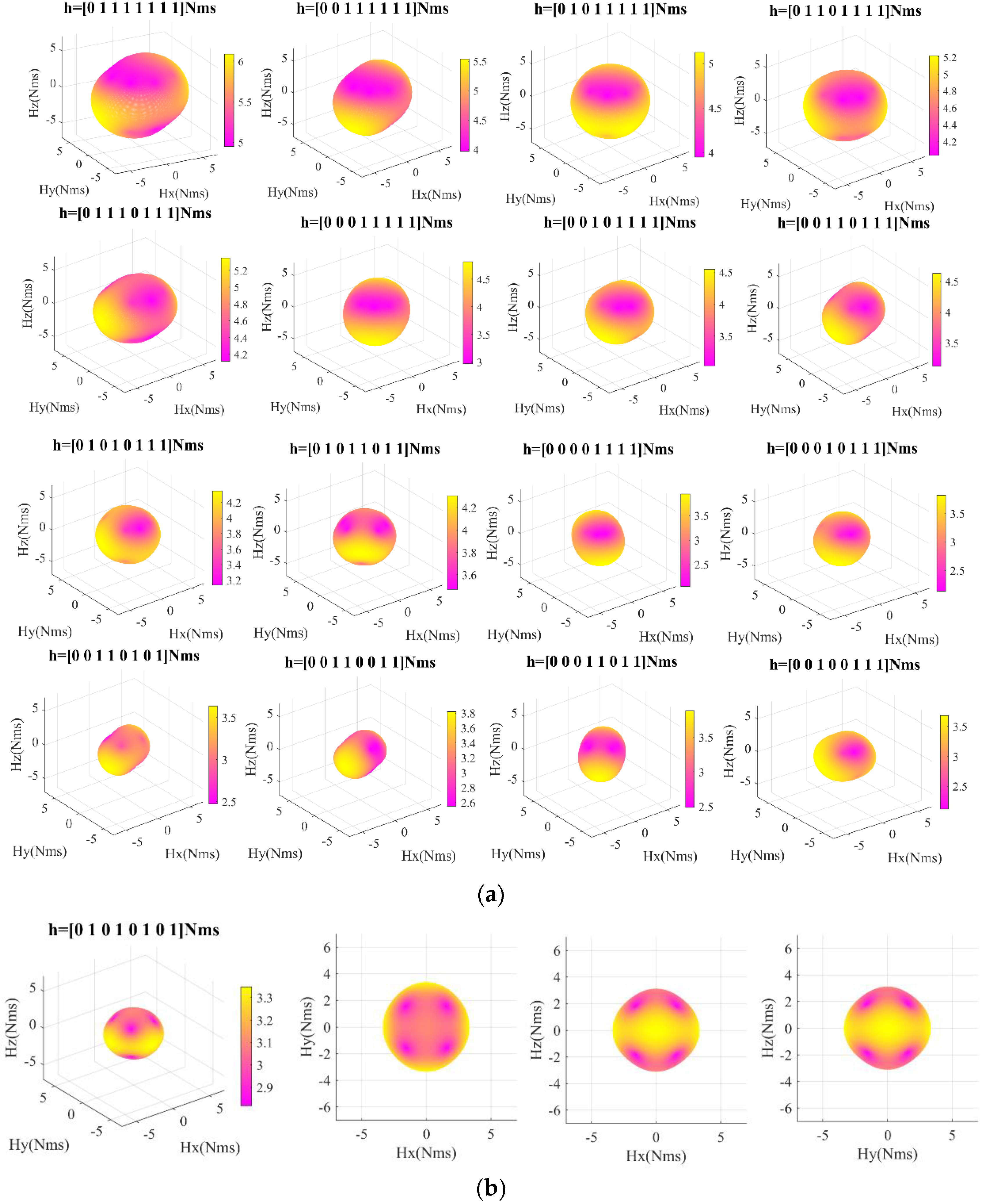
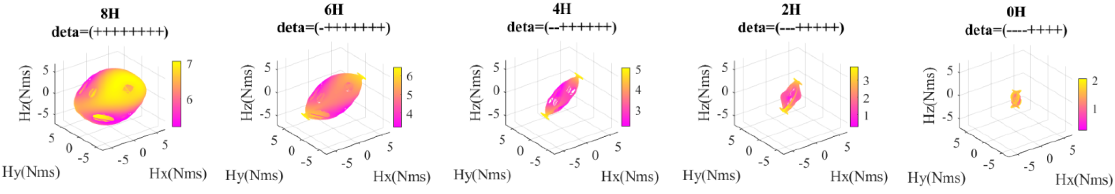
3.3.2. Failure Momentum Envelopes

The SGCMGs with fewer than 4 units are an underactuated system. If there are fewer than 4 units of SGCMGs, then the system is not reconfigurable. h 0 = 0 is defined as a particular SGCMG failure, and there are 17 failure momentum combinations of 8-SGCMGs. Similarly, taking h 0 = 1   Nms , the 17 failure momentum envelopes are visualized as shown in Figure 4, and statistics are shown in Table 1.
The momentum envelope decays (seen in Figure 4) as the number of failure units of SGCMGs increases. By considering the reconfigured configuration with 4 symmetric failure units, the configuration still maintains fine linearity and symmetry. Table 1 shows that its standard deviation value is small and the minimum momentum value is the largest, which indicates its high concentration of momentum output and strong momentum output capability.

3.3.3. Singular Momentum Envelopes

The output momentum h i ( i ) of the SGCMGs unit acts together with the gimbal angular velocity δ ˙ to obtain the output torque T S G C M G s , which is used to provide input of the controller. T S G C M G s is in the space of value fields expressed by the column vectors of Jacobi matrix J S G C M G s , and the column vectors ϑ ^ 1 , ϑ ^ 2 , , ϑ ^ i of Jacobi matrix J S G C M G s are position functions of the gimbal angles. The above calculation rules satisfy
T S G C M G s = d h i d t = d h i ( 1 ) d t d h i ( 2 ) d t d h i ( i ) d t = ϑ 1 + ϑ 2 + + ϑ i   = ( δ ˙ 1 × h i ( 1 ) + δ ˙ 2 × h i ( 2 ) + + δ ˙ i × h i ( i ) ) = ( δ ˙ 1 h i ( 1 ) ϑ ^ 1 + δ ˙ 2 h i ( 2 ) ϑ ^ 2 + + δ ˙ i h i ( i ) ϑ ^ i )   = h 0 ϑ ^ 1 ϑ ^ 2 ϑ ^ i δ ˙ 1 δ ˙ 2 δ ˙ i = h 0 J S G C M G s δ ˙ ,
where J S G C M G s = ϑ ^ 1 ϑ ^ 2 ϑ ^ i , δ ˙ = δ ˙ 1 δ ˙ 2 δ ˙ i T and h i   ( i = 1 , 2 , , n ) is the output momentum of the SGCMGs unit.
A particular combination of gimbal angles makes the column vectors ϑ ^ 1 , ϑ ^ 2 , , ϑ ^ i co-linear, at which point the Jacobi matrix J S G C M G s appears to degrade in rank. To this end, the actuator falls into a singular state, which can be expressed as rank ( J S G C M G s ) < 3 . The result indicates that the SGCMGs system can only output torque in a certain plane and cannot complete three-axis attitude control, and the singularity schematic diagram of the SGCMGs is shown in Figure 5.
To visualize the singular momentum envelopes, ε = ε 1 ε 2 ε n is introduced. The two equations ε i = ± 1 with different singularities are combined into h ^ i s , and there are 2 n combinations of values. However, ε is all positive and all negative corresponding to the same singular surface, so ε has a total of 2 n 1 combinations of values. Plotting the singular envelope by traversing the vector u through the entire unit sphere space, the singular momentum can be further expressed as
ϑ ^ i u = 0 , ( i = 1 , 2 , 3 ..... , n ) h ^ i s = i = 1 n h i s ( i ) = i = 1 n ε i g i × u × g i g i × u ,
The 8-SGCMGs have 128 combinations of ε values. The singular planes of 8-SGCMGs are classified into external saturated 8H singular planes, internal 6H singular planes, internal 4H singular planes, internal 2H singular planes, and 0H singular planes based on the characteristics of different singularities. The singular momentum envelopes are shown in Figure 6 and the statistics are shown in Table 2.
In summary, the momentum, failure momentum, and singular momentum envelopes of the 8-SGCMGs are analyzed in detail. Based on the norm L and norm L 2 , we define ME, FME, and SME, respectively.
Definition 1.
(ME) The ratio γ L of the value of the momentum envelope calculated by the norm L to the algebraic sum of the momentum of the system, described as γ L = h / n h 0 , where γ L [ 0 , 1 ] , h is norm L of momentum envelope, n is the number of SGCMGs units, and h is value of the momentum envelope.
The ratio γ L 2 of the value of the momentum envelope calculated by the norm L 2 to the algebraic sum of the momentum of the system, described as γ L 2 = h 2 / 𝓁 n 2 h 0 2 , where h 2 is norm L 2 of momentum envelope, and 𝓁 is number of sample points.
Remark 1.
The momentum efficiency reflects the form of the distribution of the system momentum in space. The higher the ratio γ L and γ L 2 , the higher the momentum output capacity of the configuration.
Definition 2.
(FME) The ratio λ L of the failure momentum envelope of the norm L solution to the algebraic sum of the system momentum is summed in proportion to the different failure combinations. The ratio λ L is described as λ L = i = 1 m j = 1 k h i j / ( n 1 ) h 0 k ( n i ) , where λ L [ 0 , 1 ] , m is number of failure units of SGCMGs, k is number of different failure combinations, and h i j is norm L of j t h combination of i failure units.
The ratio λ L 2 of the failure momentum envelope of the norm L 2 solution to the algebraic sum of the system momentum is summed in proportion to the different failure combinations. The ratio λ L 2 is described as λ L 2 = i = 1 m j = 1 k n h i j 2 / 𝓁 n 2 h 0 2 ( n 1 ) ( n i ) k , where λ L 2 [ 0 , 1 ] , h i j 2 is norm L 2 of j t h combination of i failure unit, and 𝓁 is the number of sample points.
Remark 2.
Failure momentum efficiency reflects the ability of the reconstructed system to generate momentum after the failure of different unit combinations. The larger the ratio λ L and λ L 2 , the higher the failure momentum efficiency.
Definition 3.
(SME) The ratio χ L of the singular momentum envelope of the norm L solution to the algebraic sum of the system momentum is summed in proportion to the different singular combinations. The ratio χ L is described as χ L = α = 1 m h α / m , where χ L [ 0 , 1 ] and m is the classification number of the singular momentum envelope.
The ratio χ L 2 of the singular momentum envelope of the norm L 2 solution to the algebraic sum of the system momentum is summed in proportion to the different singular combinations. The ratio χ L 2 is described as χ L 2 = α = 1 m h α 2 / m 𝓁 n 2 h 0 2 , where χ L 2 [ 0 , 1 ] , and 𝓁 is the number of sample points.
Remark 3.
Singular momentum efficiency reflects the ability of the system to generate momentum at different singular combinations. The larger the ratio of χ L and χ L 2 , the higher the singular momentum efficiency.
Typical SGCMGs configurations are divided into 4 units, 5 units, and 6 units of SGCMGs; the expression for the installation of the gimbal is given as H 4-SGCMGs , H 5-SGCMGs , and H 6-SGCMGs .
H 4-SGCMGs = h 0 c β s δ 1 c δ 2 + c β s δ 3 + c δ 4 c δ 1 c β s δ 2 c δ 3 + c β s δ 4 s β s δ 1 + s β s δ 2 + s β s δ 3 + s β s δ 4 , β = 53.1 ° .
H 5-SGCMGs = h 0 c β c δ 1 + c β c 72 ° c δ 2 s 72 ° s δ 2 c β c 54 ° c δ 3 c 54 ° s δ 3 c β c 36 ° c δ 4 + c β c 36 ° c δ 4 + s 36 ° s δ 4 c β + c β s 18 ° c δ 5 + c β s δ 5 s δ 1 + c β s 72 ° c δ 2 + c 72 ° s δ 2 + c β c 54 ° c δ 3 s 54 ° s δ 3   c β s 36 ° c δ 4 c 36 ° s δ 4 c β c 18 ° c δ 5 + s 18 ° s δ 5 s β s δ 1 + s β s δ 2 + s β s δ 3 + s β s δ 4 + s β s δ 5 , β = 60.42 .
H 6-SGCMGs = h 0 c β s δ 1 + c β c 60 s δ 2 s 60 c δ 2 + c β c 120 s δ 3 s 120 c δ 3 + c β c 240 s δ 5 s 240 c δ 5 + c β c 300 s δ 6 s 300 c δ 6   c δ 1 + c β s 60 s δ 2 + c 60 c δ 2 + c β s 120 s δ 3 + c 120 c δ 3 c δ 4 + c β s 240 s δ 5 + c 240 c δ 5 + c β s 300 s δ 6 + c 300 c δ 6   s β s δ 1 + s β s δ 2 + s β s δ 3 + s β s δ 4 + s β s δ 5 + s β s δ 6 , β = 70.53 .
The results of the combined ME, FME, and SME metrics were used to define the evaluation metrics ν L and ν L 2 for SGCMGs based on norm L and norm L 2 as
ν L = γ L + λ L + χ L ν L 2 = γ L 2 + λ L 2 + χ L 2 .
Above metrics defined by norm L and norm L 2 focus on representing the maximum and overall benefits of the SGCMGs configuration, respectively. Typical configuration performance parameters are given in Table 3.
The results in Table 3 show that 5-SGCMGs have the best maximum benefit, while 8-SGCMGs have the best overall benefit, and the conclusion that 8-SGCMGs configuration is the optimal configuration is proposed for the first time in the literature.

4. Reconfigurable SGCMGs System Design

4.1. Problem Formulation

In the hyper-agile satellite configuration, the low-cost miniaturized SGCMGs face an intractable challenge of unknown frictional disturbance, making it difficult to balance the trade-off between high maneuverability and stability during attitude maneuver.
When all units of SGCMGs are steered cooperatively in accordance with the desired gimbal angular velocity θ ˙ f , there is the disturbance torque limit T b in T S G C M G . The relationship between θ ˙ f and T b of unit of SGCMGs cannot be determined quantitatively directly. According to Equation (4), it is known that the attitude angular velocity error (stability) is influenced by T b in T S G C M G . In this chapter, T b is calculated by model analysis and disturbance measurement experiments, and the reconfigurable SGCMGs system design method is proposed to fundamentally improve the attitude stability.

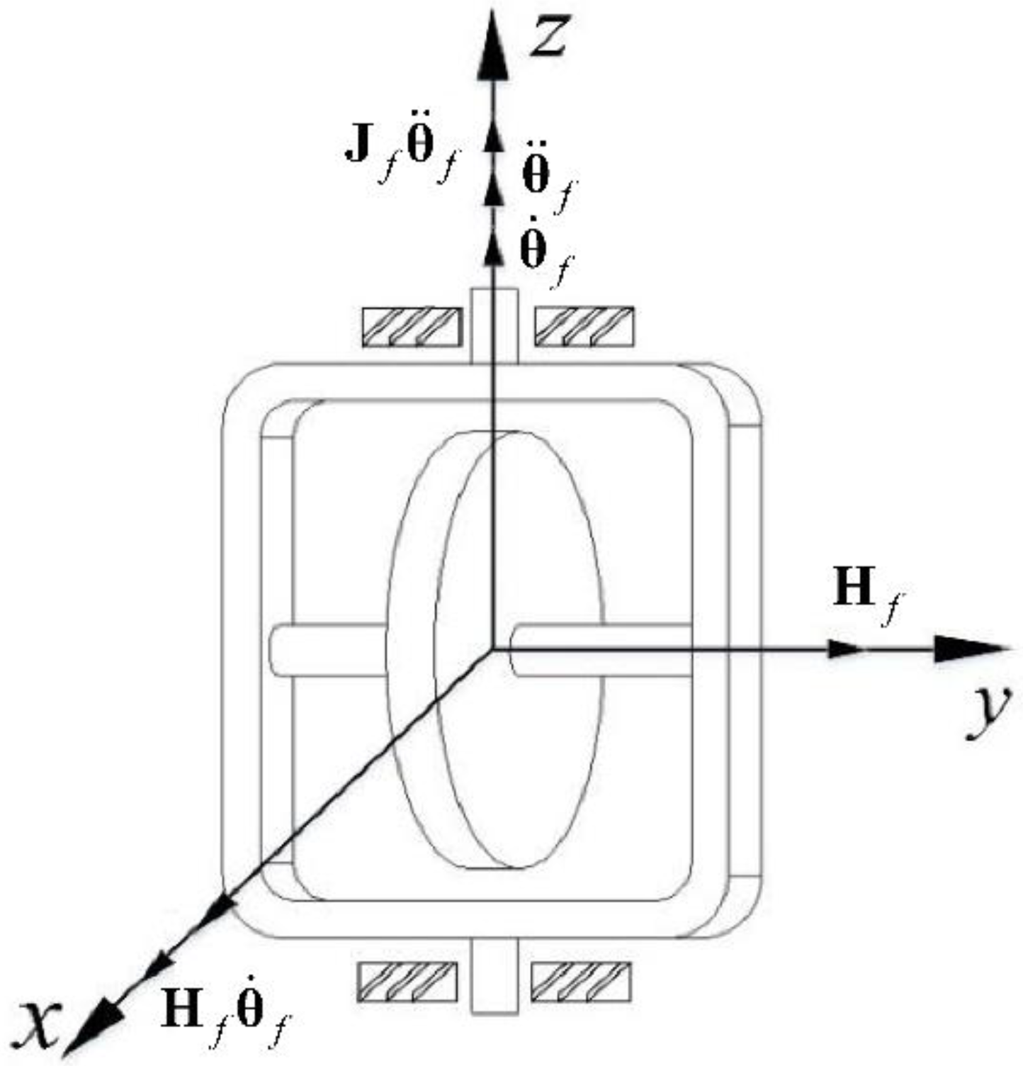
4.2. Disturbance Torque Analysis of 8-SGCMGs

When the gimbal servo system of SGCMG performs a high dynamic response, the momentum of flywheel direction is forced to change, which in turn generates the flywheel bearing radial load friction torque and other unknown disturbance torque. This will eventually affect the stability of flywheel and output torque accuracy of SGCMG, and the schematic diagram of the SGCMG system is shown in Figure 7.
The torque balance equation of the flywheel is first given as
M = M I + M G M I = J r θ ¨ f M G = H f θ ˙ f H f = J z ω r ,
where M is the external torque of the flywheel, J r is the equatorial rotational inertia of the flywheel, M I is the torque of inertia, J z is the rotational inertia of pole, M G is the gyroscopic torque, θ ¨ f is the angular acceleration of gimbal, H f is the momentum of the flywheel, θ ˙ f is the angular velocity of the gimbal, and ω r is the angular velocity of the flywheel [11,12].
Neglecting the effect of gimbal angular acceleration in Equation (27), the equation for the frictional disturbance torque of the gimbal speed bearing radial load is as follows.
T b = α F b d F b = M l = H f θ ˙ f l ,
where α is the friction factor, d is the radius of the inner ring of the bearing, F b is the force generated by the rotation of the flywheel, and l is the distance from the center of the bearing to the center of mass of the flywheel.
The relationship between the angular velocity of the gimbal and the disturbance torque can be obtained as
T b = α H f θ ˙ f d l .
The friction factor α in the above equation is difficult to measure directly, so the relationship between gimbal angular velocity θ ˙ f and disturbance torque T b of unit of SGCMGs cannot be determined quantitatively directly. We indirectly measured the data of θ ˙ f and T b through experiments and fitted the two to approximate the relationship; the experimental setup is shown in Figure 8, where the steady speed experiment of a unit of SGCMGs is illustrated in left figure and the preliminary experiment of air floatation table with 8-SGCMGs is illustrated in the right figure. Main parameters of the SGCMG prototype are shown in Table 4.
To ensure the accuracy of the experimental data, the gimbal angular velocity and flywheel disturbance torque parameters are repeatedly sampled under the same output torque command, and 10 sets of data are taken as the average values shown in Table 5.
According to the analysis of the experimental data, when | θ ˙ f | < 0.037 , T b remains near ± 0.005 Nm ; when | θ ˙ f | 0.037 , T b is larger, Equation (29) is obtained by multiple spline curve fitting in MATLAB.
T b = 0.005 ,     | θ ˙ f | < 0.037 1.099 | θ ˙ f | 5 2.504 | θ ˙ f | 4 + 2.155 | θ ˙ f | 3 0.8627 | θ ˙ f | 2 + 0.1695 | θ ˙ f | 0.0001014 ,   | θ ˙ f | 0.037 .
To sum up, the first contribution of this section is to propose the flywheel frictional disturbance model, which reveals that both the friction factor and the disturbance torque increase with the increase in flywheel momentum. The second contribution is that the proposed disturbance model can be used as a simulation input for the hyper-agile satellite ACS, and the model presents that this configuration can only reach ± 0.005   Nm in torque output accuracy, and there are unknown disturbances that cannot be resolved to affect the system stability.

4.3. Reconfiguration of 8-SGCMGs into 4-SGCMGs

The rotation of each gimbal angle in the 8-SGCMGs generates more frictional disturbance torque, which can meet the needs of large-angle fast maneuvers of hyper-agile satellites, but it is difficult to guarantee its stability at the end of the maneuver. The four symmetrical failure units’ reconfiguration of 8-SGCMGs has been analyzed in the previous section still maintains good linearity and symmetry (seen in Figure 4 and Table 1). The friction coefficient can be approximated to increase with increasing load momentum if the same maximum gimbal angular velocity is configured [11,12]. To achieve the same output torque, the overall size and mass of 4-SGCMGs are larger than 8-SGCMGs, and the output disturbance torque of both configurations is almost the same [46,47]. In the stabilization section, it is necessary to lock the gimbal angles of 4 symmetrical failure units of 8-SGCMGs and reconfigure them into 4-SGCMGs for the stabilization section maneuvers. The method can reduce about half of the disturbance torque at the physical level and achieve the goal of high stability.
The process of reconfiguring 8-SGCMGs into 4-SGCMGs can be divided into three stages (illustrated in Figure 9); the function of control and steering allocation is clearly given in Table 6. Firstly, in the fast attitude maneuver segment, the 8-SGCMGs provide large torque with more frictional disturbance torque when t 0 + Δ t t 1 . Secondly, the gimbal angle locking of 4-SGCMGs is reconfigured to 4-SGCMGs when the overshoot satisfies σ % ± 0.025 % . Finally, in the stabilization attitude maneuver segment, the 4-SGCMGs provide fine torque with smaller frictional disturbance torque.
The process of output torque change that switches from 8-SGCMGs to 4-SGCMGs can be described as
T S G C M G s = δ ˙ 8 ( t 0 + Δ t ) × h 8 + 8 T b , σ % > ± 0.025 % δ ˙ 4 ( t 1 ) × h 4 + 4 T b , σ % = ± 0.025 % δ ˙ 4 ( t 1 + Δ t ) × h 4 + 4 T b , σ % < ± 0.025 % .
Singular robust steering law with null motion is generally described as
δ ˙ = δ ˙ T + δ ˙ N = h 0 Q i # J S G C M G s T h 0 2 J S G C M G s Q i # J S G C M G s T + P # 1 τ S G C M G s + χ n P 1 = P # = 1 ε 3 ε 2 ε 3 1 ε 1 ε 2 ε 1 1 Q 8 1 = Q 8 # = Q 1 # . . . Q 2 # Q 3 # Q 4 # Q 5 # Q 6 # Q 7 # Q 8 # Q 4 1 = Q 4 # = Q 1 # 0 0 0 0 0 0 0 0 0 0 0 0 0 Q 3 # 0 0 0 0 0 0 0 0 0 0 0 0 0 Q 5 # 0 0 0 0 0 0 0 0 0 0 0 0 0 Q 7 # 0 0 0 0 0 0 0 0 0 = 0 exp μ det J S G C M G s J S G C M G s T ε i = ε 0 sin ω t + ϕ i ,
where δ ˙ T is the general form of steering law, δ ˙ N is the null motion of steering law, τ S G C M G s is the desired torque, χ is the factor of the null motion, n is the design form of the null motion, P and Q are positive definite symmetric matrices, respectively. According to Perturbation Theory [48], the singular escape strength parameter , the periodic perturbation parameter ε i , and the parameter to be set Q i # are derived.
Null motion is designed to
δ ˙ N = χ n n = I J S G C M G s Τ J S G C M G s J S G C M G s Τ 1 λ J S G C M G s d d = D ˙ = D Τ δ δ ˙ = D Τ δ δ ˙ T + D Τ δ δ ˙ N ,
where d is the gradient of the singular metric vector D ˙ with respect to the gimbal angular velocity δ . Some researchers [49,50,51] derive in detail the specific operation of d ; the elements in the J S G C M G s J S G C M G s Τ matrix are denoted by e i , j ( i , j = 1 , 2 , 3 ) ; λ is the singularity parameter.
Denoting the partial derivative with respect to δ k by e i , j , k ( i , j = 1 , 2 , 3 ; k = 1 , 2 n ) , the gradient component can be expressed as
D Τ δ = δ k e 11 e 12 e 13 e 21 e 22 e 23 e 31 e 32 e 33 = e 11 k e 12 k e 13 k e 21 e 22 e 23 e 31 e 32 e 33 + e 11 e 12 e 13 e 21 k e 22 k e 23 k e 31 e 32 e 33 + e 11 e 12 e 13 e 21 e 22 e 23 e 31 k e 32 k e 33 k .
Since the matrix J S G C M G s J S G C M G s Τ is a symmetric matrix, the above equation is given as
D Τ δ k = e 11 k e 22 e 23 e 23 2 + e 22 k e 11 e 33 e 13 2 + e 33 k e 11 e 22 e 12 2 + 2 e 12 k e 13 e 23 e 12 e 33 + 2 e 13 k e 12 e 23 e 22 e 13 + 2 e 23 k e 12 e 13 e 11 e 23 .
Singular robust steering law with null motion combines two capabilities: one is the singular avoidance capability of the steering law with null motion; another one is the singular escape capability of the singular robust steering law to keep the system away from singular states. The specific singular robust steering law with null motion is described as
δ ˙ = h 0 Q 8 # J S G C M G s Τ h 0 2 J S G C M G s Q 8 # J S G C M G s Τ + P # 1 τ S G C M G s     + χ I J S G C M G s Τ J S G C M G s J S G C M G s Τ 1 λ J S G C M G s d , σ % > ± 0.025 % h 0 Q 4 # J S G C M G s Τ h 0 2 J S G C M G s Q 4 # J S G C M G s Τ + P # 1 τ S G C M G s     + χ I J S G C M G s Τ J S G C M G s J S G C M G s Τ 1 λ J S G C M G s d , σ % > ± 0.025 % .

5. Simulation and Analysis

In this paper, we apply large-size 4-SGCMGs, 8-SGCMGs, and 8-SGCMGs reconfigured into 4-SGCMGs for maneuvering mode simulation. The quantitative statistics of the momentum envelopes of large 4-SGCMGs and 8-SGCMGs are comparable; then, the momentum of a unit of large 4-SGCMGs is approximately twice as large as that of a unit of 8-SGCMGs. The momentum of a unit of 8-SGCMGs is set to 7 Nms and that of a unit of large 4-SGCMGs is set to 14Nms, which can meet the actual engineering requirements. This section compared and analyzed the different configurations by providing the same control conditions. The controller uses the proportional-derivative (PD) control algorithm proposed previously [14,32] and described by Equation (36). The simulation parameters are listed in Table 7.
τ S G C M G s = J ω ˙ + ω × J ω J ( K p q e + K d ω e ) ,
where q e is the quadratic error, and ω e is the angular velocity error, K p is the proportional gain, and K d is derivative gain.
To demonstrate the effectiveness of the proposed actuator system and control scheme, extensive numerical simulations have been carried out. All the simulations are conducted in MATLAB/SIMULINK environment on an i7-8550U CPU/8 G 1.80 GHz machine. For practical consideration, we set the sampling frequency as 50 Hz. Assuming the same material and process in the simulation comparison, the disturbance torque magnitudes of large 4-SGCMGs and 8-SGCMGs are comparable according to Equation (29). These parameters of the disturbance simulation are listed in Table 8.
The simulations are carried out for different configurations of SGCMGs of hyper-agile satellite to visualize the attitude angle, attitude angular velocity, torque accuracy, and gimbal angular velocity, respectively. We set up two cases separately:
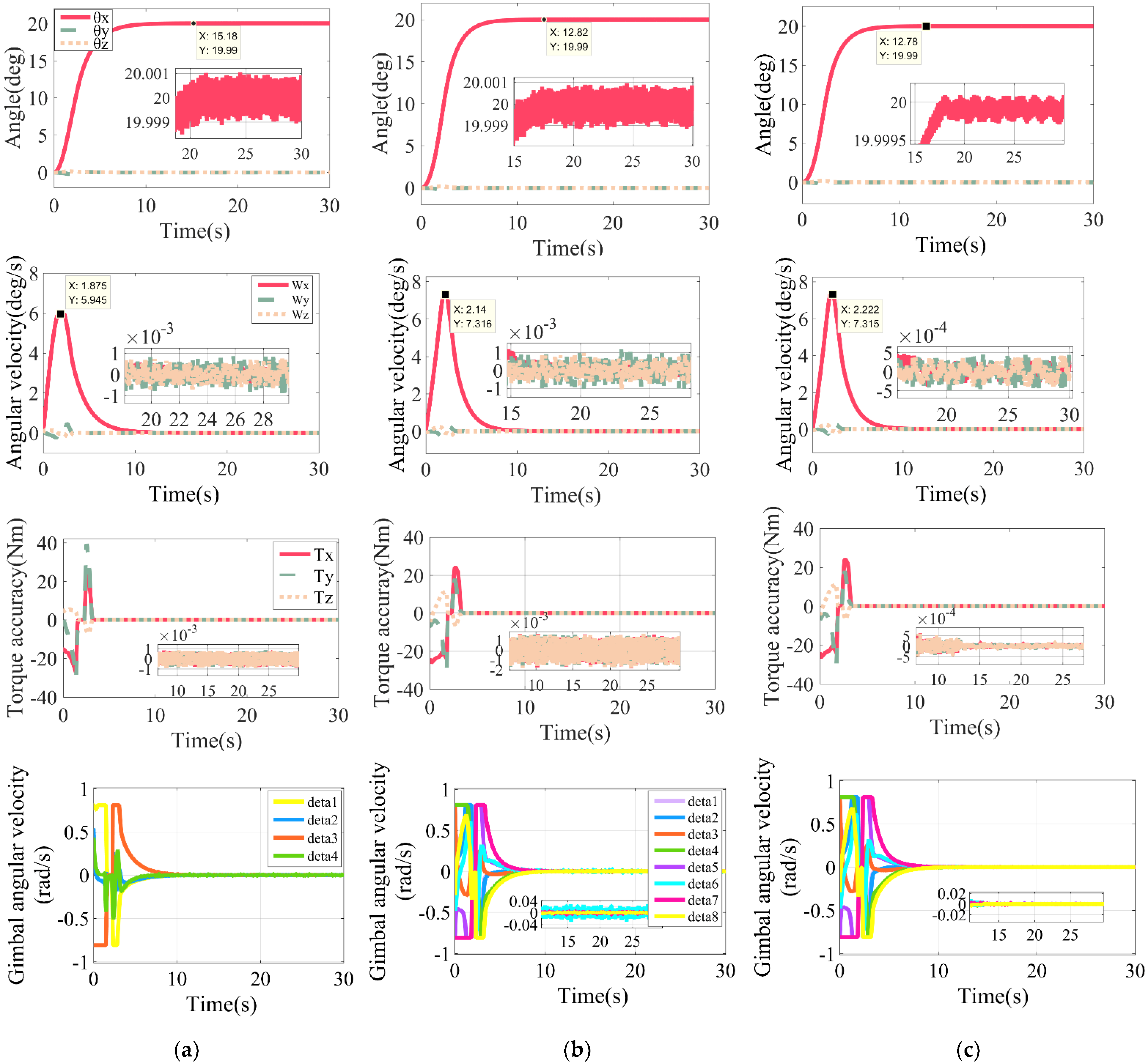
  • Case 1, a small angle of 20 deg around the x-axis attitude maneuver;
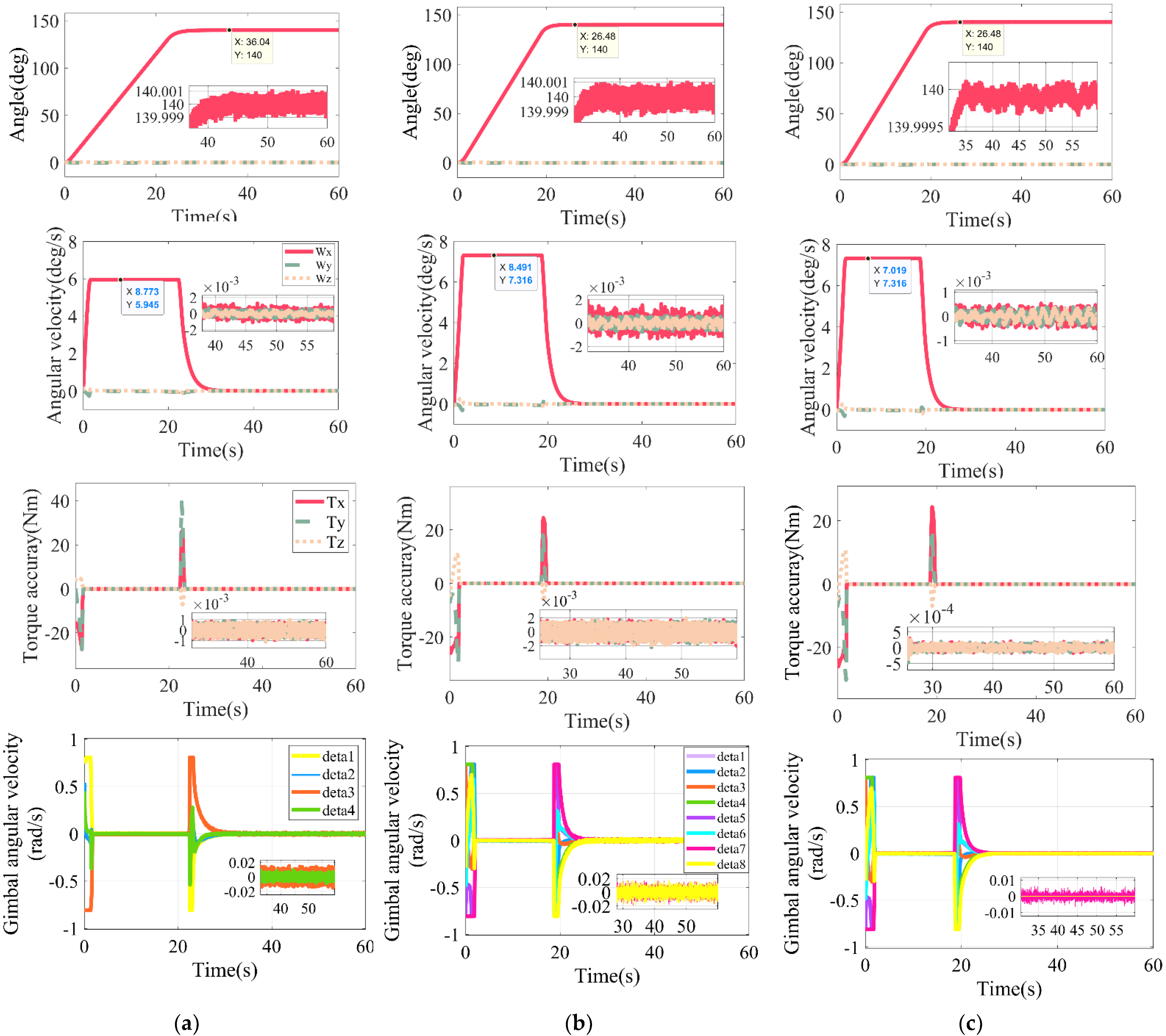
  • Case 2, a large angle of 140 deg around the x-axis attitude maneuver.
The small and large-angle simulation results (as shown in Figure 10 and Figure 11) are the attitude metrics of different SGCMGs configurations, which include 4-SGCMGs, 8-SGCMGs, and reconfiguration of 8-SGCMGs into 4-SGCMGs. The t 0 + Δ t t 1   defined in the previous section is used as the maneuvering segment, and the maneuvering time of the three configurations is unified as t 1 . The fluctuation range of the instantaneous target attitude angle is defined as the attitude angle error θ e , which reflects the pointing accuracy of the hyper-agile satellite. In addition, we define the fluctuation range of the instantaneous attitude angular velocity as the attitude angular velocity error ω e r r o r , which reflects the attitude maneuver stability. The difference between the desired torque of the controller and the actual torque is defined as the moment accuracy T a c c u r a c y , which reflects the variation of the torque output fineness. With similar total momentum envelopes, the first two rows (seen in Figure 10 and Figure 11) suggest that the hyper-agile satellites configured with 8-SGCMGs have shorter maneuver times and higher maximum attitude angular velocities ω max compared to 4-SGCMGs, but the pointing accuracy and stability in the stabilization segment are almost the same. This verifies the analysis above about the superior momentum output capability of 8-SGCMGs compared to other configurations. After the reconfigurable design proposed in this paper is introduced in the 8-SGCMGs, the pointing accuracy and stability are significantly reduced (see the first two rows of Figure 10 and Figure 11), and the torque accuracy and gimbal angular velocity fluctuation are reduced by more than double (see the last two rows of Figure 10 and Figure 11), which confirms that the locked gimbals will reduce the interference of the radial load friction torque to the system. Additionally, the last two rows of Figure 11 indicate that the torque output capability and gimbal angular velocity utilization of the 8-SGCMGs do not reach the limit value in the large-angle attitude maneuver, and that leaves much room for improvement. The detailed simulation comparison results mentioned above are organized in Table 9.
Result 1, Small-angle Attitude Maneuver (20 deg)
Result 2, Large-angle Attitude Maneuver (140 deg)
In summary, the reconfigurable design solves the problem that low-cost miniaturized SGCMGs are difficult to break the stability limit, reduces the design difficulty of control algorithms and steering laws, and has unique advantages in balancing the trade-off between maneuverability and stability.

6. Conclusions

In this paper, motivated by the development of future low-cost and fast-revisit of Jilin-1 hyper-agile satellite, reconfigurable 8-SGCMGs to 4-SGCMGs are proposed as actuators. To overcome the stability bottleneck, this study focuses on the rotor radial load friction interference caused by the gimbal rotation. Combined with the physical modeling and experimental analysis of torque disturbance, the unknown frictional disturbance is understood to a greater extent. This design not only solves the interference problem of SGCMG from the basic, but also greatly reduces the difficulty of controller design, and improves the satellite attitude performance parameters. In addition, the new evaluation metrics of the configurations are defined by norm L and norm L 2 , and the 8-SGCMGs are proved to have the best overall momentum output capability by comparison with typical configurations. Based on this, the full modeling of ACS is completed, including dynamics, kinematics, control algorithm, reconfigurable SGCMGs system, environmental disturbances and sensors, etc. The conditions for the configuration switching of SGCMGs in the attitude maneuver segment and the attitude stabilization segment are defined. In the attitude maneuver segment, the 8 units of SGCMGs work together to improve the maneuver performance by outputting large torque with low accuracy. In the attitude stabilization segment, the gimbals of 4 units of SGCMGs are lockout and the 4-SGCMGs are reconstituted to output fine torque. By only configuring PD controller and singular robust steering law, this design can provide a trade-off between high maneuverability and stability during attitude maneuver.

Author Contributions

Conceptualization, Z.Q., G.Z. and K.X.; methodology, Z.Q., G.Z. and Z.M.; Formal analysis, Z.Q., G.Z. and Z.M.; Investigation, R.X. and J.D.; Software, Z.Q.; Supervision, R.X. and J.D.; Writing—original draft, Z.Q.; Writing—review and editing, Z.M. All authors have read and agreed to the published version of the manuscript.

Funding

This work has been financially supported by Science and Technology on Space Intelligent Control Laboratory, No. 2021-JCJQ-LB-010-16.

Institutional Review Board Statement

Not applicable.

Informed Consent Statement

Not applicable.

Data Availability Statement

Not applicable.

Conflicts of Interest
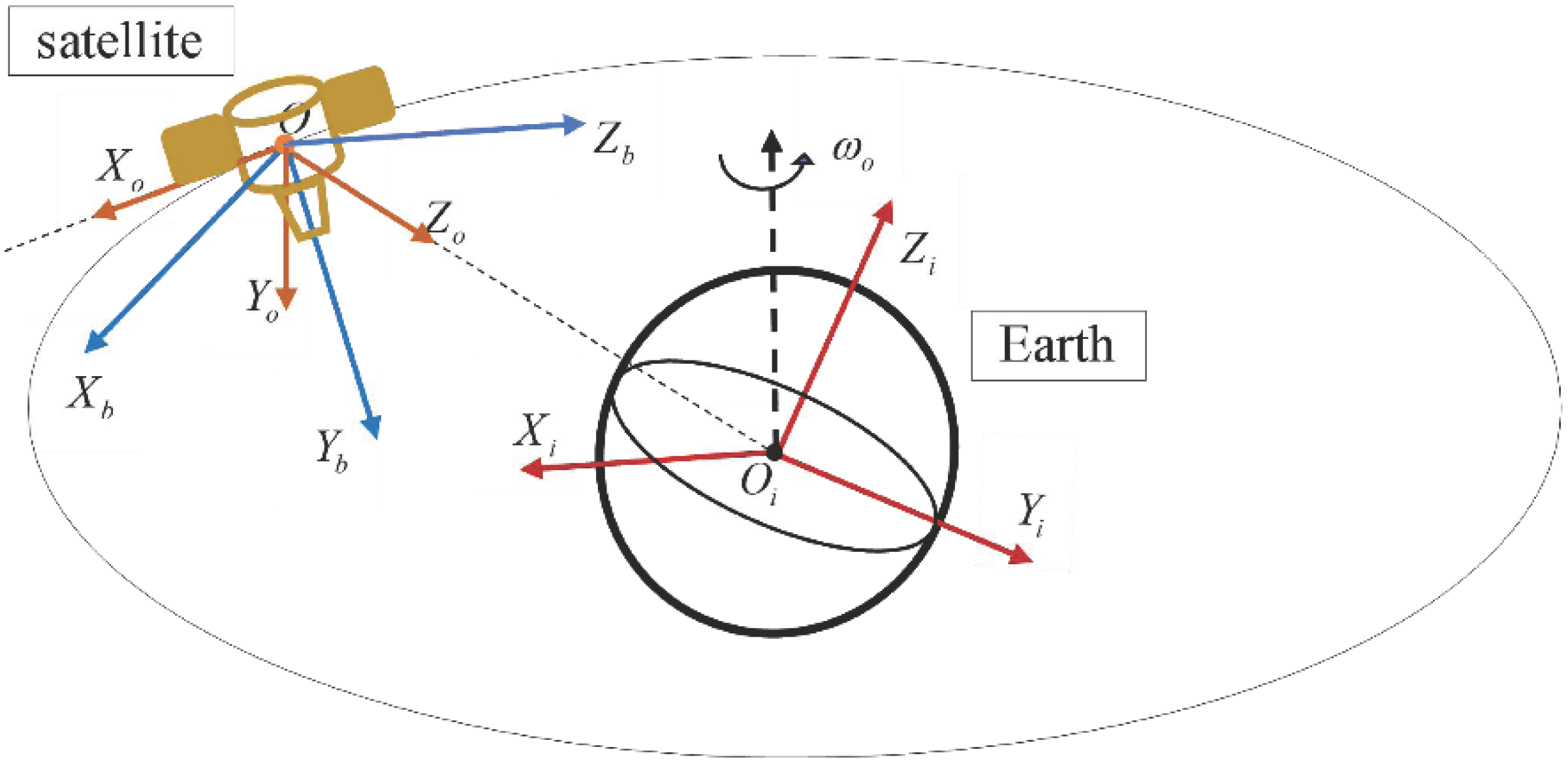
The authors declare no conflict of interest.

Appendix A

To describe the hyper-agile satellite attitude, we define the spatial coordinate system, which includes the inertial coordinate system, orbital coordinate system, and satellite body coordinate system. The spatial coordinate system is shown in Figure A1.
Figure A1. Spatial coordinate system.
Aerospace 09 00303 g0a1
  • Inertial Coordinate System
The coordinate system O i X i Y i Z i is an inertial coordinate system with the center O i of the Earth as the origin, the line of intersection along the equatorial and ecliptic planes of the Earth as O i X i axis, the O i X i axis pointing to the equinox, and the O i Z i axis pointing to the North Pole of the Earth, and the other axis determined by the right-handed orthogonal system as the O i Y i axis.
2.
Orbital Coordinate System
Coordinate system O X o Y o Z o is the orbital coordinate system, which is an orthogonal coordinate system with the satellite center of mass O as the origin, O Z o axis is pointing to the geocentric direction, the O X o and O Y o axis are perpendicular in the orbital plane, O X o axis is the satellite forward direction, and O Y o axis is parallel to the normal of the orbital plane, and the three axes of the coordinate system conform to the right-handed orthogonal system.
3.
Body Coordinate System
The coordinate system O X b Y b Z b is the satellite body coordinate system, while the center of mass O of the satellite is defined as the origin of this coordinate system. The roll axis, pitch axis, and yaw axis are defined as O X b , O Y b , and O Z b axis, respectively, and conform to the right-handed orthogonal coordinate system. The body coordinate system coincides with the orbital coordinate system when the satellite is in the three-axis stabilization phase to the Earth.

References

  1. Xie, Y.; Lei, Y.; Guo, J.; Meng, B. Spacecraft Dynamics and Control; Space Science and Technologies; Springer: Singapore, 2022; ISBN 978-981-336-447-9. [Google Scholar]
  2. Drusch, M.; Del Bello, U.; Carlier, S.; Colin, O.; Fernandez, V.; Gascon, F.; Hoersch, B.; Isola, C.; Laberinti, P.; Martimort, P.; et al. Sentinel-2: ESA’s Optical High-Resolution Mission for GMES Operational Services. Remote Sens. Environ. 2012, 120, 25–36. [Google Scholar] [CrossRef]
  3. Berger, M.; Aschbacher, J. Preface: The Sentinel Missions—New Opportunities for Science. Remote Sens. Environ. 2012, 120, 1–2. [Google Scholar] [CrossRef]
  4. ESA Earth Observation Portal. Copernicus: Sentinel-1—The SAR Imaging Constellation for Land and Ocean Services. Available online: https://directory.eoportal.org/web/eoportal/satellite-missions/c-missions/copernicus-sentinel-1 (accessed on 26 May 2022).
  5. Thieuw, A.; Marcille, H. Pleiades-Hr CMGs-Based Attitude Control System Design, Development Status and Performances. IFAC Proc. Vol. 2007, 40, 834–839. [Google Scholar] [CrossRef]
  6. Kruse, F.A.; Baugh, W.M.; Perry, S.L. Validation of DigitalGlobe WorldView-3 Earth Imaging Satellite Shortwave Infrared Bands for Mineral Mapping. J. Appl. Remote Sens. 2015, 9, 096044. [Google Scholar] [CrossRef]
  7. Xu, S.; Lu, Z.; Zhang, X.; Liao, W. Attitude Stability Control of Micro-Nano Satellite Orbit Maneuver Based on Bias Momentum. J. Phys. Conf. Ser. 2021, 2083, 022060. [Google Scholar] [CrossRef]
  8. Lappas, V.J.; Steyn, W.H.; Underwood, C.I. Attitude Control for Small Satellites Using Control Moment Gyros. Acta Astronaut. 2002, 51, 101–111. [Google Scholar] [CrossRef] [Green Version]
  9. Mkrtychyan, A.R.; Bashkeev, N.I.; Yakimovskii, D.O.; Akashev, D.I.; Yakovets, O.B. Control Moment Gyroscopes for Spacecraft Attitude Control Systems: Current Status and Prospects. Gyroscopy Navig. 2015, 6, 236–240. [Google Scholar] [CrossRef]
  10. Zhang, Y.; Zhang, J. Disturbance Characteristics Analysis of CMG Due to Imbalances and Installation Errors. IEEE Trans. Aerosp. Electron. Syst. 2014, 50, 1017–1026. [Google Scholar] [CrossRef]
  11. Cui, P.; Zhang, D.; Yang, S.; Li, H. Friction Compensation Based on Time-Delay Control and Internal Model Control for a Gimbal System in Magnetically Suspended CMG. IEEE Trans. Ind. Electron. 2017, 64, 3798–3807. [Google Scholar] [CrossRef]
  12. Lee, S.; Jung, S. Experimental Verification of Singularity-Robust Torque Control for a 1.2-Nm–5-Hz SGCMG. IEEE Trans. Ind. Electron. 2018, 65, 4871–4879. [Google Scholar] [CrossRef]
  13. Kojima, H. Singularity Analysis and Steering Control Laws for Adaptive-Skew Pyramid-Type Control Moment Gyros. Acta Astronaut. 2013, 85, 120–137. [Google Scholar] [CrossRef]
  14. Takada, K.; Kojima, H.; Matsuda, N. Control Moment Gyro Singularity-Avoidance Steering Control Based on Singular-Surface Cost Function. J. Guid. Control Dyn. 2010, 33, 1442–1450. [Google Scholar] [CrossRef]
  15. Kawajiri, S.; Matunaga, S. A Low-Complexity Attitude Control Method for Large-Angle Agile Maneuvers of a Spacecraft with Control Moment Gyros. Acta Astronaut. 2017, 139, 486–493. [Google Scholar] [CrossRef]
  16. Hu, Q.; Guo, C.; Zhang, J. Singularity and Steering Logic for Control Moment Gyros on Flexible Space Structures. Acta Astronaut. 2017, 137, 261–273. [Google Scholar] [CrossRef]
  17. Hou, Z.; Geng, Y.; Wu, B.; Huang, S. Spacecraft Angular Velocity Trajectory Planning for SGCMG Singularity Avoidance. Acta Astronaut. 2018, 151, 284–295. [Google Scholar] [CrossRef]
  18. Leeghim, H.; Lee, C.-Y.; Jin, J.; Kim, D. A Singularity-Free Steering Law of Roof Array of Control Moment Gyros for Agile Spacecraft Maneuver. Int. J. Control Autom. Syst. 2020, 18, 1679–1690. [Google Scholar] [CrossRef]
  19. Seo, H.-H.; Bang, H.; Cheon, Y.-J. Steering Law of Control Moment Gyros Using Artificial Potential Function Approach. Acta Astronaut. 2019, 157, 374–389. [Google Scholar] [CrossRef]
  20. Zhang, J.; Ma, K.; Meng, G.; Tian, S. Spacecraft Maneuvers via Singularity-Avoidance of Control Moment Gyros Based on Dual-Mode Model Predictive Control. IEEE Trans. Aerosp. Electron. Syst. 2015, 51, 2546–2559. [Google Scholar] [CrossRef]
  21. Elkhayat, M.A.; Elhalwagy, Y.; ElRaffie, A.Y.; Elnashar, G.A. Robust Nonlinear Combined Attitude Control Algorithm Using Control Moment Gyro for Agile Satellites. In Proceedings of the AIAA SPACE 2016, Long Beach, CA, USA, 13–16 September 2016. [Google Scholar]
  22. Ozawa, R.; Takahashi, M. Agile Attitude Maneuver via SDRE Controller Using SGCMG Integrated Satellite Model. In Proceedings of the 2018 AIAA Guidance, Navigation and Control Conference, Kissimmee, FL, USA, 8–12 January 2018. [Google Scholar]
  23. Hu, Q.; Tan, X. Dynamic Near-Optimal Control Allocation for Spacecraft Attitude Control Using a Hybrid Configuration of Actuators. IEEE Trans. Aerosp. Electron. Syst. 2020, 56, 1430–1443. [Google Scholar] [CrossRef]
  24. Yu, X.; Zhu, Y.; Qiao, J.; Guo, L. Antidisturbance Controllability Analysis and Enhanced Antidisturbance Controller Design with Application to Flexible Spacecraft. IEEE Trans. Aerosp. Electron. Syst. 2021, 57, 3393–3404. [Google Scholar] [CrossRef]
  25. Kristiansen, R.; Nicklasson, P.J.; Gravdahl, J.T. Satellite Attitude Control by Quaternion-Based Backstepping. IEEE Trans. Control Syst. Technol. 2009, 17, 227–232. [Google Scholar] [CrossRef]
  26. Giuseppi, A.; Pietrabissa, A.; Cilione, S.; Galvagni, L. Feedback Linearization-Based Satellite Attitude Control with a Life-Support Device without Communications. Control Eng. Pract. 2019, 90, 221–230. [Google Scholar] [CrossRef]
  27. Verbin, D.; Lappas, V.J. Rapid Rotational Maneuvering of Rigid Satellites with Hybrid Actuators Configuration. J. Guid. Control Dyn. 2013, 36, 532–547. [Google Scholar] [CrossRef]
  28. Yamada, K.; Jikuya, I.; Kwak, O. Rate Damping of a Spacecraft Using Two Single-Gimbal Control Moment Gyros. J. Guid. Control Dyn. 2013, 36, 1606–1623. [Google Scholar] [CrossRef]
  29. Yoshimura, Y. Optimal Fault-Tolerant Configurations of Control Moment Gyros. J. Guid. Control Dyn. 2015, 38, 2460–2467. [Google Scholar] [CrossRef]
  30. Yue, C.; Kumar, K.D.; Shen, Q.; Goh, C.H.; Lee, T.H. Attitude Stabilization Using Two Parallel Single-Gimbal Control Moment Gyroscopes. J. Guid. Control Dyn. 2019, 42, 1353–1364. [Google Scholar] [CrossRef]
  31. Yue, C.; Wu, F.; Wang, F.; Cao, X.; Shen, Q.; Kumar, K.D. Two Parallel Single-Gimbal Control Moment Gyros Actuated Spacecraft Attitude Maneuver. IEEE Trans. Aerosp. Electron. Syst. 2020, 56, 4112–4123. [Google Scholar] [CrossRef]
  32. Geshnizjani, R.; Kornienko, A.; Ziegler, T.; Löhr, J.; Fichter, W. Torque Optimal Steering of Control Moment Gyroscopes for Agile Spacecraft. J. Guid. Control Dyn. 2021, 44, 629–640. [Google Scholar] [CrossRef]
  33. Lei, Y.; Yuan, L.; Zhu, Q.; Wang, Z.; Liu, J. A Steering Method with Multiobjective Optimizing for Nonredundant Single-Gimbal Control Moment Gyro Systems. IEEE Trans. Ind. Electron. 2022, 69, 4177–4184. [Google Scholar] [CrossRef]
  34. Karpenko, M.; King, J.T.; Dennehy, C.J.; Ross, I.M. Agility Analysis of the James Webb Space Telescope. J. Guid. Control Dyn. 2019, 42, 810–821. [Google Scholar] [CrossRef]
  35. Zhang, L.; Yu, C.; Zhang, S.; Cai, H. Optimal Attitude Trajectory Planning Method for CMG Actuated Spacecraft. Proc. Inst. Mech. Eng. Part G J. Aerosp. Eng. 2018, 232, 131–142. [Google Scholar] [CrossRef]
  36. Markley, F.L.; Reynolds, R.G.; Liu, F.X.; Lebsock, K.L. Maximum Torque and Momentum Envelopes for Reaction Wheel Arrays. J. Guid. Control Dyn. 2010, 33, 1606–1614. [Google Scholar] [CrossRef]
  37. Chen, S.; Xuan, M.; Xin, J.; Liu, Y.; Gu, S.; Li, J.; Zhang, L. Design and Experiment of Dual Micro-Vibration Isolation System for Optical Satellite Flywheel. Int. J. Mech. Sci. 2020, 179, 105592. [Google Scholar] [CrossRef]
  38. Qu, Z.; Jia, H.; Xu, K.; He, X.; Yang, F.; Li, F.; Liu, M. Reconfigurability Analysis of Distributed Control Moment Gyro for Jilin-1 Super Agile Satellite. In Proceedings of the 2020 3rd International Conference on Electron Device and Mechanical Engineering (ICEDME), Suzhou, China, 1–3 May 2020. [Google Scholar]
  39. Inumoh, L.; Pechev, A.; Horri, N.; Forshaw, J. Three-Axis Attitude Control of a Satellite in Zero Momentum Mode Using a Tilted Wheel Methodology. In Proceedings of the AIAA Guidance, Navigation, and Control Conference, Minneapolis, MN, USA, 13–16 August 2012. [Google Scholar]
  40. Powell, B.K. Gravity-Gradient Momentum Management. J. Spacecr. Rockets 1972, 9, 385–386. [Google Scholar] [CrossRef]
  41. Frik, M.A. Attitude Stability of Satellites Subjected to Gravity Gradient and Aerodynamic Torques. AIAA J. 1970, 8, 1780–1785. [Google Scholar] [CrossRef]
  42. Stuck, B.W. Solar Pressure Three-Axis Attitude Control. J. Guid. Control 1980, 3, 132–139. [Google Scholar] [CrossRef]
  43. Zhang, Y.; Yang, L.; Zhu, Y.; Huang, H.; Cai, W. Angular-Momentum Management of Spacecraft Electromagnetic Docking Considering the Earth’s Magnetic Field. J. Guid. Control Dyn. 2013, 36, 860–869. [Google Scholar] [CrossRef]
  44. Lefferts, E.J.; Markley, F.L.; Shuster, M.D. Kalman Filtering for Spacecraft Attitude Estimation. J. Guid. Control Dyn. 1982, 5, 417–429. [Google Scholar] [CrossRef]
  45. Xiong, K.; Liang, T.; Yongjun, L. Multiple Model Kalman Filter for Attitude Determination of Precision Pointing Spacecraft. Acta Astronaut. 2011, 68, 843–852. [Google Scholar] [CrossRef]
  46. Zhang, Y.; Li, M.; Song, Z.; Shan, J.; Guan, X.; Tang, L. Design and Analysis of a Moment Control Unit for Agile Satellite with High Attitude Stability Requirement. Acta Astronaut. 2016, 122, 90–105. [Google Scholar] [CrossRef]
  47. Kawak, B.J. Development of a Low-Cost, Low Micro-Vibration CMG for Small Agile Satellite Applications. Acta Astronaut. 2017, 131, 113–122. [Google Scholar] [CrossRef]
  48. Hamilton-Jacobi Perturbation Theory. In Orbital and Celestial Mechanics; Progress in Astronautics and Aeronautics, 23 August 2012; American Institute of Aeronautics and Astronautics: Reston, VA, USA, 2012. [CrossRef]
  49. Kurokawa, H. Survey of Theory and Steering Laws of Single-Gimbal Control Moment Gyros. J. Guid. Control Dyn. 2007, 30, 1331–1340. [Google Scholar] [CrossRef]
  50. Sands, T.A.; Kim, J.J.; Agrawal, B.N. Nonredundant Single-Gimbaled Control Moment Gyroscopes. J. Guid. Control Dyn. 2012, 35, 578–587. [Google Scholar] [CrossRef] [Green Version]
  51. Yamada, K.; Jikuya, I. Directional Passability and Quadratic Steering Logic for Pyramid-Type Single Gimbal Control Moment Gyros. Acta Astronaut. 2014, 102, 103–123. [Google Scholar] [CrossRef]
Figure 1. Attitude control system of hyper-agile satellites.
Aerospace 09 00303 g001
Figure 2. Composition schematic of SGCMG and 8-SGCMGs. (a) SGCMG, (b) 8-SGCMGs.
Aerospace 09 00303 g002
Figure 3. Momentum characteristics of 8-SGCMGs. (a) Momentum envelope, (b) Sample arrangement, (c) Sample number statistics.
Aerospace 09 00303 g003
Figure 4. Failure momentum envelops of 8-SGCMGs. (a) Asymmetric failure, (b) Symmetric failure.
Aerospace 09 00303 g004
Figure 5. Singularity schematic diagram of the SGCMGs.
Aerospace 09 00303 g005
Figure 6. Singular momentum envelopes of 8-SGCMGs.
Aerospace 09 00303 g006
Figure 7. Schematic diagram of SGCMG system.
Aerospace 09 00303 g007
Figure 8. Experimental setup. (a) SGCMG prototype, (b) Octagonal cone-type SGCMGs.
Aerospace 09 00303 g008
Figure 9. Reconfiguration of 8-SGCMGs into 4-SGCMGs.
Aerospace 09 00303 g009
Figure 10. Simulation results of small-angle attitude maneuver. (a) Large 4-SGCMGs, (b) 8-SGCMGs, (c) Reconfiguration of 8-SGCMGs into 4-SGCMGs.
Aerospace 09 00303 g010
Figure 11. Simulation results of large-angle attitude maneuver. (a) Large 4-SGCMGs, (b) 8-SGCMGs, (c) Reconfiguration of 8-SGCMGs into 4-SGCMGs.
Aerospace 09 00303 g011
Table 1. Statistic of momentum and failure momentum envelops of 8-SGCMGs.
Statistical Parameters
(h0 = 1 Nms)
Value Interval
[ Z m i n , Z m a x ]
Mean
Z m e a n
Median
Z m e d i a n
Standard   Deviation   σ Z
ValueNo failure h = 1   1   1   1   1   1   1   1 [ 5.947 , 6.614 ] 6.2266.1650.195
1 failed unit h = 0   1   1   1   1   1   1   1 [ 4.947 , 6.089 ] 5.4265.4470.269
2 failed units h = 0   0   1   1   1   1   1   1 [ 3.966 , 5.542 ] 4.6414.6630.391
h = 0   1   0   1   1   1   1   1 [ 3.948 , 5.123 ] 4.6994.6660.301
h = 0   1   1   0   1   1   1   1 [ 4.032 , 5.217 ] 4.673 4.6680.255
h = 0   1   1   1   0   1   1   1 [ 4.117 , 5.347 ] 4.6414.6690.254
3 failed units h = 0   0   0   1   1   1   1   1 [ 2.967 , 4.819 ] 3.8213.8230.449
h = 0   0   1   0   1   1   1   1 [ 3.032 , 4.544 ] 3.9073.8620.353
h = 0   0   1   1   0   1   1   1 [ 3.117 , 4.631 ] 3.8333.8700.308
h = 0   1   0   1   0   1   1   1 [ 3.136 , 4.347 ] 3.9143.8610.249
h = 0   1   0   1   1   0   1   1 [ 3.467 , 4.306 ] 3.8713.8730.178
4 failed units h = 0   0   0   0   1   1   1   1 [ 2.051 , 3.948 ] 3.1133.0700.481
h = 0   0   0   1   0   1   1   1 [ 2.136 , 3.825 ] 3.1103.0930.377
h = 0   0   1   1   0   1   0   1 [ 2.468 , 3.632 ] 3.0993.108 0.227
h = 0   0   1   1   0   0   1   1 [ 2.550 , 3.820 ] 3.0893.0890.304
h = 0   0   0   1   1   0   1   1 [ 2.486 , 3.875 ] 3.0573.0980.336
h = 0   0   1   0   0   1   1   1 [ 2.117 , 3.673 ] 3.142 3.0870.349
h = 0   1   0   1   0   1   0   1 [ 2.818 , 3.347 ] 3.0893.1140.116
Table 2. Statistic of singular momentum envelops of 8-SGCMGs.
Statistical Parameters
(h0 = 1 Nms)
Value Interval
[ Z m i n , Z m a x ]
Mean
Z m e a n
Median
Z m e d i a n
Standard Deviation
σ Z
Value8H ε = 1 1 1 1 1 1 1 1 [ 0 , 6.532 ] 2.8723.0832.103
6H ε = 1 1 1 1 1 1 1 1 [ 0 , 5.543 ] 2.3582.5351.617
4H ε = 1 1 1 1 1 1 1 1 [ 0 , 4.368 ] 2.0811.9721.127
2H ε = 1 1 1 1 1 1 1 1 [ 0 , 3.068 ] 1.4321.3280.668
0H ε = 1 1 1 1 1 1 1 1 [ 0 , 1.732 ] 0.3880.5950.577
Table 3. Typical configuration performance parameters.
Typical ConfigurationMEFMESMEEvaluation Metric
γ L γ L 2 λ L λ L 2 χ L χ L 2 ν L ν L 2
4-SGCMGs0.70780.7879000.65660.32541.36441.1133
5-SGCMGs0.71650.79490.31730.40150.68910.26991.72291.4663
6-SGCMGs0.64630.82170.24750.32420.74870.30511.64251.4510
8-SGCMGs0.74340.77870.37120.44440.52510.28311.63971.5062
Table 4. Main parameters of SGCMG prototype.
Parameter NameValue
Equatorial rotational inertia of the flywheel J r 0.0057   kg · m 2
Rotational inertia of pole J z 0.012   kg · m 2
Maximum gimbal angular acceleration of θ ¨ f M A X 0.8236   rad / s 2
Maximum gimbal angular velocity θ ˙ f M A X 0.8086   rad / s
Rated speed of flywheel ω r 4000   rpm
Rated angular momentum of flywheel H f 7   Nm · s
Rated torque of SGCMG M G 5.6   Nm
Table 5. Gimbal angular velocity and disturbance torque data.
Output Torque
M G / N m
Gimbal Angular Velocity
θ ˙ f / r a d / s
Flywheel Disturbance Torque
T b / N m
0.26110.03730.00511
0.8610.1230.01122
1.46090.20870.01299
2.06080.29440.01353
2.66070.38010.01448
3.26060.46580.01599
3.86050.55150.01671
4.46040.63720.01780
5.06030.72290.01896
5.66020.80860.02163
Table 6. Function of control and steering allocation.
Function for Determining 8-SGCMGs Control Allocation
Aerospace 09 00303 i001
Table 7. Simulation parameters.
ParameterValue
Momentum of inertia J 245   0   0 , 0   255   0 , 0   0   190   kg · m 2
Initial angle θ 0 0   0   0 deg
Initial angular velocity 0   0   0 deg / s
Mass of satellite1000 kg
SGCMG flywheel momentum (large size 4-SGCMGs) h 0 14 Nms
SGCMG flywheel momentum (8-SGCMGs) h 0 7 Nms
Maximum gimbal rate 0.8086 rad / s
Orbit inclination90 deg
Orbit altitude560 km
Proportional gain K p 8400   7820.4   3368.4 s 2
Derivative gain K d 5940   5530.14   2381.94 s 2
Factor of the null motion χ 0.3
Singularity parameter , λ , μ , Q i # 0.01, 0.3, 20, 1
Periodic perturbation parameter ε i 0.01
Table 8. Disturbance simulation parameters.
ParameterValue
Stellar sensitive noise [ σ x   σ y   σ z ] [ 50   10   10 ]
Fiber optic gyro initial zero bias c t 0 [ 55   55   55 ] / s
Fiber optic gyro angle random wandering σ ARW 0.07 deg / h 0.5
Fiber optic gyro angular rate random wandering σ ARRW 0.15 deg / h 1.5
Characteristic area of windward S 1 m 2
Drag coefficient of aerodynamic C d 2.6
Position vector of the center of pressure concerning the center of satellite mass ρ S 0.1   0.1   0.1
Sunlight pressure area O 1 m 2
Reflectivity of the surface R 0.5
Transmissibility of the surface ν 0.2
Force arm of sunlight pressure M r 0.1   0.1   0.1
Remanent magnetic moment M b 0.02   0.02   0.02 A · m 2
Table 9. Simulation results of attitude maneuver.
MetricsCase1 (20 deg)Case2 (140 deg)
Large 4-SGCMGs8-SGCMGsReconfiguration of 8-SGCMGs into 4-SGCMGsLarge 4-SGCMGs8-SGCMGsReconfiguration of 8-SGCMGs into 4-SGCMGs
Maneuver time t 1 / ( s ) 15.1812.8212.7836.0426.4826.48
Angle error θ e / ( deg ) ± 0.0012 ± 0.0012 ± 0.0005 ± 0.0014 ± 0.0014 ± 0.0005
Maximum angular velocity
ω max / ( deg / s )
5.9457.3167.3165.9457.3167.316
Angular velocity error
ω e r r o r / ( deg / s )
± 0.001 ± 0.0012 ± 0.0005 ± 0.002 ± 0.002 ± 0.001
Torque accuracy
T a c c u r a c y / ( Nm )
± 0.001 ± 0.0015 ± 0.0005 ± 0.0012 ± 0.002 ± 0.0005
Publisher’s Note: MDPI stays neutral with regard to jurisdictional claims in published maps and institutional affiliations.

