1. Introduction
Following the launch of Luna-1 by the USSR in 1959 [
1], the exploration of the Moon has never stopped. With the success of the Apollo Project [
2], human exploration of the Moon reached a peak. In recent decades, Japan, the ESA, China, India and other countries have successively begun their own Lunar exploration programs [
3,
4,
5,
6]. Thanks to a series of missions, e.g., SMART-1, the Chinese Lunar Exploration Program, Clementine, Lunar Prospector, and the Lunar Reconnaissance Orbiter, humanity has made great progress in cognizing the Moon in the aspects of surface environment, gravity field, geological composition and utilization of cislunar space [
7,
8,
9,
10,
11,
12].
With the method of spherical harmonic analysis and differentiation of the Doppler residuals, the model of the Lunar gravity field has gradually improved according to the tracking data of previous missions and the concept of mascons (mass concentrations) has been proposed by [
13]. By analyzing the Lunar Prospector mission, a high precision model of Lunar gravity field has been established and the precision of the models is being continually improved. LP75D, LP75G, LP100J, LP100K, and LP165P has been published in succession. Among these models, LP165P provides the best accuracy [
14] all of the LP gravity models are available on the website named Planetary Data System [
15]. The establishment of the Lunar gravity models has laid the groundwork for subsequent research in the aspects of designs for the Moon missions, researches of Lunar frozen orbits and analysis of Lunar spacecraft lifetime.
Because of the masconian character of the Moon, a Moon orbiter, especially an ultra low-altitude ones, may have a collision with the surface of the Moon. There are two main routes to solving the problem: one is to deploy orbiters in the frozen orbits around the Moon [
16,
17,
18], and the other one is to extend the lifetime of spacecraft through orbit maintenance methods [
19,
20].
In terms of finding frozen orbits, Park and Junkins found a family of near polar frozen orbit in the method of zeroing the Lagrange Planetary Equations [
21]. Lara obtained three families of frozen orbit by means of numerical continuation, with two of them made of linear stable orbits and the third one made up of unstable orbits [
22]. Elipe and Lara discovered three families of frozen orbits the method of numerically continuing natural families of periodic orbits [
16]. Abad et al., using the approach of averaging the Hamiltonian, obtaned insights on the critical inclination through an analytical model based on Lie–Deprit transforms and obtained families of frozen orbits around the moon [
23]. With von Zeipel’s method to obtain a transformation between mean and osculating elements, frozen orbits exhibit better behavior in terms of long-term stability [
17]. Maksim et al. propose that low- to mid-altitude frozen orbits can be used to arrange a small satellite lunar constellation and design a communication/navigation satellite systems based on the idea [
24]. However, frozen orbits can not always satisfy the requirements of mission design due to conflicts between the constrains of frozen orbits and scientific destinations of missions.
As for lifetime extension, NASA has studied the lifetimes of spacecraft with 100 km and 300 km perilunar altitude in near-circular orbit, and discussed the relationship between initial conditions and lifetime based on the Ferrari
Lunar gravitational model [
25]. Gupta and Sharma have analyzed the effects of altitude, inclination, right ascension of ascending node (RAAN), and Earth’s gravitation on the lifetime of Lunar spacecraft [
26]. Alarcon et al. were able to extend the lifetime of the2U CubeSat using pulsed plasma thrusters [
27]. Cordova Alarcon et al. classified Lunar orbits into several unstable regions by inclination and proposed an orbit maintenance strategy to extend the lifetime of 100 km-altitude lunar spacecraft. The lifetime of spacecraft in some stable regions is extended to over one year but the one in the unstable regions still remains several days. Besides, the altitude of spacecraft is gradually divergent, which is detrimental to the mission [
19]. The research about lifetime extension has usually concentrate on 100 km-altitude orbits around the Moon. In missions such as the Lunar Reconnaissance Orbiter and SELENE, the spacecraft need to insert into the orbits with only a few dozen kilometer altitude in order to obtain high resolution images and have higher precision detection [
10,
28]. As the abundant scientific achievements made by the LRO mission shown, it is necessary to launch ultra low-altitude Lunar spacecrafts to explore the Moon. Although chemical thrusters were deployed on the Lunar Reconnaissance Orbiter and the SELENE mission [
29], low-thrust propulsion system have been further developed in recent decades which has played a crucial role on a variety of satellite platforms [
30].
In this paper, a propulsion system is deployed for Lunar spacecraft due to advantages such as high impulse, high dry mass ratio, etc. An orbit maintenance strategy based on feedback control is proposed to realize ultra low-altitude (about 50 km and lower) orbit maintenance. Through the application of this strategy, the orbit of the spacecraft can be kept in an appropriate range around the target orbit. As our simulations show, the lifetime of Lunar spacecraft can be extended globally as well. Although the current Lunar spacecraft usually use the polar orbits to have global scan and locate potential resources, the spacecrafts in low inclination orbits which cover low-latitude area better are also important in the near future. With the orbit maintenance strategy proposed in this paper, the lifetime of spacecraft in low inclination orbit can be extended from several days to over one hundred days.
Based on the results of our simulations, the influence of initial inclination and RAAN on orbit maintenance is discussed. The stability of orbits with different initial conditions is varied. The effect of orbit maintenance varying with different magnitudes of propulsion system thrust is analyzed. Smaller thrust magnitudes are ineffective in the unstable areas, while larger thrust magnitudes can correct orbits with any initial inclination. However, the extra fuel consumption in the latter case cannot be ignored; thus, the lifetime extension versus fuel ratio is exhibited here as well. According to the results of our simulations, ultra low-altitude Lunar orbit detection can be realized.
The remaining parts of this paper are organized as follows. In
Section 2, a model of the dynamics is introduced and Lunar spacecraft lifetime without orbit maintenance is analyzed. In
Section 3 shows the illustration of the feedback control method and derivation of the orbit maintenance strategy proposed in this paper.
Section 4 is dedicated to discussion of numerical simulations results. Finally, the conclusions are summarized in
Section 5.
2. Lunar Spacecraft Lifetime Analysis
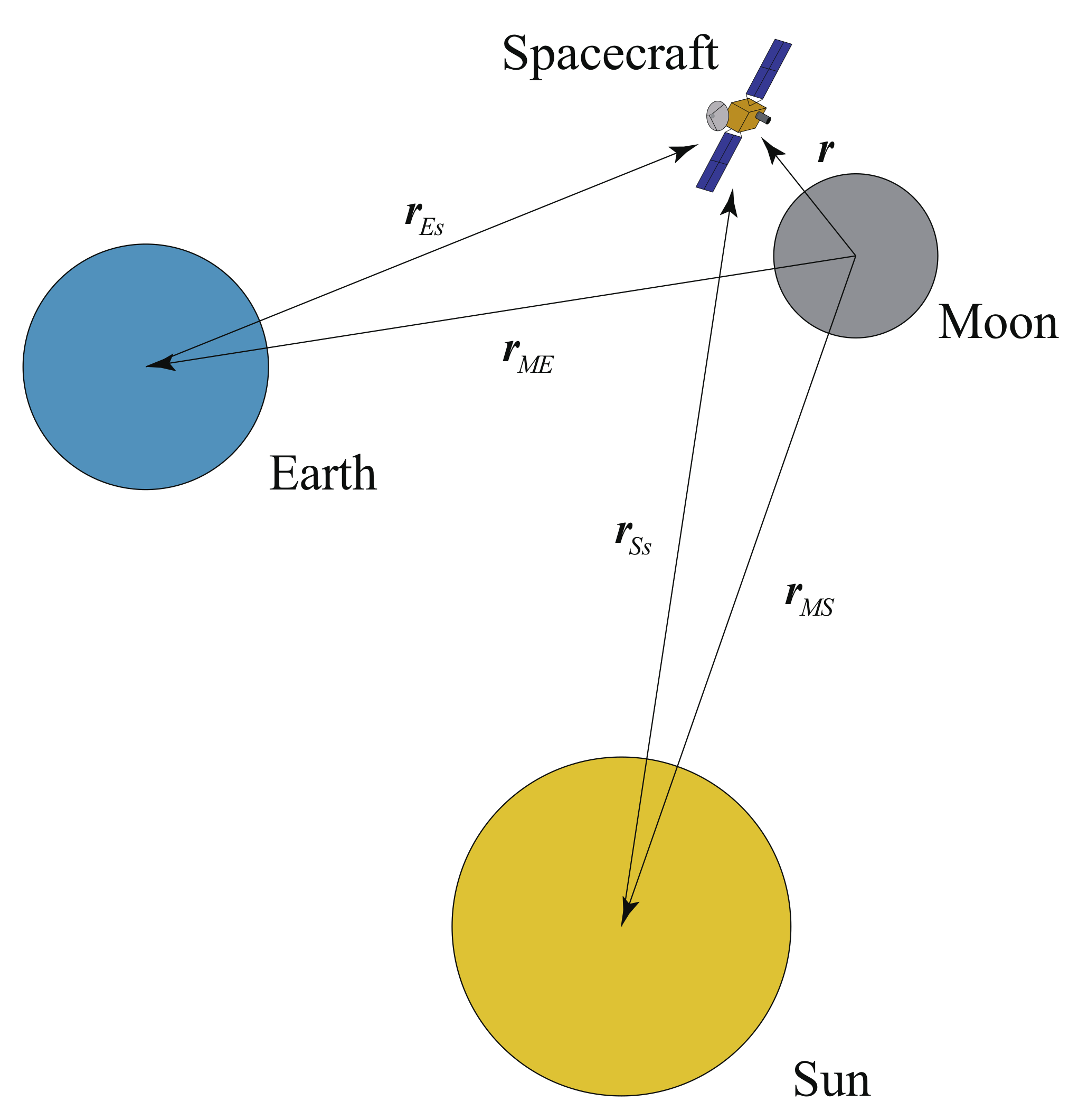
In the cislunar space, the spacecraft is mainly under the gravity influence of the Moon, the Earth and the Sun [
31]. The motion equation of the spacecraft as lunar orbiter can be written as
where
represents the position vector relative to the center of the Moon in the International Celestial Reference Frame (ICRF).
represents the gravitation of Moon,
and
are the third body perturbation of the Earth and the Sun respectively.
is the acceleration produced by the propulsion system of the spacecraft. The specific expression in Equation (
1) are provided by
where the term
represents the gravitational gradient of the Moon containing the Lunar gravity model LP165p, which reliably approximates the smallest mascon on the Moon in the Moon-centered Moon-fixed coordinate system (the matrix transforming these co-ordinates into the ICRF is provided in the IAU report [
32]); the term
represents the gravitational gradient of the Earth the containing non-sphere perturbation term
,
and
are the gravitational parameters of the Earth and the Sun, respectively, and
means the relative position vector pointing from
a to
b, which is illustrated in the
Figure 1. These relative position vectors in the ICRF can be obtained from the DE405 ephemeris released by the JPL.
In the influence of perturbation above, the low-altitude Lunar spacecraft may fall on the surface of the Moon. In numerical simulations, the lifetime of Lunar spacecraft ends when the distance between the spacecraft and Moon center is shorter than the radius of the Moon. The lifetime of Lunar spacecraft with different initial orbital elements can be obtained by integrating the Runge–Kutta–Fehlberg (RKF78) method, with the normalization of the integral provided by
with
representing the gravitational parameter of the Moon and
representing the mean radius of the Moon. The truncation error in the process of integral is set as
. For the ultra low-altitude spacecraft around the Moon, the order of the perturbation aforementioned are shown in
Table 1.
As shown in
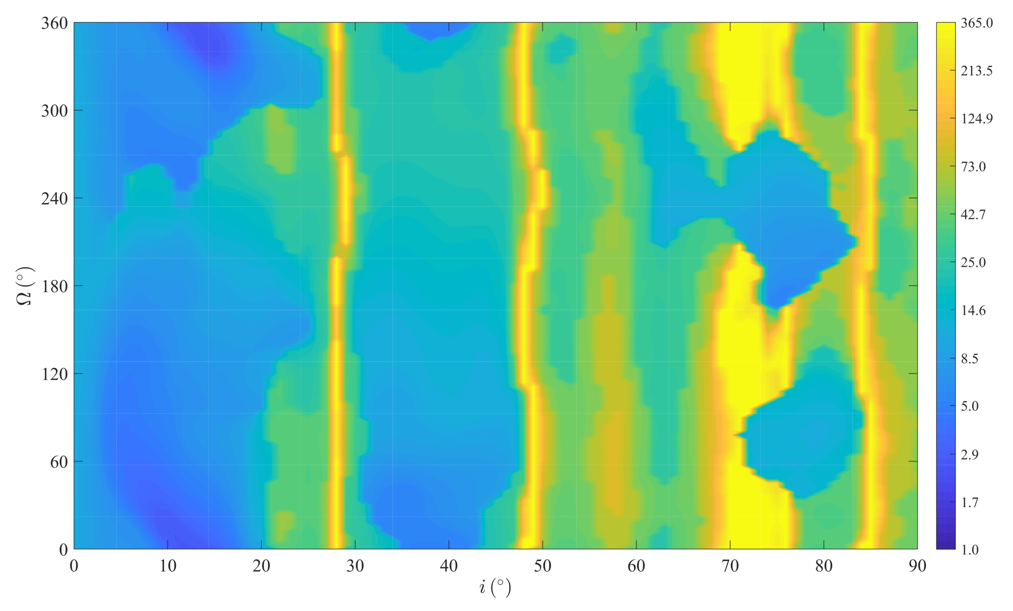
Table 1, the spacecraft is mainly affected by the non-sphere perturbation. In
Figure 2, the lifetime of Lunar spacecraft varying with initial inclination and RAAN is shown considering the epoch time set as 2030-1-1 00:00:00, initial semi-major axis is
and eccentricity is
.
As shown in the contour, the lifetime of about 50 km-altitude Lunar spacecraft without orbit maintenance is quite short in most situations. The horizontal axis represents the initial inclination of the Lunar spacecraft and the vertical axis represents the initial RAAN. Due to the large span of lifetime, the corresponding relationship between lifetime and contour color is logarithmic, which is exhibited as the colorbar on the right. The blue end is corresponding with short lifetime and the yellow end is with the long lifetime. Lifetime longer than a year is denoted as 365 days. As the contour shows, situations with a lifetime exceeding one year mainly concentrate around certain special initial inclinations, which coincides with the research on Lunar spacecraft lifetime [
25,
26]. For spacecraft in low-inclination orbits, the lifetime can be as short as several days, which means orbit maintenance is indispensable for low-inclination Lunar spacecraft. Along the horizontal direction, the figure shows the tendency of the change in lifetime with initial inclination. In the vertical direction, the figure reflects the lifetime versus initial RAAN. In the next section, an orbit maintenance strategy is proposed, which can extend the lifetime of ultra low-altitude Lunar spacecraft notably.
3. Orbit Maintenance Strategy
Low-thrust technology can be utilized to realize orbit maintenance in order to avoid collision between the spacecraft and the Lunar surface and to keep the spacecraft in an appropriate range around the target orbit. When the spacecraft drifts away from the original orbit in excess of the threshold, an orbital transfer from the current orbit to the target orbit is initiated, driven by the low-thrust propulsion system. The equations of low-thrust transfer are governed by the Lagrange Planetary Equations and mass-flow differential equation, which are provided by [
33]:
with
.
a,
e,
i,
,
and
M are the Kepler orbit elements.
n,
f and
E represent the mean motion, true anomaly and eccentric anomaly, respectively.
donates the specific impulse and
is the gravitational acceleration at sea level.
m represents the mass of the spacecraft.
donate the components of resultant acceleration which is produced by low-thrust propulsion force and perturbation effect. The base of
are defined by
where
and
are the position and velocity vectors of the spacecraft, respectively.
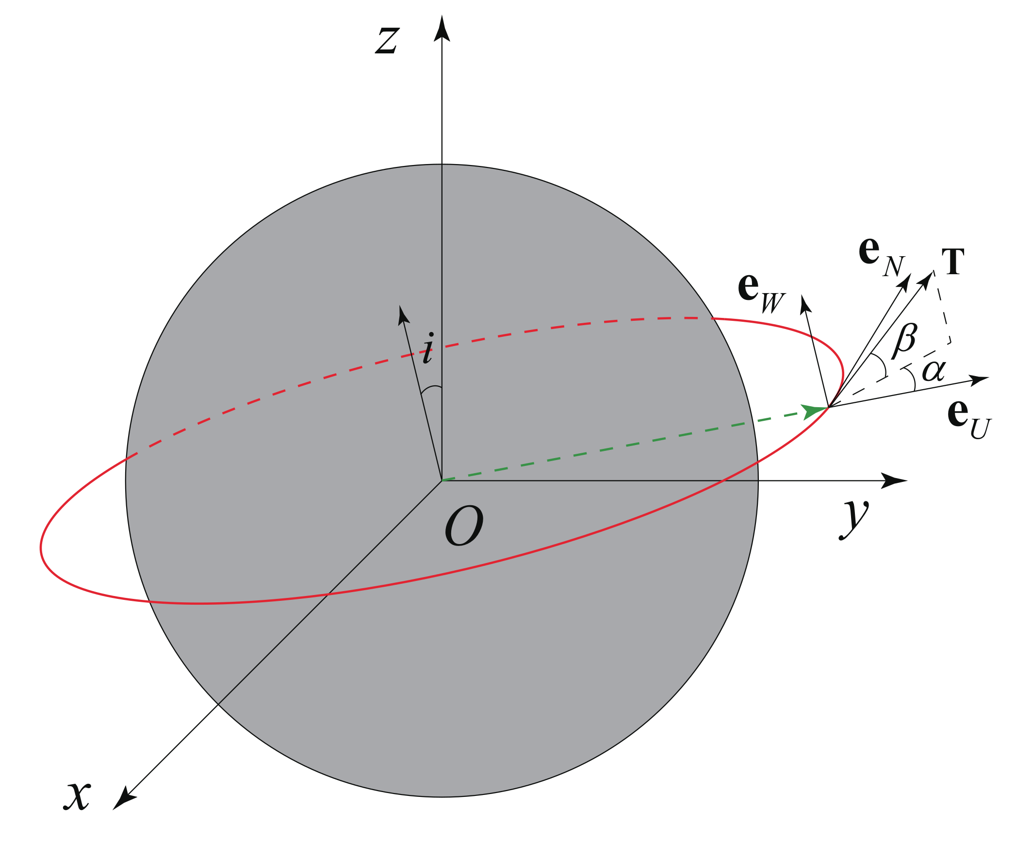
As shown in
Figure 3, the low-thrust acceleration can be described by
where
is the yaw angle in the orbit plane and
is the pitch angle out of the orbit plane.
In the process of low-thrust transfer from an arbitrary orbit in the neighborhood to the target orbit, the semi-major axis,
a, eccentricity,
e, and inclination,
i, of the target orbit are aimed. In order to make the spacecraft transfer to the target orbit as soon as possible, an intuitive control strategy is adopted. At every moment, the instantaneous change rate of the orbit elements
produced by the low-thrust propulsion system should be along the direction of
as much as possible (
), i.e., the performance index below,
F, should be maximized:
Although this control strategy is not optimal with respect to the influence of perturbation, it provides an efficient way of transferring the current orbit to the target one.
The maximization of performance index is provided by [
34],
where
with
and
satisfying
According to Equations (
8) and (
10), the near-optimal direction of thrust can be determined at every moment. In the process of orbit maintenance, the drift of each orbit element caused by perturbation is different. In order to improve the efficiency of this method, the weight coefficients can be added into Equation (
7), as follows:
Therefore, the coefficients in Equation (
9) are rewritten as
The weight coefficients can be selected by heuristic optimization algorithm with Equation (
11) set as performance index function. So far, the near optimal direction of thrust can be given by Equations (
9) and (
12).
Here is the detail statement of the orbit maintenance strategy. The spacecraft drifts away from the given target orbit elements (
) under the influence of the perturbation. Once the current orbit elements (
) exceed the tolerance of
, i.e.,
then the low-thrust propulsion system switches on. The spacecraft begins to transfer from the current orbit to the target orbit, with the direction of the thrust determined by Equations (
9)–(
12). The low-thrust propulsion system does not switch off until the orbit elements of the spacecraft satisfy the tolerance, (
), of the target orbit element, i.e.,
and when the fuel is depleted (i.e.,
), the orbit maintenance ends. The time from the beginning to the point when the fuel is depleted is the lifetime extended by the orbit maintenance strategy. After this, the spacecraft continues to run within the orbit until collision occurs. The orbit maintenance pseudo-code is provided as Algorithm 1.
represents the mass of the spacecraft at moment
t.
represents the dynamic equations Equation (
4) when low-propulsion system switches-on.
represents the dynamic equations Equation (
1) when low-propulsion system switches-off. ← is for the iteration of the variables.
| Algorithm 1 Orbit Maintenance |
- 1:
procedureOrbit Maintenance - 2:
- 3:
Propulsion system switch off - 4:
while do - 5:
if then - 6:
Propulsion system switch on - 7:
while and do - 8:
- 9:
- 10:
end while - 11:
Propulsion system switch off - 12:
end if - 13:
- 14:
- 15:
end while - 16:
end procedure
|
According to this strategy, orbit maintenance numerical simulations with different initial conditions are exhibited in the next section, which proves the validity of this strategy in lifetime extension and orbit maintenance.
4. Numerical Simulation and Discussion
The results of our numerical simulations applying the proposed orbit maintenance strategy for ultra low-altitude Lunar spacecraft are provided in this section. The numerical simulations are coded by Fortran language and run on Visual Studio 2019 and Intel oneAPI Toolkits.
Here, we set the epoch time as 2030-1-1 00:00:00,the initial semi-major axis as
, and the eccentricity as
. In the numerical simulation, the orbit maintenance strategy was tested with different initial inclination, RAAN, and magnitude of thrust. As the objective is to maintain the orbit, the target orbit was set equal to the initial one. The parameters of the Lunar spacecraft and tolerance in Equations (
13) and (
14) are shown in
Table 2. In the above conditions, the Lunar spacecraft is maintained in a near-circular orbit with an altitude of about 50 km and lower, which is a qualified orbit for a remote sensing satellite to obtain high resolution images. In the process of orbit maintenance, both the perturbation mentioned in
Section 2 and the shadow of the Moon are taken in consideration. When the spacecraft is in the shadow of the Moon, the low-thrust propulsion system maintains switch-off. The normalization is set as in Equation (
3), and the truncation error of the integrator is set as
in normalized units.
4.1. Magnitude of Thrust
As shown in
Figure 2, a different initial RAAN may cause a slight distinction in lifetime; however, the lifetime of spacecraft in low inclination orbits is relatively short. For example, with initial conditions of
and
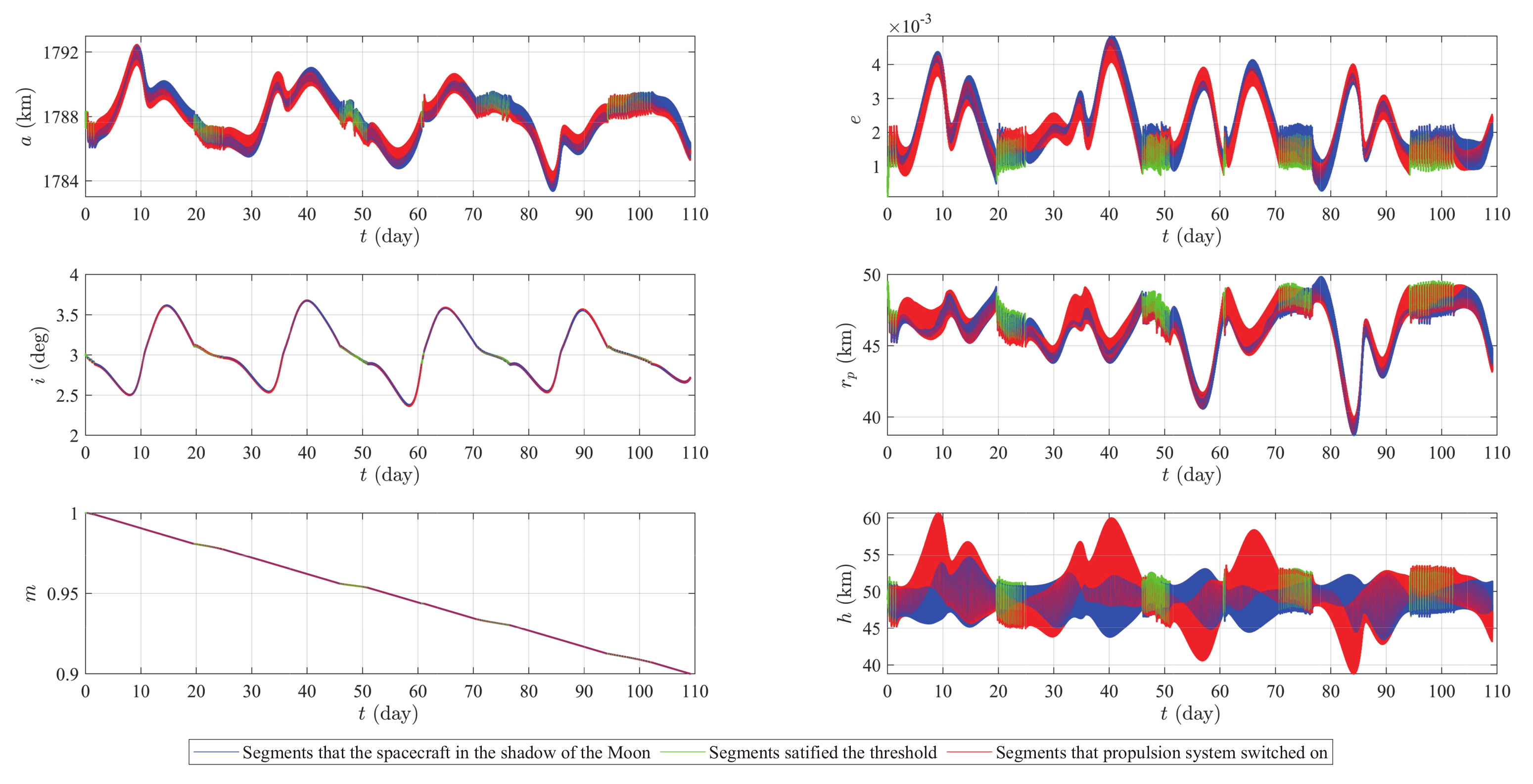
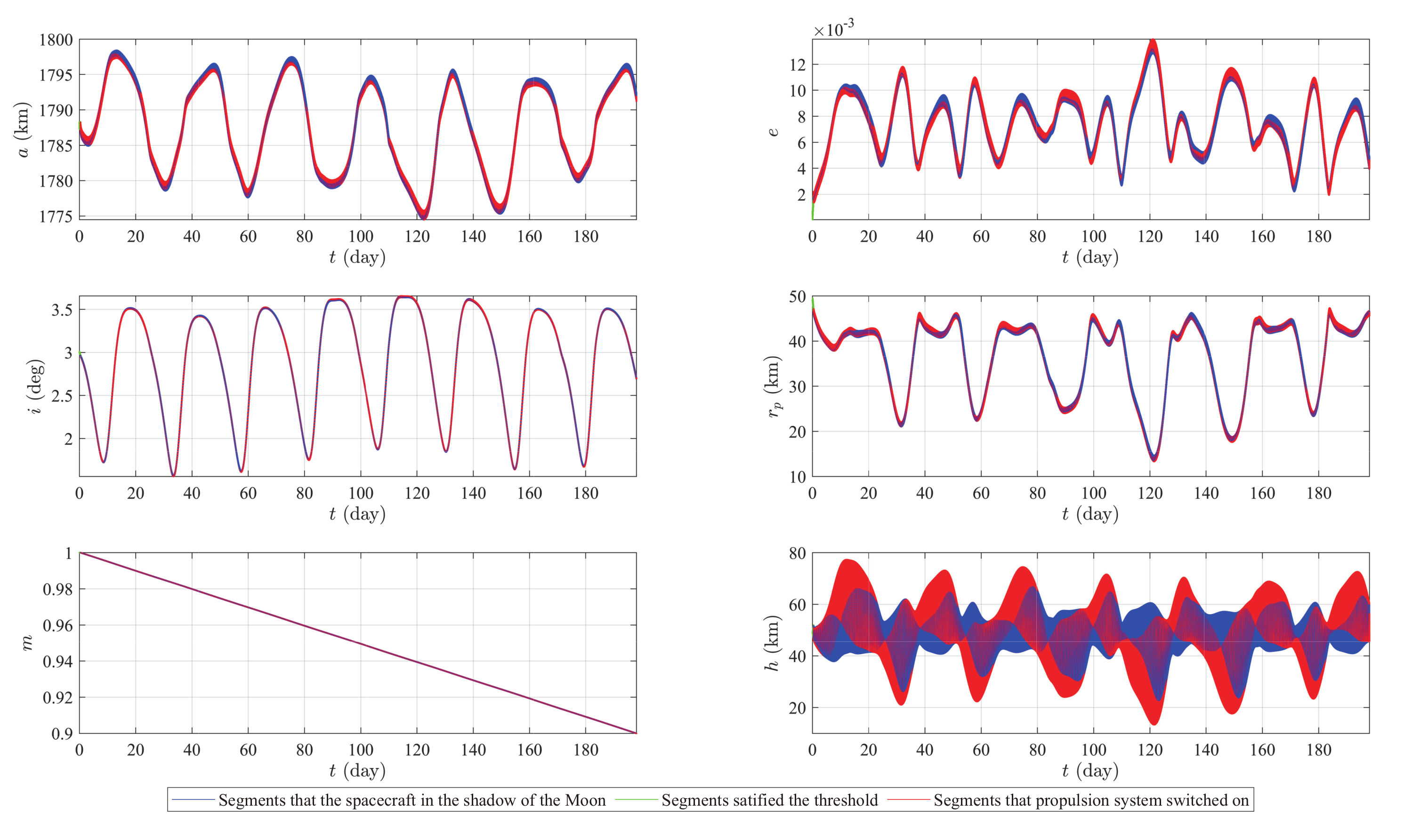
, the lifetime is 7.958 days. With the same initial conditions, the strategy proposed in the last section is applied. Orbit maintenance lasts 109.1725 days, until the fuel is depleted. The variation of orbit elements during the obit maintenance is shown
Figure 4.
The horizontal axis is time. The vertical axis in six figures are semi-major axis a, eccentricity e, inclination i, the periapsis , the remain mass of the spacecraft m and the current altitude h, respectively. The three colors represent the different statuses of the spacecraft. The red segments represent the status that the low-thrust propulsion system is switch-on for adjusting the orbit to the target orbit. The blue segments mean that the spacecraft in the shadow of the Moon, the low-thrust propulsion system is off. The green segments are for the status that the spacecraft does not exceed , the propulsion system does not need to be switched on.
Due to the altitude of the target orbit is very low, keeping the eccentricity extremely small is a significant problem. Comparing the second and last graphs in
Figure 4, the undulations in altitude correspond to the undulations in eccentricity. During maintenance, the proportion of time that eccentricity is smaller than
is over
; correspondingly, the proportion of the current altitude between 42 km and 58 km is
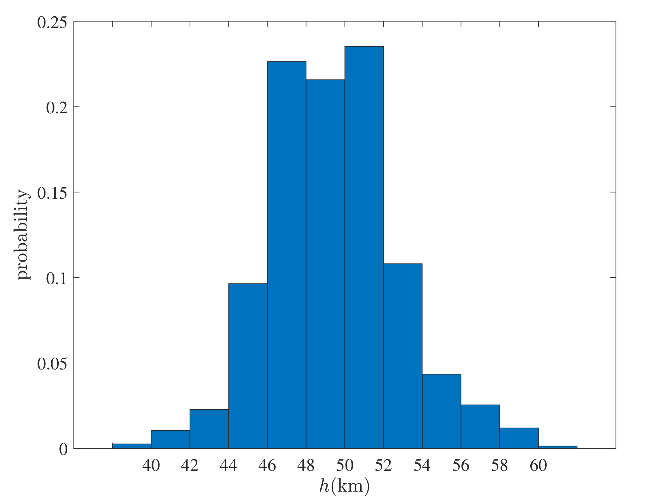
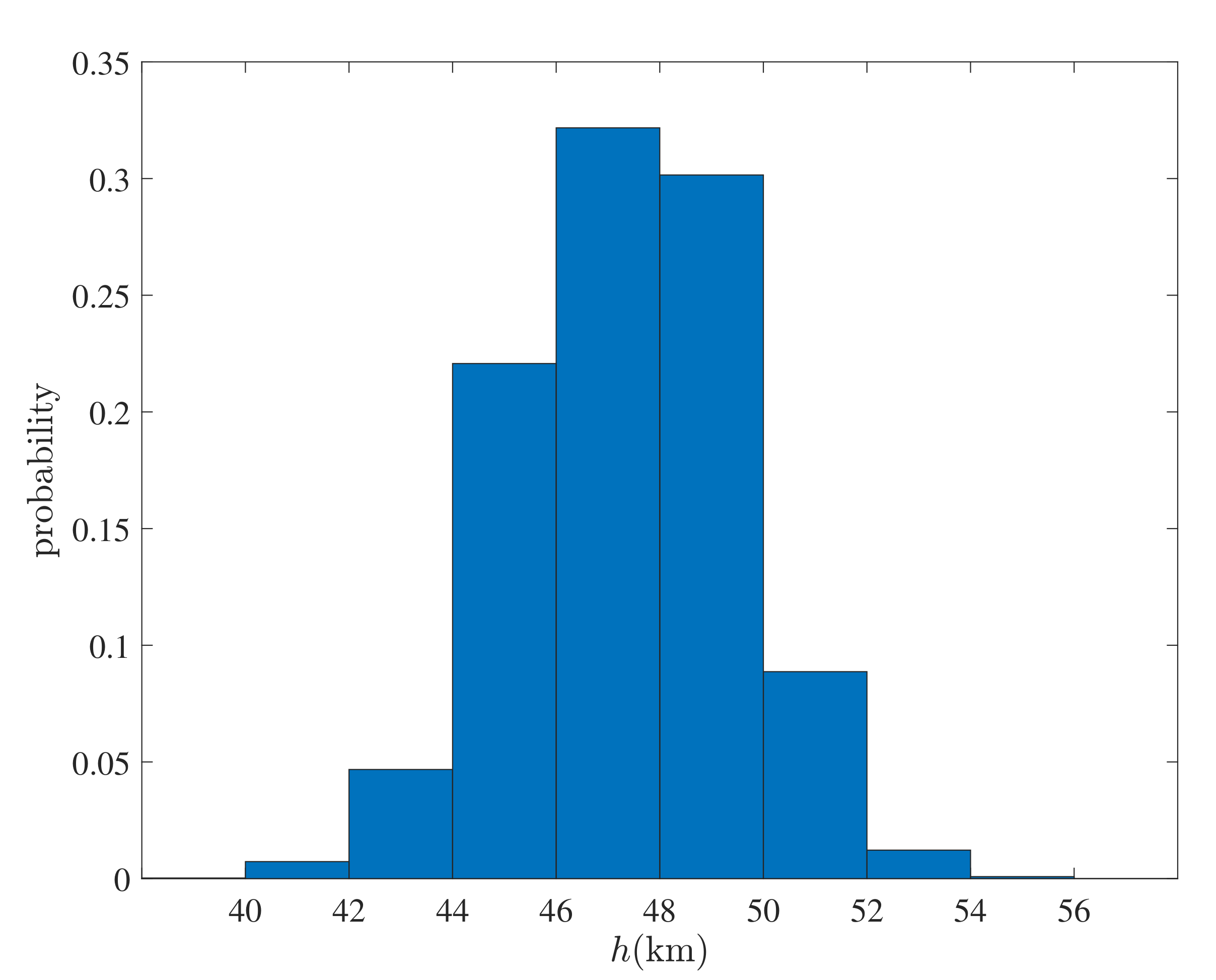
. The distribution of the altitude is shown in
Figure 5.
The x-axis represents the section of altitude, while the y-axis shows the proportion of each altitude section. The first bin on the left represents the proportion of the altitude lower than 40 km, the first bin on the right shows the proportion of the altitude higher than 60 km. The summation of these two proportions is less than
. The altitude of the spacecraft is mainly concentrated within the range from 46 km to 52 km. The inclination of the orbit is kept in
around the target inclination. The orbit is maintained in a relatively small neighborhood of the target orbit which means the problem of altitude divergence appeared in [
19] has been solved. Therefore, the orbit maintenance strategy is fairly good enough in lifetime extension for ultra low-altitude Lunar spacecraft.
As a controlled trial of the thrust magnitude, a numerical simulation with only the magnitude of the thrust changed, to
, was carried out. As shown in
Figure 6, the amplitude of the semi-major axis, eccentricity, inclination, periapsis, and altitude are smaller than those maintained by
. The altitude,
h, satisfies
over the whole maintenance duration. With a more powerful propulsion system, the transfer process from the current orbit to the target orbit is more efficient thanks to the reduction of the influence of the Moon’s shadow. However, the whole lifetime maintained by
is 95.7399 days, which is shorter than the duration maintained by
. This phenomenon is consistent with the last equation in Equation (
4), i.e., the mass-flow rate equation. During the whole maintenance period with
, the Lunar spacecraft is kept in the range of
, which is almost equal to that of
in the same range. However, the more powerful low-thrust propulsion system needs more electric power produced by larger solar-cell panels. With the same launch capability, the model with larger solar-cell panels is able to carry less scientific instruments and/or fuel.
Accordingly, the orbit maintenance with
is also proceeded. Due to the magnitude of thrust reduced, the performance of orbit maintenance is degradative.
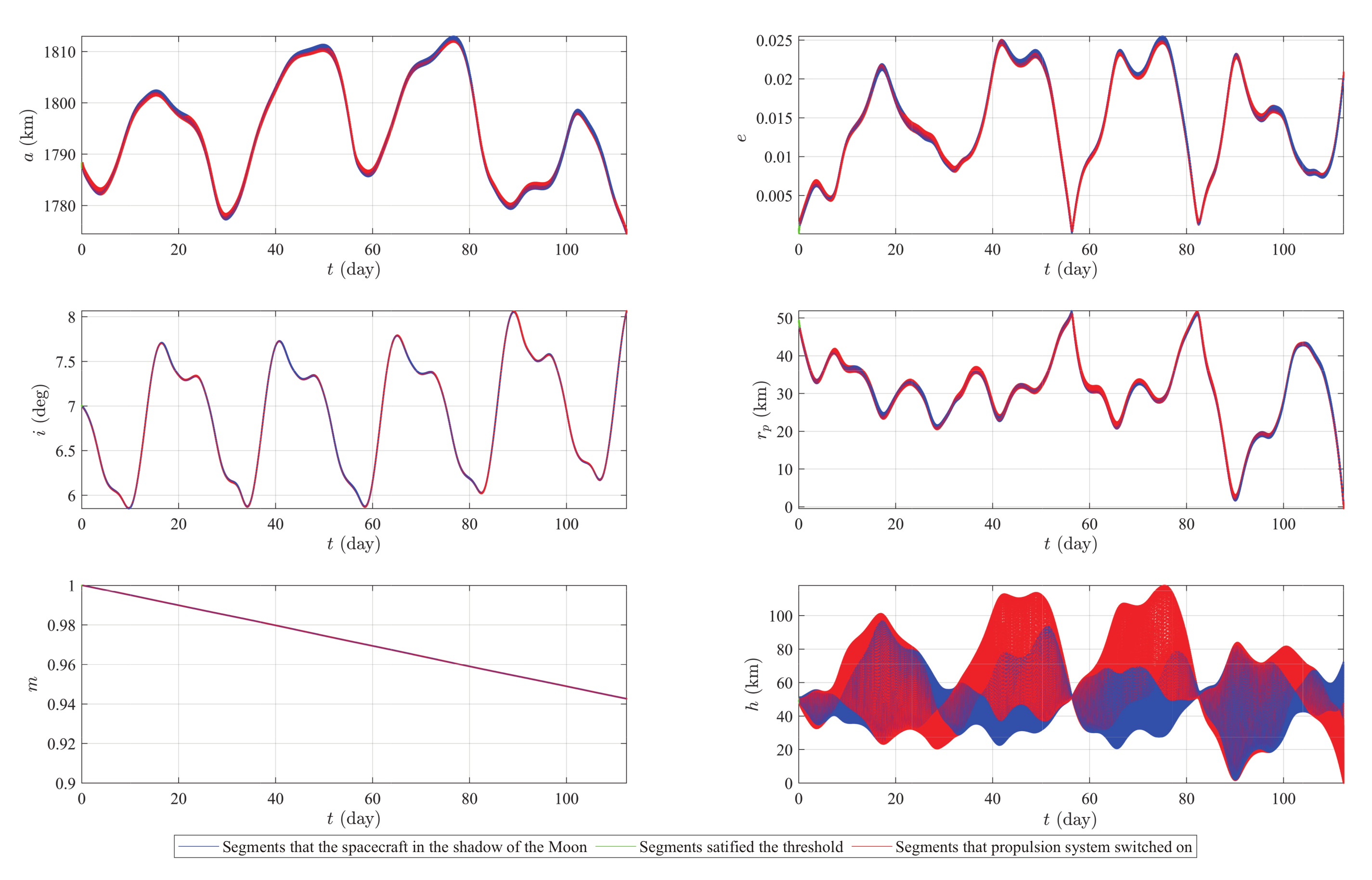
Figure 7 shows the results of orbit maintenance with thrust
in the conditions of RAAN
and inclination
. Compared to the maintenance with
and
, although the lifetime maintained by
reaches 198.0309 days, the amplitude of the orbit elements is comparatively large. The maximum height is 77.281 km and the minimum is 13.3543 km. As the figure shows, there are almost no green segments, which means that the propulsion system keeps working as long as the spacecraft is not in the shadow of the Moon. For more unstable orbits,
may not able to prevent collision.
Figure 8 shows the process of orbit maintenance with
in the conditions of RAAN
and inclination
. With smaller magnitude of thrust, the amplitudes of orbit elements are larger than the former simulations. The collision between the Moon surface and the spacecraft is postponed from 15.518 days to 112.87 days with fuel left.
According to the simulation results above, the orbit maintenance strategy proposed in this paper is generally effective. The magnitude of the thrust observably affects orbit maintenance. With large thrust, the fuel consumption of the spacecraft is fast, the lifetime can be extended significantly, and the orbit is maintained within quite a small neighborhood of the target orbit. With small thrust, the lifetime can be extended from several days to more than a hundred days. For orbits in the stable area, small thrust can avoid collision and the lifetime can be extended longer than is possible with larger thrust. For the unstable area, however, a large amount of thrust is necessary. The magnitude of thrust should be determined by experiment based on the specific requirements of the mission.
4.2. Initial Conditions and Fuel Ratio
Orbit maintenance varying with the initial conditions of orbit is analyzed in this subsection. As the contour of spacecraft lifetime without orbit maintenance shows, the initial conditions influence spacecraft lifetime. There are stable areas where spacecraft can avoid collision with the surface over a fairly long time. Several major perturbations in these areas are partly neutralized by each other. Therefore, the duration of orbit maintenance with these initial conditions could be even longer.
As shown in
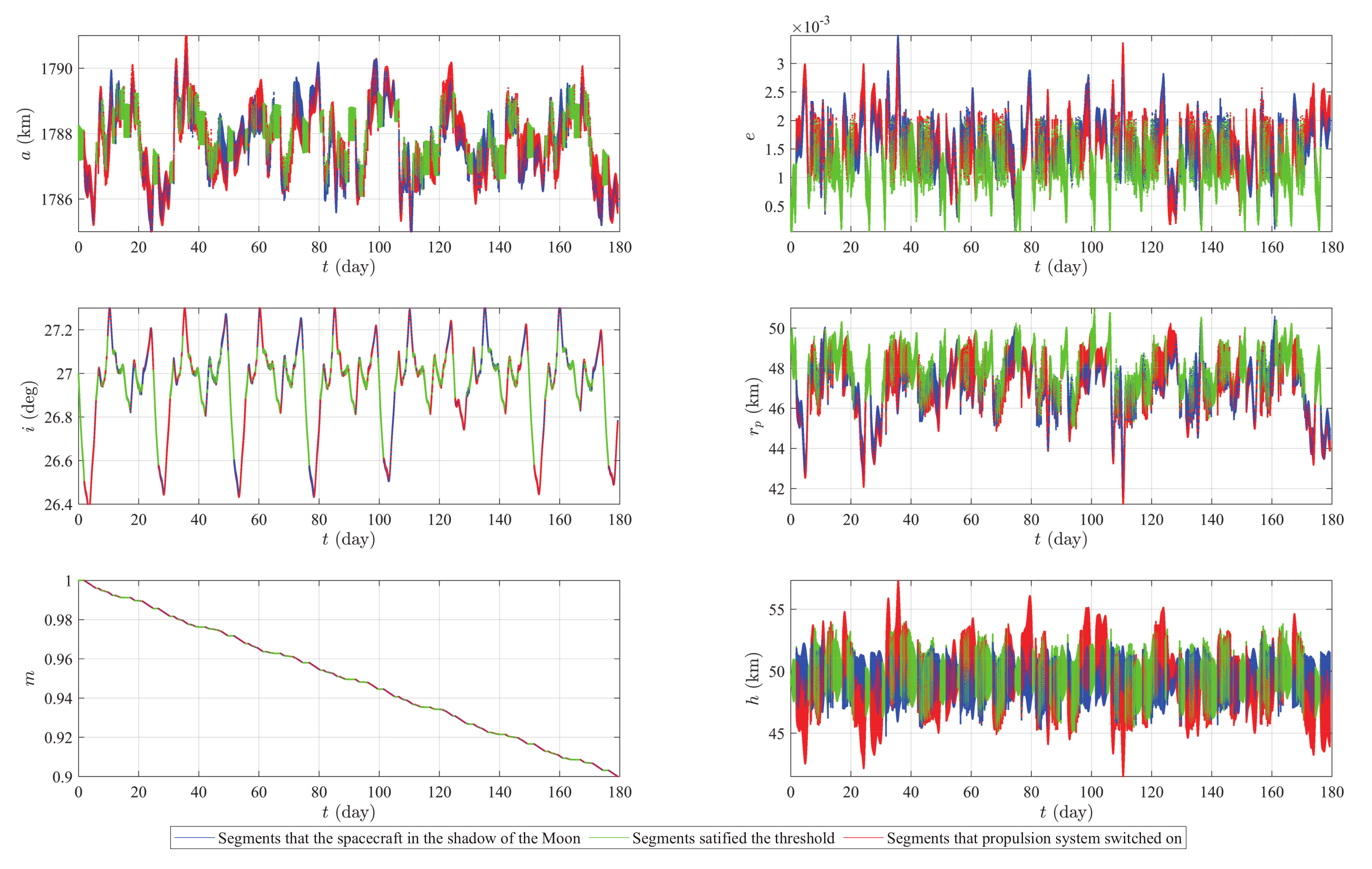
Figure 9, the initial conditions are
,
and thrust
. The duration of orbit maintenance reaches a length of 179.4 days, which is much longer than is the case with the initial conditions,
,
. The green segments represent where the spacecraft satisfies the required thresholds for the propulsion system to be in switch-off mode. Because the orbits with these initial conditions are more stable, the proportion of green segments is evidently enlarged.
Figure 10 shows the distribution of altitude,
h, during orbit maintenance. Compared with the simulated conditions of
,
, the altitude is concentrated more in the range from
to
. The proportion of altitude in this range is
. The proportion in the range between
and
increases to
. Therefore, spacecraft in the stable area can be maintained for a longer time, and the amplitudes of orbit elements are smaller.
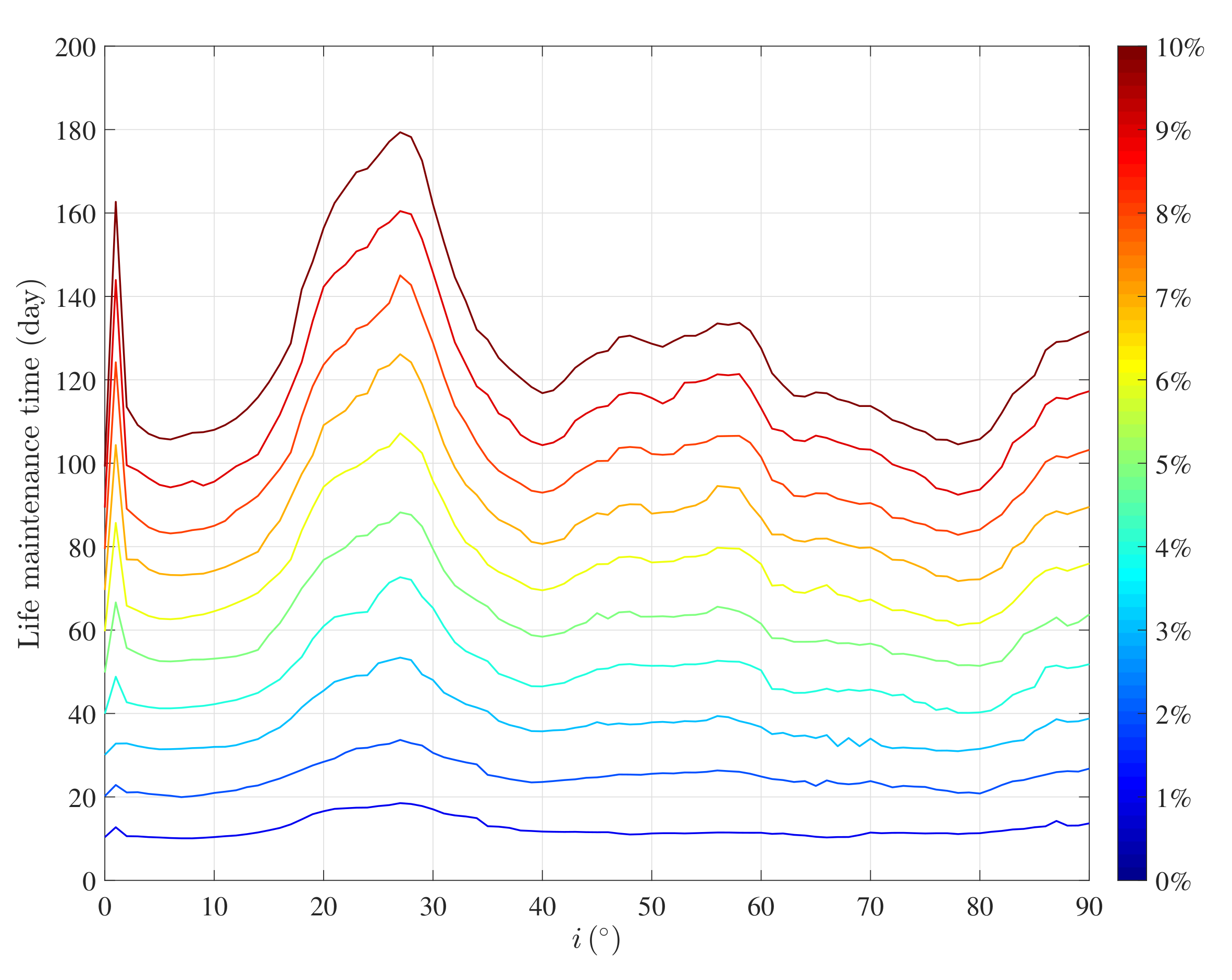
Due to differences in degree of stability, the effects of orbit maintenance in different inclinations are diverse. As shown in
Figure 11, life maintenance time varying with initial inclination is exhibited with
and
.
The horizontal axis is the initial inclination of the Lunar spacecraft, and the step of scanning the inclination is
. The vertical axis represents the life maintenance time. The different colors of solid lines indicate different ratios of fuel consumption. The index of the fuel ratio can be found in the color bar on the right side. As the color bar illustrates, the blue line shows the tendency of orbit maintenance days versus initial inclination with
fuel, while the red line shows the same situation with
fuel. With the same initial conditions, the lifetime can be maintained longer with more fuel. Local maximum values in the tendency of spacecraft lifetime vary with the inclination. The lifetime can be maintained longer when the initial inclination is
,
,
,
or
. These values of the initial inclination are in the neighborhood of frozen orbit inclination; the orbits in these area are more stable, which corresponds with the results in
Figure 9. Based on the results in
Figure 11, the degree of stability in these frozen orbits is different. Although spacecraft in these orbits may initially avoid collision, orbit maintenance is needed to keep the orbit within an appropriate range.
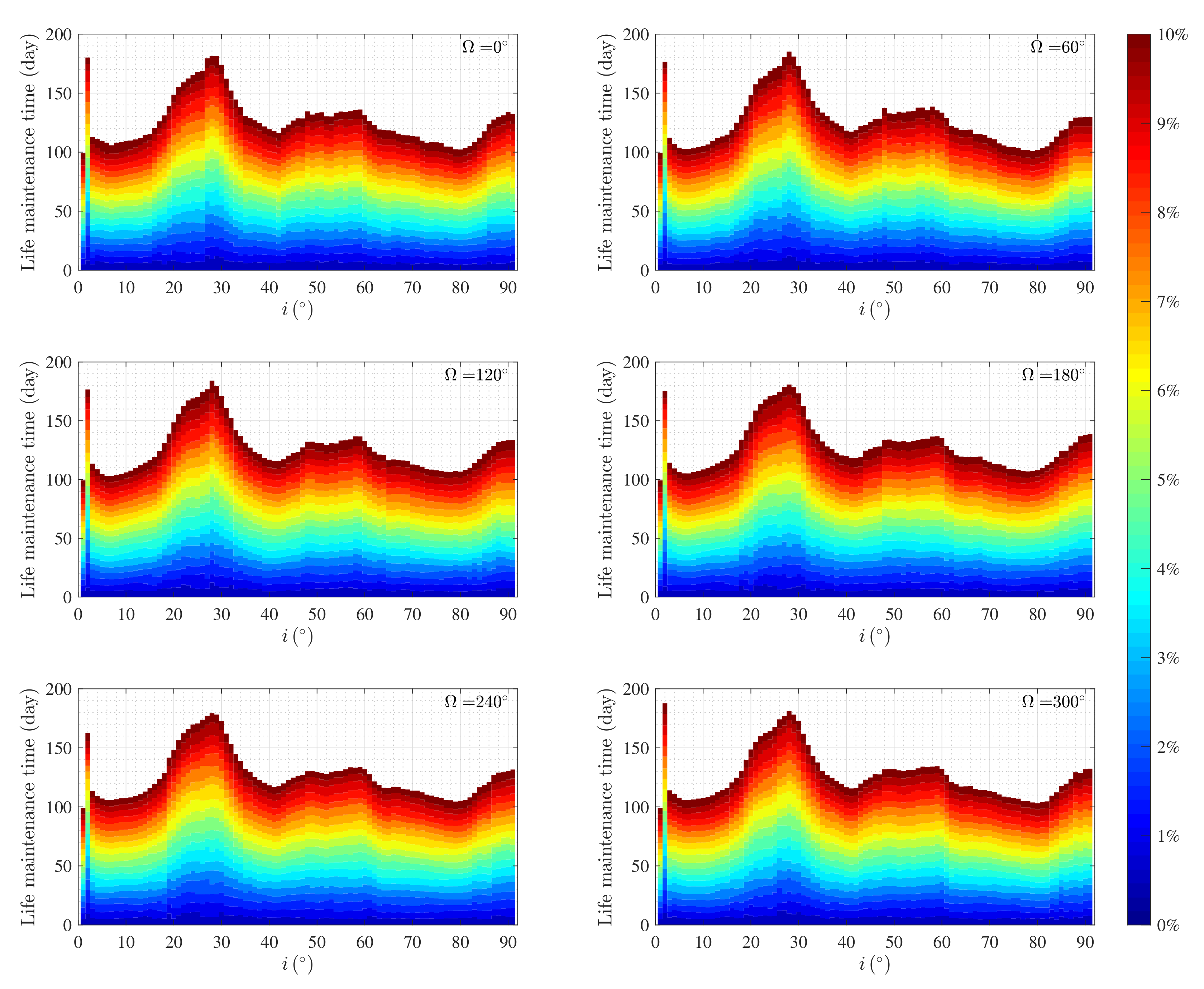
Figure 12 shows the influence of different initial RAAN on the life maintenance time. The six pictures represent
,
,
,
,
and
, respectively. The horizontal axis is initial inclination of the Lunar spacecraft and the vertical axis is the life maintenance time. The colorbar on the right side is the index of fuel ratio of the spacecraft which is shared by all the six pictures. In each figure, the lifetime extension result can be addressed with specific RAAN, inclination and fuel ratio.
Unlike the lifetime without orbit maintenance shown in
Figure 2, the difference in lifetime caused by different initial RAAN is slight. There is a similarity in the tendency of lifetime maintained versus initial inclination. The local maximum values and the initial conditions they correspond to are summarized in
Table 3. The first column is different initial RAAN, the second column is the inclination which maximize lifetime maintenance time and the third column is the local maximum values of lifetime maintenance time.
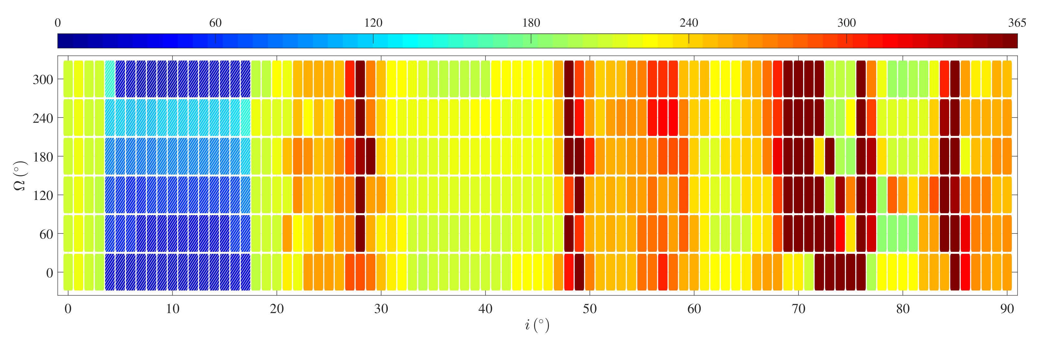
After fuel is depleted, the orbit of spacecraft evolves in the domination of Moon gravity, the spacecraft probably fall on the surface of the Moon under the influence of the non-sphere perturbation.
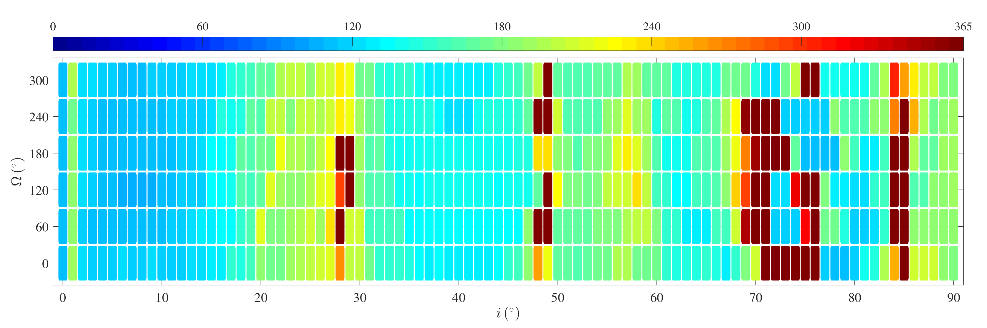
The lifetime from the beginning of orbit maintenance to the collision with
is shown in
Figure 13. The horizontal axis represents initial inclination and the vertical axis is for initial RAAN. Observing the figure along the horizontal direction, the figure shows the lifetime varies with initial inclination. Different horizontal bars exhibit the situation with different initial RAAN, the six bars are for
,
,
,
,
and
, respectively. The position of the rectangles represent the initial conditions of the simulations. The color represents the spacecraft lifetime and the lifetime exceeding one year is donated as 365 days. The colorbar on the top illustrates the correspondence between lifetime and color. The rectangles with pattern of oblique lines mean the collision happens before fuel is used up in their initial conditions. As the figure shown, the rectangles with pattern concentrates in the area of inclination between
and
. Although the collision is not avoided, the lifetime still is extended to several dozens days. For the orbits with inclination from
to
, the lifetime is generally extended to the range between 206 days and 230 days. The range of stable area near the frozen orbits is also extended, the lifetime of orbit in these areas is nearly 300 days. The quantity of orbit with lifetime more than 365 days increases evidently.
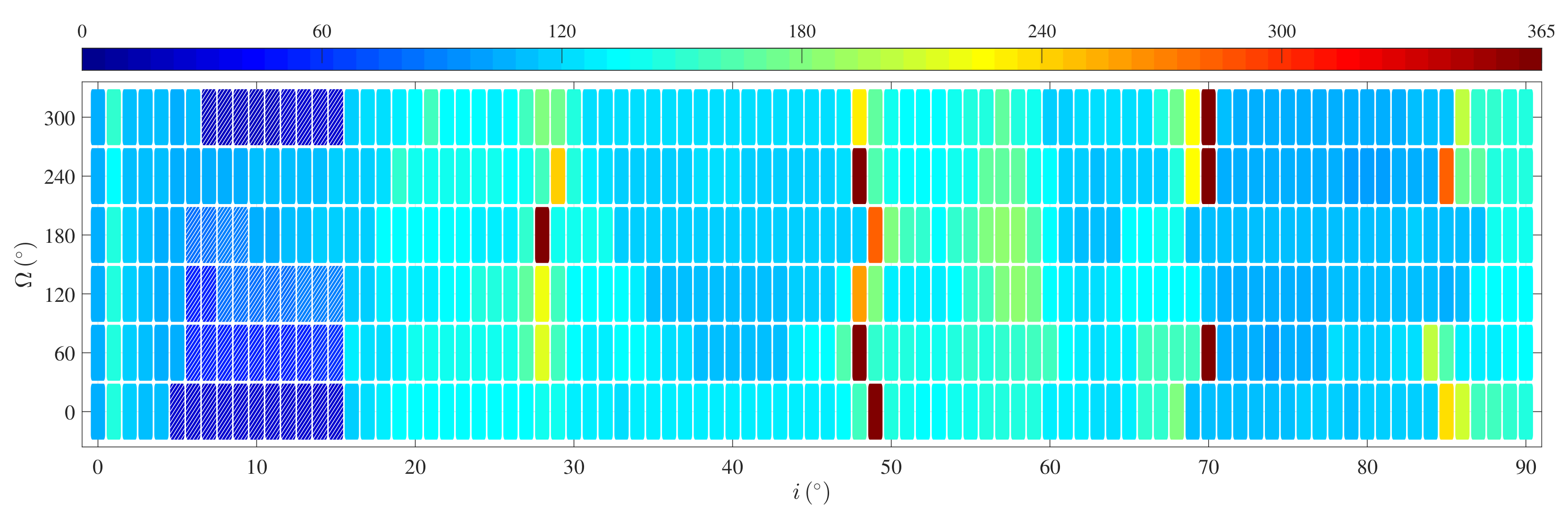
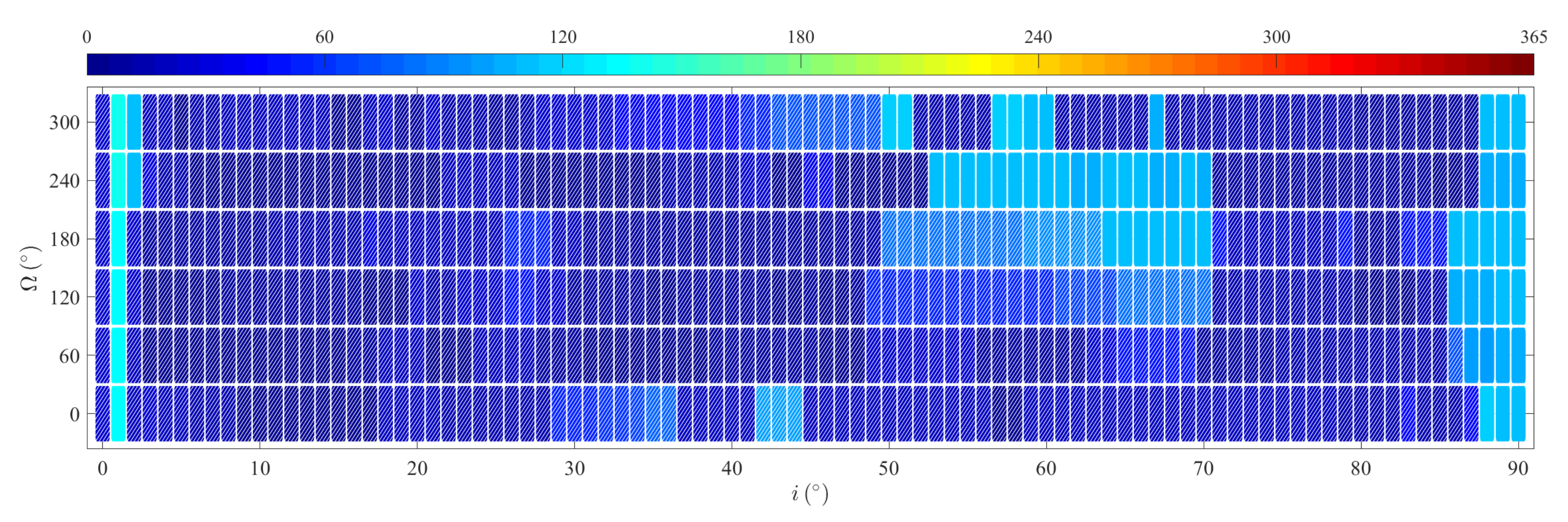
To eliminate the area where collision occurs before the fuel is fully used up, numerical simulations with
were carried out.
Figure 14 shows the lifetime from the beginning of orbit maintenance to collision maintained by
.
The deploy of axes and colorbar is the same as the one in
Figure 13. As the figure shown, the lifetime of orbit in low inclinations is extend further.The meaning of the axes and color bar is the same as in
Figure 13. As the figure shows, the lifetime of orbits in low inclinations is extended further. The lifetime reaches one hundred days, which is adequate for a Lunar mission. The results show that the strategy proposed in this paper extends the feasible region for ultra low-altitude Lunar spacecraft. It is achievable to design low-inclination orbiters for the mission of continuously observing low-latitude areas. From a global perspective, collision can be avoided globally as long as the fuel is not depleted. However, in comparison with
, the increased thrust shortens the orbit maintenance time for the situations that can be maintained by
originally. Therefore, the choice of magnitude of thrust should be adapted to the initial inclination of the target orbit.
4.3. Altitude
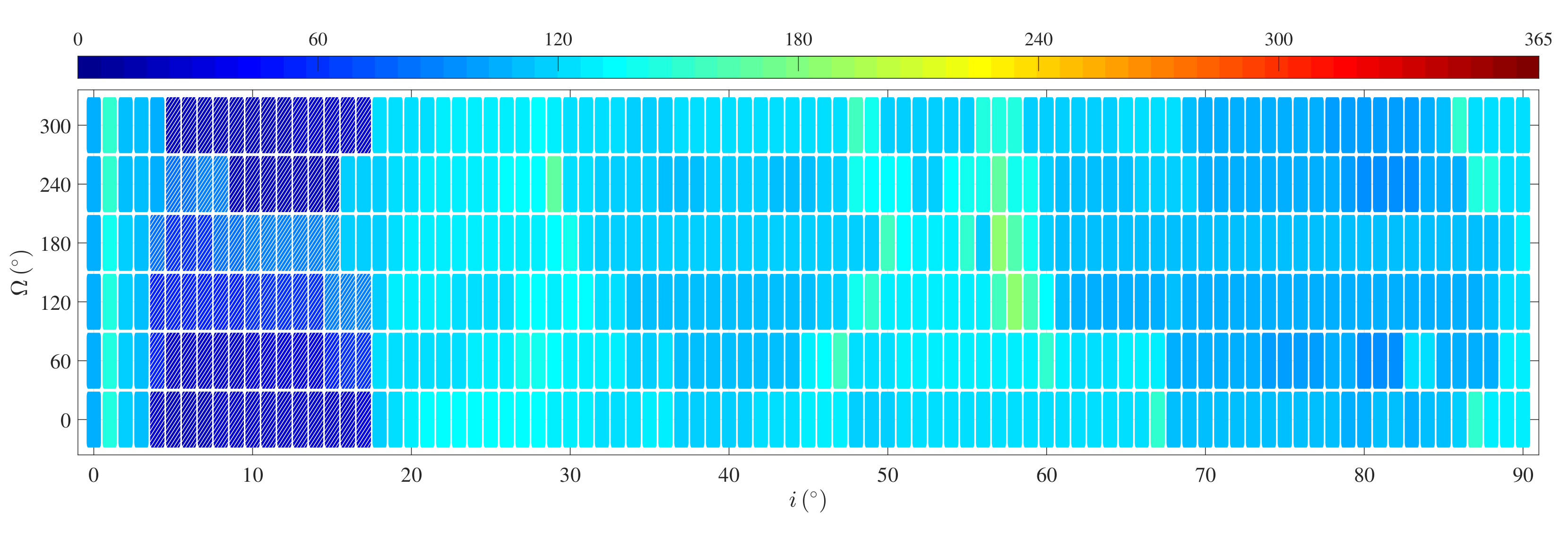
In this subsection, the results of the lifetime extension with different initial altitude are shown. With the magnitude of the thrust , the lifetime as counted from the beginning of orbit maintenance to collision is compared in the near-circular orbits with different altitudes. Different initial inclination and RAAN are taken into account as well.
As shown in
Figure 15, the lifetime of near-circular orbits with about 40 km-altitude is maintained with
. The initial semi-major axis is
and the eccentricity is
. Different initial inclination and RAAN as variables are displayed in the horizontal axis and the vertical axis, respectively. In order to conveniently compare lifetime with a 50 km-altitude, the range of color bars in this subsection is the same as in
Figure 14. In the 40 km-altitude orbit, the magnitude of thrust
cannot prevent collision all of the time. In the low-inclination area, there are rectangles with a pattern of oblique lines, which means that collision occurs with fuel left over. In addition, there are situations where the lifetime can be extended to over a year. Collision can be avoided in most situations, and the lifetime is between 120 days and 180 days, which is shorter than the lifetime of 50 km-altitude orbits generally.
With the other conditions unchanged,
Figure 16 shows the lifetime extension when
. With no initial conditions, the lifetime can be extended more than a year. With the initial conditions enumerated in the figure, the longest lifetime is
days. The extended lifetime is shortened generally, and the range of situations in which collision occurs before fuel runs out increases.
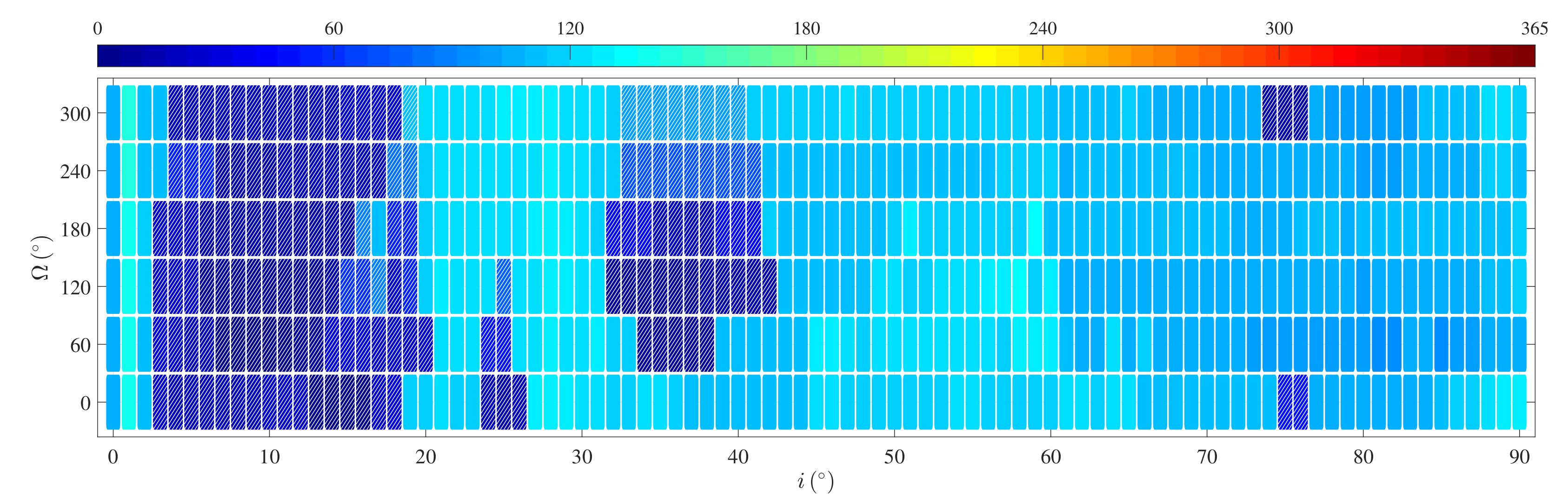
As shown in
Figure 17, the quantity of collision situations increases further with
. Most orbits in the low-inclination area can not avoid the collision. Besides, the collisions with fuel left are also happens in the higher inclination area. The lifetime generally shrinks down to shorter than 150 days. Except the low-inclination situations, the collisions also happens in middle-inclination (
) orbit and high-inclination (
) orbit.
Adjusting the semi-major axis to
, i.e., a near-circular orbit of about 10 km-altitude, collision can be avoided in most cases with
. The lifetime extension results are shown in
Figure 18. In the area where collision is avoided,
-altitude detection can be realized with
. In the other area, detection ought to proceed at a higher altitude or be maintained with larger thrust.
5. Conclusions
By discretizing the process of low-thrust transfer, the near-optimal direction of low thrust in every step can be calculated. The orbit maintenance strategy proposed in this paper realizes orbit maintenance in ultra low-altitude Lunar orbit. Based on the proposed strategy, simulations of 50 km and lower altitude lunar orbits have been processed. The results of these simulations show that lifetime extension depends on many conditions. With the same inclination and RAAN, the magnitude of the low thrust dominates the length and effect of orbit maintenance. For spacecraft with the parameters in our simulations, cannot avoid collision if the inclination of the orbit is between and , and collision occurs before the fuel is fully used up. For orbits with lower or higher inclination, can extend the lifetime to over 200 days. For orbits in the neighborhood of the frozen orbits, the orbit maintenance time can last for about 300 days. With certain initial conditions, the lifetime can be more than a year. With , the unstable area in low inclinations can be globally eliminated and the orbit can be maintained in an appropriate range. Even though the inclination of the orbit is between and , the lifetime can be extended to over a hundred days. For orbits with other inclinations, the lifetime is extended from two or three dozen days to about 150 days. For spacecraft in the frozen orbits, this strategy both avoids collision and maintains the orbit in an appropriate range. With , the disturbance caused by low thrust switching off in the shadow of the Moon can be partly neutralized. However, a larger thrust consumes fuel faster, and the duration of orbit maintenance is shorter than with . As the results of our simulations show, for middle and high inclination orbits can avoid collision. With larger thrust, the undulation of orbit elements can be diminished. Accordingly, the lifetime maintained is shortened. For orbits in low inclinations, the lifetime can be extended with ; as for the altitude of the Lunar spacecraft, the lifetime shrinks as the altitude of the spacecraft decreases. With , , and , collision can be avoided with arbitrary initial inclination and RAAN. When the semi-major axis decreases, the stability of the orbit becomes weaker and a Lunar spacecraft with a low inclination falls first. For orbits within about 30 km-altitude, the lifetime is shorter than 186 days. The decreasing altitude expands the unstable area where collision occurs before the fuel is fully depleted. For orbit within about 10 km-altitude, collision can be avoided for only a few specific initial conditions, and the longest lifetime extension is about 142 days.
The strategy proposed in this paper extends the lifetime of ultra low-altitude Lunar spacecraft, realizes orbit maintenance of the Lunar orbiter at altitudes of about 50 km and lower, and expands the feasible inclination for ultra low-altitude Lunar orbiters. The global perspective in this paper can be utilized in the orbit design of future Lunar projects such as navigation, remote sensing and rescue platforms. This next step of this research would combine the transfer orbits in cislunar space to formulate a whole mission vision. With further development of Moon exploration, the capabilities of lifetime extension and orbit maintenance in ultra low-altitude Lunar orbit will be strengthened.


