
Event-Triggered Attitude-Tracking Control for a Cableless Non-Contact Close-Proximity Formation Satellite


Abstract
:1. Introduction
2. Problem Statement
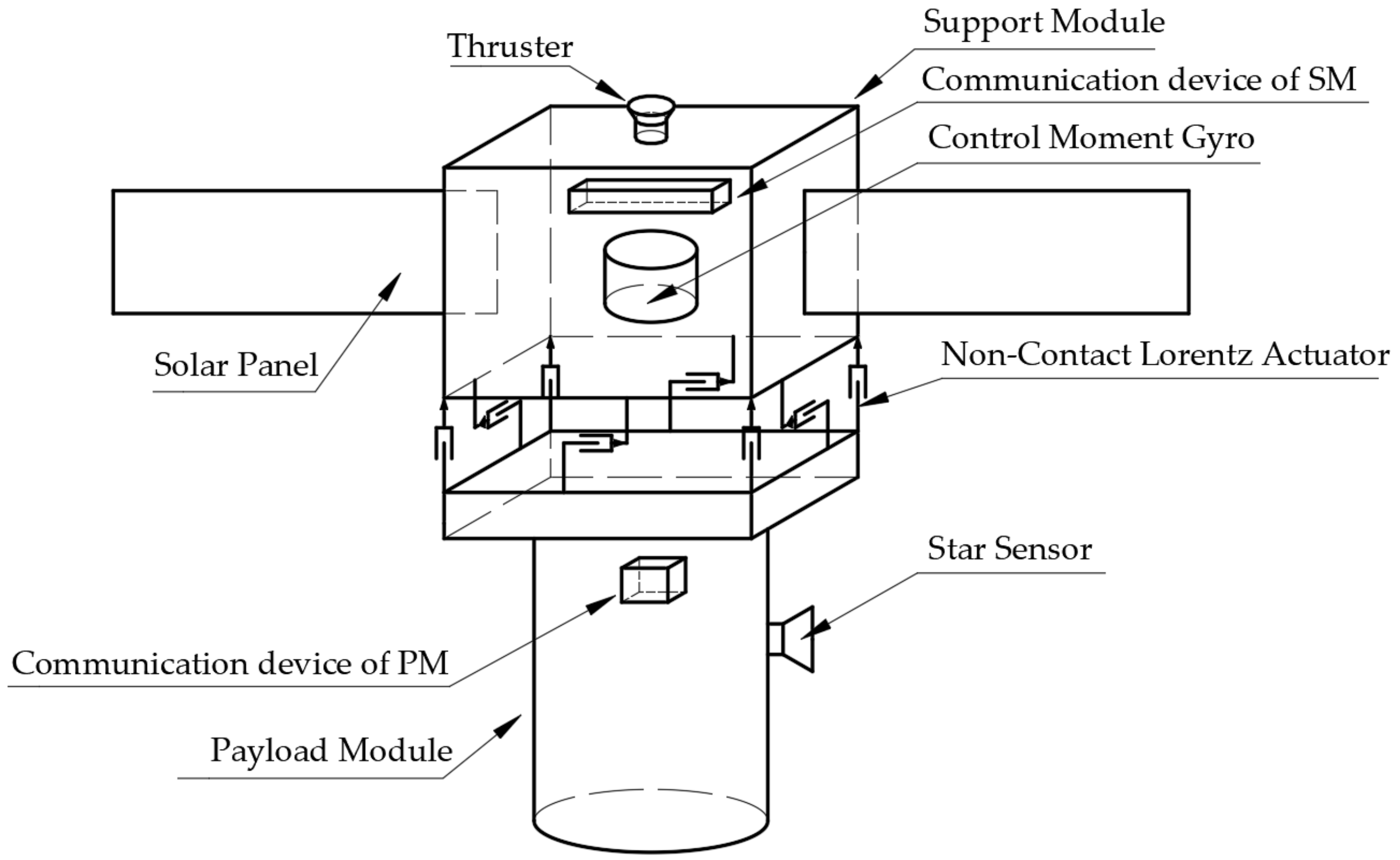
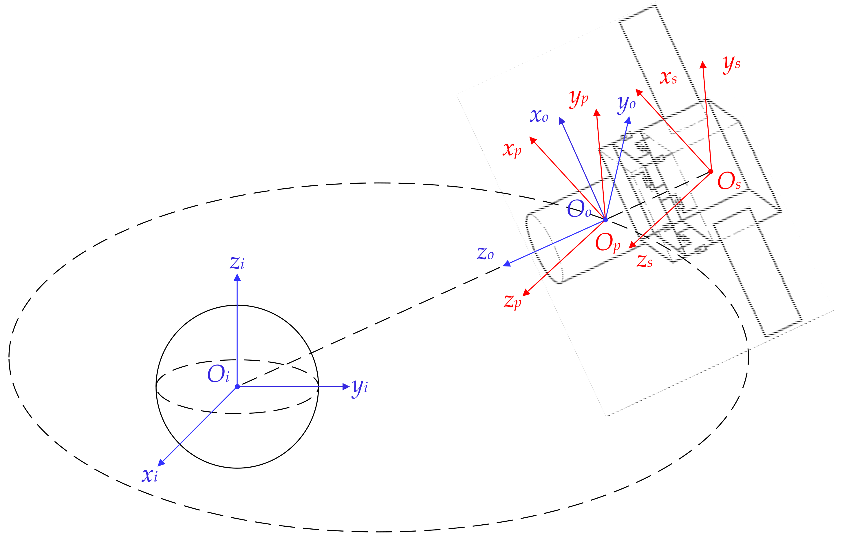
2.1. Hierarchical Architecture
2.2. Dynamics Modeling
2.3. Control Strategy Analysis
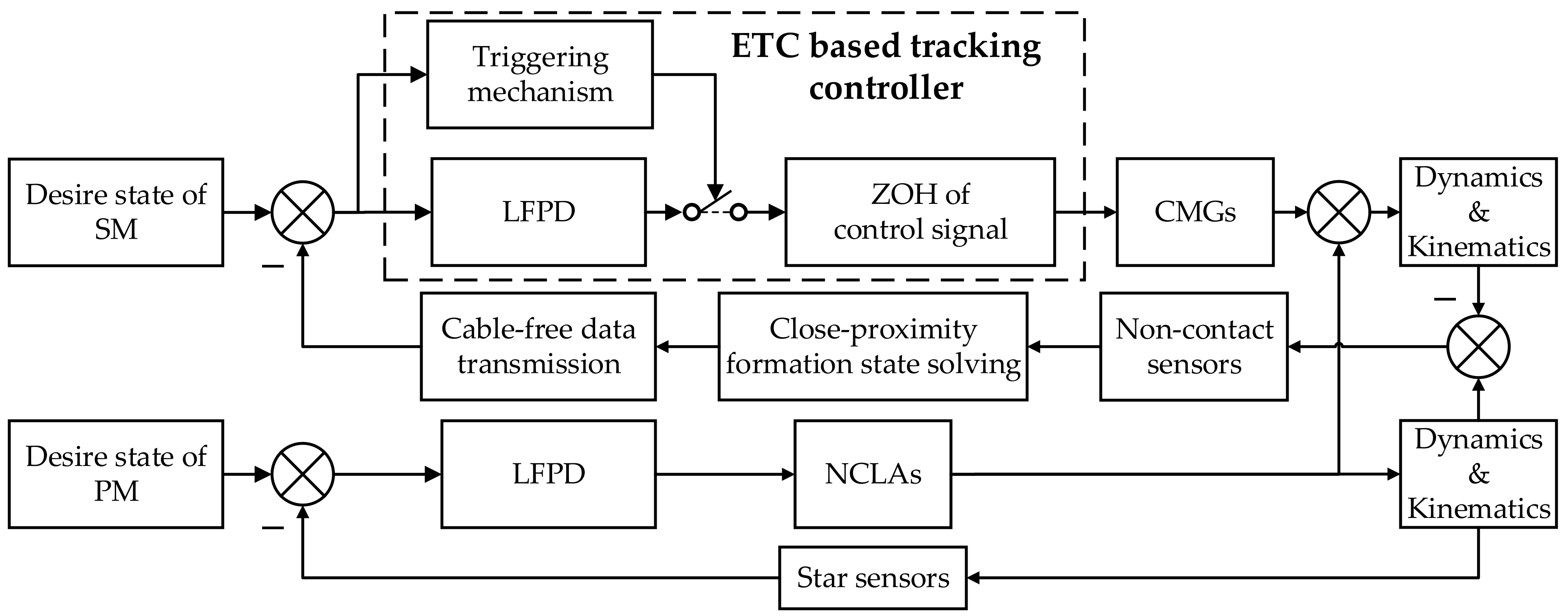
3. ETC Based Tracking Controller
3.1. Controller Design
3.2. Feasibility Analysis
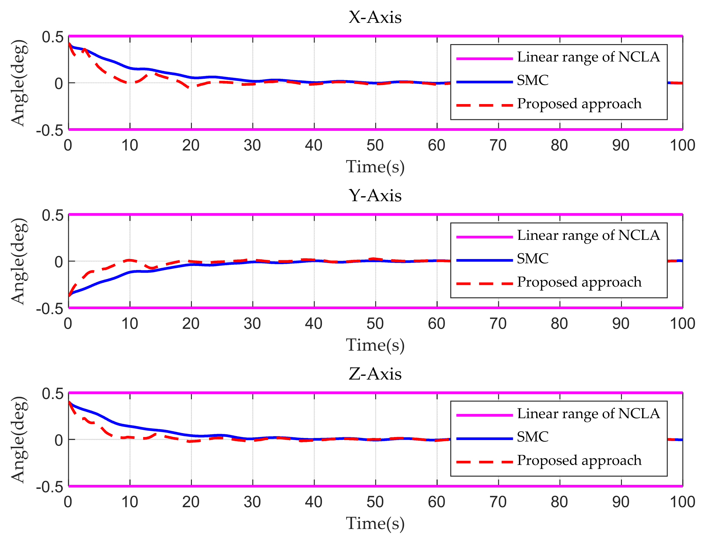
4. Numerical Simulations
5. Conclusions
Author Contributions
Funding
Institutional Review Board Statement
Informed Consent Statement
Conflicts of Interest
References
- Lian, X.B.; Zhang, J.X.; Yang, J.K.; Lu, Z.K.; Zhang, Y.; Song, Y.Q. The determination for ideal release point of test masses in drag-free satellites for the detection of gravitational waves. Adv. Space Res. 2021, 67, 824–833. [Google Scholar] [CrossRef]
- Li, Z.; Zheng, J.H. Orbit determination for a space-based gravitational wave observatory. Acta Astronaut. 2021, 185, 170–178. [Google Scholar] [CrossRef]
- Wahballah, W.A.; Eltohamy, F.; Bazan, T.M. Influence of Attitude Parameters on Image Quality of Very High-Resolution Satellite Telescopes. IEEE Trans. Aerosp. Electron. Syst. 2021, 57, 1177–1183. [Google Scholar] [CrossRef]
- Sanfedino, F.; Preda, V.; Pommier-Budinger, V.; Alazard, D.; Boquet, F.; Bennani, S. Robust active mirror control based on hybrid sensing for spacecraft line-of-sight stabilization. IEEE Trans. Control Syst. Technol. 2021, 29, 220–235. [Google Scholar] [CrossRef]
- Jiang, C.S.; Liu, Y.J.; Jiang, Y.; Li, H.N. Orbital Design and Control for Jupiter-Observation Spacecraft. Aerospace 2021, 8, 282. [Google Scholar] [CrossRef]
- Almazrouei, A.; Khan, A.; Almesmari, A.; Ahmed, B.; Ali, A.M.; Ali, A.; Alya, A. A Complete Mission Concept Design and Analysis of the Student-Led CubeSat Project: Light-1. Aerospace 2021, 8, 247. [Google Scholar] [CrossRef]
- Gonzales, M.; Pedreiro, N.; Brookes, K.; Roth, D.; Foster, B. Unprecedented vibration isolation demonstration using the disturbance-free payload concept. AIAA Guid. Navig. Control Conf. 2004, 6, 5247. [Google Scholar]
- Tajdaran, K.; Dewell, L.D.; Eason, E.V.; Bell, R.M.; Liu, K.C.; Bolcar, M.R.; Sacks, L.W.; Crooke, J.A.; Blaurock, C. Telescope line-of-sight slew control and agility with non-contact vibration isolation for the large ultraviolet/optical /infrared (LUVOIR) surveyor concept. SPIE Conf. 2017, 10698, 106983Y. [Google Scholar]
- Li, Q.; Liu, L.; Deng, Y.F.; Tang, S.; Zhao, Y.B. Twistor-based synchronous sliding mode control of spacecraft attitude and position. Chin. J. Aeronaut. 2018, 31, 1153–1164. [Google Scholar] [CrossRef]
- Liao, H.; Xie, J.J.; Li, S.; Tang, Z.X.; Xu, Y.; Zhao, Y.B. Stringent three-axis stability control for novel non-contact satellite using embedded second-order noise estimator. Adv. Space Res. 2021, 69, 1619–1630. [Google Scholar] [CrossRef]
- Rigatos, G.; Siano, P.; Selisteanu, D.; Precup, R.E. Nonlinear optimal control of oxygen and carbon dioxide levels in blood. Intell. Ind. Syst. 2017, 3, 61–75. [Google Scholar] [CrossRef]
- Chen, T.; Babanin, A.; MUḤAMMAD, A.; Bert, C.; Cyj, C. Modified Evolved Bat Algorithm of Fuzzy Optimal Control for Complex Nonlinear Systems. Rom. J. Inf. Sci. Tech. 2020, 23, T28–T40. [Google Scholar]
- Zamfirache, I.A.; Precup, R.E.; Roman, R.C.; Petriu, E.M. Reinforcement Learning-based control using Q-learning and gravitational search algorithm with experimental validation on a nonlinear servo system. Inf. Sci. 2022, 583, 99–120. [Google Scholar] [CrossRef]
- Zhou, J.; Liu, L.; Wang, Z.; Lil, J.; Liao, H.; Deng, Y. On pointing accuracy and pointing stability of disturbance-free payload using umbilical connection. In Proceedings of the 37th Chinese Control Conference, Wuhan, China, 25–27 July 2018; pp. 1591–1596. [Google Scholar]
- Yang, H.J.; Liu, L.; Liu, Y.; Li, X.G. Modeling and Micro-vibration Control of Flexible Cable for Disturbance-Free Payload Spacecraft. Microgravity Sci. Technol. 2021, 33, 1–16. [Google Scholar] [CrossRef]
- Wu, C.; Kong, X.R.; Liu, Y.F.; Chen, Z.P. Coupling characteristics analysis for the disturbance free payload spacecraft. Acta Astronaut. 2017, 138, 407–416. [Google Scholar] [CrossRef]
- Kong, Y.F.; Huang, H. Performance enhancement of disturbance-free payload with a novel design of architecture and control. Acta Astronaut. 2019, 159, 238–249. [Google Scholar] [CrossRef]
- Alto, P. System-Level Segmented Telescope Design Final Report. Available online: http://www.astrostrategictech.us/pdf/projectfiles/Reports/17-SLSTD17-0001_FR_LM_2019_04_Public.pdf (accessed on 4 February 2022).
- Song, K.; Ma, B.Q.; Yang, G.; Jiang, J.H.; Wei, R.Z.; Zhang, H.; Zhu, C.B. A rotation light weight wireless power transfer system for solar wing driving. IEEE Trans. Power Electron. 2018, 34, 8816–8830. [Google Scholar] [CrossRef]
- Ge, X.H.; Ahmad, I.; Han, Q.L.; Wang, J.; Zhang, X.M. Dynamic event-triggered scheduling and control for vehicle active suspension over controller area network. Mech. Syst. Signal Process. 2021, 152, 107481. [Google Scholar] [CrossRef]
- Li, S.; Li, Z.; Li, J.; Fernando, T.; Lu, H.H.; Wang, Q.L.; Liu, X.D. Application of event-triggered cubature Kalman filter for remote nonlinear state estimation in wireless sensor network. IEEE Trans. Ind. Electron. 2020, 68, 5133–5145. [Google Scholar] [CrossRef]
- Liu, W.X.; Geng, Y.H.; Wu, B.L.; Wang, D.W. Neural-network-based adaptive event-triggered control for spacecraft attitude tracking. IEEE Trans. Neural Netw. Learn. Syst. 2019, 31, 4015–4024. [Google Scholar] [CrossRef]
- Zhang, C.X.; Dai, M.Z.; Dong, P.; Leung, H.; Wang, J.H. Fault-tolerant attitude stabilization for spacecraft with low-frequency actuator updates: An integral-type event-triggered approach. IEEE Trans. Aerosp. Electron. Syst. 2020, 57, 729–737. [Google Scholar] [CrossRef]
- Zhang, P.P.; Liu, T.F.; Jiang, Z.P. Event-triggered stabilization of a class of nonlinear time-delay systems. IEEE Trans. Autom. Control. 2020, 66, 421–428. [Google Scholar] [CrossRef]
- Xu, S.D.; Wei, Z.T.; Huang, Z.; Wen, H.; Jin, D.P. Fuzzy-logic-based robust attitude control of networked spacecraft via event-triggered mechanism. IEEE Trans. Aerosp. Electron. Syst. 2020, 57, 206–226. [Google Scholar] [CrossRef]
- Zhang, C.X.; Dai, M.Z.; Wu, J.; Xiao, B.; Li, B.; Wang, M.J. Neural-networks and event-based fault-tolerant control for spacecraft attitude stabilization. Aerosp. Sci. Technol. 2021, 114, 106746. [Google Scholar] [CrossRef]
- Di, F.Q.; Li, A.J.; Guo, Y.; Xie, C.Q.; Wang, C.Q. Event-triggered sliding mode attitude coordinated control for spacecraft formation flying system with disturbances. Acta Astronaut. 2021, 188, 121–129. [Google Scholar] [CrossRef]
- Xing, L.; Zhang, J.Q.; Liu, C.; Zhang, X. Fuzzy-logic-based adaptive event-triggered sliding mode control for spacecraft attitude tracking. Aerosp. Sci. Technol. 2021, 108, 106394. [Google Scholar] [CrossRef]
- Chi, W.C.; Ma, H.; Wang, C.H.; Zhao, T.Y. Research on Control of Stewart Platform Integrating Small Attitude Maneuver and Vibration Isolation for High-Precision Payloads on Spacecraft. Aerospace 2021, 8, 333. [Google Scholar] [CrossRef]
- Papakonstantinou, C.; Lappas, V.; Kostopoulos, V. A Gimballed Control Moment Gyroscope Cluster Design for Spacecraft Attitude Control. Aerospace 2021, 8, 273. [Google Scholar] [CrossRef]
- Gaude, A.; Lappas, V. Design and Structural Analysis of a Control Moment Gyroscope (CMG) Actuator for CubeSats. Aerospace 2020, 7, 55. [Google Scholar] [CrossRef]
- Liao, H.; Xu, Y.F.; Zhu, Z.; Deng, Y.F.; Zhao, Y.B. A new design of drag-free and attitude control based on non-contact satellite. ISA Trans. 2019, 88, 62–72. [Google Scholar] [CrossRef]
- Lee, D. Fault-tolerant finite-time controller for attitude tracking of rigid spacecraft using intermediate quaternion. IEEE Trans. Aerosp. Electron. Syst. 2020, 57, 540–553. [Google Scholar] [CrossRef]
- Fu, J.B.; Liu, M.; Cao, X.B.; Ang, L. Robust neural-network-based quasi-sliding-mode control for spacecraft-attitude maneuvering with prescribed performance. Aerosp. Sci. Technol. 2021, 112, 106667. [Google Scholar] [CrossRef]


| Parameter | Value | |
|---|---|---|
| Simulation environment | Simulation system | Windows 10 20H2 |
| Simulation duration | 100 s | |
| Simulation step | 0.05 s | |
| Non-contact close-proximity formation satellite | Flying orbit | Dusk-dawn sun-synchronized orbitat an altitude of 400 km |
| Earth gravity model | TJGRACE02S | |
| Magnetic field model | IGRF 13 × 13 | |
| Atmospheric drag model | Exponential model | |
| Solar radiation pressure model | Photon radiation | |
| Inertia matrix of the PM | ||
| Inertia matrix of the SM | ||
| NCLA | Air-clearance range | ±0.9° |
| Linear range | ±0.5° | |
| Attitude state | qpo,p | [0.9998, 0.0132, −0.0086, 0.0104]T |
| ωpo,p | [0, −0.0635, 0]T deg/s | |
| qsp,s | [1, 0.0037, −0.0032, 0.0035]T | |
| ωsp,s | [0.0021, 0.0042, −0.0033]T deg/s | |
| Solar panel | Coupling matrix | |
| Damping coefficient matrix | ||
| Modal frequency diagonal matrix | ||
| External disturbance torques of the SM and PM | ||
| Parameter | Value | |
|---|---|---|
| SMC | 5 | |
| 0.95 | ||
| 3 | ||
| 0.95 | ||
| Proposed approach | 1.1 | |
| 58 | ||
| Kps | ||
| Kds | ||
| Kpp | ||
| Kdp | ||
| Indexes | δ | ε | NTI 1 | PRCT 2 |
|---|---|---|---|---|
| Case 1 | 1.10 | 58 | 196 | 90.4% |
| Case 2 | 0.8 | 58 | 208 | 89.6% |
| Case 3 | 0.8 | 50 | 232 | 88.4% |
| Indexes | SMC | Proposed Approach | |
|---|---|---|---|
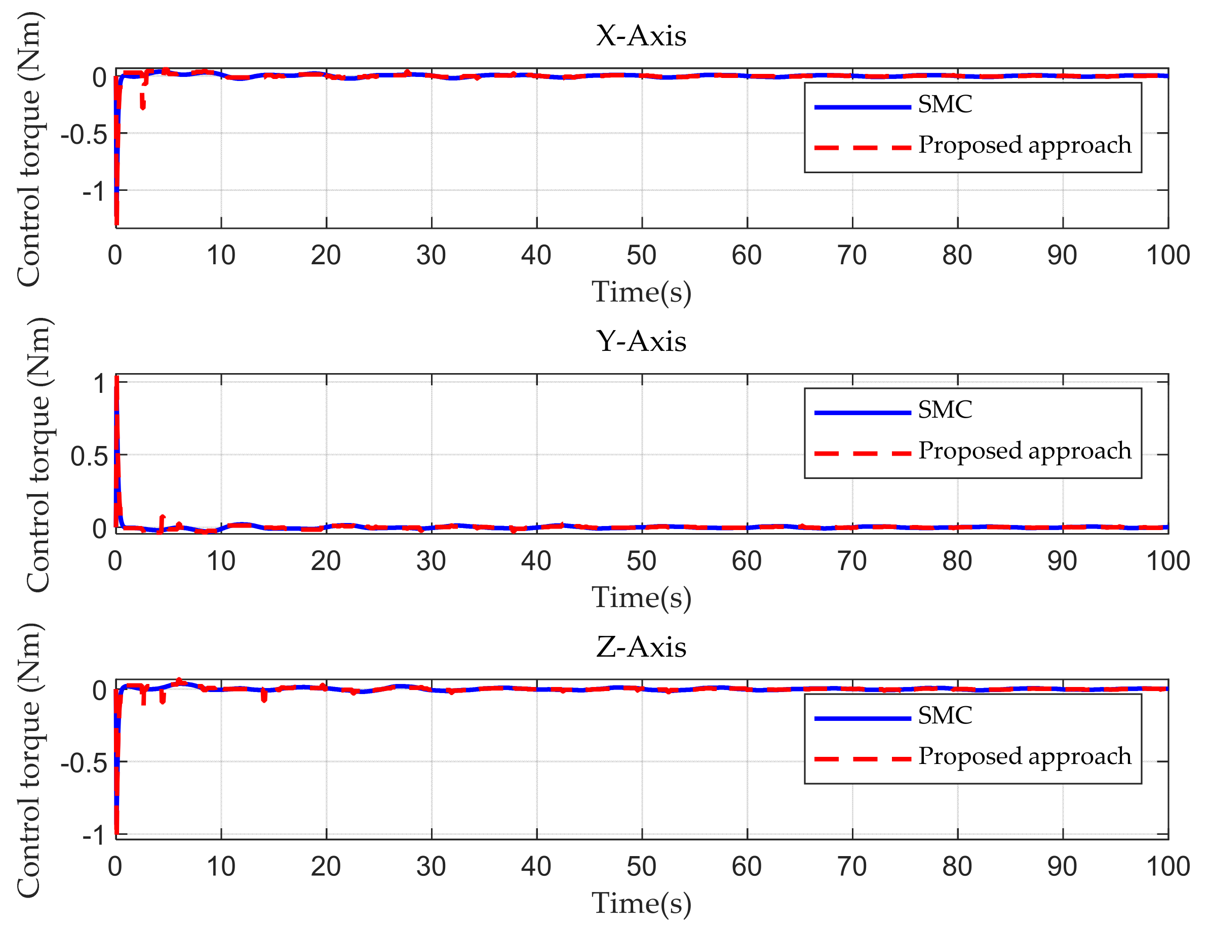
| Maintaining the linear range of the NCLA | Success | Success | |
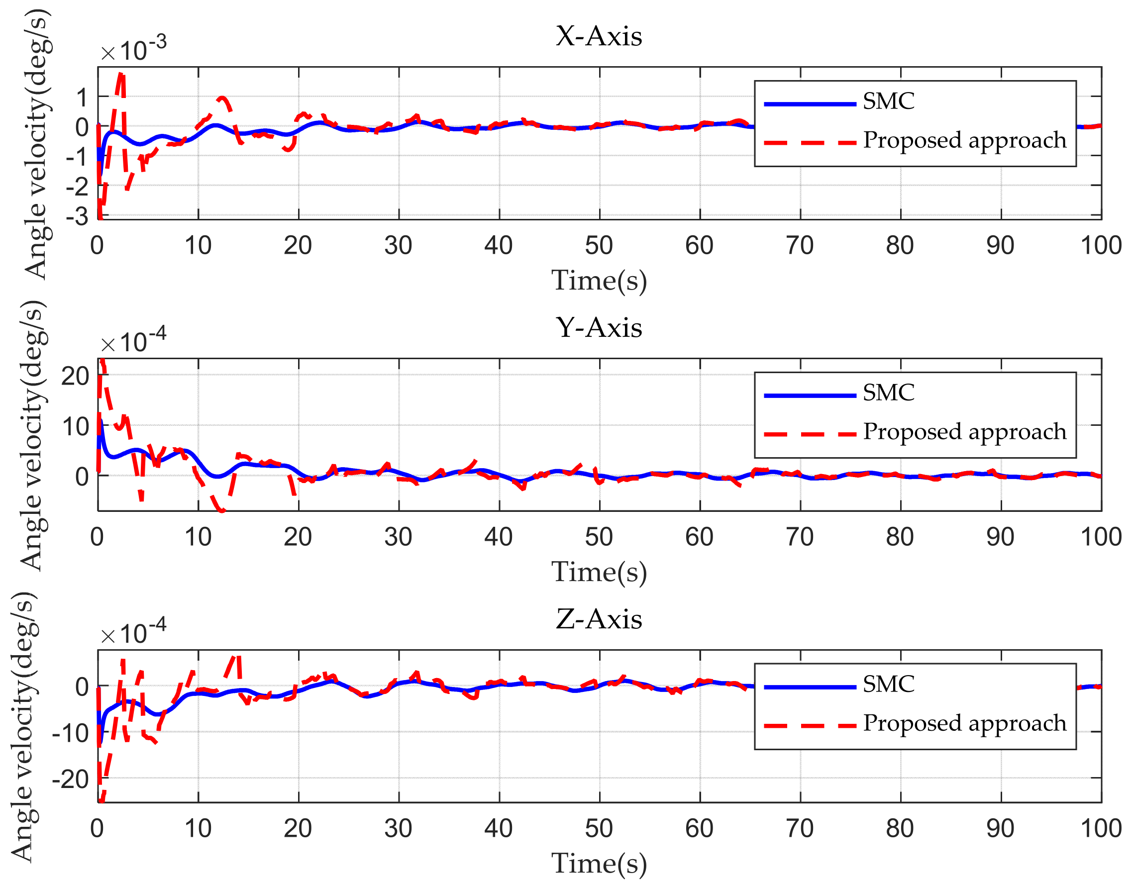
| Convergence rate of the SM | Attitude angle | 29 s | 22 s (slightly oscillating) |
| Angular velocity | 23 s | 25 s (clearly oscillating) | |
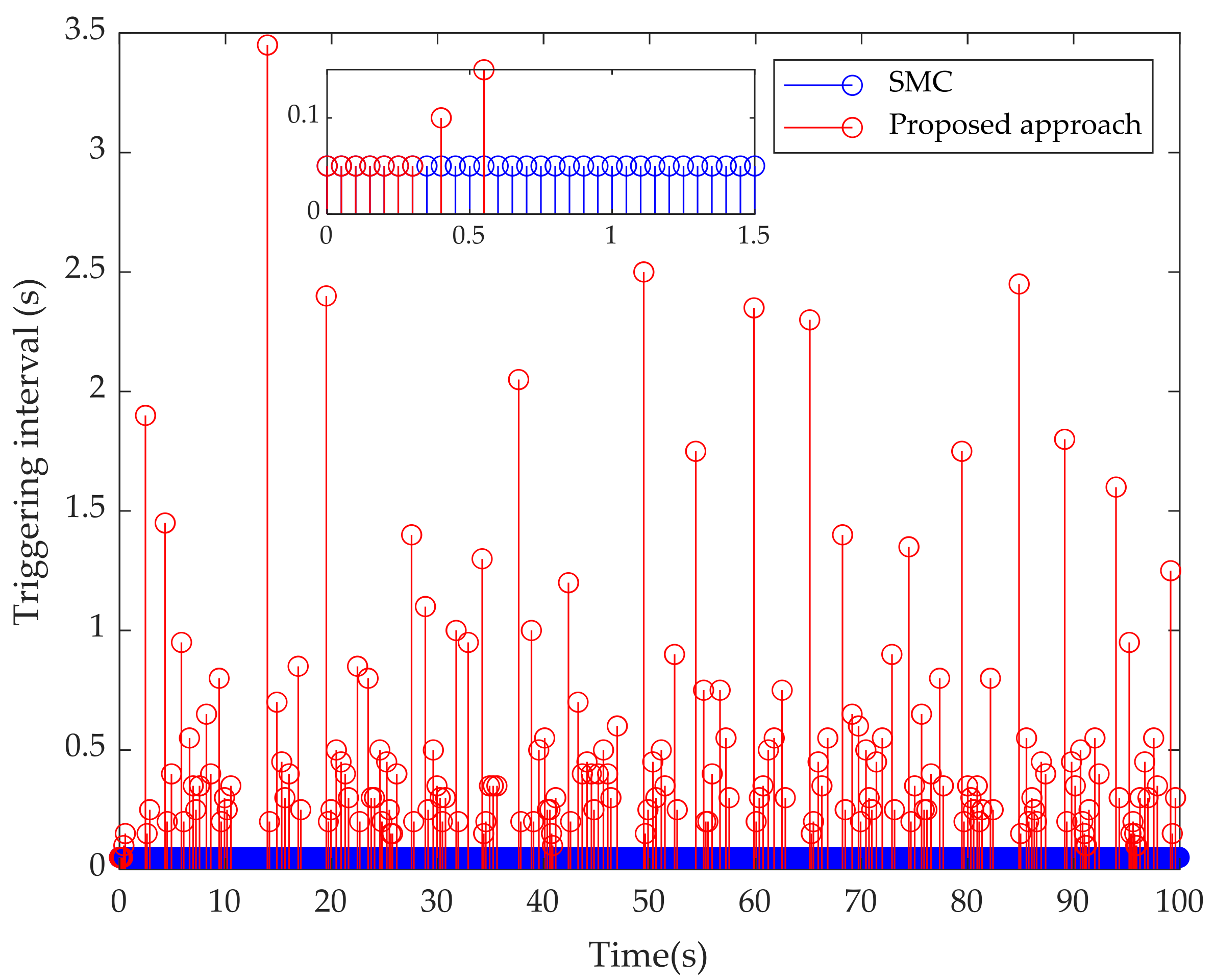
| Maximum communication interval | 0.05 s | 3.45 s | |
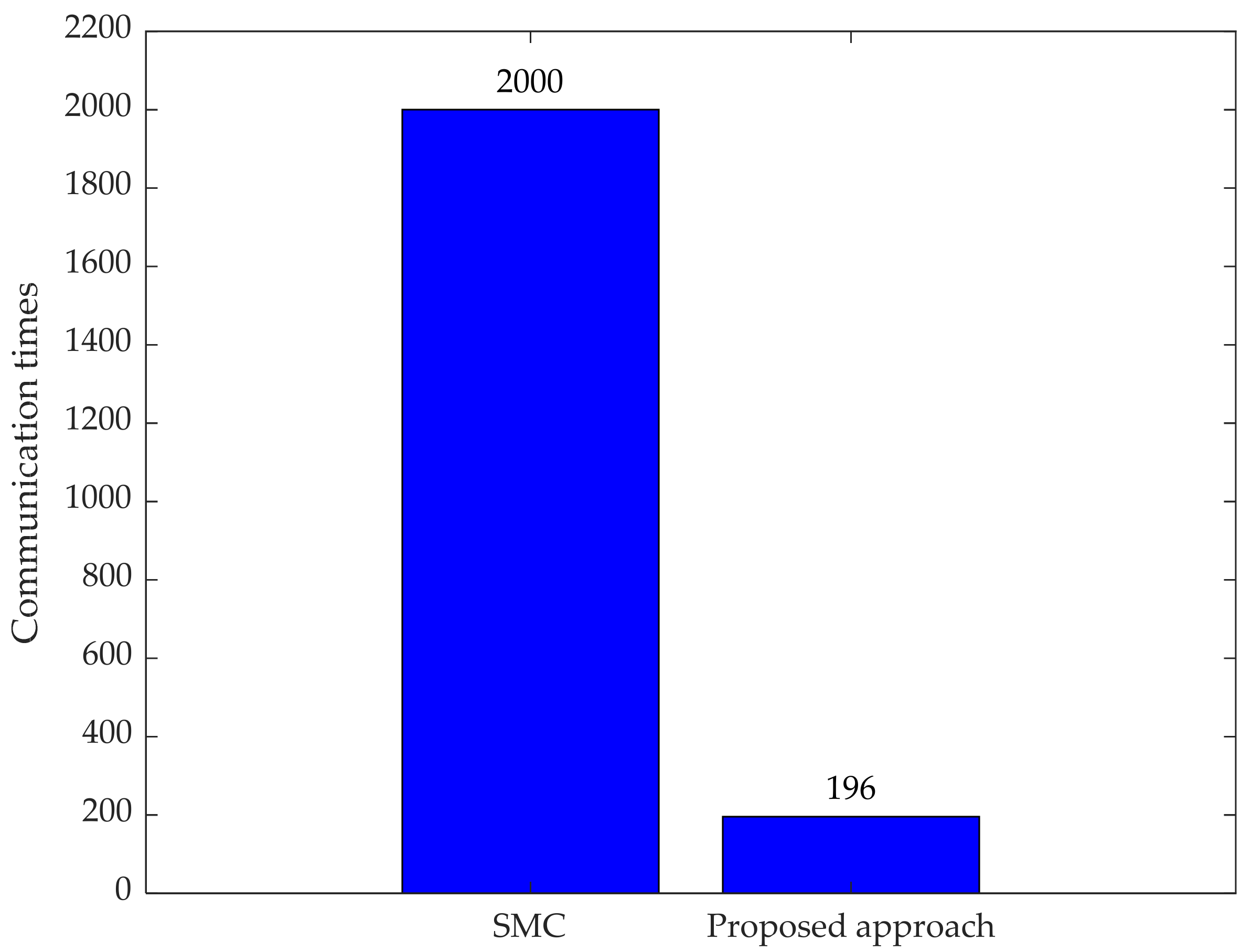
| Communication times (Reduction rate) | 2000 (−) | 196 (90.4%) | |
Publisher’s Note: MDPI stays neutral with regard to jurisdictional claims in published maps and institutional affiliations. |
© 2022 by the authors. Licensee MDPI, Basel, Switzerland. This article is an open access article distributed under the terms and conditions of the Creative Commons Attribution (CC BY) license (https://creativecommons.org/licenses/by/4.0/).
Share and Cite
Qi, J.; Liao, H.; Xu, Y.; Zhu, Z.; You, C. Event-Triggered Attitude-Tracking Control for a Cableless Non-Contact Close-Proximity Formation Satellite. Aerospace 2022, 9, 138. https://doi.org/10.3390/aerospace9030138
Qi J, Liao H, Xu Y, Zhu Z, You C. Event-Triggered Attitude-Tracking Control for a Cableless Non-Contact Close-Proximity Formation Satellite. Aerospace. 2022; 9(3):138. https://doi.org/10.3390/aerospace9030138
Chicago/Turabian StyleQi, Jirong, He Liao, Yufei Xu, Zhu Zhu, and Chaolan You. 2022. "Event-Triggered Attitude-Tracking Control for a Cableless Non-Contact Close-Proximity Formation Satellite" Aerospace 9, no. 3: 138. https://doi.org/10.3390/aerospace9030138