1. Introduction
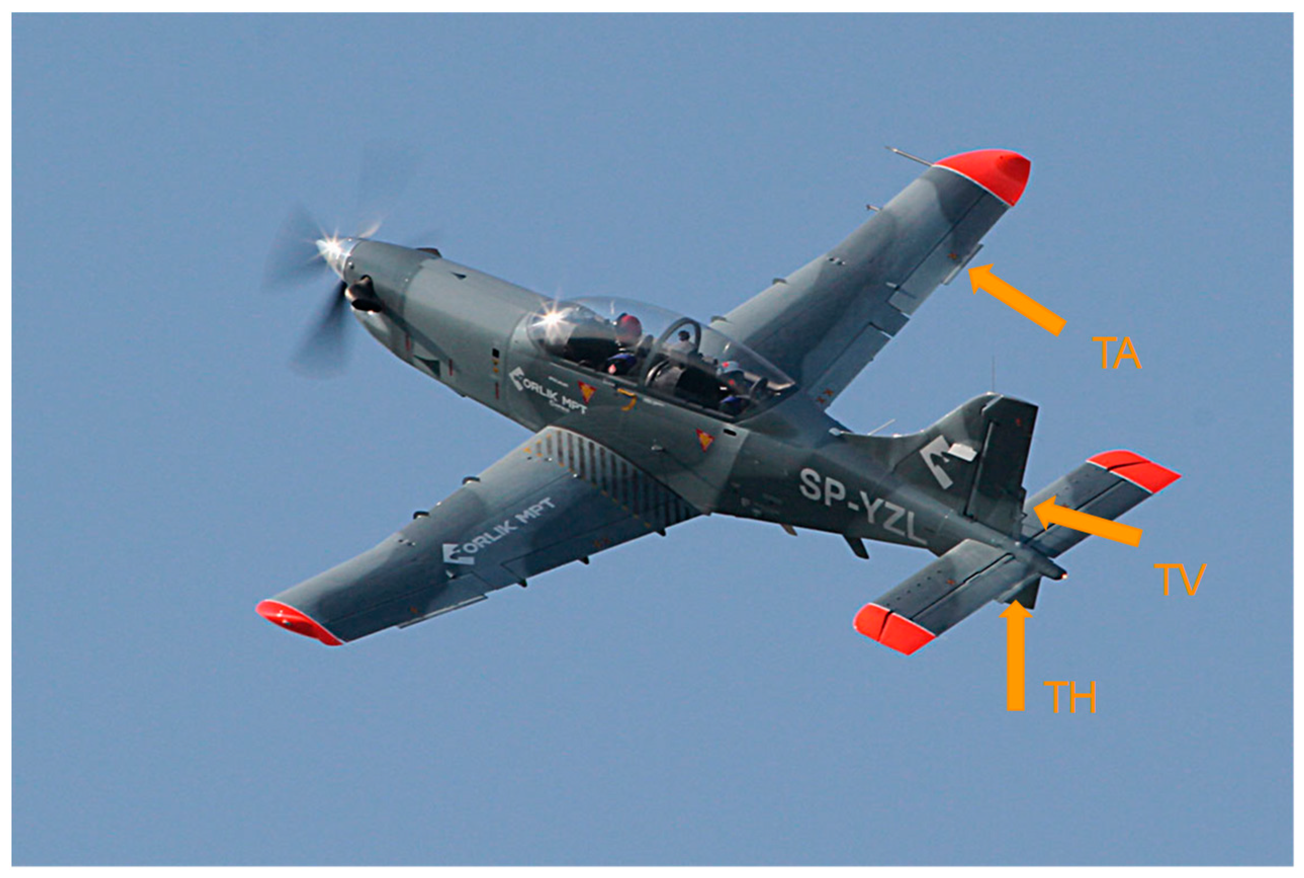
Historically, the slipstream effect became evident during World War II after introducing piston engines and again in the 1970s when propeller-powered civil purpose airplanes were equipped with turbine engines. The same case was with the PZL-130TC-II Orlik, a Polish trainer airplane shown in
Figure 1, that underwent modernization and got the new Pratt & Whitney Canada PT6A 560kW engine. However, the disposable power was quite significant and resulted in apparent difficulties in piloting and the pilot’s discomfort, affecting flight safety. As a result, the PZL-130 TC-II Orlik airplane, earlier classified as Good according to Cooper–Harper rating scale [
1], after the engine replacement was degraded to Fair. As that airplane is used as a trainer at the Polish Air Force Aviation Academy for initial and medium level pilot training, such degradation of piloting characteristics was not acceptable. Therefore, the team of engineers from the Institute of Aviation in Warsaw commenced the development of an automatic rudder trimming system [
2] aiming at yaw compensation induced by slipstream effects. As a result, it was developed, built on the airplane and substantially improved its piloting characteristics.
In recent years, a new requirement related to piloting the airplanes under the IFR rules in controlled aerospace by a single pilot has appeared that requires a two-pilot crew on board when the aircraft does not have an autopilot or flight stabilization system. For airplanes, like PZL-130 TC-II Orlik, it became a limitation in the flights performed from the airfield to the training zones through civil controlled aerospace. Several problems of many kinds appeared because of that requirement. Then, a natural move was to build such a system onboard. After extensive analyses of similar solutions, the decision on developing a flight stabilization system for that airplane was taken. Considering the high efficiency of the yaw stabilization system previously introduced onboard, a similar stabilization method was decided for the two other control channels, pitch and roll-flight altitude and course accordingly. Adding a flight stabilization function or even automatic flight control, a feature specific to autopilots should be feasible by expanding the trimming system capabilities [
3,
4].
Moreover, this development path for flight control automatization seemed to have another advantage. The trimming system is far less complicated than the autopilot. The difference consists in the design of autopilot’s actuators that must be integrated with manual controls and equipped with anti-lock mechanisms of the control system [
5]. By contrast, trimming surfaces actuators are coupled with the manual controls through the electrical control system. Their deflections create hinge moments changing the positions of the main control surfaces, which change the forces felt by the pilot on the joystick and pedals. Thus, the trimming system is mechanically less complex, and it does not require any switching mechanisms or overload clutch engaged in the case of actuator lockage. As a result, an automatic trimming system may constitute an interesting alternative for autopilots, especially for aircraft where:
An autopilot is not of a key system, e.g., as in a trainer airplane that arrives quickly to the exercise zone and does not travel long distances;
An autopilot is too expensive, which is the case with economic ultralight aircraft and small general aviation aircraft;
IFR single-pilot operations in controlled airspace are planned.
The cost-benefit of a trimming system extended with an automatic flight control function over an autopilot is obvious and stems from the following facts:
It does not require any substantial changes and extensions of the onboard elements or systems;
It has a simple mechanical design;
It provides automatic trimming at the same time;
Certification costs for trimming system (classified as Level C according to the DO-178 recommendation: Software resulting in a major failure condition for the system) are lower than for autopilot (Level B DO-178 recommendation: Software resulting in a hazardous or severe-major failure condition for the system) [
6].
The flight stabilization system designing process was initiated with the extensive analyses of requirements for the system functionalities and specifications of the airplane’s operational capabilities, onboard systems and civil and military standards related to such systems. As a result, the specific requirements and expectations of the PZL-130 TC-II Orlik airplane’s user were:
- -
Keeping unchanged the way of the airplane’s flight controlling, among this it’s trimming,
- -
Certifying the developed system according to the EASA Form 1 requirements,
- -
Keeping the onboard power supply system and other installations, like hydraulic and pneumatic, unchanged.
Automatic trimming systems for pitch and roll channels should be included in the existing classical trimming system, operated manually with the fly-by-wire type installation. It should also fit the existing frame spaces and electric installation. The new trimmers controlling hardware and software needed to be developed, designed, built and tested (on the ground and during the flight).
The hardware modules of that system were the following: trimmers’ control panels for two pilot cabins, servomechanisms (one for each control channel), computer controlling automatic stabilization flight mode and cabling. The key module for the successful development of the system was the automatic flight control computer and, in fact, the development of the control laws allowing for that.
The proposed automatic stabilization and control system is a state machine performing transitions between three operating modes:
Manual control;
Manual control with automatic rudder trimmer control;
Fully automatic flight control with automatic trimming of rudder, elevator, and ailerons.
While executing the third mode, the automatic trimming in all three control channels runs in the background. What is noticeable from the pilot’s point of view is that when the crew takes back control, the aircraft is properly trimmed, allowing for an easy transition.
2. Initial Verification of the Assumed Hypothesis
At the first stage of an automatic trimming system design, it had to be determined if it was feasible to control the aircraft manually using trimmers. A positive result of such a test would allow for maintaining its non-hazardous system category.
The flight tests were planned to verify the possibility of maintaining the manual control using trimmers. During the tests, the pilot could use the classic set of controls: the control stick and pedals or move the trimmers only with the additional manipulator(s). Trimmers were controlled with two joysticks: one right hand operated to move the elevator and aileron trimmers, and the other left hand operated to move the rudder trimmer.
The test pilot, with many hours of experience in the PZL-130 Orlik aircraft, was instructed to begin with the simplest maneuvers, i.e., stabilizing the straight flight manually with the use of trimmers only. Then, he was supposed to move on to more difficult tasks: change of a course, change of flight altitude, and simultaneous course and altitude changes. In the pilot’s opinion, the complex maneuvers were not especially demanding. Nevertheless, the aircraft behaviour was rated at least as
Fair. The set of test flights was concluded with a complex aerobatic figure, a barrel roll, presented in
Figure 2. Currently, there are works on automating such complicated maneuvers [
7], which proves the feasibility of their performance by automatic flight control systems.
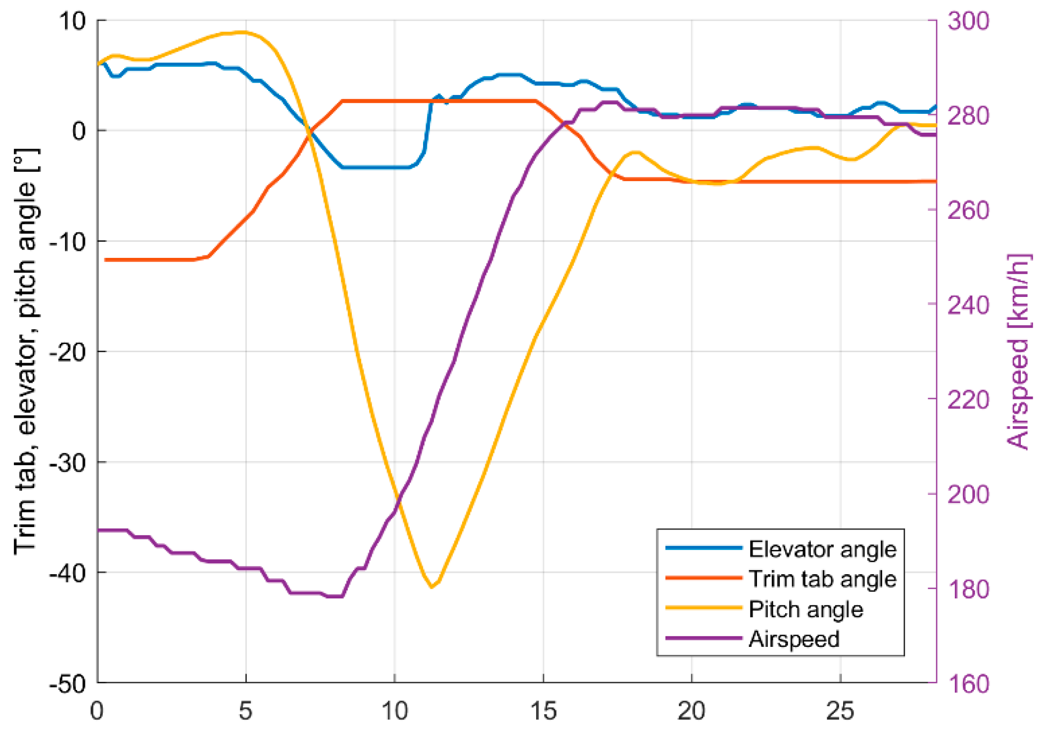
The next test phase aimed to confirm if the trimming system could be certified as a Level C system, meaning a non-hazardous one. It had to be proven that safe flight might be continued in the worst case of system failure when trimmers stay locked in an extreme position. Flight tests covered the following sequence: the pilot sets trimmers to the extreme position. After a few seconds, he tries to control the aircraft manually, compensating the significant trimmers’ adverse effects.
Figure 3 shows the simulated elevator trimmer failure results when it moved and stayed locked in its extreme position at 3°, causing a sudden increase of pitch angle. The trim deflection limits of the Orlik aircraft control surfaces are as follows: −20–12° for aileron, −12–25° for rudder and −20–3° for the elevator. Asymmetries result from the nonzero neutral angle position of the trimming surface. From the flight safety point of view, the longitudinal control channel was chosen as the most difficult and dangerous one. At the beginning of the maneuver, the pilot tried to maintain a steady flight for 3 s. During this time, the airspeed dropped 12 km/h, and the pitch angle was about 6–8°. After the extreme elevator trim tab deflection in 8th s, the aircraft goes into a nosedive with a pitch angle below −40° and airspeed increase from 178 km/h to 227 km/h. Next, he tried to compensate the pitch angle changes to achieve the flat flight. He succeeded in doing it despite the significant increase of the forces on his joystick. What is important is that the pilot was still able to perform manual recovery by changing the elevator position in 11th s. After the pitch angle achieved −10°, the pilot trimmed the aircraft manually appropriately to a newly levelled flight airspeed.
Except for the two presented maneuvers, the flight test campaign included many others required by European and American aircraft design regulations, such as:
Nose-down recovery with an elevator trim tab at its limit, initial airspeeds from 190 to 375 km/h range,
Nose-up recovery with an elevator trim tab at its limit, initial airspeeds from 190 to 375 km/h range,
Right barrel roll, initial airspeeds 300 km/h and 375 km/h,
Left barrel roll, initial airspeeds 300 km/h and 375 km/h,
Right and left turns,
Reaction to right and left limit rudder trim tab setting,
Climbs and descents,
Stick-free cruise flight controlled only by the use of trim tabs.
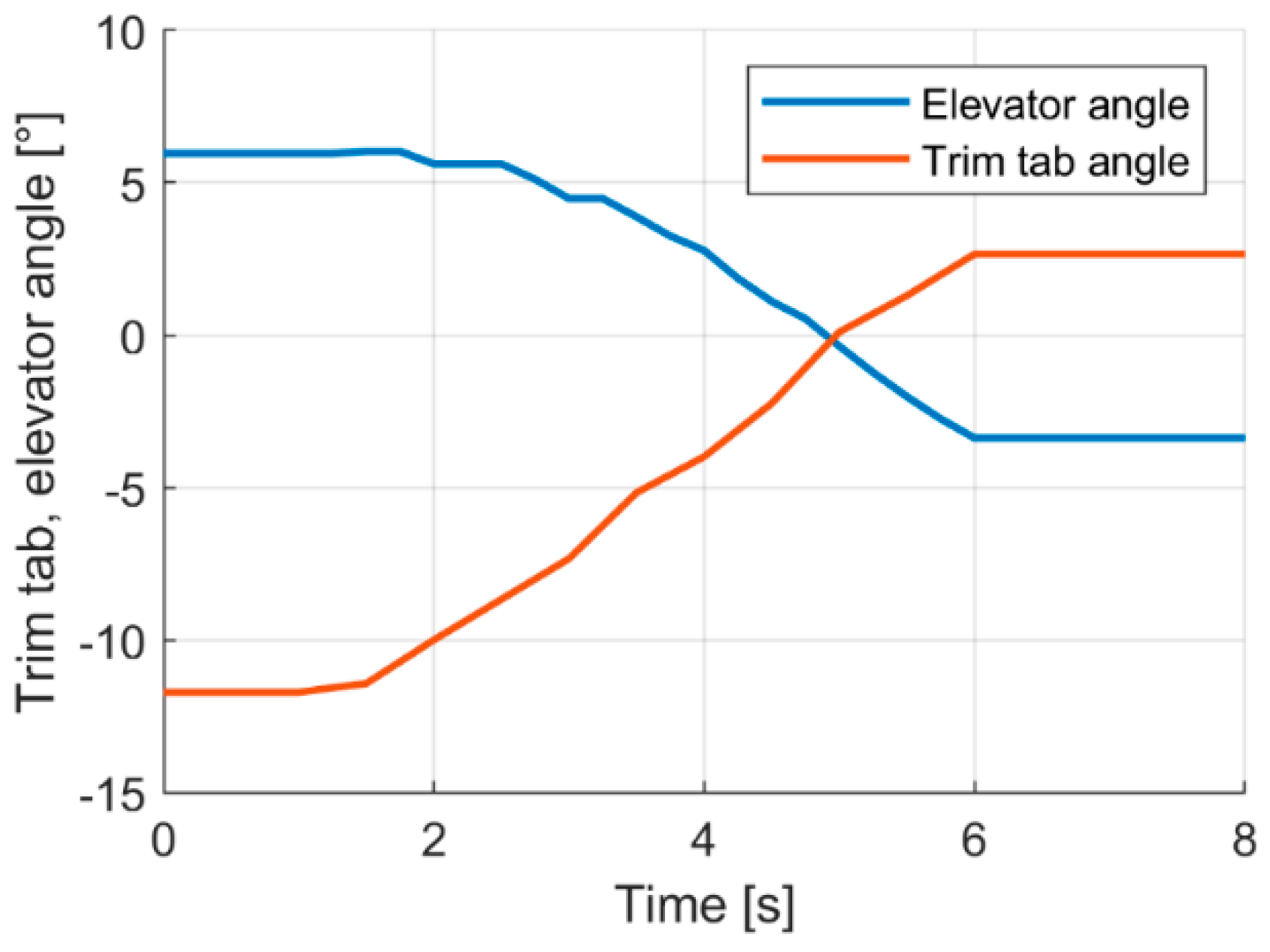
The flight parameters were recorded during the described flight tests to perform a post-flight analysis. Part of the obtained results is presented in
Figure 4, showing how the elevator deflects due to its trim tab deflection. In this test, a pilot let go of the stick and controlled only the elevator trim table until 5 s; the flight was level at 185 km/h. Then, due to the aerodynamic coupling, the trim tab caused the elevator to deflect, and the aircraft began its descent.
The analysis provided evidence to confirm the research hypothesis and delivered data to determine the transfer functions (1) that show the dependence between trimmer and corresponding control surface deflection.
Analyzing the Formula (1), it is evident that it is not feasible to induce the control surface movement from the upper to the lower limit by deflecting the trimmer. Thus, the designed system is inefficient at low speed when the minimum and maximum control surface deflections are necessary. Due to this limitation, the automatic flight stabilization system using trimmers installed in aircraft already in service may not be adequate for automatic take-off and landing. To make it feasible for these flight phases, changes in the design of trimmers and control surfaces may be required.
where:
s—Laplace operator,
—elevator deflection,
—elevator trim tab deflection,
—aileron deflection,
—aileron trim tab deflection,
—rudder deflection, and
—rudder trim tab deflection
3. Model-Based Design
The preliminary flight tests validated proof of concept of the trim tab stabilization system. The next stage was the system’s design based on its mathematical models. At first, an airplane model was created, and its parameters were identified from flight and CFD data. Then, before hardware manufacturing, models in the loop simulations were performed. Due to the future certification plans, a classical cascade controller was designed with outer and inner loops, including PI and PID regulators in the altitude and heading channels. Using newer, more complex methods [
8,
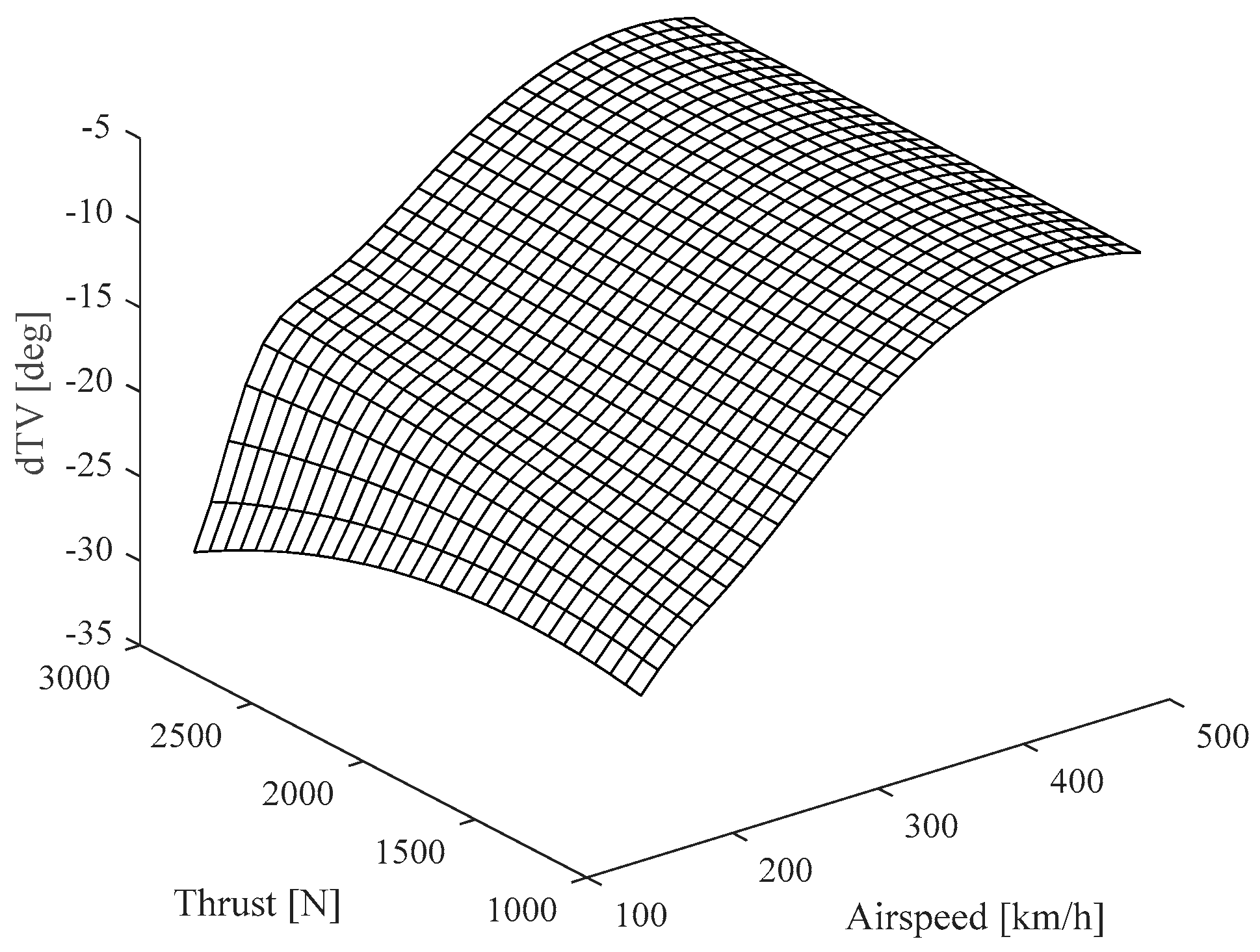
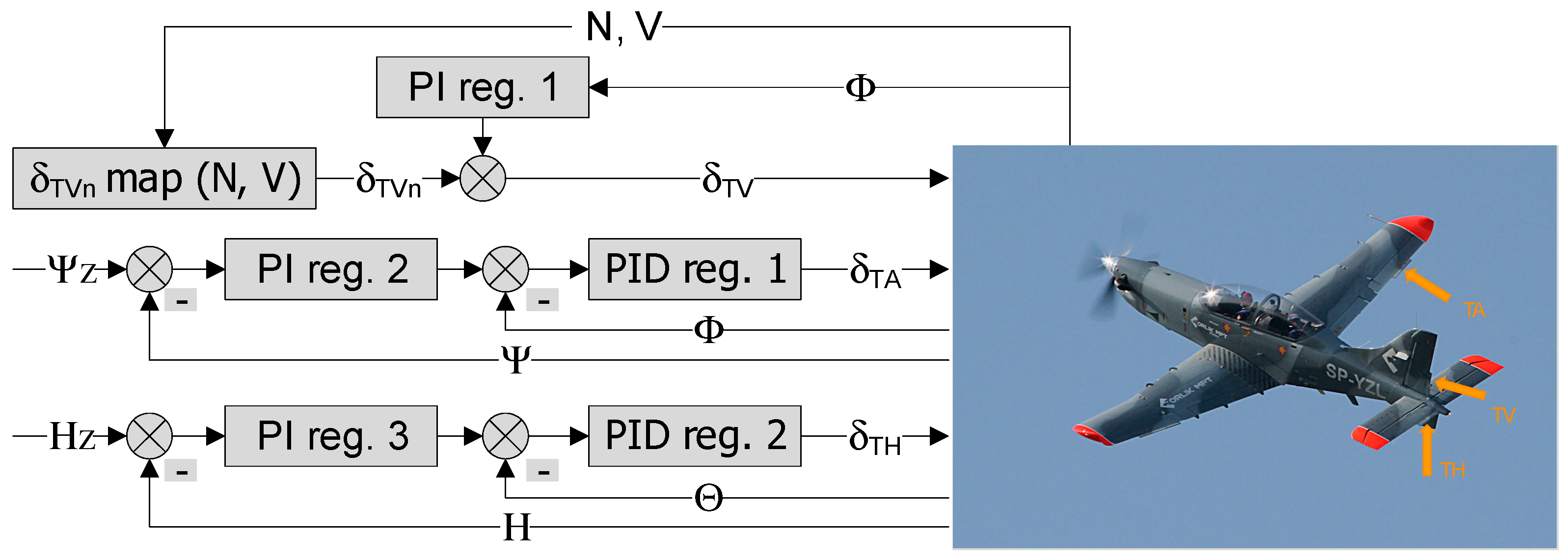
9] can significantly slow down or even prevent certification. Finally, control channels were separated—the altitude channel actuates only the elevator trim tab, the heading channel—only the aileron trim table. The third channel actuates the rudder trim tab based on a predefined lookup table based on flight test results (
Figure 5) with a partial correction from the PI regulator (
Figure 6). The lookup table is three-dimensional in the form of a surface called a map. Analyzing
Figure 5, we conclude that the equivalent deflections of the rudder trimmer are a function of the current flight speed and the power of the propulsion system.
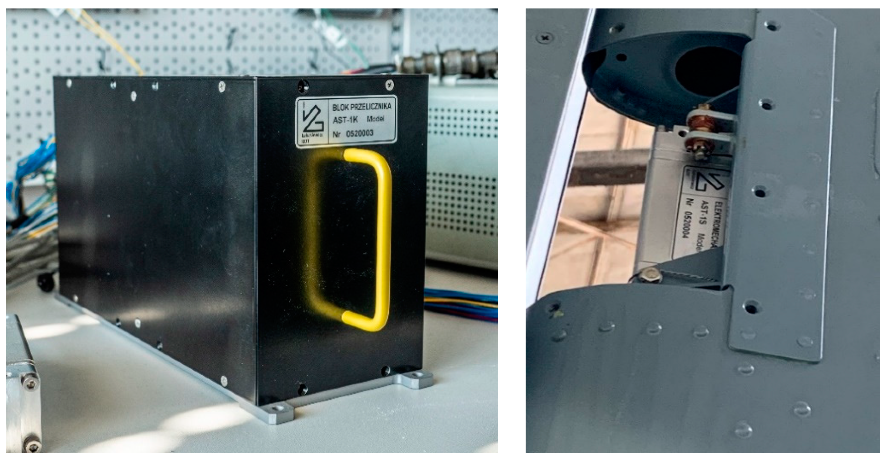
Using the Bode plot forming method, the controllers were tuned with linearized models around average level cruise flight velocity, altitude operating points and airplane weight and balance typical for a training mission. First, the operating points were computed using Matlab Model Trimming tools. Then, the model was also automatically linearized at that point in the Model Linearizer tool generating the state-space form of the models. Next, controllers’ coefficients tuning was done graphically using Bode plot tools. Then, those tuned coefficients values were returned with a nonlinear airplane model in the real-time simulations. The developed models were verified after the hardware parts were manufactured: stabilization system computer and trim tab servomechanisms (
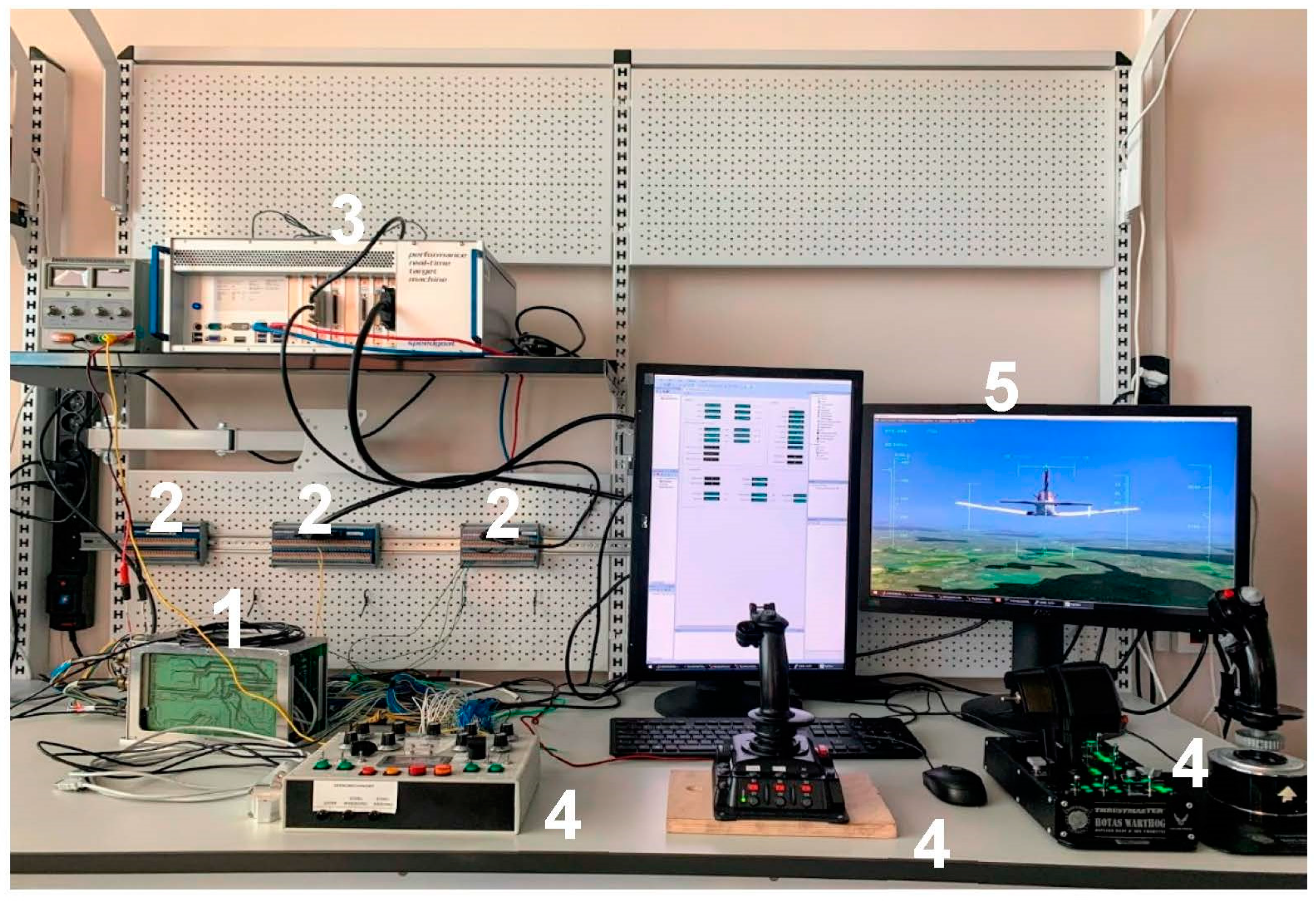
Figure 7). For that purpose, the hardware in the loop (HIL) simulations [
10,
11] were performed on a stand designed for this kind of research (
Figure 8). Before installation on aircraft, a pilot in the loop (PIL) simulations performed at that stand with mounted stabilization system’s hardware allowed to fine-tune the system performance, using the launch aircraft pilot’s opinions.
4. Pre-Flight Simulation Results
In pre-flight simulations, the two main goals were:
To verify the feasibility of fulfilling the requirements by the developed system,
To define the best values of flight stabilization system coefficients for as broad a range of the launch airplane flight envelope as possible.
Pre-flight simulation testing covered many scenarios defined in the test plan of the flight stabilization system. Finally, some chosen simulation results were presented to show and discuss the achieved results.
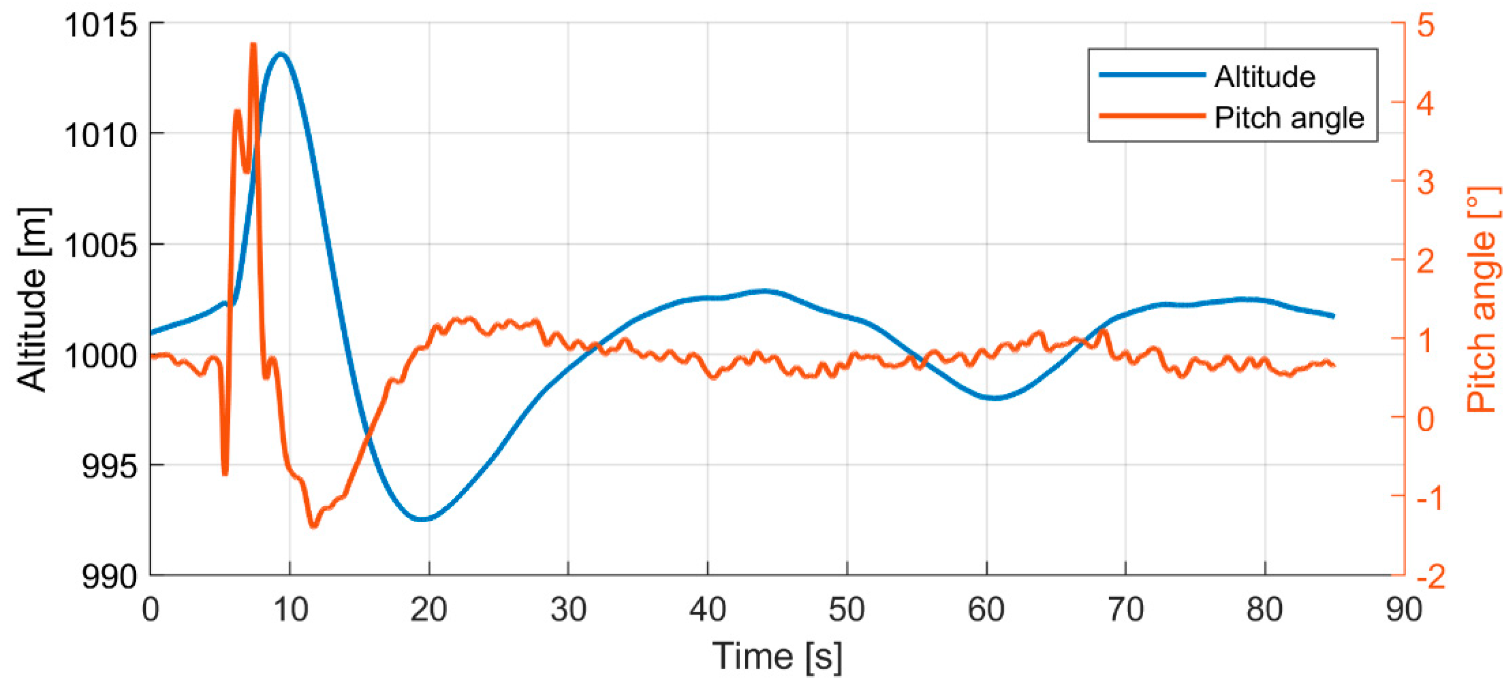
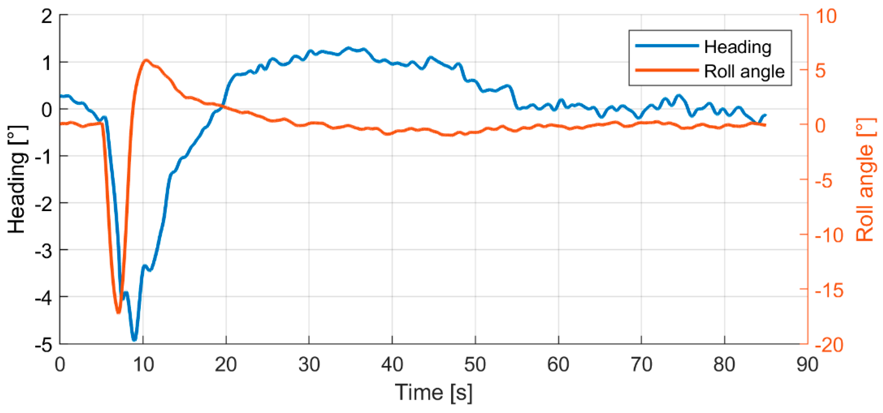
Example results show stabilization performance in case of atmospheric disturbance that causes pitch and roll rate 15°/s increase for 2 s (
Figure 9 and
Figure 10). In this scenario, both altitude and heading channels are affected simultaneously. In the beginning, the airplane is in a stabilized cruise flight, and the disturbance starts at the 5th second of the simulation. The shape of the responses is also influenced by the Dryden turbulence used in the environment model. Initially, the disturbance causes an altitude increase of 14 m and a heading decrease of −5°. As a result, the pitch angle rises to 4.9°, and the roll angle decreases to −17°. The system stabilizes initial disturbance after about 25 s in altitude with undershoot reaching 7.5 m at 19 s of simulation. Pitch angle stabilizes after 15 s from disturbance start (
Figure 9). Heading and roll angles stabilize after 15 s from the disturbance occurrence with a small 1° overshoot (
Figure 10).
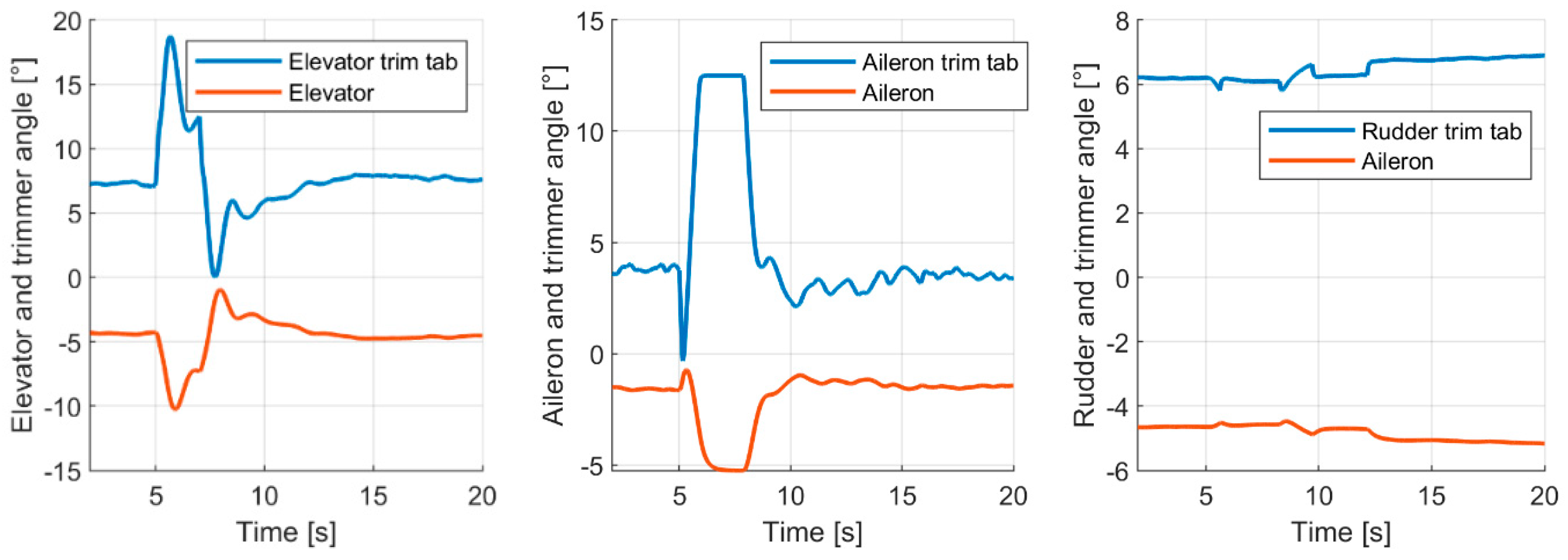
Figure 11 shows elevator, aileron and rudder trim tab angles commanded by the stabilization system controller and corresponding primary control surfaces deflections. The graphs are limited to 20 s of simulation because the deflections were stable after that time. Those example simulation results prove the achieved effectiveness of the flight stabilization system using trimming tabs.
The possibility of applying the developed system to stabilize the launch airplane flight was tested and confirmed within the flight velocities from the landing approach velocity up to the maximum operational velocity.
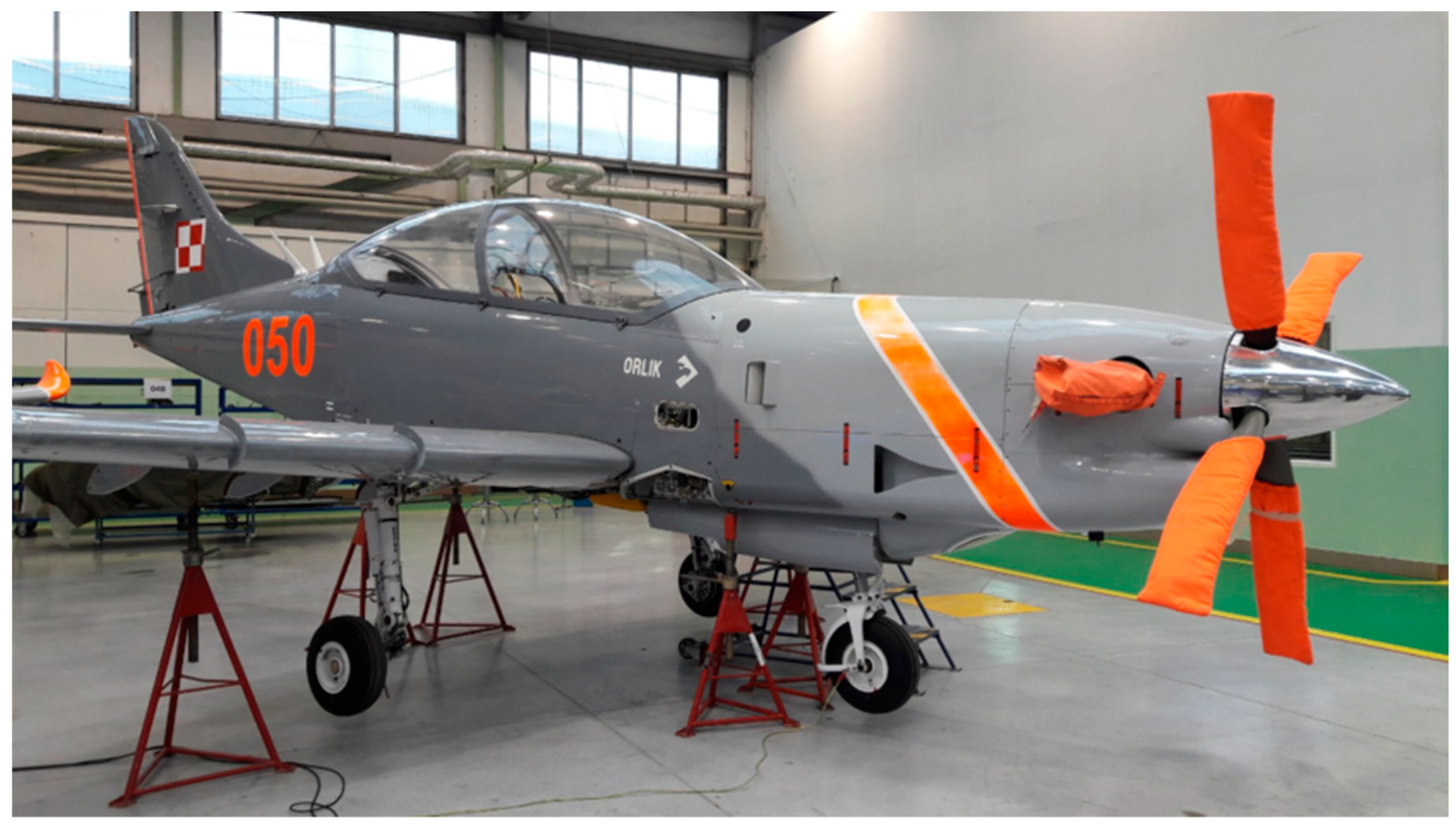
5. Installation on Aircraft and Ground Tests
The set of tests preceded the installation of the stabilization system’s hardware modules on the airplane, according to the DO-160G environmental standard requirements. After passing laboratory tests [
12,
13], the system was installed on PZL 130 TC-II Orlik airplane (
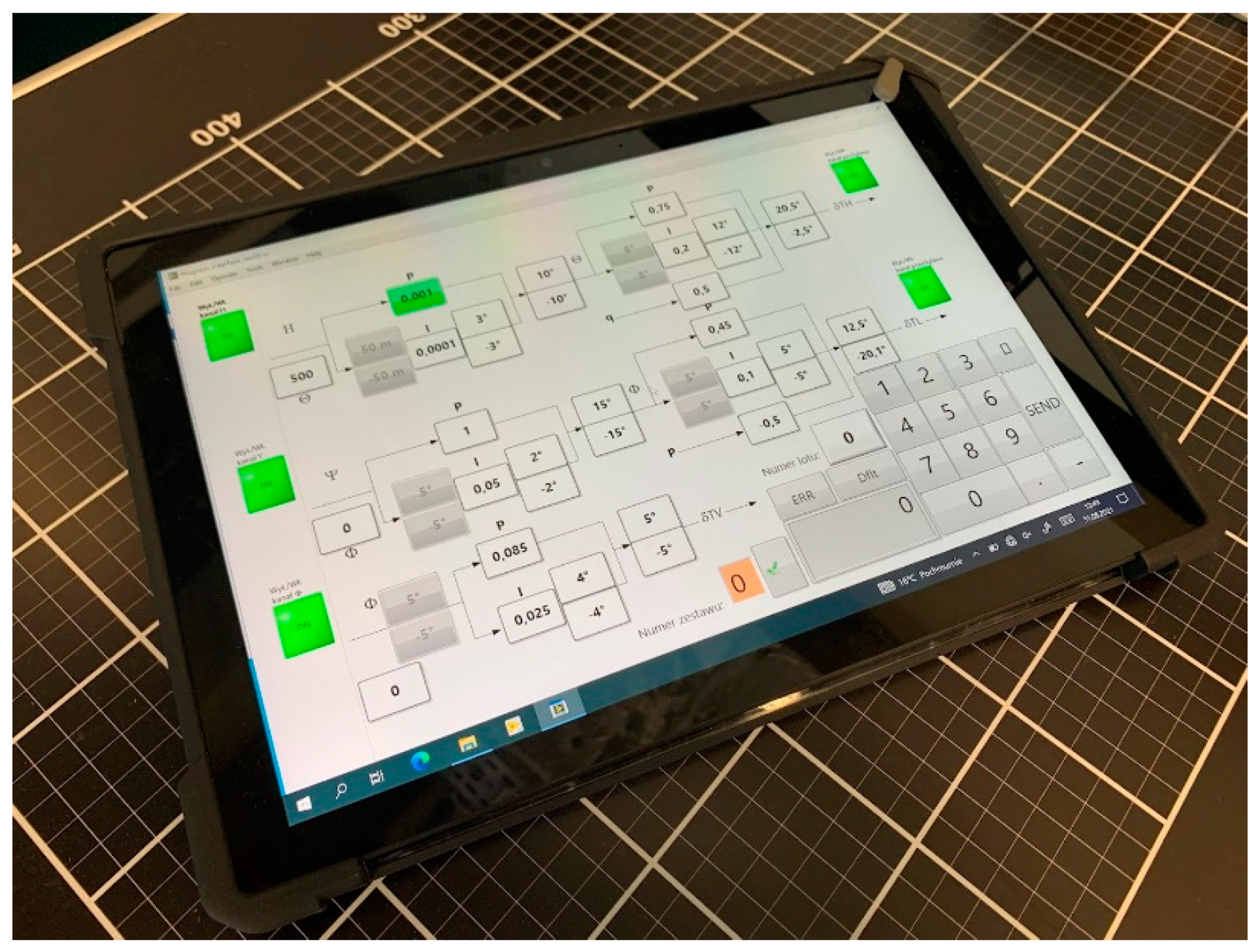
Figure 12) and underwent ground tests performed under the supervision of the Polish Civil Aviation Authority. Ground tests covered typical checks: electrical wiring, trim tab calibration and polarity, interface, cabin controls, emergency cut-off, failure detection, diagnostics. In addition, a special application installed on the dedicated ruggedized laptop with a touch screen interface (
Figure 13) was developed to handle diagnostics and calibration of the system at the aircraft.
Flight tests are the costliest stage of an avionics project. Therefore, another application was developed to minimize the expensive test flights number. It was dedicated to the flight engineer to allow him to change the stabilization system controller parameters during the flight (
Figure 13). The experienced flight test engineer can tune controller parameters and see the result immediately during one flight, eliminating the need for landing, on-ground tuning, and verifying introduced changes in the next test flight. Moreover, several parameter sets can be tested in one flight instead of one set, as in the former method. During the ground tests, the flight engineer positively assessed the application and its graphical interface.
All the performed research and tests show the capabilities and effectiveness of the proposed solution. Extensive ground test results confirmed their passing by the Polish Civil Aviation Authority. The whole developed flight stabilization system using the trimming surfaces was ready for the flight tests, which will be the final stage of its validation.
6. Conclusions and Final Remarks
The various automatic control methods for designing the stabilization flight were checked. Many of them appeared to be effective and could be applied. However, the final choice of a control method was caused by the feasibility of its certification according to the rules and requirements of the EASA Form 1 certification. Therefore, the classical type of control methods was applied to that project.
The stabilization system development described in the paper was at the final stage, which could be performed on the ground. Before initiating the flight tests, extensive research and tests were performed. They were based on the substantial use of PIL, HIL simulations and environmental testing laboratory tests. The final ground tests stage was supervised by the Polish Civil Aviation Authority, according to certification standards.
The developed airplane flight stabilization system using the trimming surfaces showed its safety and efficiency during all ground phases of development. The SIL, HIL and PIL simulations proved its capability of flight parameters stabilization in the full cruising flight velocities range. That stabilization is effective in the three channels in parallel, i.e., the effective three-dimensional automatic flight control system was developed.
It can stabilize the flight in the typical operating conditions and act as autopilot in the range of the cruising flight velocities. However, it would require connecting it with the onboard navigation system and interface, allowing the pilots for introducing the given flight parameters, like altitude and velocity.
The developed system is planned to be certified after completing the flight tests. That certification with Form 1 certificate will allow installing that system onboard the GA airplanes not equipped with the autopilot. The launch airplane will be the PZL-130 TC-II Orlik turboprop training airplane.
Such a certified stabilization system will fulfil the appropriate requirements and specifications and allow for performing single-pilot flights in the controlled airspace in the IFR conditions.
Thanks to supporting the pilots in their piloting duties, the presented stabilization system will substantially increase the safety of the GA airplanes performing the flights according to the Free Sky conditions. It will take away from the pilots the simple piloting activities and allow them to perform the navigation and communication with ground control duties. It is particularly important for the not experienced pilots exploiting the GA aircraft.
The proposed system goes into the more electric and future electric aircraft direction. It will allow replacing the heavy hydraulic autopilots’ effectors onboard systems with lighter electrical solutions. In small aircraft, such a system can act as a simplified autopilot stabilizing the current flight parameters and will not require a substantial increase of the electric power installed onboard those airplanes.
Author Contributions
Conceptualization, A.Z., M.K. and C.S.; methodology, M.K. and C.S.; software, A.Z.; validation, A.Z.; formal analysis, A.Z.; investigation, A.Z.; resources, A.Z.; data curation, A.Z.; writing—original draft preparation, A.Z., M.K. and C.S.; writing—review and editing, A.Z., M.K. and C.S.; visualization, A.Z.; supervision, M.K. and C.S.; project management, C.S.; funding acquisition, C.S. and M.K. All authors have read and agreed to the published version of the manuscript.
Funding
Research described in that paper has been funded under the EU co-financed project number POIR.04.01.02-00-0006/17-00, titled “Innovative system of flight stabilization with use of trimmers”—ISSLOT.
Data Availability Statement
The data relating to that paper are stored and managed in the Lukasiewicz Research Network—Institute of Aviation. They are not publicly available as they are related to the IPR of the airplane manufacturer Airbus Poland S.A.
Conflicts of Interest
The authors declare no conflict of interest.
References
- Cooper, G.E.; Harper, R.P. The Use of Pilot Rating in the Evaluation of Aircraft Handling Qualities; National Aeronautics and Space Administration: Washington, DC, USA, 1969.
- Krawczyk, M.; Graffstein, J. Propozycja systemu eliminującego szkodliwe odziaływanie strumienia zaśmigłowego w samolotach turbośmigłowych. Sci. Lett. Rzesz. Univ. Technol. Mech. 2013, 30, 287–295. [Google Scholar] [CrossRef] [Green Version]
- Levy, D. Design of a full time wing leveler system using tab driven aileron controls. In Proceedings of the Guidance, Navigation and Control Conference, Hilton Head Island, SC, USA, 10–12 August 1992. [Google Scholar] [CrossRef] [Green Version]
- Jenks, G.E.; Henry, H.F.; Roskam, J. Flight Test Results for a Separate Surface Stability Augmented Beech Model 99; Technical Report; National Aeronautics and Space Administration: Edwards, CA, USA, April 1977.
- Vehicle Management Systems-Flight Control Function, Design, Installation and Test of Piloted Military Aircraft, General Specification for AS94900A; SAE International: Warrendale, PA, USA, 2018.
- Gohil, K. Software Considerations in Airborne Systems and Equipment Certification; Radio Technical Commission for Aeronautics: Washington, DC, USA, 1992. [Google Scholar]
- Rogalski, T.; Rzucidło, P.; Prusik, J. Unmanned aircraft automatic flight control algorithm in a spin maneuver. Aircr. Eng. Aerosp. Technol. 2020, 92, 1215–1224. [Google Scholar] [CrossRef]
- Asa, E.; Yamamoto, Y. Aircraft Flight Stabilizer System by CDM Designed Servo State-Feedback Controller. Aerospace 2021, 8, 45. [Google Scholar] [CrossRef]
- Efremov, A.V.; Mbikayi, Z.; Efremov, E.V. Comparative Study of Different Algorithms for a Flight Control System Design and the Potentiality of Their Integration with a Sidestick. Aerospace 2021, 8, 290. [Google Scholar] [CrossRef]
- Dolega, B.; Rogalski, T. The new conception of the laboratory testing of the FBW control system for small aircraft. Aircr. Eng. Aerosp. Technol. 2004, 76, 293–298. [Google Scholar] [CrossRef]
- Kiesbye, J.; Messmann, D.; Preisinger, M.; Reina, G.; Nagy, D.; Schummer, F.; Mostad, M.; Kale, T.; Langer, M. Hardware-In-The-Loop and Software-In-The-Loop Testing of the MOVE-II CubeSat. Aerospace 2019, 6, 130. [Google Scholar] [CrossRef] [Green Version]
- Krawczyk, M.; Zajdel, A.; Szczepański, C. Simulation and Testing of Flight Stabilisation System Using Trimmers. In Conference on Automation; Springer: Cham, Switzerland, 2021; Volume 1390, pp. 185–196. [Google Scholar] [CrossRef]
- Szczepanski, C.; Krawczyk, M.; Zajdel, A. The airplane trim system–new functionalities. Aircr. Eng. Aerosp. Technol. 2020, 92, 1401–1406. [Google Scholar] [CrossRef]
Figure 1.
PZL-130TC II Orlik trainer aircraft. Arrows indicate trimmers location (By Maciej Szopa/Aviation International).
Figure 1.
PZL-130TC II Orlik trainer aircraft. Arrows indicate trimmers location (By Maciej Szopa/Aviation International).
Figure 2.
PZL-130TC II Orlik flight parameters during the barrel roll maneuver.
Figure 2.
PZL-130TC II Orlik flight parameters during the barrel roll maneuver.
Figure 3.
Manual recovery from a nosedive caused by elevator trim tab failure in a pitch control channel.
Figure 3.
Manual recovery from a nosedive caused by elevator trim tab failure in a pitch control channel.
Figure 4.
Example flight test results of elevator deflection caused by its trim tab deflection.
Figure 4.
Example flight test results of elevator deflection caused by its trim tab deflection.
Figure 5.
Three-dimensional lookup table defining rudder trim position.
Figure 5.
Three-dimensional lookup table defining rudder trim position.
Figure 6.
Stabilization system controller structure. Where: N—engine shaft torque, V—airspeed, Φ—roll angle, Θ—pitch angle, Ψ—yaw angle, HZ—reference altitude, ΨZ—reference yaw angle, δTVn—rudder trim tab position from the map, δTV—rudder trim tab position output, δTA—aileron trim tab position output, and δTH—elevator trim tab position output.
Figure 7.
Stabilization system computer (left) and elevator trim tab servomechanism installed on the aircraft (right).
Figure 7.
Stabilization system computer (left) and elevator trim tab servomechanism installed on the aircraft (right).
Figure 8.
Hardware in the loop simulation test stand: 1—Device under test, 2—interface terminal boards, 3—real-time target computer, 4—input devices, and 5—visualization.
Figure 8.
Hardware in the loop simulation test stand: 1—Device under test, 2—interface terminal boards, 3—real-time target computer, 4—input devices, and 5—visualization.
Figure 9.
Altitude and pitch angle stabilization after disturbance.
Figure 9.
Altitude and pitch angle stabilization after disturbance.
Figure 10.
Heading and roll angle stabilization after disturbance.
Figure 10.
Heading and roll angle stabilization after disturbance.
Figure 11.
Elevator, aileron, rudder, and their trim tabs deflection angles during stabilization.
Figure 11.
Elevator, aileron, rudder, and their trim tabs deflection angles during stabilization.
Figure 12.
PZL 130 TC-II Orlik during a ground test (By Juliusz Sabak/Defence24.pl).
Figure 12.
PZL 130 TC-II Orlik during a ground test (By Juliusz Sabak/Defence24.pl).
Figure 13.
In-flight controller tuning application installed on the dedicated laptop.
Figure 13.
In-flight controller tuning application installed on the dedicated laptop.
| Publisher’s Note: MDPI stays neutral with regard to jurisdictional claims in published maps and institutional affiliations. |
© 2022 by the authors. Licensee MDPI, Basel, Switzerland. This article is an open access article distributed under the terms and conditions of the Creative Commons Attribution (CC BY) license (https://creativecommons.org/licenses/by/4.0/).


