
Lessons Learned from IDEASSat: Design, Testing, on Orbit Operations, and Anomaly Analysis of a First University CubeSat Intended for Ionospheric Science

 , , ,
, , ,
Abstract
:
1. Introduction
2. Materials and Methods—Implementation, Integration, and Testing of the IDEASSat Flight Model
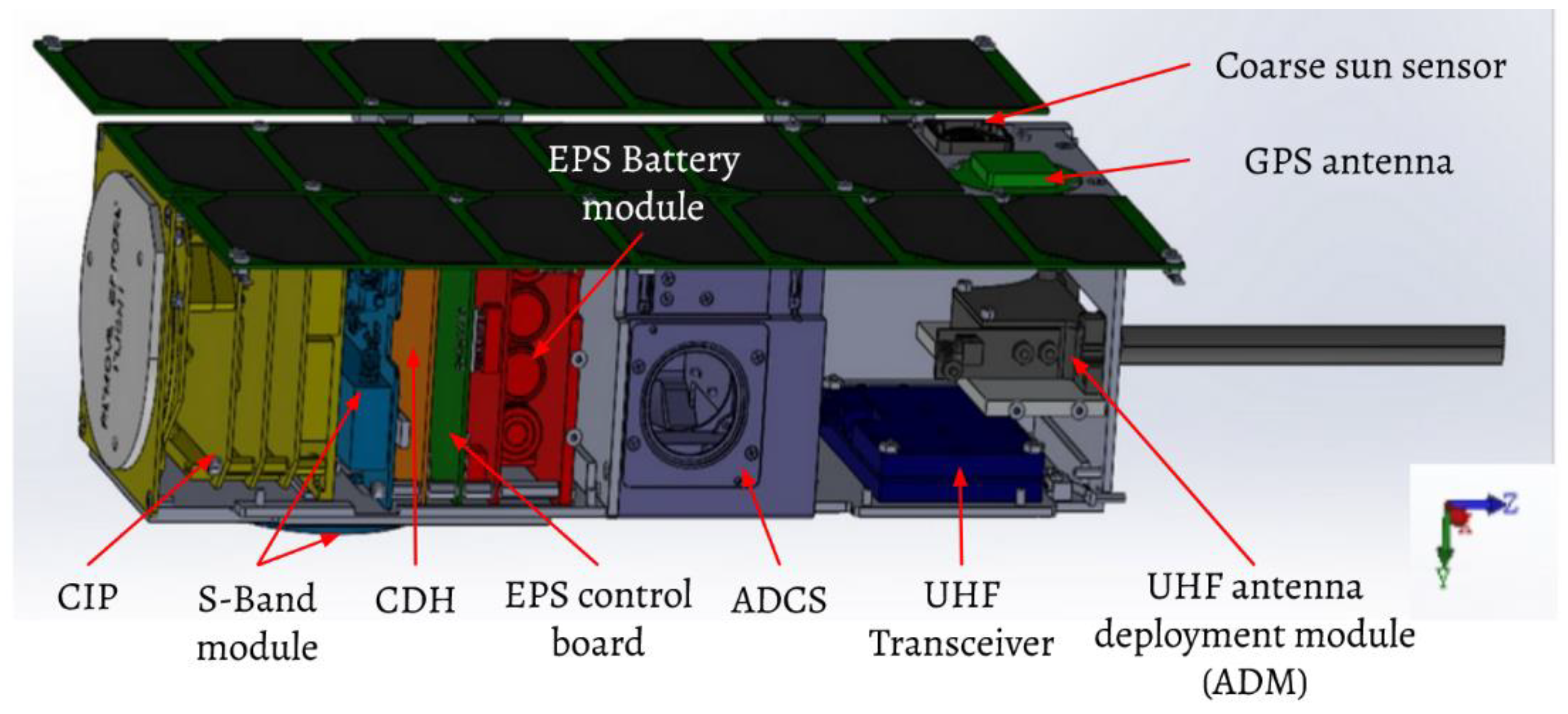
2.1. IDEASSat Satellite Subsystems
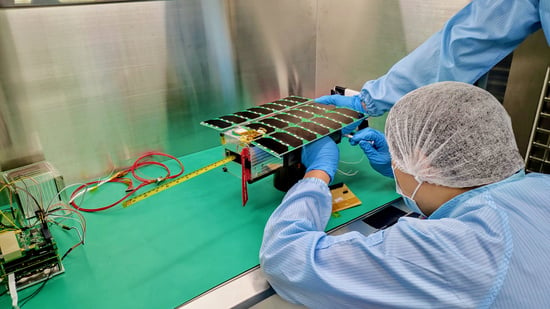
2.1.1. Structure and Mechanisms (STR)
2.1.2. Thermal Control Subsystem (TCS)
2.1.3. Electrical Power Subsystem (EPS)
2.1.4. Telecommunication Subsystem (COMM)
2.1.5. Attitude Determination and Control Subsystem (ADCS)
2.1.6. Command and Data Handling (CDH)
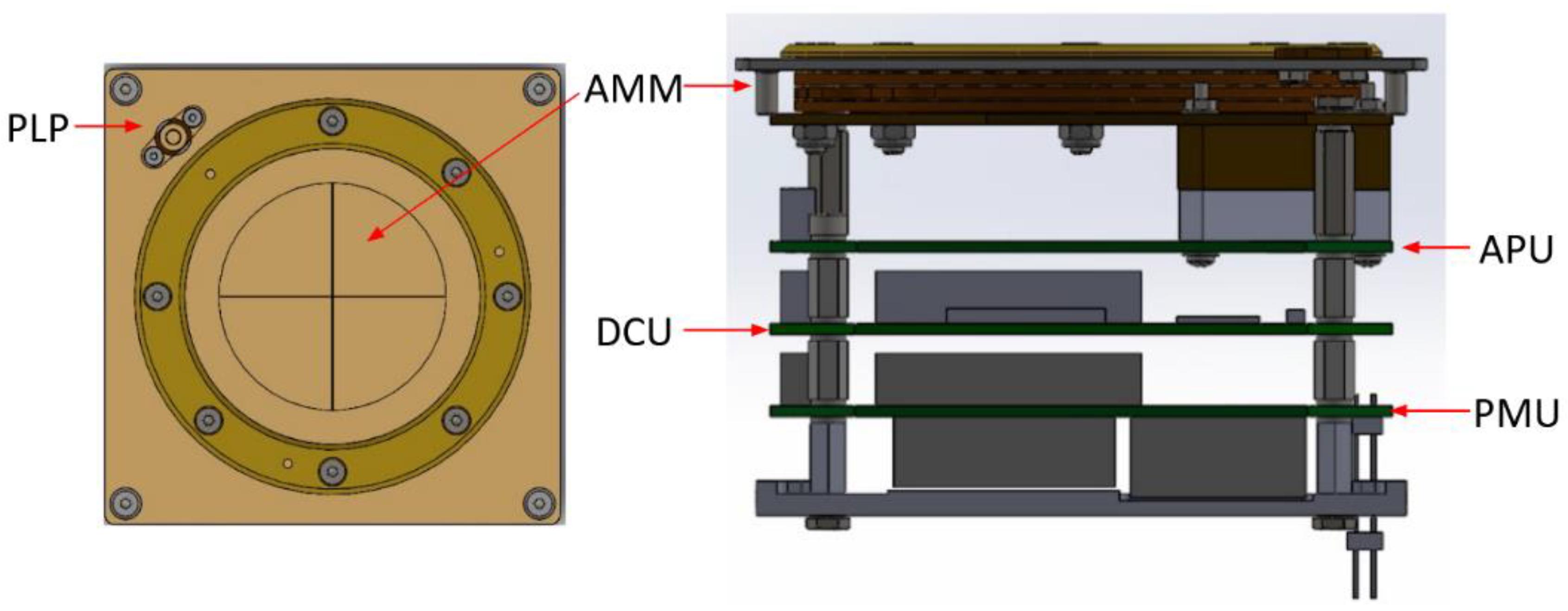
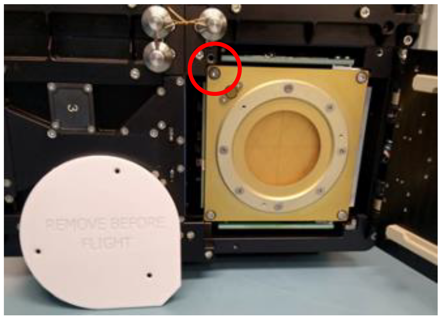
2.2. Payload: Compact Ionospheric Probe (CIP)
- AMM: A sensor for measuring plasma, which converts the measured variable into a voltage/current signal.
- APU: Converts the analog voltage/current of the sensor into a digital signal.
- DCU: Controls all of the analog to digital converters (ADCs) and digital to analog converters (DACs) of the APU. It monitors the temperature of CIP circuit boards and communicates with CDH.
2.3. Spacecraft Flight Software (FSW)
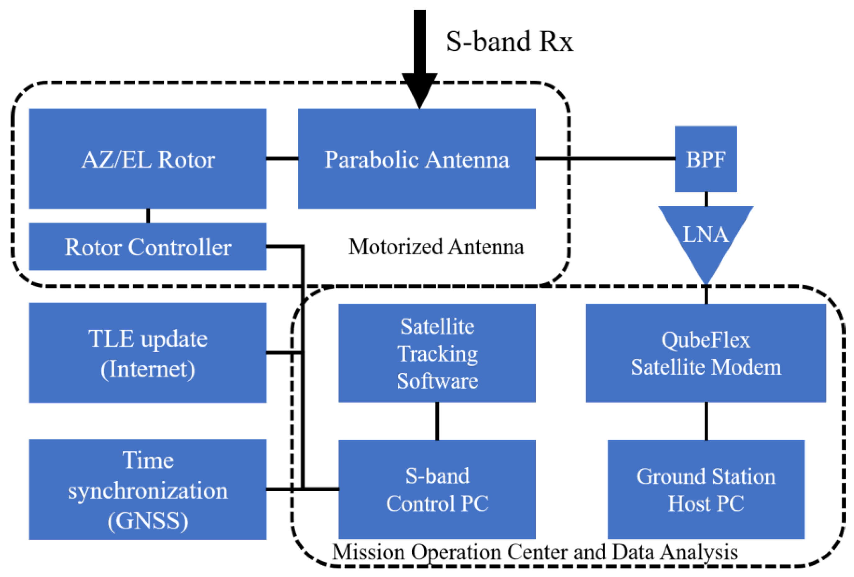
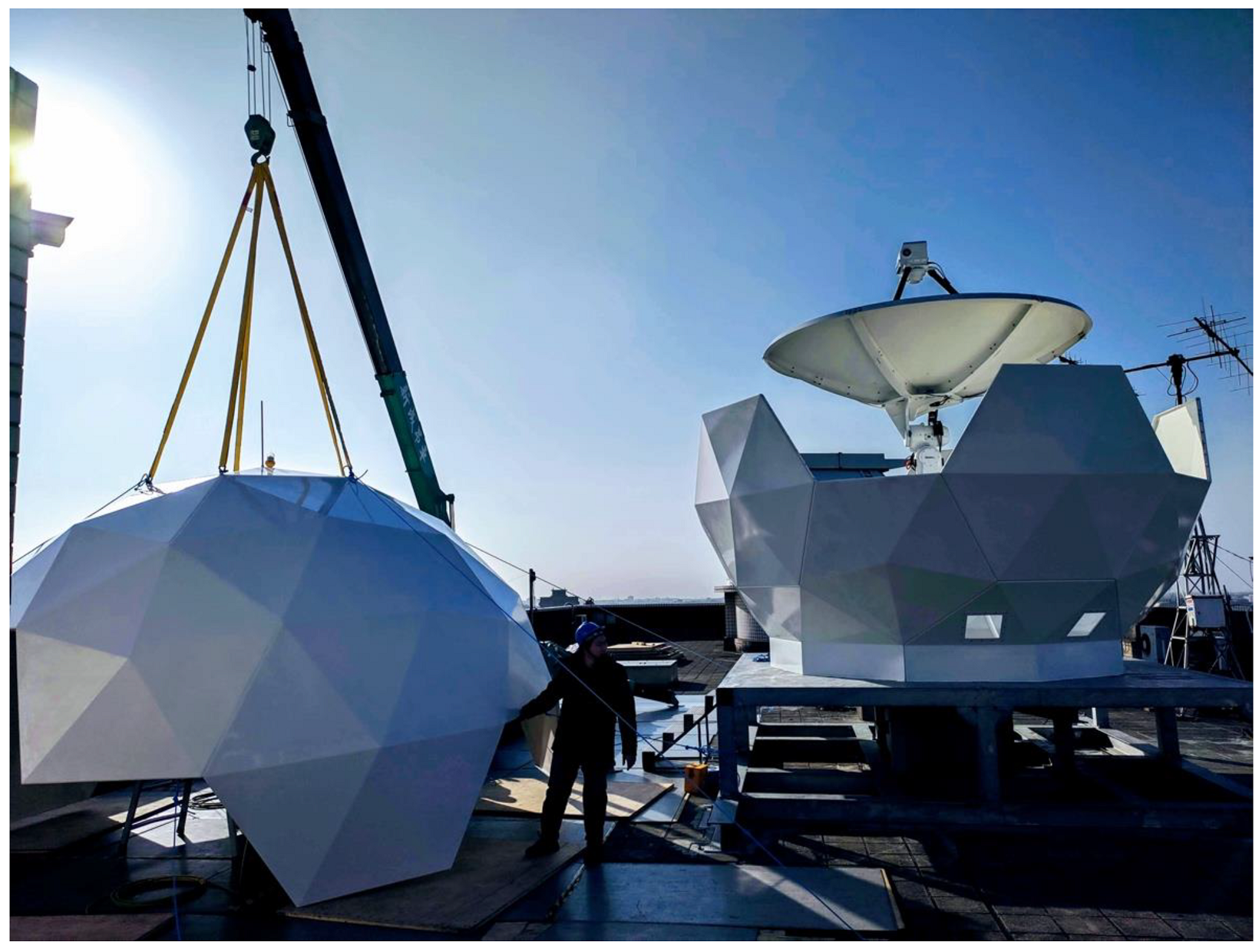
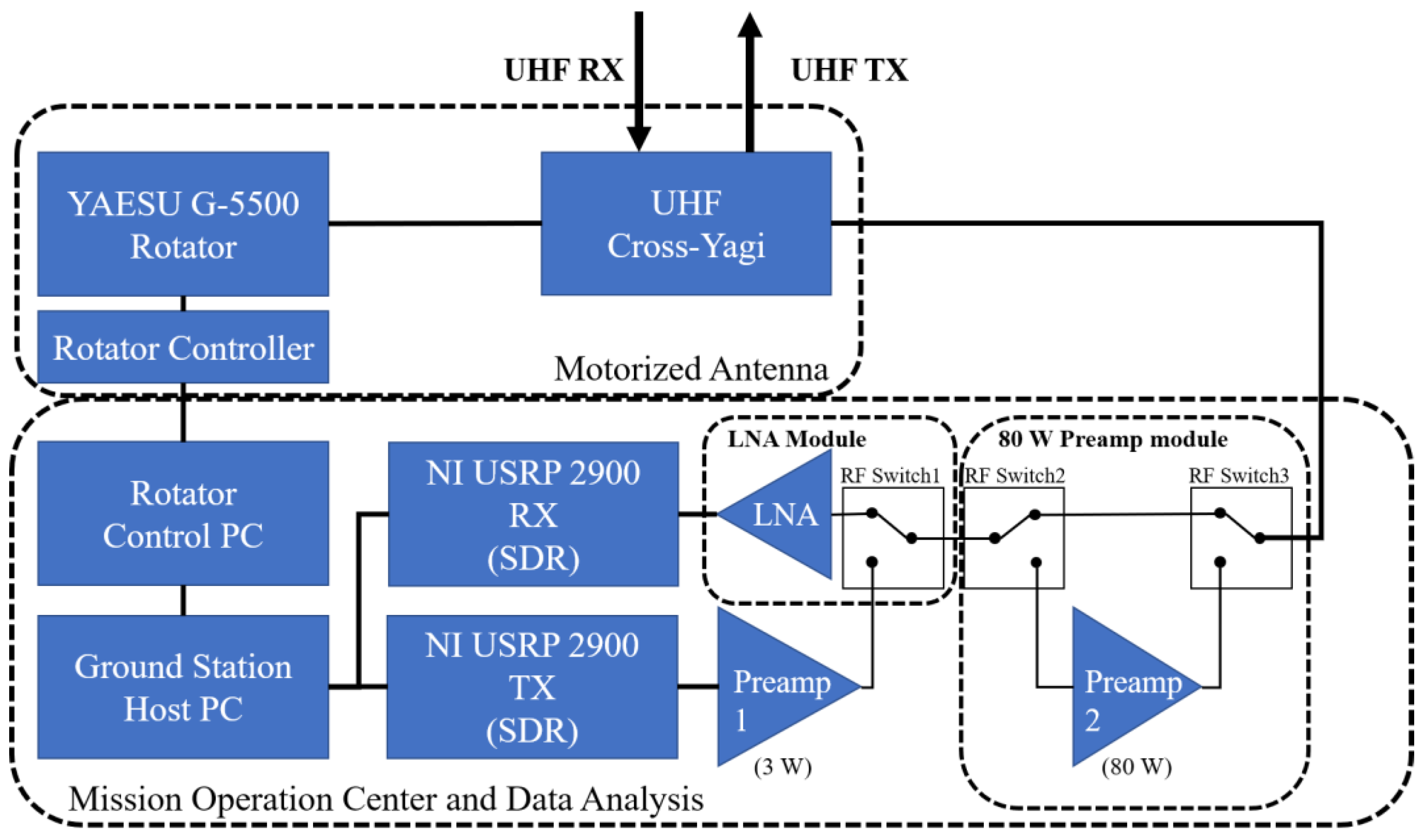
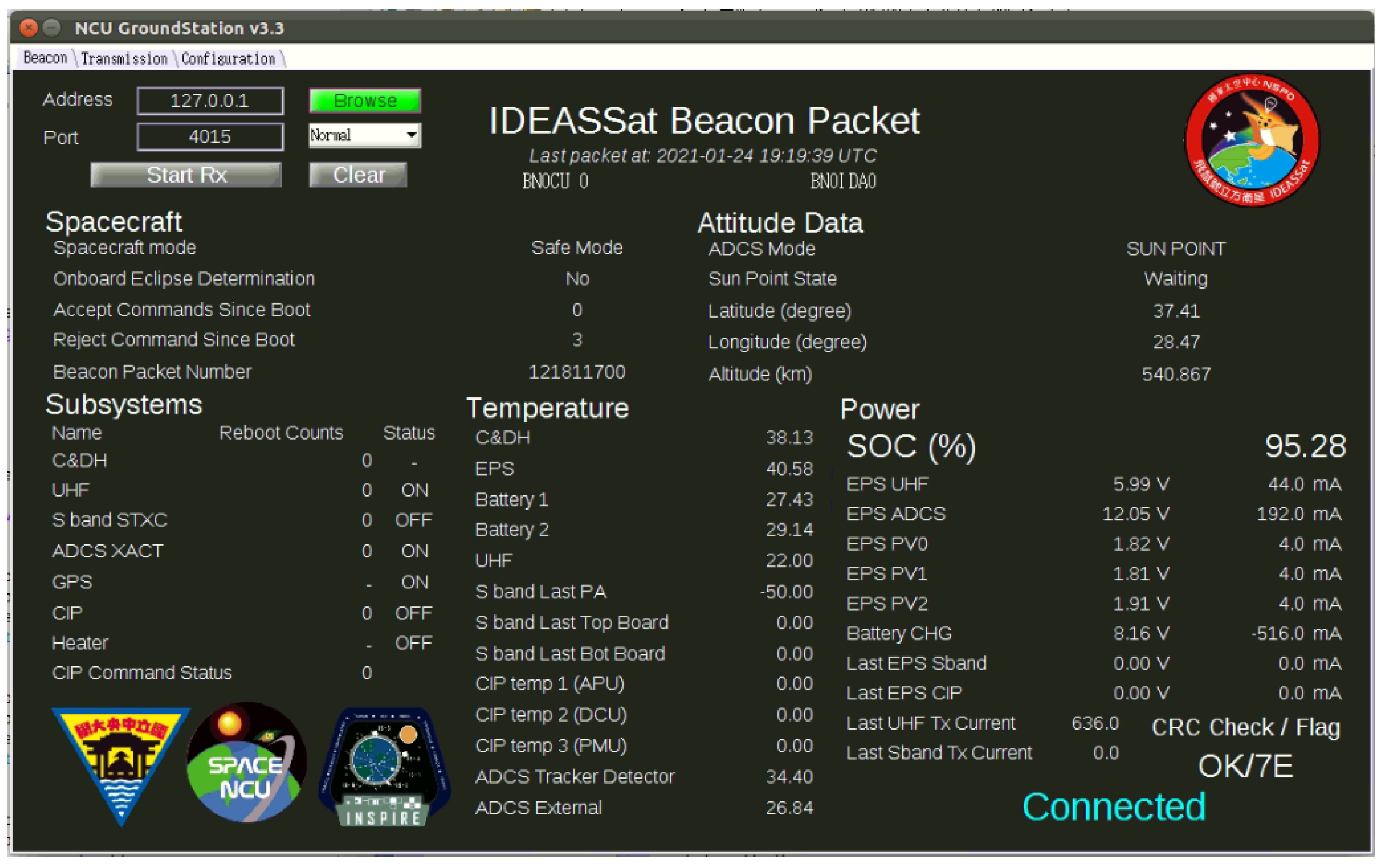
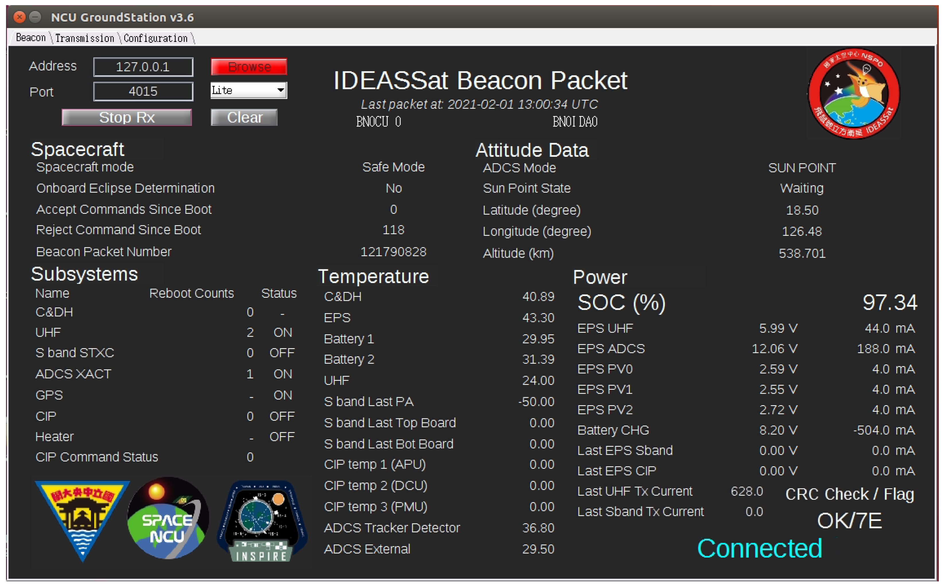
2.4. Ground Station
2.4.1. S-Band Ground Station
2.4.2. UHF Ground Station
2.5. Environmental and Functional Test
2.5.1. Flatsat
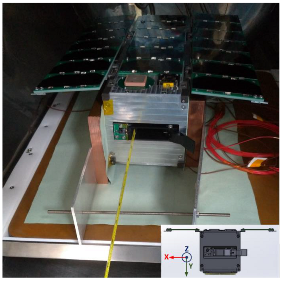
2.5.2. End-to-End Test
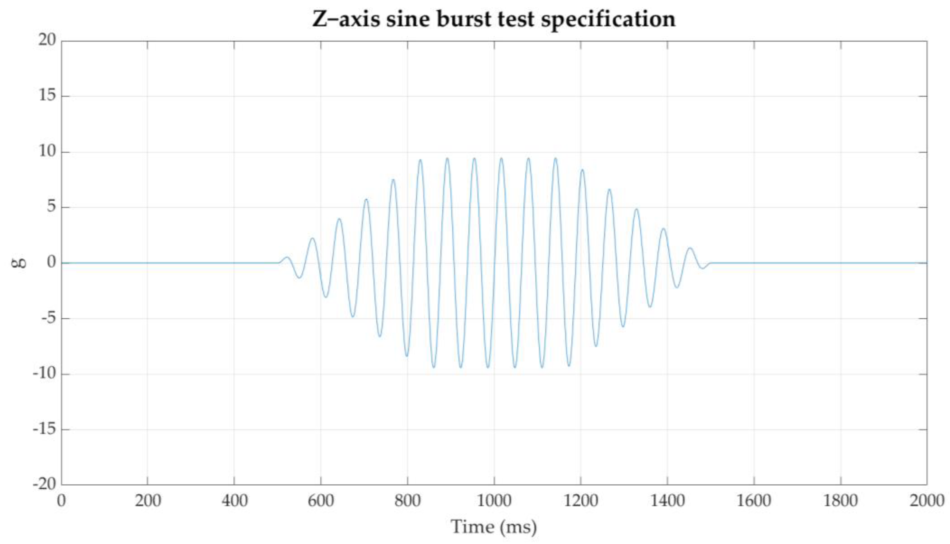
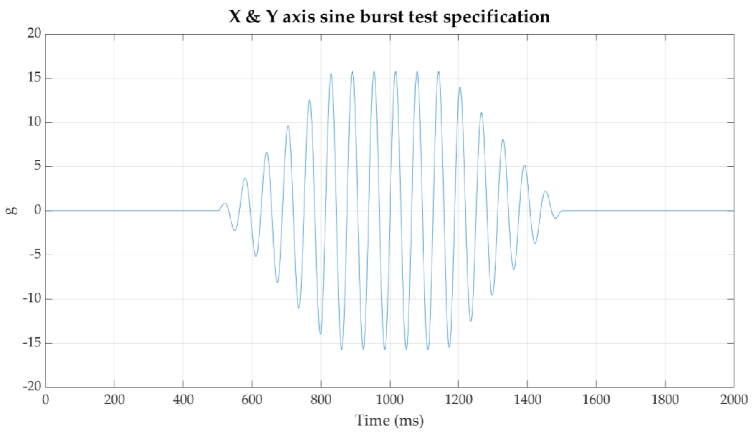
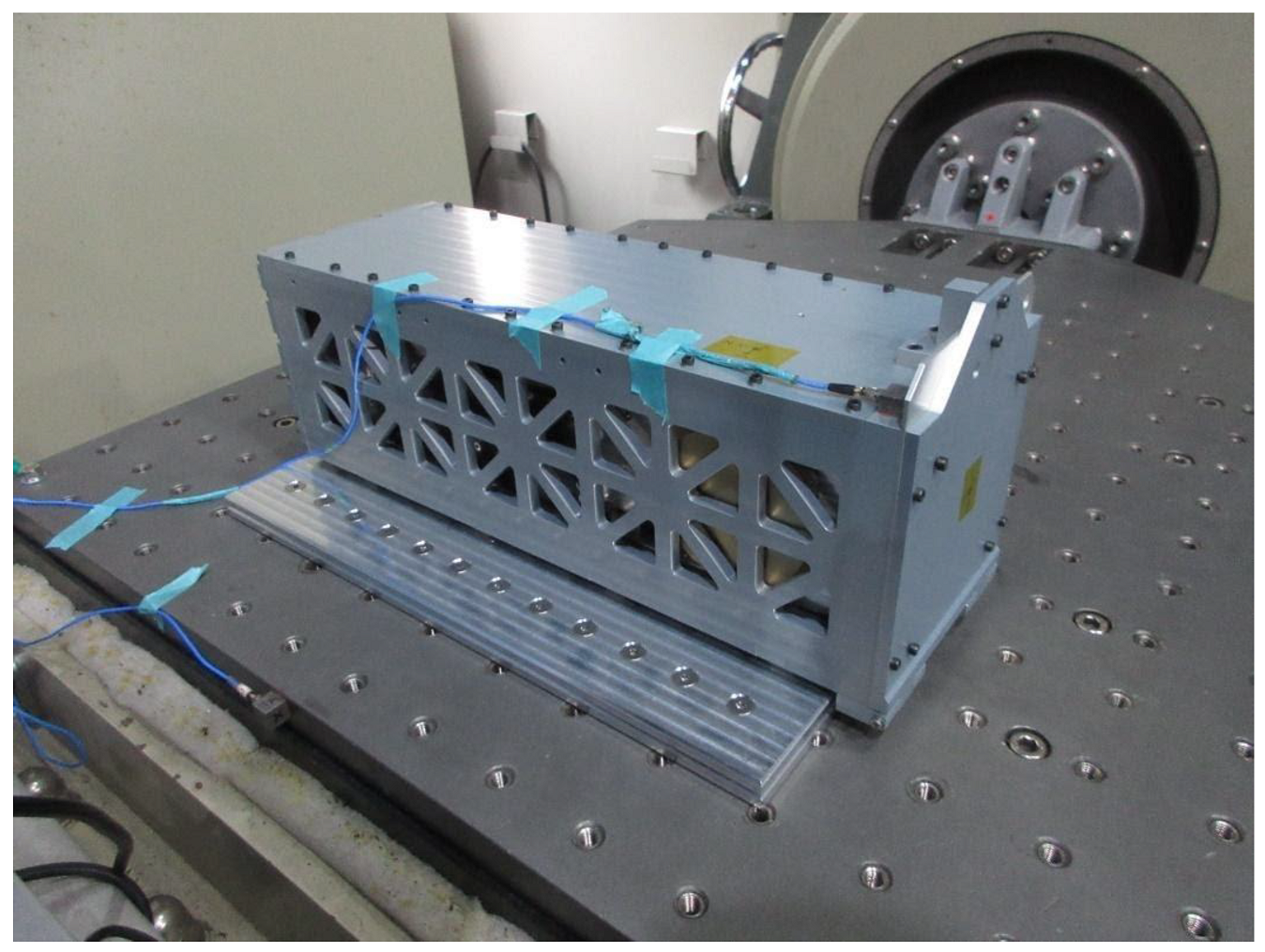
2.5.3. Vibration Test
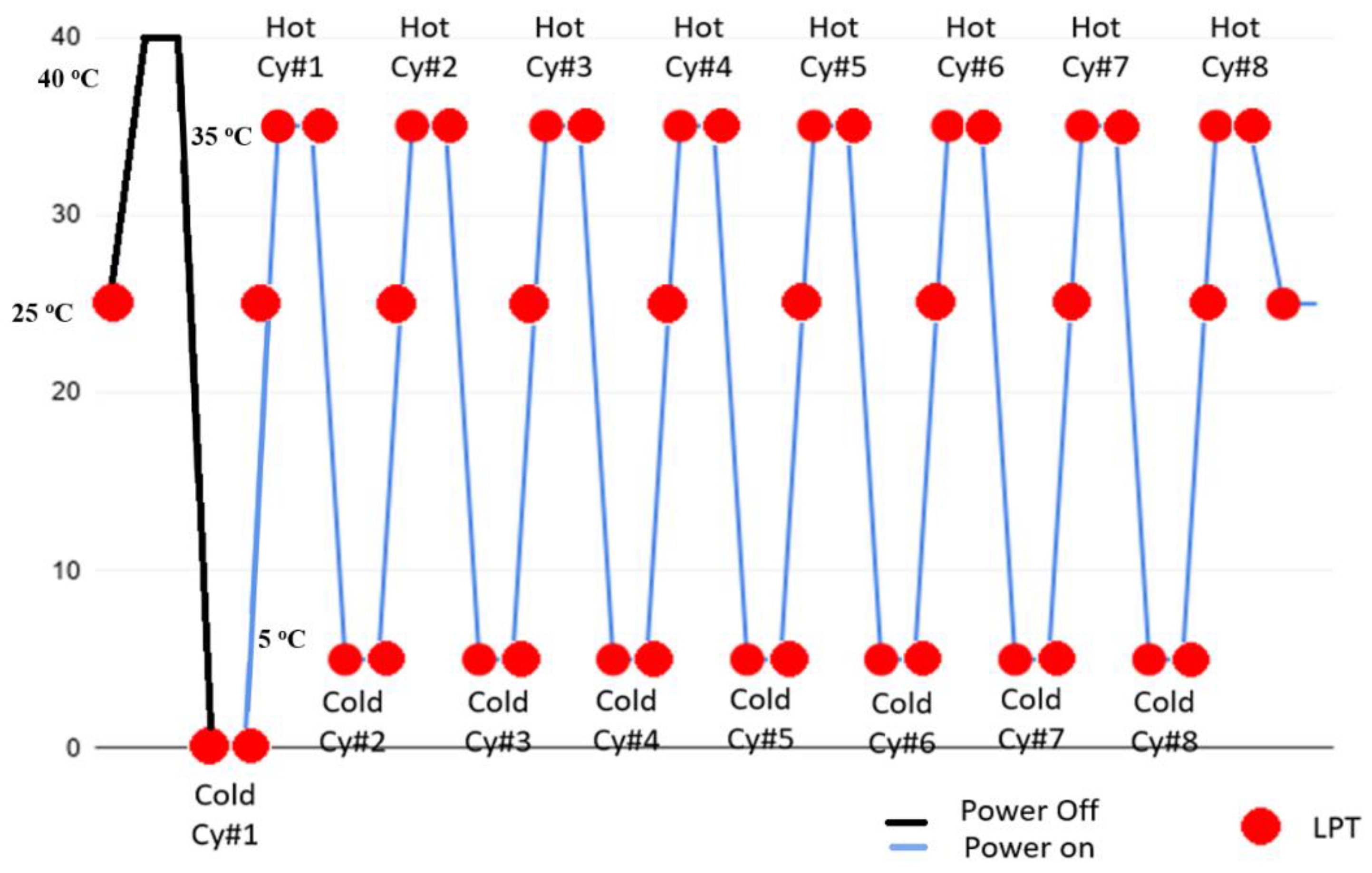
2.5.4. Thermal Vacuum Cycling Test (TVCT)
2.6. Delivery, Launch Vehicle Integration, and Launch
3. On Orbit Operations and Anomaly Analysis
3.1. Apparent Single Event Effect
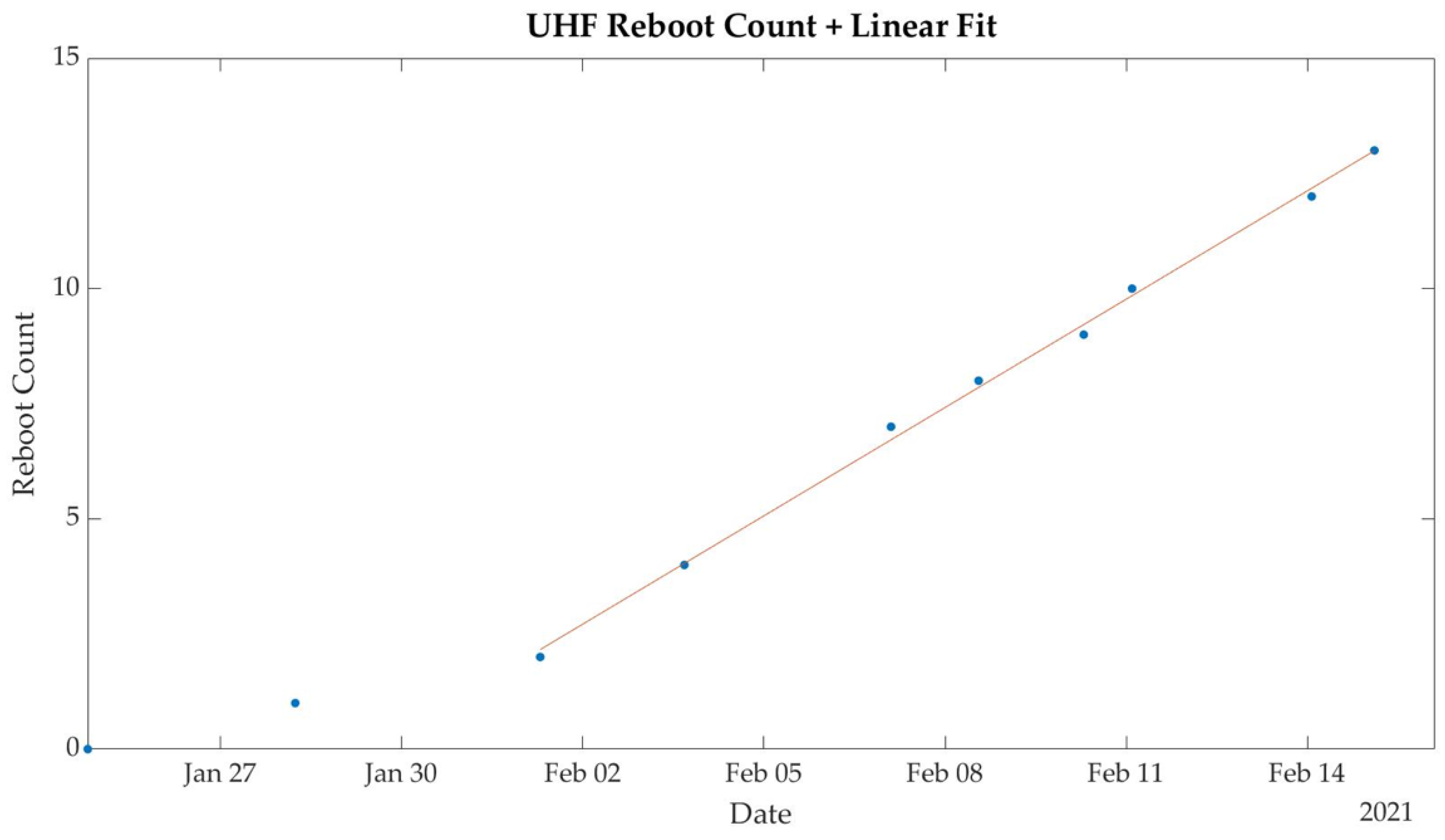
3.2. UHF Communication Anomalies
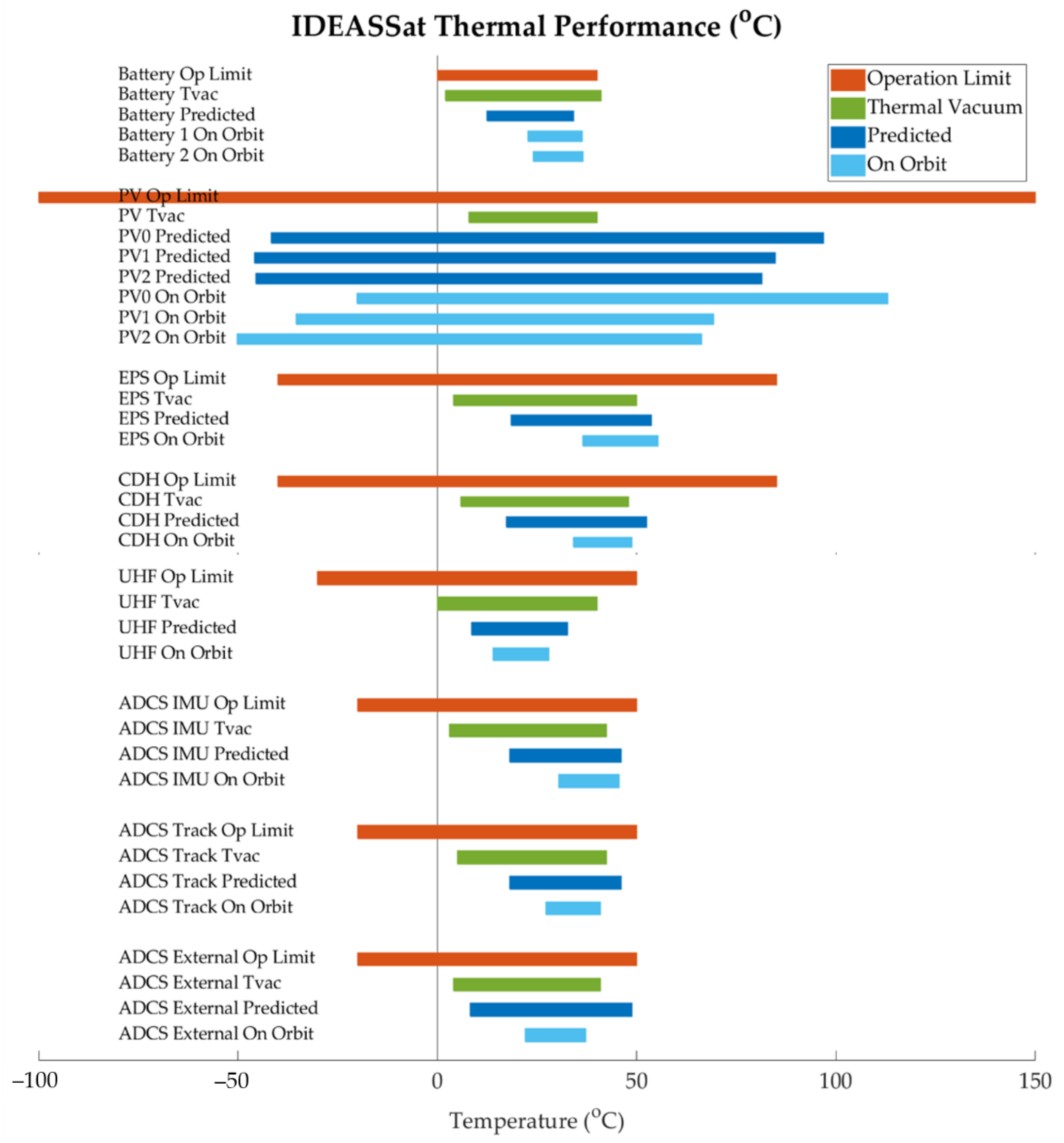
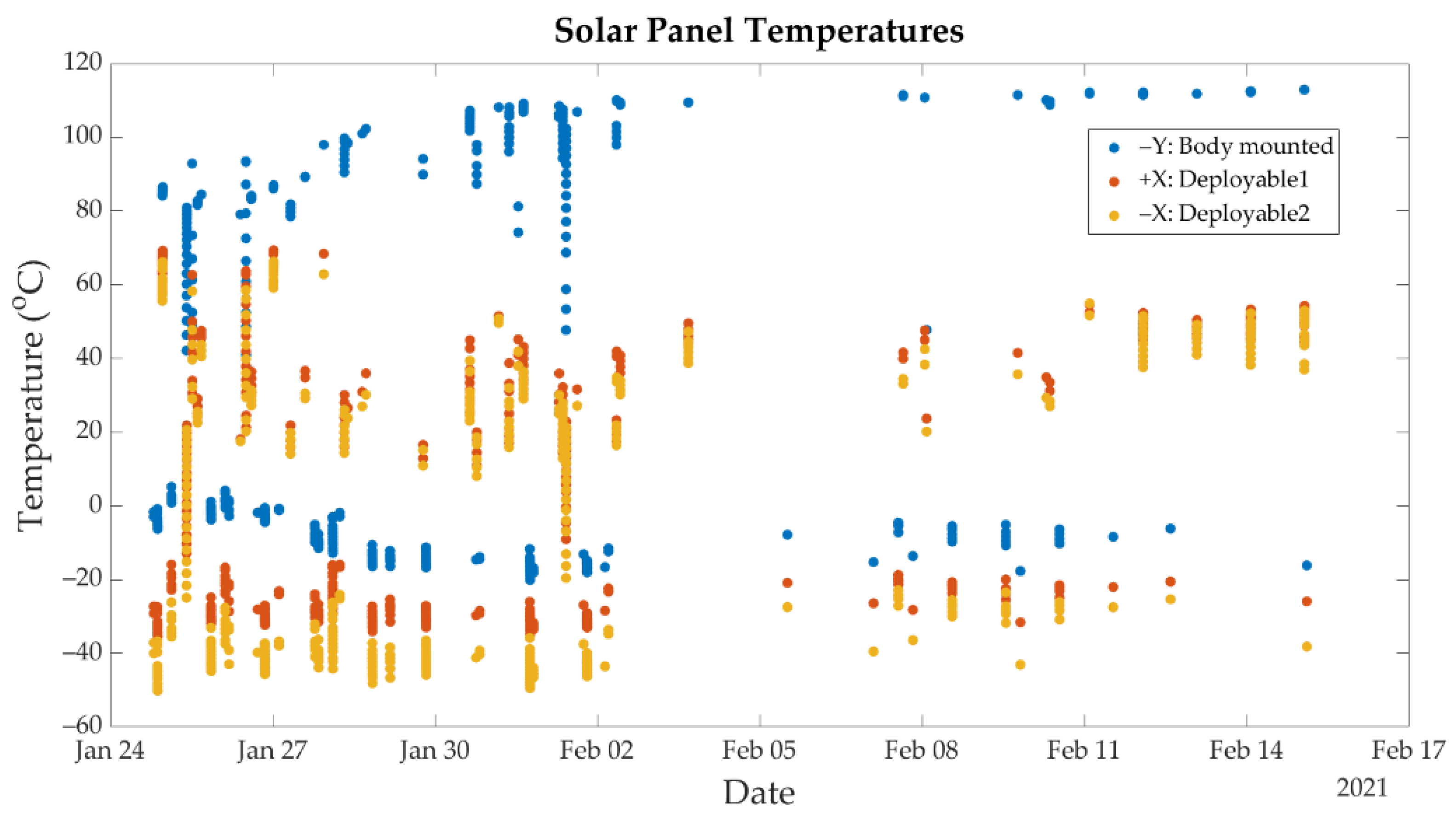
3.3. Thermal Performance
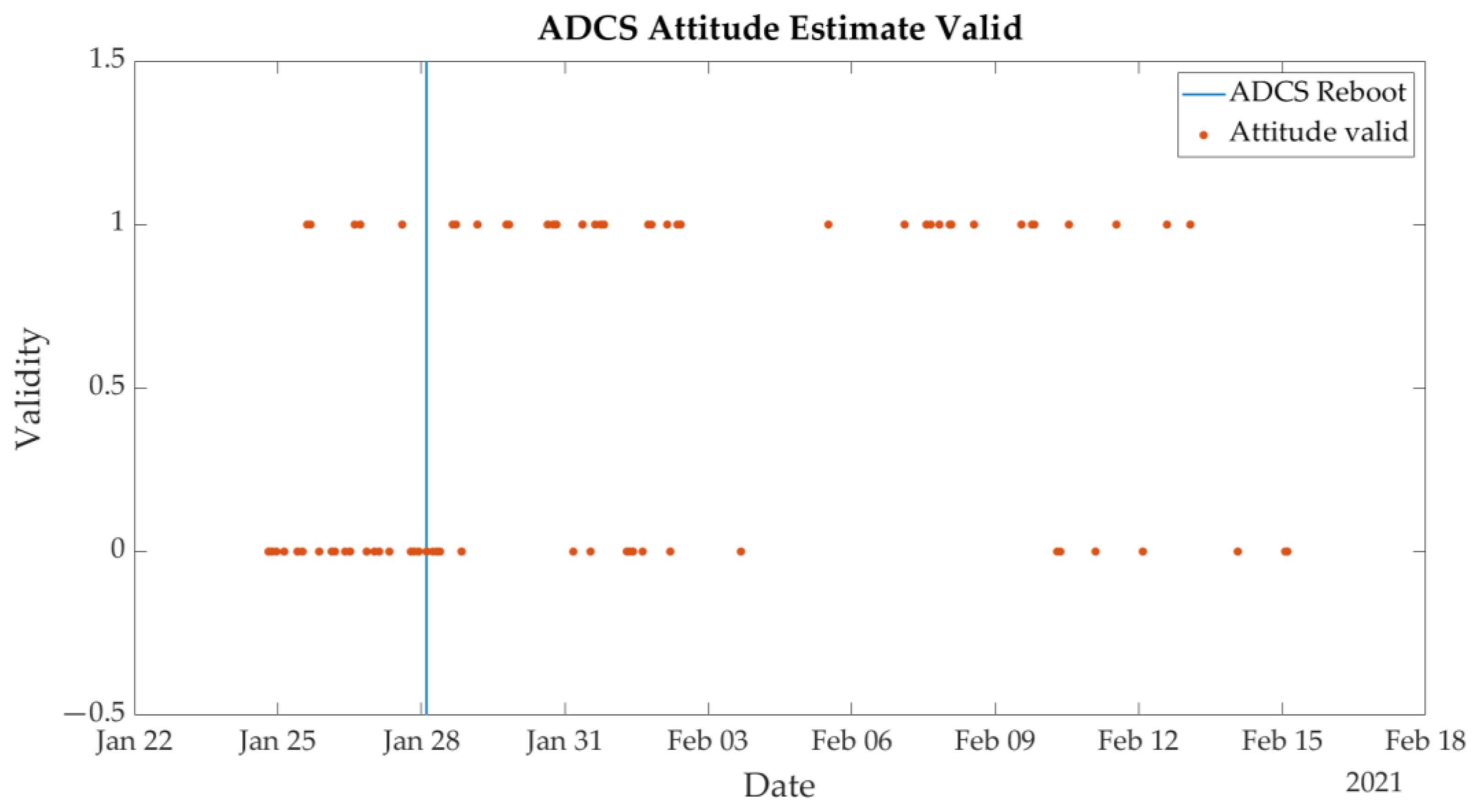
3.4. ADCS Reboot
3.5. Critical Anomaly–Loss of Communication
- FSW was not operating and logging data during the blackout, indicating that the spacecraft was likely powered off for the 1.5 month interval. As observed previously during the impedance mismatch anomaly on the ground, FSW would continue to function even in the event of a transceiver anomaly.
- The subsystem reset counters in flight data were reset, indicating that a power cycle and FSW reboot had taken place. However, there was no record of commanded reboots of the spacecraft by FSW, indicating that the power cycle and reboot were un-commanded.
- The 1.5-month blackout time, as opposed to a commanded or watchdog reboot, which would be completed within seconds.
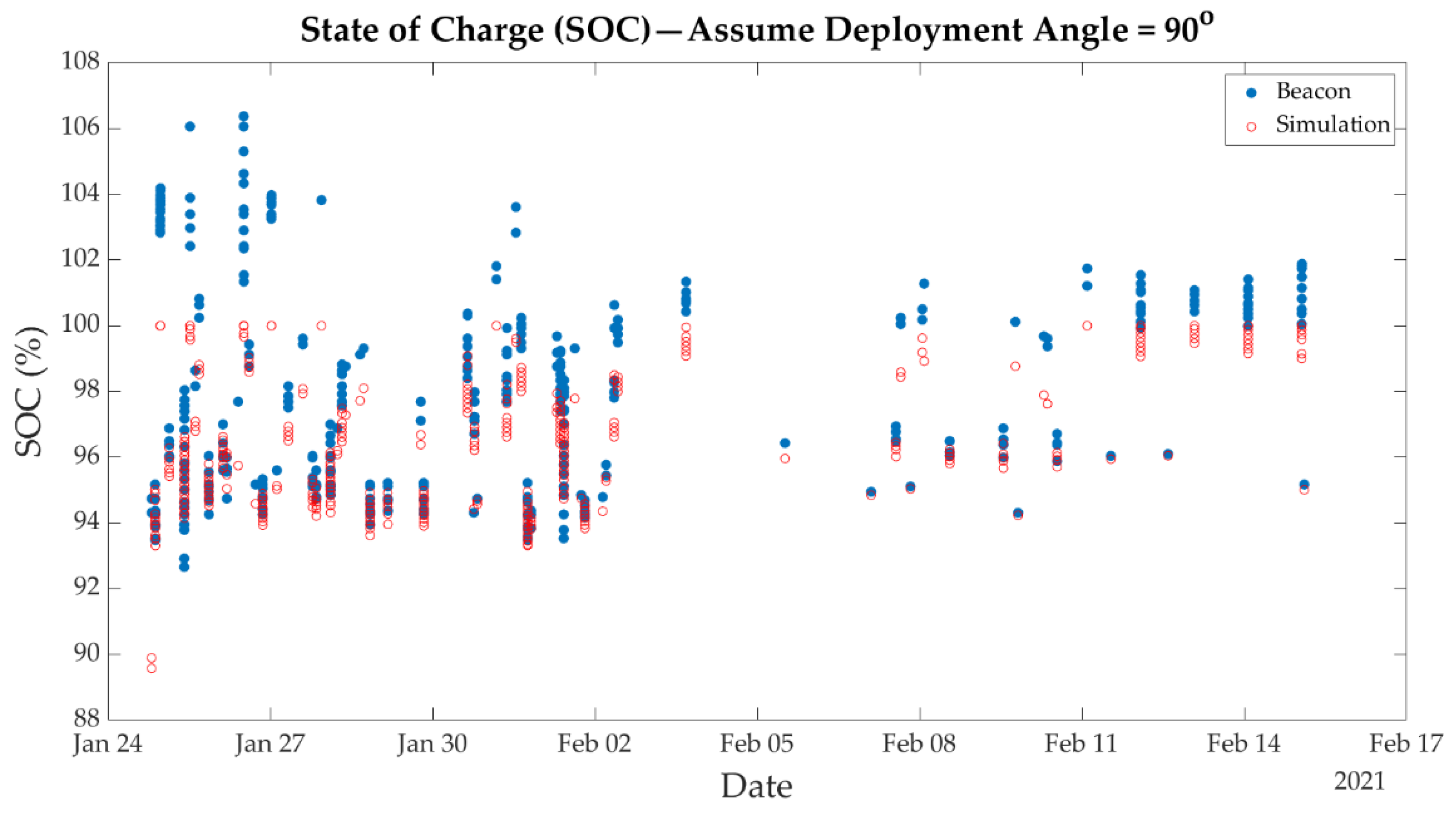
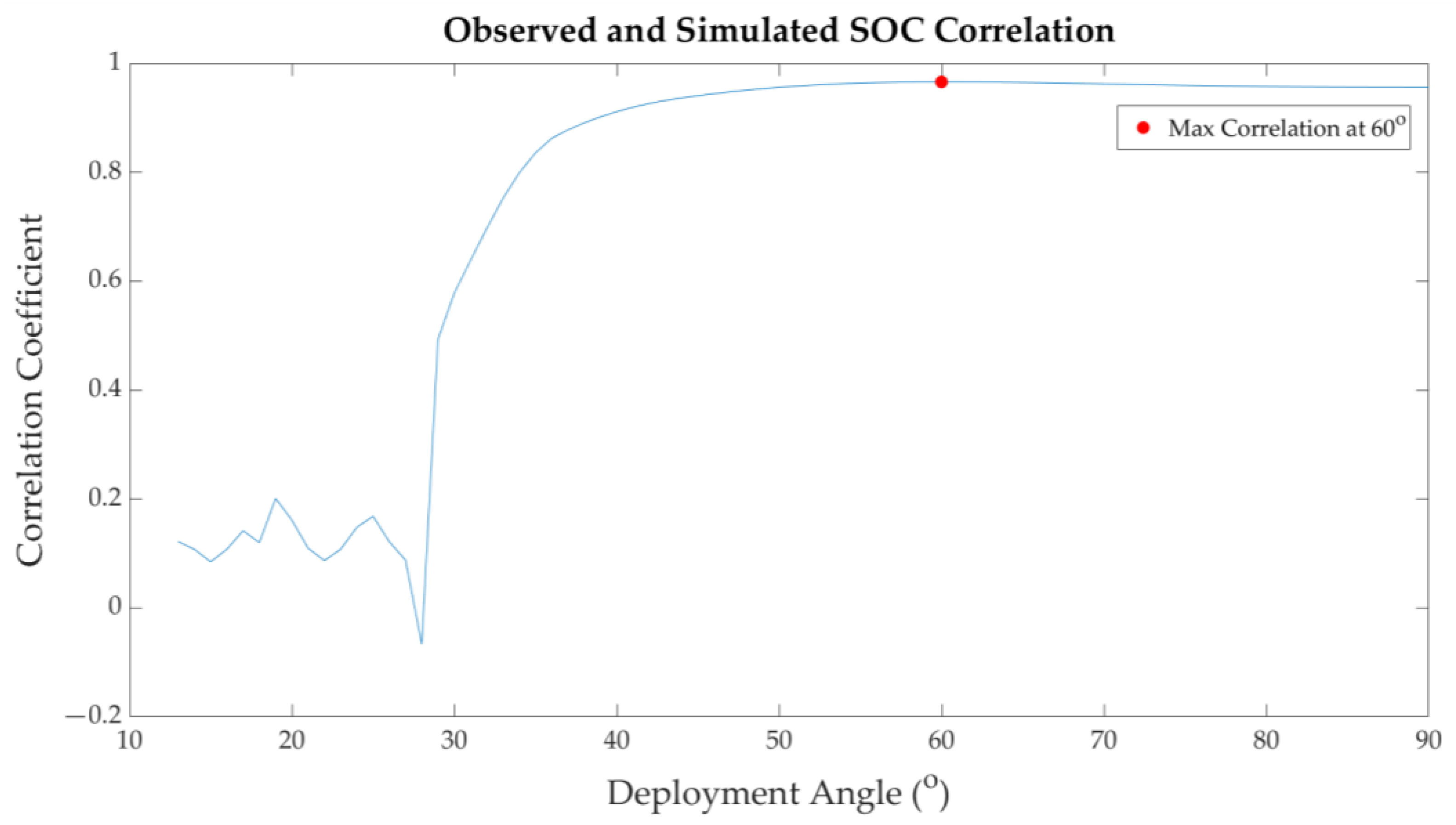
- The first beacon packet received following the blackout showed an SOC of 85%, which was much lower than that observed during the first 22 days of operation. This suggests the possibility of reboot through full or deep battery discharge.
- The second blackout after three days of operation.
4. Conclusions
- At both a system and subsystem level, many bugs and faults are more easily detected and identified after prototyping and testing. Rapid design, fabrication, testing, and revision of self-developed subsystems and flatsat construction should be commenced as early as possible in the project.
- COTS components or subsystems can be an effective method of resolving difficulties that cannot be handled in-house. It is critical to obtain a test report from the COTS manufacturer to cross compare with in-house test conditions and results, while also understanding the operating conditions under which the COTS component will behave nominally.
- Issues with AX.25 header implementation and UHF antenna impedance matching could have been resolved in a more efficient manner had outside experts been consulted earlier. Some problems encountered during spacecraft development may require expertise that does not yet exist in-house. Although unconventional solutions can sometimes be devised, it is best to consult with experts to understand how to correctly implement accepted solutions.
- Battery voltages can show rapid fluctuations when various subsystems are switched on and off. This should be taken into account when designing FSW mode transition thresholds and conditions to prevent rapid shifts in operating mode.
- Given the number of components comprising a spacecraft and the number of steps required for assembly, formulation of a complete step-by-step integration procedure is crucial to ensure successful integration. Inspection points should be clearly defined and listed to ensure all connectors and fasteners are properly staked and epoxied. These also need to be communicated to other teams responsible for fabricating other subsystems.
- Mechanical tolerances are critical to ensuring successful system integration, as well as interfacing with the launch vehicle. The spacecraft solar panel PCBs from the same manufacturer used on this mission were found to warp significantly with time, even after refabrication with increased PCB thickness. This should have served as a warning to seek an alternate provider, even if more expensive.
- FSW settings that persist following a power cycle should be used sparingly and with extreme caution. Measures should be taken to prevent corrupted settings from being logged, such as the implementation of ECC algorithms.
- SatNOGS is an invaluable resource for spacecraft tracking and monitoring, effectively providing worldwide coverage. Incorporating features to the beacon signal that will allow for the spacecraft state to be determined even without demodulation and decoding (e.g., directly from the received waterfall plots) is very useful for increased situational awareness. A successful example in the IDEASSat beacon signal was the use of different beaconing periods depending upon operational mode.
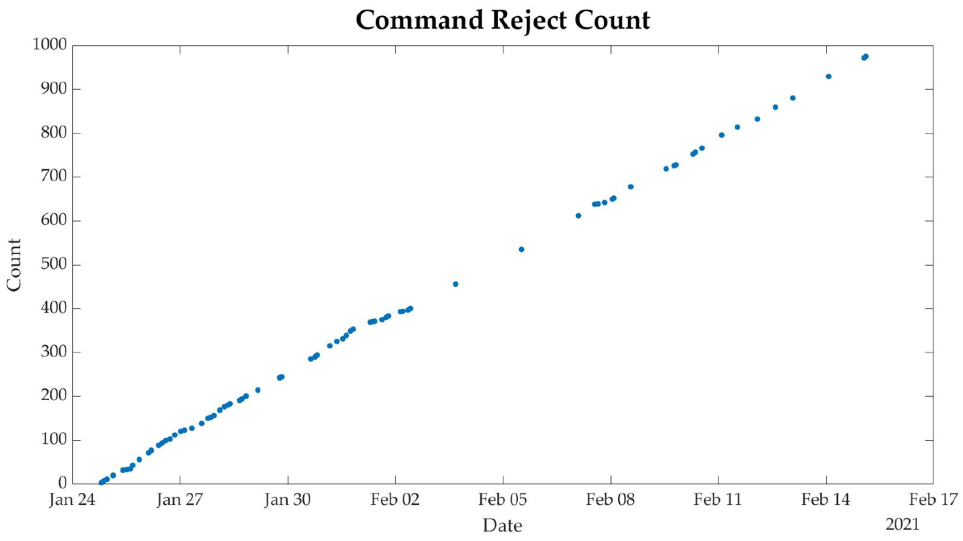
- A three-byte sync word was to distinguish uplinked commands from noise. However, this did not prevent cases of random noise from periodically matching the sync word, causing a persistent increase in the command reject count. A longer sync word might be considered in the future to reduce such anomalies.
- Some anomalies will only manifest after extended operation of the spacecraft. An example is the repeated UHF transceiver reboots, which did not manifest until T + 4 to T + 5 days. Longer duration burn-in tests of multiday duration on the ground could be helpful in identifying such anomalies on future missions.
- Ground stations, especially elements exposed to the elements, require routine maintenance and testing, especially considering that the free space loss on-orbit is much greater than that can be realistically attained without the use of attenuators during end-to-end tests on the ground. Routine tracking and reception of beacon signals from spacecraft already on-orbit will be helpful for functional testing of the ground station and its quality factor.
- While expensive, ionizing radiation tests for total ionizing dose and single event effects is still crucial for verifying the robustness of spacecraft avionics and validating the ability of the spacecraft to recover from single event effects. Power cycling recovery mechanisms need to be present for individual electrical circuits in the EPS, in addition to for other subsystems.
- Documentation and discussion of lessons learned during the development process and operational period are just as valuable as design reviews, ensuring that the experiences gained are passed on and applied to the development and improvement of future spacecraft systems and missions.
Author Contributions
Funding
Data Availability Statement
Acknowledgments
Conflicts of Interest
References
- Liu, J.; Chang, L.; Chao, C.; Chen, M.; Chu, Y.; Hau, L.; Huang, C.; Kuo, C.; Lee, L.; Lyu, L.; et al. The fast development of solar terrestrial sciences in Taiwan. Geosci. Lett. 2016, 3, 18. [Google Scholar] [CrossRef] [Green Version]
- Duann, Y.; Chang, L.; Chao, C.-K.; Chiu, Y.-C.; Tsai-Lin, R.; Tai, T.-Y.; Luo, W.-H.; Liao, C.-T.; Liu, H.-T.; Chung, C.-J. IDEASSat: A 3U CubeSat Mission for Ionospheric Science. Adv. Space Res. 2020, 66, 116–134. [Google Scholar] [CrossRef]
- Kunches, J. GNSS & Space Weather. Inside GNSS. 3 December 2007, pp. 30–36. Available online: https://www.insidegnss.com/auto/igm_Kunches.pdf (accessed on 9 February 2022).
- Space Weather Services, Bureau of Meteorology, Australian Government. Introduction to HF Radio Propagation. 2016. Available online: https://www.sws.bom.gov.au/Educational/5/2/2 (accessed on 1 February 2022).
- Frissell, N.; Miller, E.; Kaeppler, S.; Ceglia, F.; Pascoe, D.; Sinanis, N.; Smith, P.; Williams, R.; Shovkoplyas, A. Ionospheric Sounding Using Real-Time Amateur Radio Reporting Networks. Space Weather 2014, 12, 651–656. [Google Scholar] [CrossRef]
- Kelly, M.; Comberiate, J.; Miller, E.; Paxton, L. Progress toward forecasting of space weather effects on UHF SATCOM after Operation Anaconda. Space Weather 2014, 12, 601–611. [Google Scholar] [CrossRef]
- Lin, Z.; Chao, C.; Liu, J.; Huang, C.; Chu, Y.; Su, C.; Mao, Y.; Chang, Y. Advanced Ionospheric Probe scientific mission onboard FORMOSAT-5 satellite. Terr. Atmos. Ocean. Sci. 2017, 28, 99–110. [Google Scholar] [CrossRef] [Green Version]
- Baker, D.; Chandran, A. Space, still the final frontier. Science 2018, 361, 207. [Google Scholar] [CrossRef] [PubMed] [Green Version]
- Brown, C.D. Elements of Spacecraft Design; American Institute of Aeronautics and Astornautics, Inc.: Reston, VA, USA, 2002. [Google Scholar]
- AzurSpace. SPACE Assemblies. Available online: http://www.azurspace.com/index.php/en/products/products-space/space-assemblies (accessed on 1 February 2022).
- Mason, J.; Woods, T.; Chamberlin, P.; Moore, C.; Jones, A.; Kohnert, R.; Li, X.; Palo, S.; Solomon, S. Miniature X-Ray Solar Spectrometer: A Science-Oriented, University 3U CubeSat. J. Spacecr. Rocket. 2016, 53, 328–339. [Google Scholar] [CrossRef] [Green Version]
- Small Spacecraft Systems Virtual Institute, Ames Research Center, Moffett Field, California. NASA/TP—2020–5008734, State-of-the-Art, Small Spacecraft Technology. October 2020. Available online: https://www.nasa.gov/sites/default/files/atoms/files/soa2020_final7.pdf (accessed on 25 November 2021).
- AX.25 Link Access Protocol for Amateur Packet Radio, Version 2.2 Revision; Available online: http://www.ax25.net/AX25.2.2-Jul%2098-2.pdf (accessed on 25 November 2021).
- Microsemi. SmartFusion2 SoC. Available online: https://www.microsemi.com/product-directory/soc-fpgas/1692-smartfusion2 (accessed on 18 October 2021).
- Microsemi. DG0388 Demo Guide SmartFusion2 SoC FPGA Error Detection and Correction of eSRAM Memory. 2021. Available online: https://www.microsemi.com/document-portal/doc_download/131945-dg0388-smartfusion2-error-detection-and-correction-of-esram-memory-demo-guide (accessed on 16 November 2021).
- Microsemi. IGLOO2 and Smart Fusion2 65nm Commercial Flash FPGAs Interim Summary of Radiation Test Results. 21 October 2014. Available online: https://www.microsemi.com/document-portal/doc_download/134103-igloo2-and-smartfusion2-fpgas-interim-radiation-report (accessed on 25 November 2021).
- Microsemi. SmartFusion2 and IGLOO2 Neutron Single Event Effects (SEE) TR0020 Test Report. 1 April 2020. Available online: https://www.microsemi.com/document-portal/doc_download/135249-tr0020-smartfusion2-and-igloo2-neutron-single-event-effects-see-test-report (accessed on 25 November 2021).
- Microsemi. UG0331: SmartFusion2 Microcontroller Subsystem User Guide. 2018. Available online: http://www.microsemi.com/index.php?option=com_docman&task=doc_download&gid=130918 (accessed on 16 November 2021).
- Microsemi. UG0443 User Guide SmartFusion2 and IGLOO2 FPGA Security and Best Practices. 2019. Available online: https://www.microsemi.com/document-portal/doc_download/132037-ug0443-smartfusion2-and-igloo2-fpga-security-best-practices-user-guide (accessed on 16 November 2021).
- Chang, L.; Salinas, C.; Chiu, Y.-C.; Jones, M.; Rajesh, P.; Chao, C.-K.; Liu, J.-Y.; Lin, C.-H.; Hsiao, T.-Y. Implication of tidal forcing effects on the zonal variation of solstice equatorial plasma bubbles. J. Geophys. Res. Space Phys. 2021, 126, e2020JA028295. [Google Scholar] [CrossRef]
- Comtech Telecommunications Corp. Low/Medium Earth Orbit Satellite Tracking Antenna Systems. 2021. Available online: https://f.hubspotusercontent00.net/hubfs/51409/Comtech-MCT-October2019/Pdf/21_XY%20Brochure.pdf (accessed on 1 February 2022).
- Teledyne Paradaise Datacom. QubeFlex CubeSat/SmallSat/LEO Satellite Transceiver/Modem. 27 January 2022. Available online: http://www.teledynedefenseelectronics.com/paradisedatacom/Paradise%20Collateral/QubeFlex%20Datasheet%2020220127.pdf (accessed on 1 February 2022).
- Summers, T.; Schmandt, J.; Cheung, E.; Gentry, C.; Chen, Y. Cost effective, flexible ground architecture using software defined radio and GNU Radio. In Proceedings of the AIAA/USU Conference on Small Satellites, Logan, UT, USA, 4 – 9 August 2018. [Google Scholar]
- SpaceX. Rideshare Payload User’s Guide. November 2020. Available online: https://storage.googleapis.com/rideshare-static/Rideshare_Payload_Users_Guide.pdf (accessed on 6 October 2021).
- Monteiro, J.; Rocha, R.; Silva, A.; Afonso, R.; Ramos, N. Integration and Verification Approach of ISTSat-1 CubeSat. Aerospace 2018, 6, 131. [Google Scholar] [CrossRef] [Green Version]
- NASA Goddard Space Flight Center. Structural and Mechanical. In General Environmental Verification Standard (GEVS) for GSFC Flight Programs and Projects; NASA Goddard Space Flight Center: Greenbelt, MD, USA, 2005; pp. 2.4-1–2.4-27. [Google Scholar]
- NASA. Reliability Preferred Practice PT-TE-1420 Sine-Burst Load Test. February 1999. Available online: https://extapps.ksc.nasa.gov/Reliability/Documents/Preferred_Practices/1420.pdf (accessed on 2 February 2022).
- NASA. Reliability Preferred Practice PT-TE-1413 Random Vibration Testing. February 1999. Available online: https://extapps.ksc.nasa.gov/Reliability/Documents/Preferred_Practices/1413.pdf (accessed on 2 February 2022).
- ISISpace. TESTPOD. 2021. Available online: https://www.isispace.nl/product/testpod/ (accessed on 2 February 2022).
- NASA Goddard Space Flight Center. Thermal-Vacuum Qualification. In General Environmental Verification Standard (GEVS) for GSFC Flight Programs and Projects; NASA Goddard Space Flight Center: Greenbelt, MD, USA, 2005; pp. 2.6-1–2.6-12. [Google Scholar]
- ISISpace. QuadPack CubeSat Deployer. Available online: https://www.isispace.nl/product/quadpack-cubesat-deployer/ (accessed on 16 November 2021).
- Rupprecht, M. IDEASSAT Telemetry. 24 January 2021. Available online: https://www.satblog.info/ideasaat-spectrum/ (accessed on 16 November 2021).
- Baker, D.N. The Occurrence of Operational Anomalies in Spacecraft and Their Relationship to Space Weather. IEEE Trans. Plasma Sci. 2000, 28, 2007–2016. [Google Scholar] [CrossRef]
- SatNOGS. Observation #3636486. 15 February 2021. Available online: https://network.satnogs.org/observations/3636486/ (accessed on 19 November 2021).
- SatNOGS. Observation #3876617. 2 April 2021. Available online: https://network.satnogs.org/observations/3876617/ (accessed on 3 December 2021).
- Scheick, L. Testing Guideline for Single Event Gate Rupture (SEGR) of Power MOSFETs, NASA. February 2008. Available online: https://trs.jpl.nasa.gov/handle/2014/40764 (accessed on 3 December 2021).
- NASA. EEE-INST-002: Instructions for EEE Parts Selection, Screening, Qualification, and Derating. May 2003. Available online: https://nepp.nasa.gov/index.cfm/12821 (accessed on 3 December 2021).
- Baumann, R.; Kruckmeyer, K. Radiation Handbook for Electronics. 4 June 2014. Available online: https://www.ti.com/seclit/eb/sgzy002a/sgzy002a.pdf (accessed on 3 December 2021).
- Sinclair, D.; Dyer, J. Radiation Effects and COTS Parts in SmallSats. In Proceedings of the AIAA/USU Conference in Small Satellites, Logan, UT, USA, 14 August 2013. [Google Scholar]


| Subsystem | Solution | TRL |
|---|---|---|
| ADCS | Blue Canyon Technologies XACT-15 with NovAtel OEM-719 GPS Receiver | 9 |
| COMM (UHF) | SpaceQuest TRX-U Transceiver UHF Tape Measure Antenna * | 9 9 |
| COMM (S-band) | CPUT STX-C Transmitter CPUT Cubesat S-Band TX Patch Antenna | 9 9 |
| EPS | NCU EPS Controller Board * Li-Ion Battery Module * AzurSpace TJ Solar Cell Assembly 3G30A Solar Panel PCB * | 8 9 9 9 |
| CDH | Microsemi Smartfusion2 System-On-Module NCU CDH Interface Board * | 9 9 |
| FSW | IDEASSat Flight Software * | 9 |
| STR | NCU 3U Bus * | 9 |
| TCS | Thin Film Battery Heater * Passive Thermal Conduction Pathways * | 9 9 |
| Payload | Compact Ionospheric Probe * | 8 |
| Subsystem | Input Voltage (V) | Power (W) |
|---|---|---|
| ADCS | 12 | 6.74 |
| GPS Receiver | 3.3 | 1.8 |
| CDH | 3.3 | 1.4 |
| UHF Tx/Rx | 6 | 10/0.2 |
| S-Band Tx/Stand-by | Battery Voltage | 5/0.6 |
| CIP | 12 | 3.5 |
| Beacon Type | Beacon Size (Byte) | Description |
|---|---|---|
| Lite | 360 | Normal packet split into 9 consecutive 40-byte packets (default). |
| Normal | 204 | Format similar to AX.25. Content includes housekeeping data. |
| Short | 48 | The short version, only includes critical state of health data. |
| Protocol | Implementation | Number |
|---|---|---|
| I2C | RTC/S-band/EPS | 3 |
| SPI | Micro SD card/S-band | 3 |
| UART | GSE/ADCS/UHF/CIP | 5 |
| Instrument | Plasma Parameters |
|---|---|
| Planar Langmuir Probe (PLP) | Electron temperature |
| Ion Trap (IT) | Ion density |
| Retarding Potential Analyzer (RPA) | Light/heavy ion mass ratio Ion temperature Ion ram speed |
| Ion Drift Meter (IDM) | Ion arrival angles |
| Major Mode | Sub-Modes |
|---|---|
| Emergency | Phoenix mode, Safe mode |
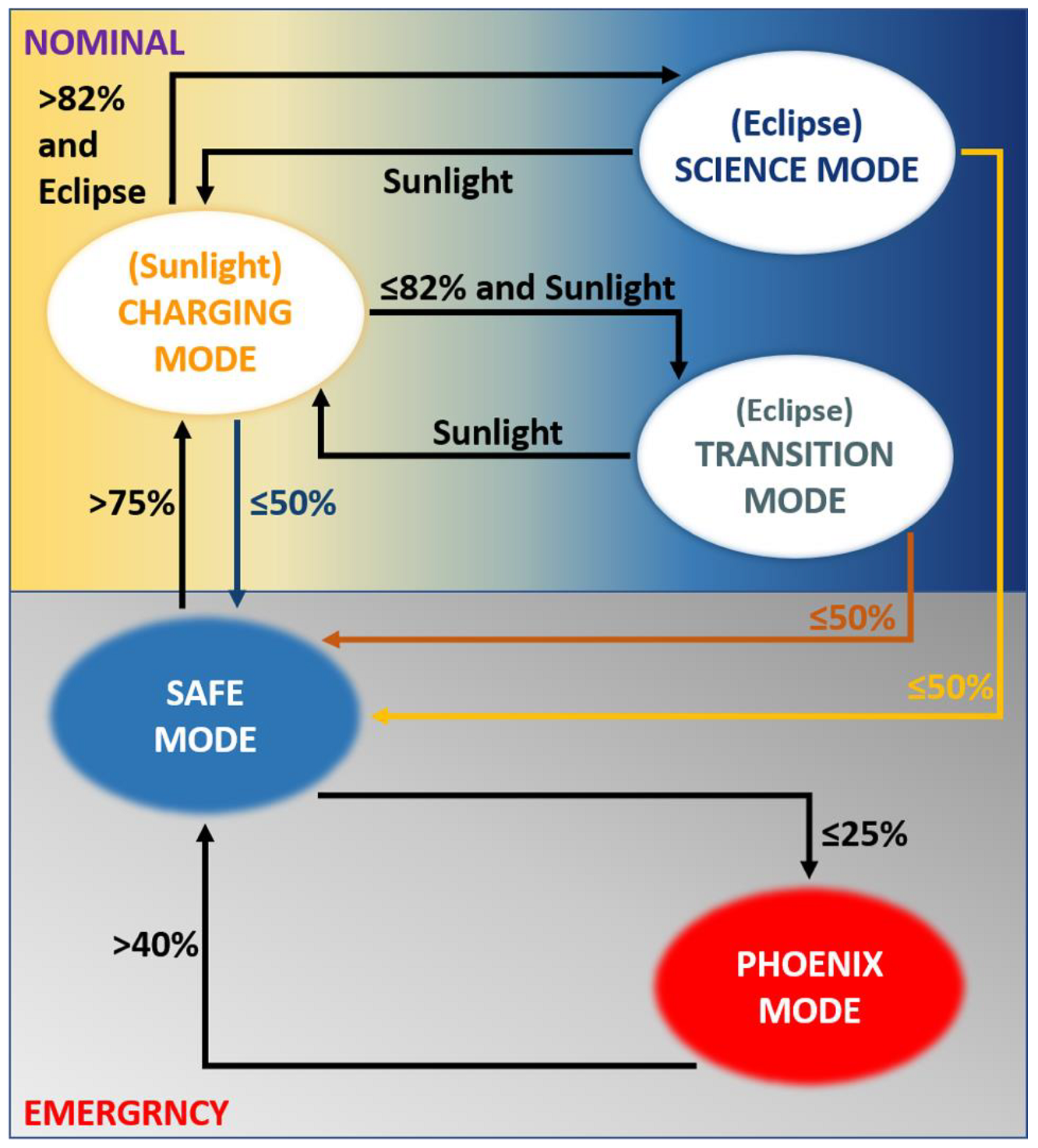
| Nominal | Charging mode, Transition mode, Science mode |
| Subsystems | PHOENIX | SAFE | CHARGING | SCIENCE |
|---|---|---|---|---|
| EPS | ON | ON | ON | ON |
| CDH | ON | ON | ON | ON |
| UHF | ON | ON | ON | ON |
| ADCS | OFF | ON (Sun Point) | ON (Fine Reference Point) | ON (Fine Reference Point) |
| S-Band | OFF | On Command | On Command | OFF |
| CIP | OFF | OFF | OFF | ON |
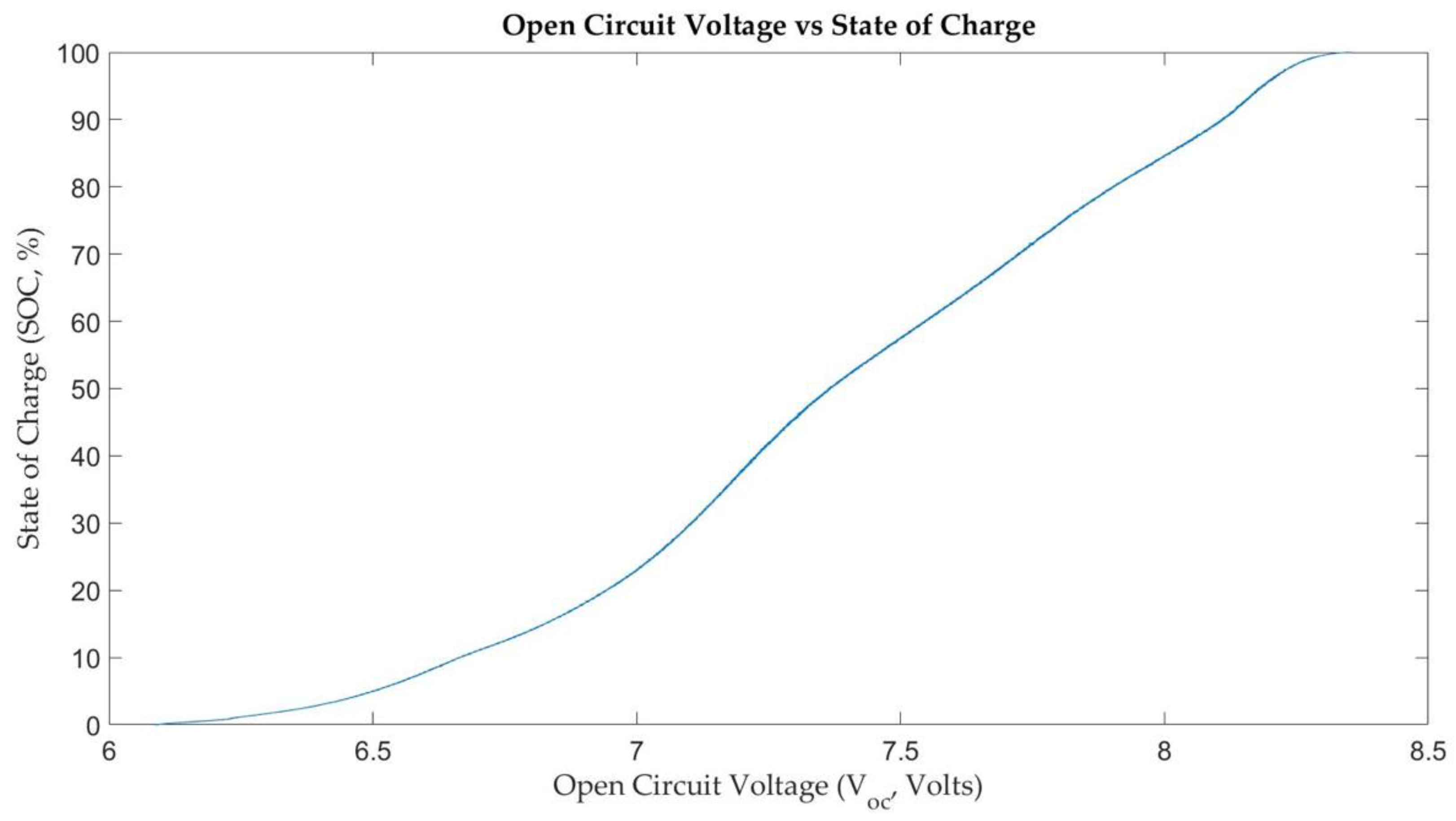
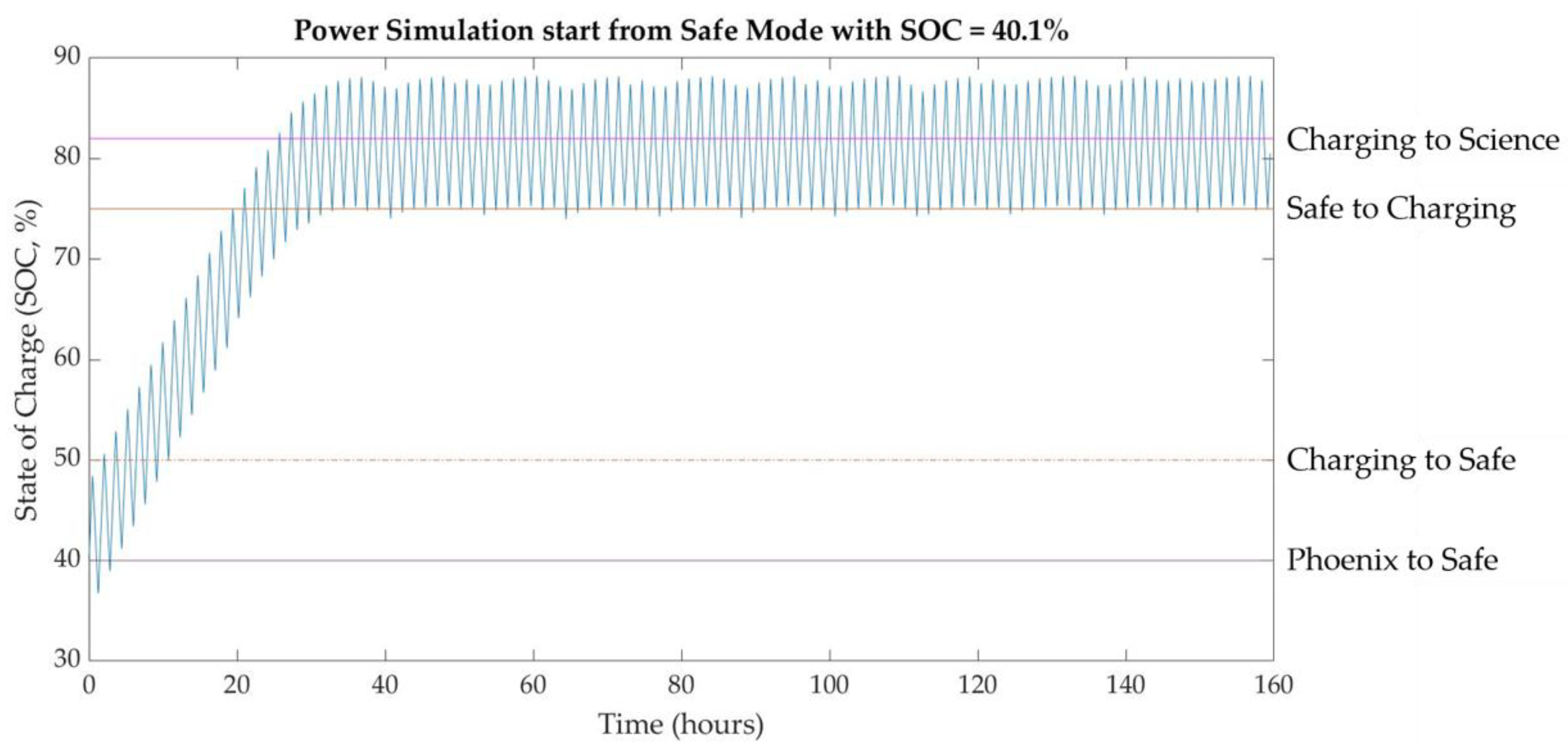
| Mode Transition | SOC (%) | Vop | Actions on Transition |
|---|---|---|---|
| Safe to Phoenix | 25 | 7.0 | Beacon period set to 60 s. |
| Phoenix to Safe | 40 | 7.2 | Turn on ADCS. Beacon period set to 30 s. |
| Charging to Safe | 50 | 7.4 | ADCS to coarse sun pointing. |
| Transition to Safe | 50 | 7.4 | ADCS to coarse sun pointing. |
| Science to Safe | 50 | 7.4 | Turn off CIP. ADCS to coarse sun pointing. |
| Safe to Charging | 75 | 7.8 | ADCS to fine reference sun pointing. |
| Charging to Science | 82 | 8 | Turn on CIP. ADCS to LVLH. |
| Science to Charging | - | - | Triggered by transition from eclipse to sunlight. ADCS to fine reference sun pointing. |
| Charging to Transition | <82 | 8 | ADCS to LVLH. |
| Transition to Charging | - | - | Triggered by transition from eclipse to sunlight. ADCS to fine reference sun pointing. |
| Beacon Format | Short | Lite | Normal |
|---|---|---|---|
| Full Packet Loss (%) | 0 | 0 | 0 |
| Partial Packet Loss (%) | - | 50 | - |
| Packet Error (%) | 56.5 | 100 | 100 |
| Band | Power Spectral Density (g2 Hz−1) |
|---|---|
| 20 Hz | 0.0088 |
| 100 Hz | 0.0088 |
| 300 Hz | 0.0252 |
| 600 Hz | 0.0252 |
| 740 Hz | 0.07 |
| 850 Hz | 0.07 |
| 2000 Hz | 0.01288 |
| GRMS | 7.75 g |
| Duration | 1 min |
| Date | Satellite Operation | Ground Station Operation |
|---|---|---|
| 2021-01-25 | Safe mode. | Flight data downlink from SatNOGS. Anomaly: NCU ground station unable to receive beacon. |
| 2021-01-26 | Safe mode. | Flight data downlink from SatNOGS. NCU ground station servicing start. |
| 2021-02-01 | Safe mode. | NCU ground station servicing complete. Flight data downlink from NCU ground station and SatNOGS. |
| 2021-02-02 | Safe mode. Anomaly: Autonomous beacon format change into Normal mode. | Flight data downlink from NCU ground station and SatNOGS. |
| 2021-02-15 | Anomaly: COMM blackout. | No signal received at NCU ground station and SatNOGS. |
| 2021-02-25 | Anomaly: COMM blackout. | UHF SDR power output found to be insufficient to drive primary UHF amplifier at NCU ground station. Preamplifier added. |
| 2021-03-03 | Anomaly: COMM blackout. | Ground station Tx power verified to be nominal following preamplifier installation. |
| 2021-04-02 | Safe mode. Beacon Tx resumes. Beacon is changed into Lite mode after receiving command. | Commanded IDEASSat to replay saved flight data. Commanded IDEASSat to change beacon format to Lite. Flight data downlink from NCU ground station and SatNOGS. |
| 2021-04-04 | Anomaly: COMM blackout. | No signal received at NCU ground station and SatNOGS. |
| 2021-09-02 | Decommissioning Review |
Publisher’s Note: MDPI stays neutral with regard to jurisdictional claims in published maps and institutional affiliations. |
© 2022 by the authors. Licensee MDPI, Basel, Switzerland. This article is an open access article distributed under the terms and conditions of the Creative Commons Attribution (CC BY) license (https://creativecommons.org/licenses/by/4.0/).
Share and Cite
Chiu, Y.-C.; Chang, L.C.; Chao, C.-K.; Tai, T.-Y.; Cheng, K.-L.; Liu, H.-T.; Tsai-Lin, R.; Liao, C.-T.; Luo, W.-H.; Chiu, G.-P.; et al. Lessons Learned from IDEASSat: Design, Testing, on Orbit Operations, and Anomaly Analysis of a First University CubeSat Intended for Ionospheric Science. Aerospace 2022, 9, 110. https://doi.org/10.3390/aerospace9020110
Chiu Y-C, Chang LC, Chao C-K, Tai T-Y, Cheng K-L, Liu H-T, Tsai-Lin R, Liao C-T, Luo W-H, Chiu G-P, et al. Lessons Learned from IDEASSat: Design, Testing, on Orbit Operations, and Anomaly Analysis of a First University CubeSat Intended for Ionospheric Science. Aerospace. 2022; 9(2):110. https://doi.org/10.3390/aerospace9020110
Chicago/Turabian StyleChiu, Yi-Chung, Loren C. Chang, Chi-Kuang Chao, Tzu-Ya Tai, Kai-Lun Cheng, Hsin-Tzu Liu, Rong Tsai-Lin, Chi-Ting Liao, Wei-Hao Luo, Guan-Po Chiu, and et al. 2022. "Lessons Learned from IDEASSat: Design, Testing, on Orbit Operations, and Anomaly Analysis of a First University CubeSat Intended for Ionospheric Science" Aerospace 9, no. 2: 110. https://doi.org/10.3390/aerospace9020110