Article

Towards Flocking Navigation and Obstacle Avoidance for Multi-UAV Systems through Hierarchical Weighting Vicsek Model

College of Intelligence Science and Technology, National University of Defense Technology, Changsha 410073, China
*
Author to whom correspondence should be addressed.
Aerospace 2021, 8(10), 286; https://doi.org/10.3390/aerospace8100286
Submission received: 9 August 2021 / Revised: 29 September 2021 / Accepted: 30 September 2021 / Published: 2 October 2021
(This article belongs to the Section Aeronautics)

Abstract

:
Flocking navigation and obstacle avoidance in complex environments remain challenging for multiple unmanned aerial vehicle (multi-UAV) systems, especially when only one UAV (termed as information UAV) knows the predetermined path and the communication range is limited. To this end, we propose a hierarchical weighting Vicsek model (HWVEM). In this model, a hierarchical weighting mechanism and an obstacle avoidance mechanism are designed. Based on the hierarchical weighting mechanism, all the UAVs are divided into different layers, and assigned with different weights according to the layer to which they belong. The purpose is to align the rest of UAVs with the information UAV more efficiently. Subsequently, the obstacle avoidance mechanism that utilizes only the local information is developed to ensure the system safety in an environment filled with obstacles differing in size and shape. A series of simulations have been conducted to demonstrate the high performance of HWVEM in terms of convergence time, success rate, and safety.

1. Introduction

Unmanned aerial vehicle (UAV) swarm is an inevitable trend for the aerospace industry [1], and flocking navigation is one of its spotlights. Flocking behavior refers to a group-level phenomenon that occurs through simple individual interactions, where individuals are guided by the local rules rather than central coordination [2,3,4]. Navigation requires the group to move along a preset path [5] while all of the members should be able to avoid obstacles they confront [6], as shown in Figure 1.
Recently, many approaches have been developed to realize flocking navigation for multi-UAV systems. For example, Yan et al. [7] considered the leader-followers flocking problem of fixed-wing UAVs in the context of deep reinforcement learning. The followers can always follow the leader closely. However, it assumes that all followers can obtain the position and velocity information of the leader no matter how large the group is. Chen et al. [8] addressed the coordinated path following problem of fixed-wing UAVs on a 2D plane and derived the sufficient conditions for the stability of the closed-loop system. However, in the system, every UAV is required to possess the ability to plan its own path. Hoang et al. [9] proposed a novel control strategy for a swarm of UAVs that adopts an adaptive weight allocation mechanism based on the current context. The scheme performs better than the conventional one, yet all the UAVs must know the position of the target point.
Most of the previous studies either predefine the path of every UAV, or give the information of the leader to them [7,8,9,10,11], both of which are hard to realize in practice. Firstly, the mechanism of receiving the path information remotely from the ground station requires a communication device to be equipped on each UAV, which in turn burdens the data transmission load. Secondly, the UAV can execute the path planning based on the perceived information, but in practice the capability varies a lot; maybe only a few of them can obtain the goal position and plan the path correctly. Thirdly, the non-cooperation goal location may not be interpreted precisely, and the information transmission may be blocked due to the communication interruption. Therefore, determining how to navigate the multi-UAV system with only one individual knowing the path information is of great importance. Additionally, determining how to realize path following and obstacle avoidance within a limited interaction radius is also a challenging task.
To realize flocking navigation, all of the flocking members must follow the trajectory that is created by the Information UAV (a UAV with the predetermined path information). As a classic flocking model, the Vicsek model (VEM) describes a system where the member aligns to the average movement direction of its neighbors, and all the members in the flocking are finally aligned [12]. Inspired by the VEM, it can be seen that as long as all the members align themselves with the information UAV within a short enough time, they can follow tightly with the information UAV, and hence the system can move along the desired path.
There have been a lot of studies on how to improve the alignment speed of the Vicsek model [13,14,15]. Nevertheless, most of them are only applicable in converging to a random rather than a desired direction. To solve the problem, we proposed the weighting Vicsek model (WVEM) to induce all individuals to converge to the reference state [16]. In WVEM, the individuals are divided into three types according to whether they can directly interact with the information UAV. The individuals of the same type are assigned with the same constant contribution intensities. However, the convergence efficiency is not fast enough for large-scale multi-UAV systems. In this paper, we further propose a hierarchical weighting Vicsek model (HWVEM) to improve the convergence performance. Compared with WVEM, HWVEM distinguishes the influence of different individual in a more detailed way and sets the weight of each individual more flexibly and reasonably. WVEM can be regarded as the simplest form of HWVEM, and HWVEM is more general and normative.
The main contributions of this paper are twofold. Firstly, we propose the hierarchical weighting mechanism to induce all the individuals to align with the information UAV. All the individuals are divided into many layers based on their topological distance from the information UAV. The contribution intensity of each individual is assigned dynamically to ensure that the key information is always provided enough influence. Secondly, the obstacle avoidance mechanism is designed to ensure the system safety in an obstacle-existing environment with obstacles. The mechanism induces the UAVs to align with the edge of the obstacles in a tangential direction and it can be added into other models conveniently.
The rest of this paper is organized as follows. Section 2 proposes HWVEM and describes the involved parameters. Numerous experiments are carried out in Section 3 to verify and analyze the model performance. Section 4 summarizes all the points of this paper.

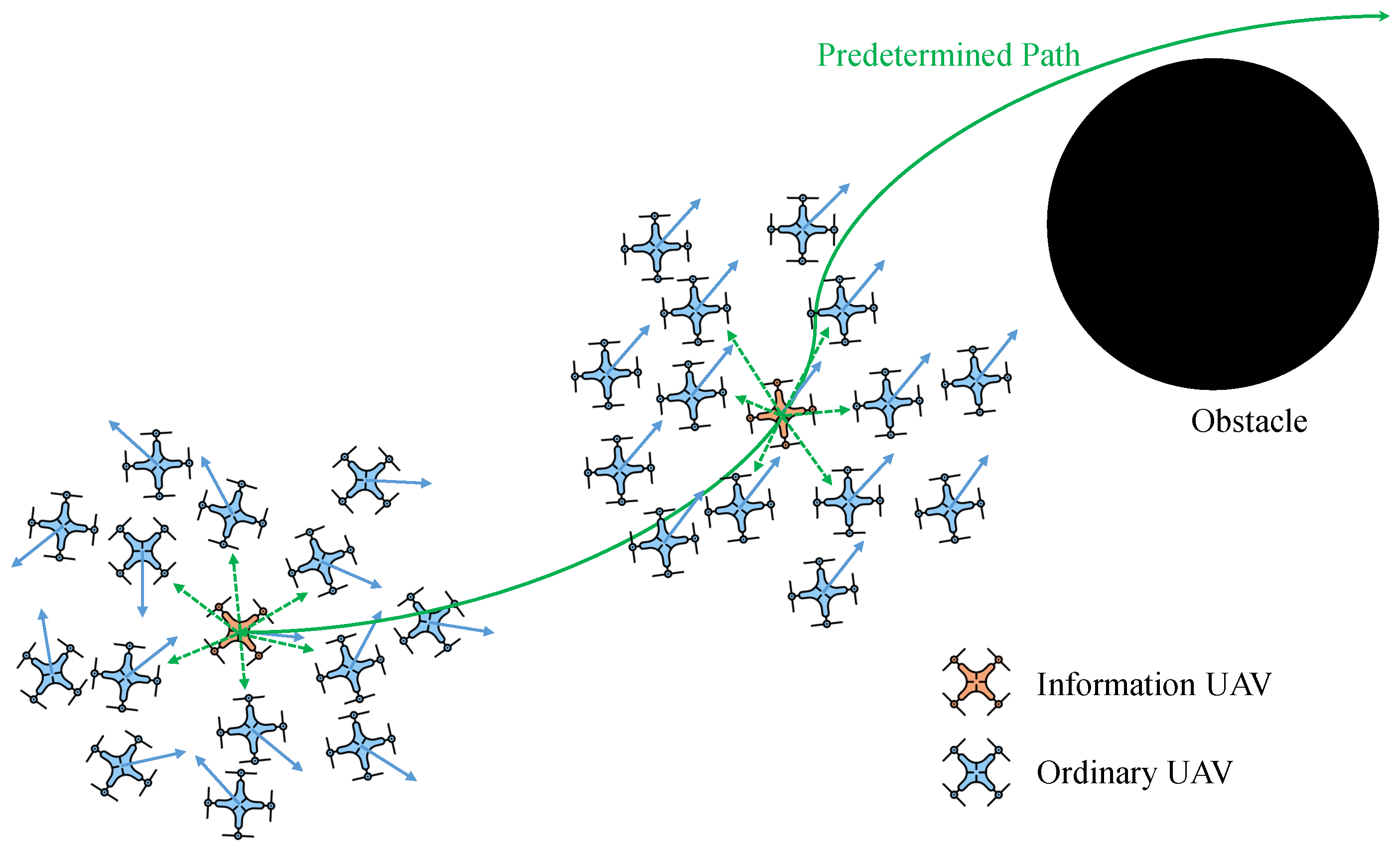
2. Flocking Navigation and Obstacle Avoidance with HWVEM

This section first proposes the hierarchical weighting mechanism. Then, according to that, a HWVEM is proposed to facilitate the rest of UAVs in aligning with the information UAV. Subsequently, an obstacle avoidance mechanism is designed to keep the UAV away from the obstacle. Finally, a HWVEM-based flocking algorithm is proposed to achieve both the flocking navigation and obstacle avoidance for a multi-UAV system.

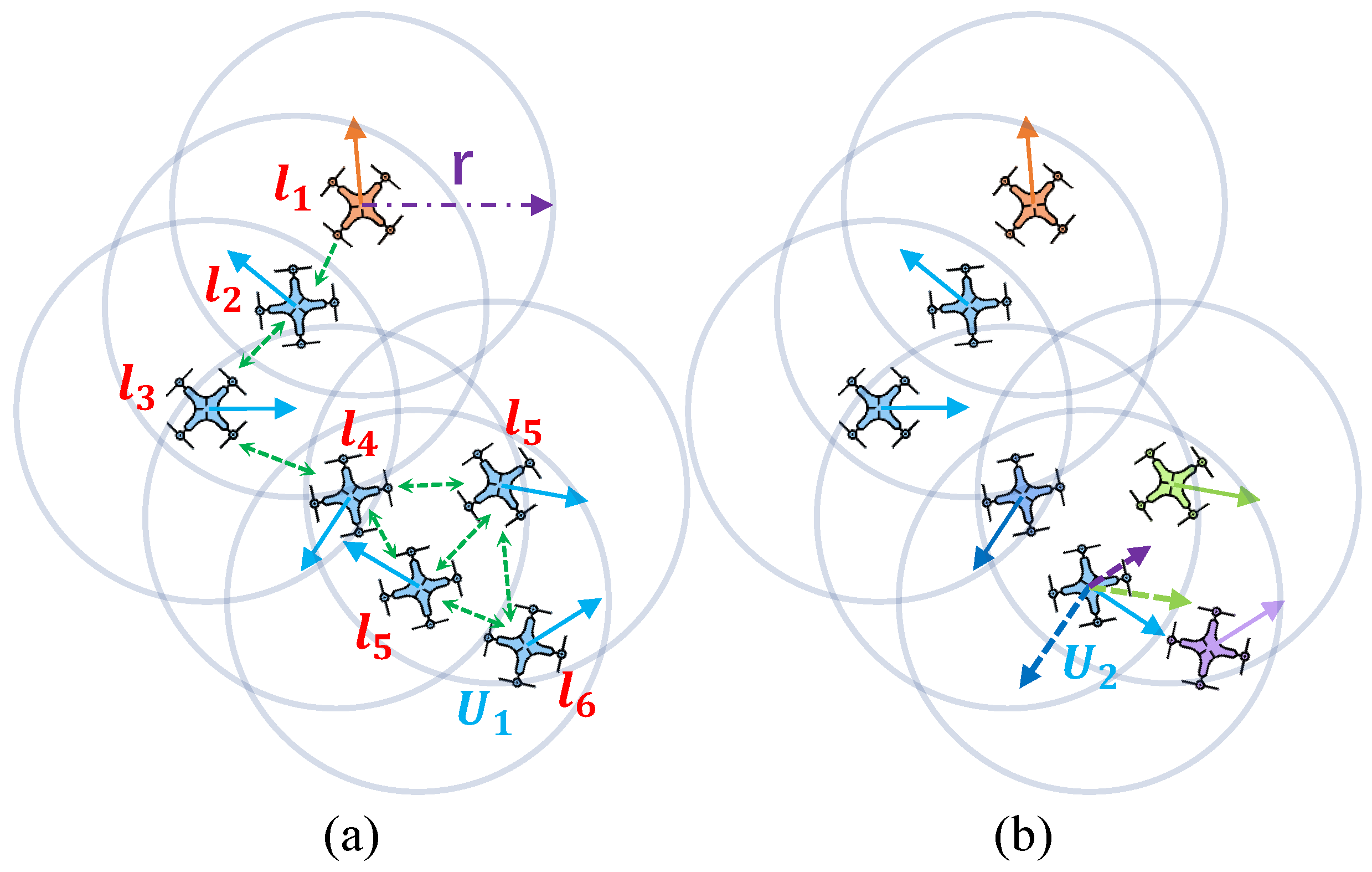
2.1. Hierarchical Weighting Mechanism

In our work, the multi-UAV system assumes that only the information UAV masters the predetermined path. To describe that capability, this paper applies the enable matrix E N = e i N × 1 , in which the element follows the rule,
e i ( k ) = 0 , if i Γ I U 1 , if i Γ I U ,
where i Γ I U means that the individual i is the information UAV [16].
Based on the topology with the information UAV, the rest of UAVs are divided into different layers (As shown in Figure 2a). The information UAV belongs to the 1-st layer and i Λ n means that the individual i belongs to the n-th layer. There is i Λ n if there exists the shortest sequence of neighborhoods
N q 1 , N q 2 , , N q n 1 ,
such that
q 2 N q 1 , q 3 N q 2 , , i N q n 1 ,
where n 1 denotes the length of the sequence and q 1 Γ I U . j N i means the individual j is the neighbourhood of the individual i and satisfies 0 < x i x j r , where x i represents the position of the individual i and r represents the interaction radius. The layer matrix L N = l i N × 1 is proposed to denote the layer of every UAV and the element l i follows the rule,
l i = 1 , if i Λ 1 2 , if i Λ 2 n , if i Λ n .
Transmitting the layer information between UAVs brings a time consumption, thereby the layer of the individual i at time step k is calculated based on the layers of its neighborhoods at time step k 1 . The layer of the UAV is one layer lower than the highest layer within its neighborhoods, which is updated by
l i ( k ) = min l j ( k 1 ) + 1 j N i ( k 1 ) .
Accordingly, a hierarchical topology network is established (Figure 2a). The upper-layer UAVs are more directly and quickly influenced by the information UAV. They are assigned with higher weight to ensure enough influence from the crucial information and to improve the speed of alignment of the individuals with the information UAV.

2.2. Hierarchical Weighting Vicsek Model

The information UAV adjusts its movement direction according to the mastered path information, as its heading angle θ d becomes the reference state for the rest of UAVs. In the Vicsek model [12], N individuals move at a constant speed v 0 on the D × D plane with periodic boundary in discrete time, and the UAV density is denoted as ρ = N / D 2 . At the initial moment, the position of the individual evenly distributes on the plane and the heading angle obeys [ 0 , 2 π ) uniform distribution. The heading angle of each individual at time step k + 1 is the average of the direction of its neighbours at time step k, which is updated by
θ i ( k + 1 ) = tan 1 j N i ( k ) sin θ j ( k ) j N i ( k ) cos θ j ( k ) + Δ θ i ( k ) ,
where N i ( k ) denotes the index set of the neighbourhoods of the individual i, and Δ θ i ( k ) [ η / 2 , η / 2 ] represents the noise, η is the noise intensity. The individual j is the neighbor of the individual i if requiring 0 < x j ( k ) x i ( k ) r , r is the interaction radius.
The velocity of the individual i is updated by
v i ( k + 1 ) = v 0 cos θ i ( k + 1 ) e 1 + v 0 sin θ i ( k + 1 ) e 2 ,
where e 1 and e 2 are mutually perpendicular unit vectors. The position of the individual i is updated by
x i ( k + 1 ) = x i ( k ) + v i ( k + 1 ) .
Considering that the system driven by VEM alone cannot achieve flocking navigation, and inspired by the hierarchical weighting mechanism, HWVEM is raised. In HWVEM, each individual has the same kinematic models as VEM, i.e., Equations (7) and (8). The heading angle of the individual is updated as follows,
θ i ( k + 1 ) = tan 1 j = 1 N h i j ( k ) sin θ j ( k ) j = 1 N h i j ( k ) cos θ j ( k ) + e i ( k ) · θ d ( k + 1 ) + Δ θ i ( k ) ,
where H N = h i j N × N is the neighbor matrix that describes the neighbor relationships of UAVs, in which the element is defined by
h i j ( k ) = a i j ( k ) · b i j ( k ) · c i j ( k ) , i , j = 1 , , N .
In the following, we will introduce the involved parameters i.e., a i j , b i j , c i j in more details.

2.2.1. Adjacency Matrix

The adjacency matrix A N = a i j N × N is used to describe the individuals within the interaction range of the given individual. Only the individuals within the interaction range can influence the given individual. The element a i j is expressed as
a i j ( k ) = 1 , if j N i ( k ) 0 , if j N i ( k ) .

2.2.2. Dominance Matrix

In the swarm, the heading angle of the information UAV will not be influenced by any other individual. For the UAVs of other layers, all individuals can be influenced by others. The flows of information among UAVs are shown in the Figure 2a. Only when the information of an individual flows to the given UAV, can it contribute to the given UAV [17]. The dominance matrix B N = b i j N × N is defined to describe the information flow direction between each pair of UAVs. When the information of the individual j flows to the i, b i j = 1 otherwise b i j = 0 . For HWVEM, the element b i j follows the rule,
b i j ( k ) = 0 , if i Λ 1 1 , if i Λ 1 .
The UAV does not contribute to its own new preferred movement direction, b i i ( k ) = 0 .

2.2.3. Contribution Matrix

The contribution matrix C N = c i j N × N is defined to describe the contribution intensity of every UAV during the decision-making process regarding the new preferred directions of the given UAV. The contribution intensity c i j of the individual j to the individual i consists of three parts: the absolute layer weight w j a b s of the individual j, the relative layer weight w j r e l of j, and the weight w i j n e i of the neighborhood layer status d i j of the individual i. Thus, the contribution c i j can be expressed as follows:
c i j ( k ) = w j a b s ( k ) · w j r e l ( k ) · w i j n e i ( k ) .

The Absolute Layer Weight

Individuals of the same layer are assigned with the same absolute weight. The higher the layer of the UAV, the earlier it will be affected by the information UAV, and the closer its direction is to the reference state. The absolute layer weight is used to characterize this attribute. The closer the individual direction is to the reference state, the higher the absolute weight it is assigned, and following this principle the faster the UAVs align themselves to the reference state. to encourage all UAVs to align to the reference state faster. Moreover, the absolute layer weight value cannot appear negative. Based on the above two properties, a simple yet effective form of the absolute weight can be designed as follows,
w i a b s ( k ) = 1 l i ( k ) + p 1 ,
where p 1 0 is the tuning parameter that is used to adjust the value of the absolute layer weight.

The Relative Layer Weight

The relative weight refers to the intensity that the given UAV contributes to the UAVs on its above, same, and beneath layer. As for the given UAV, considering its neighbors, among them the upper-layer individuals are the closest to the reference state, while the lower-layer is the opposite, and the individual from the same layer is the middle one. According to the relative topological distance between the individuals and the information UAV, the given individual possesses a higher weight to its lower layer individual and a lower weight to its upper layer. To simplify the model, in general, let the contribution intensity of the given individual to its same layer individual, and its upper layer and its lower layer be 1, 1 / p 2 and p 2 , respectively, where p 2 1 . The relative layer weight of every UAV is the same. w i r e l can be expressed as follows,
w i r e l ( k ) = 1 p 2 l i ( k ) .

The Weight of the Neighbourhood Layer Status

The neighbourhood layer status d i j is proposed to represent the status of the number of individuals at the layer of the individual j in the neighbours of the individual i, which is calculated by
d i j ( k ) = N i ( k ) n l n ( k ) = l j ( k ) , n N i ( k ) ,
where | · | represents the number of the elements of the set. When the individuals at the layer of the individual j is too few, j is assigned with higher weight to ensure that its layer can possess a certain contribution intensity. However, the influence of the neighbourhood layer status should not grow large nor become the dominant factor, so the natural logarithm is used to describe it. In this paper, when d i j > e , it means that there are too few individuals at the layer of the j. If the number of individuals at the layer of the j is enough, its contribution intensity is 1. Therefore, w i j n e i is designed as follows,
w i j n e i ( k ) = ln d i j ( k ) , if d i j ( k ) > e 1 , if d i j ( k ) e .

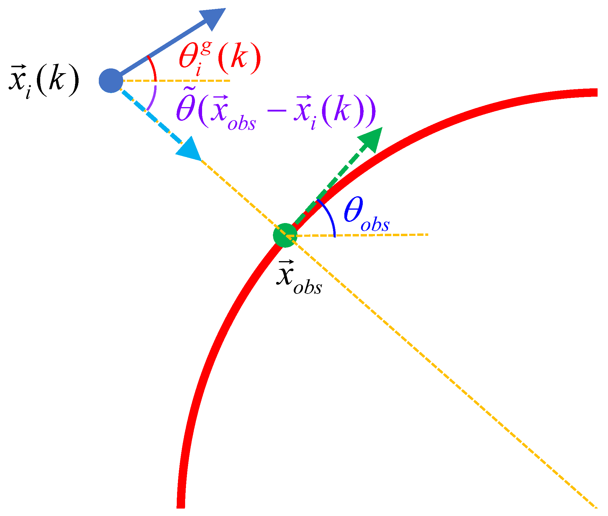
2.3. Obstacle Avoidance Mechanism

The insight behind our obstacle avoidance mechanism is to make the UAV who detects the obstacle move along the tangent direction of the obstacle [6]. Once the UAV detects an obstacle, it will first determine whether to take action to avoid the obstacle or not. Specifically, when the obstacle is in the way of UAV’s original movement direction, the UAV will align its heading angle to the tangent direction of that obstacle.
The genuine desired movement direction θ i g of the individual i represents the direction contributions of its neighborhoods, except the individuals who are avoiding the obstacle. The action of avoiding obstacles is both temporary and reactive, and is not a perpetual demand of the swarm. Ignoring the influence of the individual who is avoiding the obstacle, θ i g is updated by
θ i g ( k + 1 ) = θ d ( k + 1 ) , if i Λ 1 tan 1 j = 1 N h i j ( k ) o j ( k ) sin θ j ( k ) j = 1 N h i j ( k ) o j ( k ) cos θ j ( k ) , if i Λ 1 ,
where the element of the state matrix O N = o i N × 1 ,
o i ( k + 1 ) = 0 , if i Γ avoidance 1 , if i Γ avoidance ,
i Γ avoidance means that the individual i is taking action to avoid the obstacle.
The occasion to avoid the obstacle refers to when the position of the individual i, the genuine desired movement direction of i and the position of the nearest obstacle point satisfy the following constraints,
x i ( k ) x o b s r avoid ,
a b s θ i g ( k ) θ ˜ x o b s x i ( k ) θ obstruct ,
where x o b s represents the position of the nearest obstacle point, a b s ( · ) means the absolute value of the number, θ ˜ ( · ) denotes the angle between the vector and the x-axis of the inertial coordinate system, r avoid and θ obstruct represent the distance and the direction, respectively, that the obstacle can threaten the movement of the individual. If the vector is obtained by rotating x-axis counterclockwise, its heading angle takes a positive value, otherwise it is taken as a negative value. In this paper, r avoid = 0.5 , θ obstruct = 11 π / 20 .
If the individual i satisfies the constraints above, it will take action to avoid the obstacle. The strategy is to adjust its heading angle to align to the tangent direction of the nearest obstacle point and be consistent with the original direction as much as possible. The tangent direction can denote two opposite angles, the individual chooses the angle that makes an acute angle with the previous heading angle (i.e., θ obs in Figure 3). The UAV will not take action based on the obstacle point where there is no tangent. If it only detects the obstacle point without tangent, it will move in the original direction. The heading angle of the individual i is updated by
θ i ( k + 1 ) = θ i g ( k + 1 ) , if i Γ avoidance θ obs , if i Γ avoidance .

2.4. HWVEM-Based Flocking Algorithm

To achieve flocking navigation, it is still necessary to add attraction term and repulsion term for the multi-UAV system [18,19]. The attraction force is used to maintain the swarm compactness and the repulsion force is to avoid the collision. The form of attraction term is as follows:
v i a t t ( k + 1 ) = j N i 1 ( k ) r r e p x i j ( k ) r a t t r r e p · x i j ( k ) x i j ( k ) ,
where r a t t represents the range of the attraction force, r r e p represents the range of the repulsion force and j N i 1 satisfies r r e p < x i j r a t t . The form of repulsion term is as follows:
v i r e p ( k + 1 ) = j N i 2 ( k ) r r e p x i j ( k ) r r e p · x i j ( k ) x i j ( k ) ,
where j N i 2 satisfies 0 < x i j r r e p . The intensities of both terms of the UAVs of all layers to other individuals are the same and the information UAV is still not influenced by any other individual. The velocity of the UAV is updated according to the following equations:
v i des ( k + 1 ) = c a l i g n · v i a l i g n ( k + 1 ) + c r e p · v i r e p ( k + 1 ) + c a t t · v i a t t ( k + 1 ) ,
v i ( k + 1 ) = v i des ( k + 1 ) v i des ( k + 1 ) · min v i des ( k + 1 ) , v max ,
where c a l i g n , c r e p , c a t t represent the coefficients of the alignment term, the repulsion term and the attraction term, respectively, and v max represents the max velocity magnitude of the UAV, v max = 0.1 .
Accordingly, the HWVEM-based flocking algorithm is summarized as shown in Algorithm 1.
Algorithm 1 HWVEM-based flocking algorithm
Require:
       The position of each neighborhood individual j, x j ( k )
       The velocity of each neighborhood individual j, v j ( k )
       The layer of each neighborhood individual j, l j ( k 1 )
       The state of each neighborhood individual j, o j ( k 1 )
Ensure:
       The position of the individual i, x i ( k + 1 )
       The velocity of the individual i, v i ( k + 1 )
       The layer of the individual i, l i ( k )
1:
Calculate the adjacency matrix a i j ( k ) with (11)
2:
Calculate the dominance matrix b i j ( k ) with (12)
3:
Calculate the contribution matrix c i j ( k ) with (13)
4:
Calculate the coefficient matrix h i j ( k ) with (10)
5:
Update genuine direction θ i g ( k + 1 ) with (18)
6:
Update obstacle detection state o i ( k ) with (19)
7:
Update heading angle θ i ( k + 1 ) with (22)
8:
Update the alignment term v i align ( k + 1 ) with (7)
9:
Update the attraction term v i att ( k + 1 ) with (23)
10:
Update the repulsion term v i rep ( k + 1 ) with (24)
11:
Update the velocity v i ( k + 1 ) with (26)
12:
Update the position x i ( k + 1 ) with (8)
13:
Update the layer matrix l i ( k ) with (4)
14:
Return v i ( k + 1 ) , x i ( k + 1 ) , l i ( k )

3. Numerical Simulation and Analysis

This section first conducts numerical simulation experiments to test the alignment performance and verify the effectiveness of the designed hierarchical weighting mechanism. Then, the proposed HWVEM-based algorithm is applied to a complex mission scenario to demonstrate the flocking navigation and obstacle avoidance.

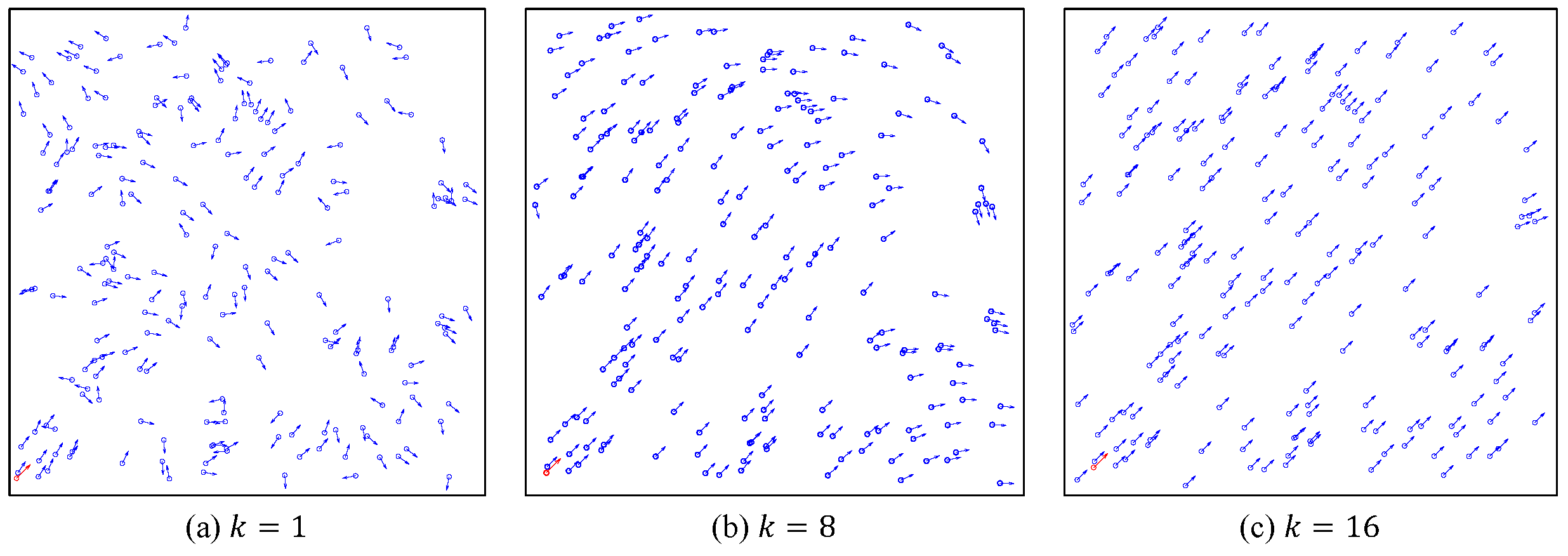
3.1. The Verification of the Model Alignment Performance

This section verifies whether all UAVs can converge to a fixed direction, which is the foundation of achieving flocking navigation. The attraction term and repulsion term are ignored and the simulation is carried out in a periodic boundary environment. We use the convergence time k con as performance metric:
k con = min k 0 k k 0 , Deg con ( k ) Deg con d ,
k con denotes the minimum time steps required for the system to reach the desired consistency degree Deg con d . Deg con represents the consistency degree between all UAVs’ heading angles and the reference state θ d ,
Deg con = π θ con k N / π ,
where
θ c o n ( k ) = θ 1 ( k ) θ d , θ 2 ( k ) θ d , , θ N ( k ) θ d .
The smaller the k c o n is, the shorter the time it is for all UAVs to converge to the reference state, the better the system performance is achieved.

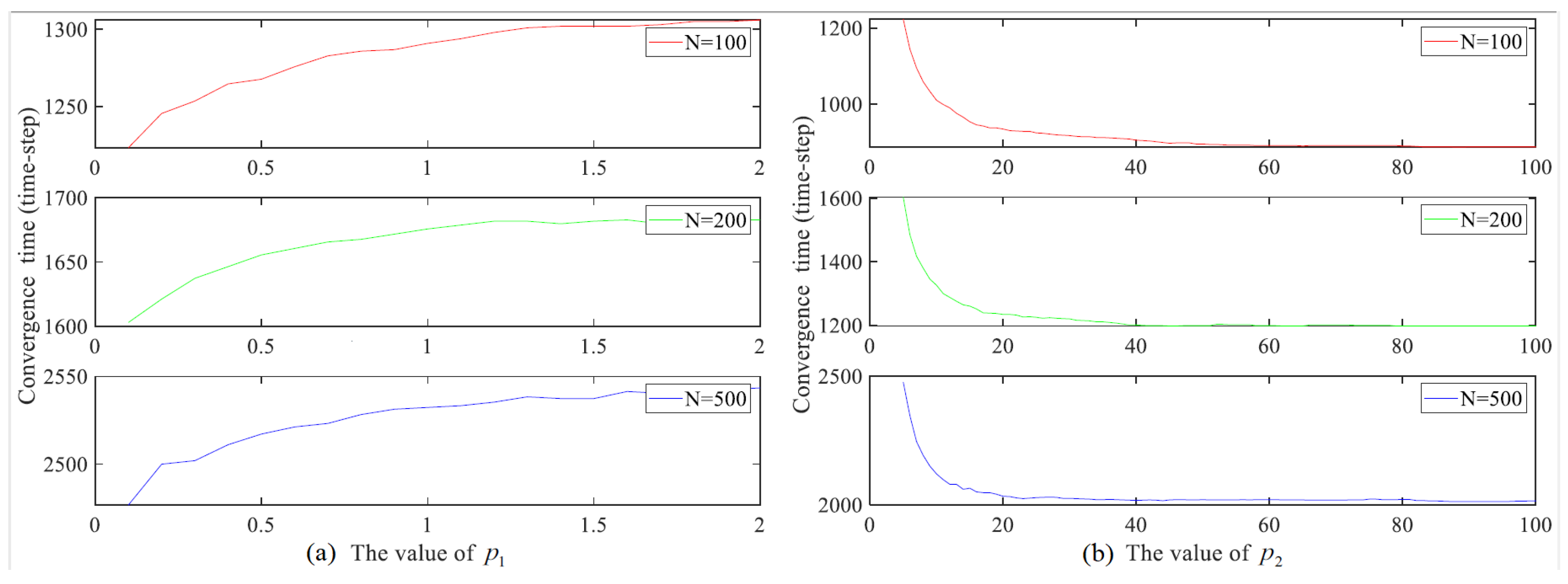
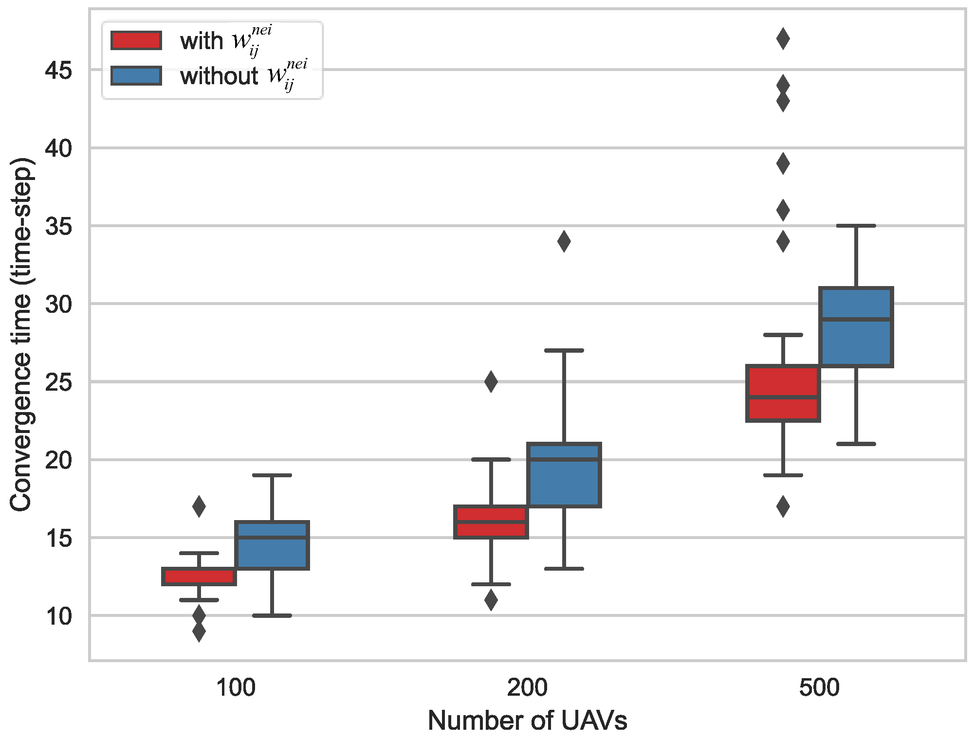
3.1.1. Contribution of Each Weighting Term

We first evaluate the model performance with different layer weighting parameters. The reference state is set to π / 4 . An exclusive information UAV is set with a π / 4 heading angle fixed, its initial position is at the lower left corner of the area. To stress that the feasibility of the alignment to the reference state is the focus of our studies, the noise will not be taken into account here. The following settings are the same: v 0 = 0.03 , ρ = 4.102 , r = 1 , Deg con d = 0.9984 , η = 0 . Three sets of groups are discussed: ( a ) N = 100 , D = 4.962 ; ( b ) N = 200 , D = 7 ; ( c ) N = 500 , D = 11.051 . The initial position and velocity of UAV also influence the convergence performance, and thereby the 100 simulations with different initial states are carried out for each parameter to avoid the randomness and obtain the general results.
Figure 4 shows the process of the multi-UAV system evolution. All of the individuals have transformed from the initial chaos and disorder to the final alignment, strongly testifying the reliability of the proposed model.
Figure 5 shows the average convergence time of the system with different layer weighting parameter. Intuitively, the convergence time increases with the increase of p 1 while decreasing with the increase of p 2 . The relative weight of the upper layer UAV and the given UAV decreases, following the increase of p 1 while increasing with the growing of p 2 . The upper layer UAV is closer to the reference state and is assigned with higher relative weight, which can induce the given UAV to align with the upper layer UAV faster, and thus the given UAV can converge to the reference state faster. Furthermore, as shown in Figure 5b, when the value of p 2 is quite large, especially p 2 50 , the convergence time is no longer significantly reduced. The reason is that the system performance has reached saturation. On one hand, as long as the given individual is affected by the upper layer individual, it can take the fastest action to align with the upper individual. On the other hand, even if the influence of the upper-layer continues to be improved, the given individual cannot take faster action to align to the reference state. Therefore, when p 2 is large enough, the system performance will not be further promoted with the increase of p 2 .
Then, the ablation experiment is carried out to verify the contribution of the mechanism of weighting the neighborhood layer status. The ablation results are shown in Figure 6.
As shown in Figure 6, the larger the group, the longer the convergence time. Obviously, weighting the neighborhood layer status brings better system performance. When the upper layer is lack of individuals, by this mechanism the contribution intensities can be improved to a certain extent compared to not applying the mechanism. The individuals can be induced to align with the upper layer individual and the reference state more quickly. When there are too few individuals of other layers, the contribution intensities provided by the mechanism are limited. The individuals of the upper layer are sufficient to induce the given individual to align with the reference state with the shortest time. This result demonstrates that the proposed mechanism of weighting the neighborhood layer status can improve the system performance.

3.1.2. Comparisons of Different Models

To further evaluate the performance of HWVEM, we compare it with five baseline models, i.e., the classic Vicsek model (VEM), the classic Vicsek model with one information UAV (VEM-A), the improved Vicsek model (IVEM) [15], the improved Vicsek model with one information UAV (IVEM-A), the weighting Vicsek model (WVEM) [16]. In IVEM, the individual obeys the rule of moving toward the middle of two neighbors’ motion directions with the maximum deviation. The updated model of the individual heading angle is as follows,
θ i ( k + 1 ) = θ i ( k ) + λ max p , q N i θ p ( k ) θ q ( k ) 2 ,
λ = 1 , if θ i min j N i θ j 0 , if min j N i θ j < θ i < max j N i θ j 1 , if θ i max j N i θ j .
Furthermore, to make IVEM adapt to the mission scenario and make sure all the individuals converge to the desired direction, a simple improved model named IVEM-A is proposed. In IVEM-A, the information UAV is introduced. If an individual can interact with the information UAV, it will take action based on the information of its neighbors, where the influence weight of the information UAV is 100 and ordinary UAV is 1. According to our previous work, the parameters k α = 30 , k β = 18 , k γ = 1 are purposely set for WVEM and the system can reach saturation (excellent) performance. k β means the weight of the UAVs who directly interact with the information UAV and k γ means the UAVs who not. For HWVEM, we simply set p 1 = 0.1 , p 2 = 5 . In these experiments, the reference state is set to π / 4 . The following settings are the same: v 0 = 0.03 , ρ = 4.102 , r = 1 , Deg con d = 0.9984 , η = 0 . Three sets of groups are discussed: ( a ) N = 100 , D = 4.962 ; ( b ) N = 200 , D = 7 ; ( c ) N = 500 , D = 11.051 . The simulations with different initial states are carried out 100 times for each model.
Table 1 shows the alignment performance of these models. Obviously, the convergence time of IVEM is shorter than VEM and the method of IVEM can enhance the convergence efficiency. As can be seen, both VEM-A and IVEM-A can induce the system to converge to the reference state π / 4 while the system inspired by VEM or IVEM cannot. The only difference between VEM-A and VEM, and also between IVEM and IVEM-A, is the information UAV, which indicates that the information UAV is the foundation for the system to converge to the reference state. In VEM-A or IVEM-A, the individuals are constantly directly or indirectly affected by the information UAV, leading to the tendency that they align with the information UAV and eventually align to the reference state. However, the convergence time increases greatly.
Compared with VEM-A and IVEM-A, the convergence time of WVEM is significantly shorter. WVEM proposes a fairly simple weighting mechanism. When considering the contribution intensity of an individual to the new preferred movement direction of the given individual, the highest weight is assigned to the information UAV, the second is assigned to the individuals directly interacting with the information UAV, and the least is assigned to other UAVs. By assigning the higher weight to the individual who is closer to the reference state, the whole system is induced to converge in a faster way to the reference state. Therefore, the system performance of WVEM is more superior, which demonstrates that an appropriate weighting mechanism can shorten the convergence time.
The time required by HWVEM is drastically shorter than WVEM. That is because HWVEM occupies the following improvements. Firstly, the exploration of the identity information of the UAV in HWVEM is more comprehensive and precise. The influence of the different individuals can be distinguished in a more detailed way and the weight of each individual can be set more flexibly. Secondly, the designed contribution intensity in HWVEM is no longer constant but dynamic. The designed rule is more reasonable and convincing. It can determine the intensity easily and flexibly and adapt to the large-scale multi-UAV system with lots of layers. Therefore, HWVEM performs better than WVEM and the weighting mechanism of HWVEM is more valid than WVEM.

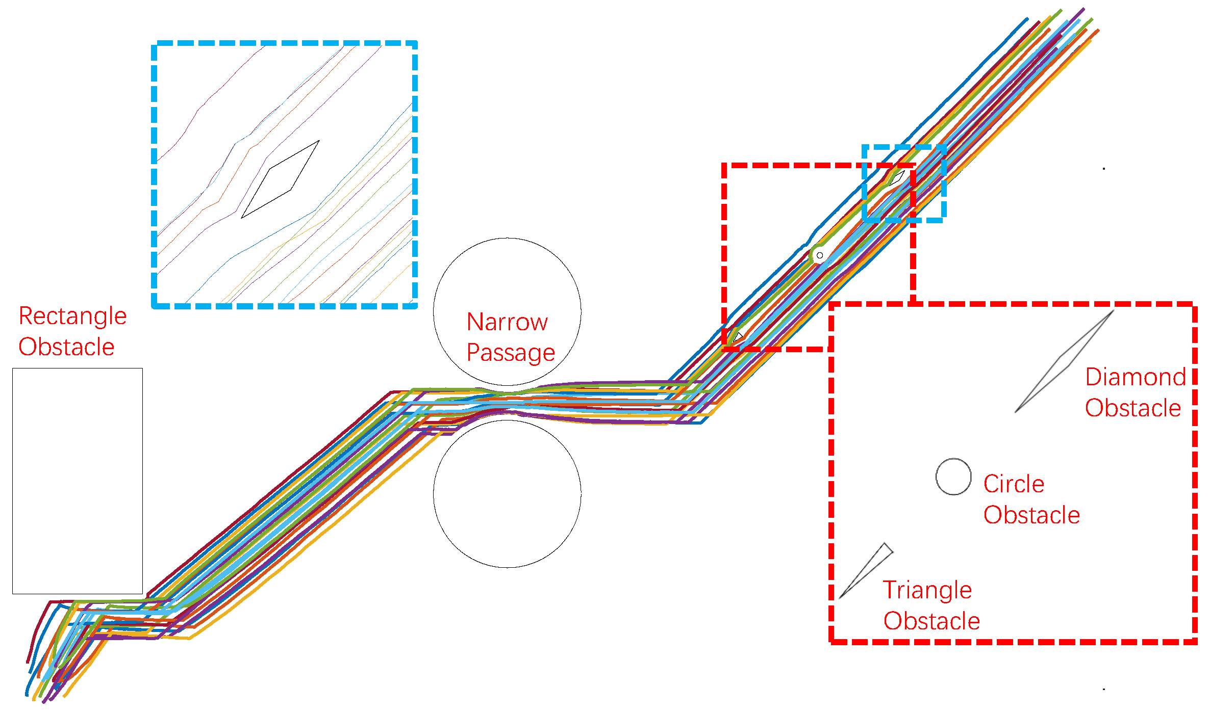
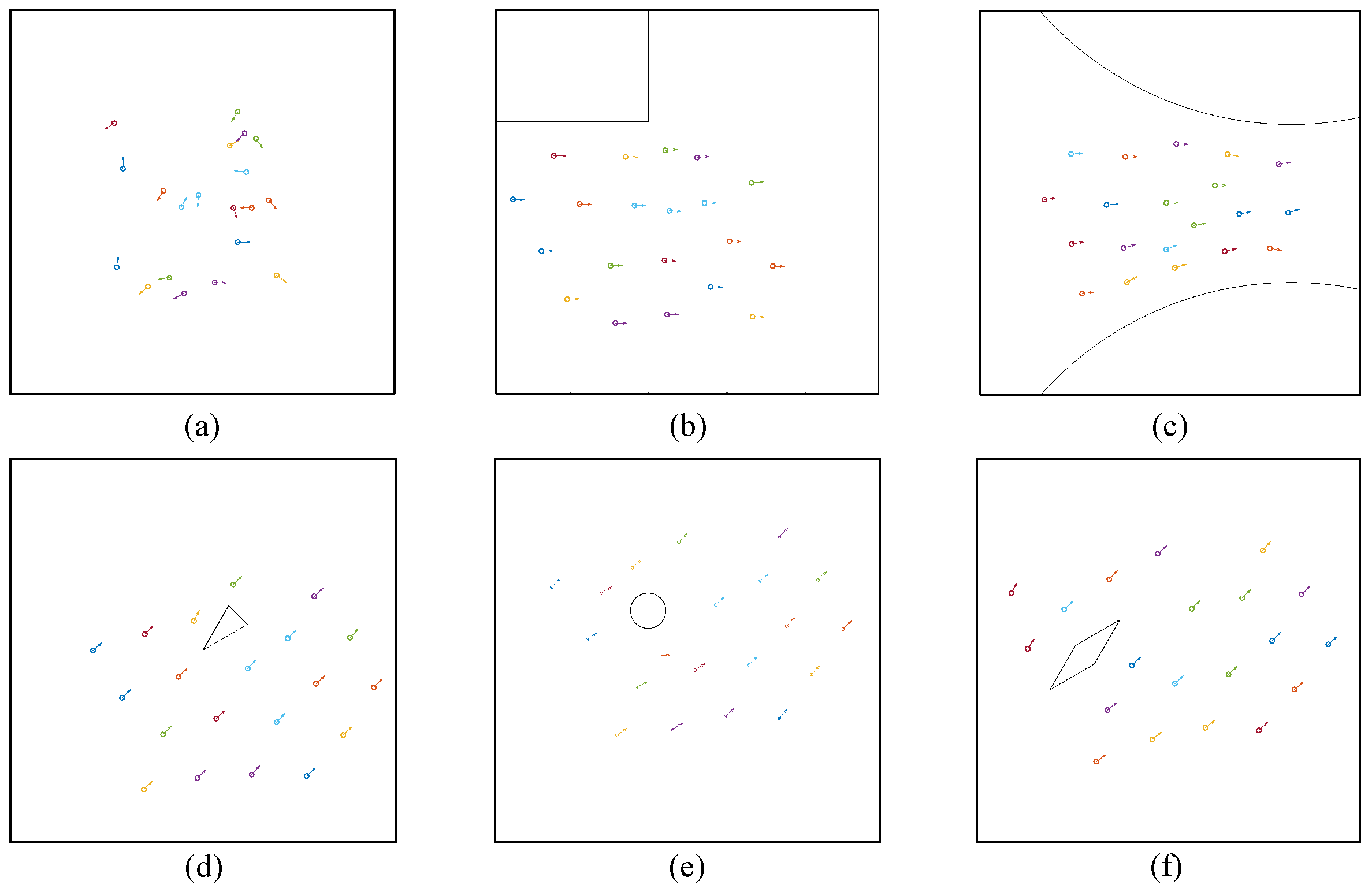
3.2. Flocking Performance in Complex Scenario

The UAVs driven by VEM and IVEM cannot converge to the reference state, so they cannot accomplish flocking navigation. Other models acquire different convergence time, and parts of UAVs cannot keep up with the information UAV in time in complex mission scenarios and thus lose track and fail to complete the task. This section will remove periodic boundary and add the attraction term and repulsion term to evaluate the task performance of the flocking algorithms based on VEM-A, IVEM-A, WVEM, and HWVEM, respectively. The influence of weighting parameters setting for HWVEM is also considered and two sets of parameters whose alignment performances vary greatly are chosen: p 1 = 0.1 , p 2 = 5 for HWVEM-I and p 1 = 0 , p 2 = 100 for HWVEM-II. In Figure 5 in Section 3.1.1, we can simply conclude that the alignment performance of HWVEM-II is much better than HWVEM-I.
We define the success rate P s as metric to evaluate the task performance. P s represents the proportion of the number of individuals that complete the task to the total individuals,
P s = N s N × 100 % ,
where N s represents the number of the UAVs that achieve the task successfully. The larger the P s and N s , the better the task performance. If a UAV follows the information UAV closely from the beginning to the end, it is considered to be successful. Besides, to evaluate the safety, two metrics are proposed: the minimum distance between individuals D ind and the minimum distance from the individual to the obstacle D obs during the entire process. The larger the D ind and D obs , the safer the swarm.
In the experiments, a certain degree of noise is introduced to test the system robustness. The following settings are the same: v 0 = 0.1 , ρ = 3.265 , r = 1 , c align = 1 , r align = 1 , c rep = 0.1 , r rep = 0.7 , c att = 0.003 , r att = 1 , η = 0.1 . To reduce computational burden and take the actual group into account, three sets of groups are discussed: ( a ) N = 5 , D = 1.2375 ; ( b ) N = 20 , D = 2.4749 ; ( c ) N = 50 , D = 3.9132 . One-hundred simulations with different initial states are carried out for each model.
Figure 7 shows the entire mission scenario and task execution of HWVEM and Figure 8 displays the snapshots. As shown in Figure 7, the mission scenario is comprehensive, including traveling through narrow areas, and bypassing tiny or huge obstacles. The shapes of the obstacles include spheres, rectangles, diamonds, and triangles. In this experiment, all UAVs align with the information UAV within a short time and follow closely with the information UAV during the entire process, which illustrates that the swarm moves along the predetermined path successfully. Besides, the safety is demonstrated because no collision happened during the whole process. These results verified the feasibility and adaptability of HWVEM. The system can still complete the mission in the presence of noise, which shows that the model is robust and can be used to guide the actual flocking.
As shown in Table 2, when N = 5 , all five models possess a relatively high success rate. Since the group is not large, every model can induce the UAVs to align with the information UAV within a short enough time. Nevertheless, VEM-A and IVEM-A acquire the lowest success rate, which is consist with their alignment performances.
When N = 20 , the task performances of VEM-A and IVEM-A decline sharply. Once the system reaches a certain large group, the difference of task performance between the models begins to manifest. The task performance of HWVEM is the best, which is consistent with the alignment performance. It implies the rationality of our idea.
When N = 50 , the performance of HWVEM-II is significantly higher than HWVEM-I. The better the parameters for the system convergence performance, the better the performance of the multi-UAV system executing the mission, which emphasizes the importance of the weighting parameter configurations.
Additionally, the values of D ind and D obs of different models are always similar, which shows the same system safety. The values are always positive and the minimal values are D ind = 0.0427 , D obs = 0.0492 . It shows that a certain degree of security of the multi-UAV system can be guaranteed.

4. Conclusions

This paper proposed a HWVEM based on VEM to achieve the flocking navigation and obstacle avoidance for the multi-UAV system in which only one UAV knows the predetermined path. According to the hierarchical weighting mechanism, all UAVs are divided into different layers based on their topological distance with the information UAV. The contribution intensity of each individual is assigned reasonably and flexibly, which is composed of three parts: the absolute layer weight, the relative layer weight, and the weight of the neighborhood layer status. The rationality of each part has been verified through numerous experiments. The proposed obstacle avoidance mechanism consists of two steps: occasion and behavior. Specifically, when the obstacle obstructs the genuine desired movement direction of the UAV, the UAV will align its heading angle to the tangent direction of the obstacle. The feasibility and reliability of HWVEM have been verified by comparing it with several baseline models in comprehensive mission scenario. Additionally, the system can still achieve mission in the presence of noise, which demonstrates the robustness of HWVEM and its potential in the real world. In the future, we will further evaluate our proposed model in the real-world environment. Another promising direction is to search the optimal weights for HWVEM via intelligent optimization algorithms, such as genetic algorithm (GA) and particle swarm optimization algorithm (PSO).

Author Contributions

Conceptualization, X.X.; Data curation, D.T.; Formal analysis, C.Y.; Funding acquisition, H.Z.; Investigation, X.L.; Methodology, C.Y.; Project administration, Y.C.; Resources, X.X.; Software, X.L.; Supervision, H.Z.; Validation, X.L.; Visualization, X.L. and C.Y.; Writing—original draft, X.L.; Writing—review & editing, C.Y., H.Z. and Y.C. All authors have read and agreed to the published version of the manuscript.

Funding

This research was supported by National Nature Science Foundation under grant 61803377 and Postgraduate Scientific Research Innovation Project of Hunan Province under grant CX20210001.

Institutional Review Board Statement

Not applicable.

Informed Consent Statement

Not applicable.

Data Availability Statement

The data used to support the findings of this study are available from the corresponding author upon request.

Conflicts of Interest

The authors declare they have no conflict of interest.

References

  1. Kim, A.R.; Keshmiri, S.; Blevins, A.; Shukla, D.; Huang, W. Control of Multi-Agent Collaborative Fixed-Wing UASs in Unstructured Environment. J. Intell. Robot. Syst. 2019, 97, 205–225. [Google Scholar] [CrossRef]
  2. Parrish, J.; Edelstein-Keshet, L. Complexity, pattern, and evolutionary trade-offs in animal aggregation. Science 1999, 284, 99–101. [Google Scholar] [CrossRef] [PubMed]
  3. Couzin, I. Collective minds. Nature 2007, 445, 715. [Google Scholar] [CrossRef] [PubMed]
  4. Vicsek, T.; Zafeiris, A. Collective motion. Phys. Rep. 2012, 517, 71–140. [Google Scholar] [CrossRef] [Green Version]
  5. Beaver, L.E.; Malikopoulos, A.A. An Overview on Optimal Flocking. arXiv 2020, arXiv:2009.14279. [Google Scholar]
  6. Olcay, E.; Schuhmann, F.; Lohmann, B. Collective navigation of a multi-robot system in an unknown environment. Robot. Auton. Syst. 2020, 132, 103604. [Google Scholar] [CrossRef]
  7. Yan, C.; Xiang, X.; Wang, C. Fixed-Wing UAVs flocking in continuous spaces: A Deep reinforcement learning approach. Robot. Auton. Syst. 2020, 131, 103594. [Google Scholar] [CrossRef]
  8. Chen, H.; Cong, Y.; Wang, X.; Xu, X.; Shen, L. Coordinated Path-Following Control of Fixed-Wing Unmanned Aerial Vehicles. IEEE Trans. Syst. Man Cybern. Syst. 2021, 99, 1–15. [Google Scholar]
  9. Hoang, D.; Tran, D.M.; Tran, T.S.; Pham, H.A. An adaptive weighting mechanism for reynolds rules-based flocking control scheme. Peerj Comput. Sci. 2021, 7, 1–15. [Google Scholar] [CrossRef] [PubMed]
  10. Hayes, A.T.; Dormiani-Tabatabaei, P. Self-organized flocking with agent failure: Off-line optimization and demonstration with real robots. In Proceedings of the IEEE International Conference on Robotics & Automation, Washington, DC, USA, 11–15 May 2002; IEEE: Piscataway, NJ, USA, 2002. [Google Scholar]
  11. Zhou, H.; Zhao, H.; Han, T.; Huang, H.Q. Cooperative flight and evasion control of uav swarm based on rules. Syst. Eng. Electron. 2016, 38, 1374–1382. [Google Scholar]
  12. Vicsek, T.; Czirók, A.; Ben-Jacob, E.; Cohen, I.; Shochet, O. Novel type of phase transition in a system of self-driven drones. Phys. Rev. Lett. 1995, 75, 1226–1229. [Google Scholar] [CrossRef] [Green Version]
  13. Zhang, J.; Zhao, Y.; Tian, B.; Peng, L.; Zhang, H.T.; Wang, B.H.; Zhou, T. Accelerating consensus of self-driven swarm via adaptive speed. Phys. Stat. Mech. Its Appl. 2009, 388, 1237–1242. [Google Scholar] [CrossRef] [Green Version]
  14. Gao, J.; Chen, Z.; Cai, Y.; Xu, X. Approach to enhance convergence efficiency of Vicsek model. Control. Decis. 2009, 24, 1269–1272. [Google Scholar]
  15. Chen, S.; Shu, J.; Nie, S.; Cen, Y. Convergence Efficiency of a Class of Improved Vicsek Model. Inf. Control. 2011, 40, 318–322. [Google Scholar]
  16. Liu, X.; Xiang, X.; Chang, Y.; Yan, C.; Zhou, H.; Tang, D. Hierarchical Weighting Vicsek Model for Flocking Navigation of Drones. Drones 2021, 5, 74. [Google Scholar] [CrossRef]
  17. Jia, Y.; Vicsek, T. Modelling Hierarchical Flocking. New J. Phys. 2019, 21, 093048. [Google Scholar] [CrossRef]
  18. Vásárhelyi, G.; Virágh, C.; Somorjai, G.; Tarcai, N.; Szörényi, T.; Nepusz, T.; Vicsek, T. Outdoor flocking and formation flight with autonomous aerial robots. In Proceedings of the 2014 IEEE/RSJ International Conference on Intelligent Robots and Systems, Chicago, IL, USA, 14–18 September 2014; pp. 3866–3873. [Google Scholar]
  19. Reynolds, C.W. Flocks, Herds, and Schools: A Distributed Behavioral Model. ACM SIGGRAPH Comput. Graph. 1987, 21, 25–34. [Google Scholar] [CrossRef] [Green Version]
Figure 1. The scenario of flocking navigation with obstacle avoidance. The Information UAV (the red UAV) adjusts its heading angle according to the predetermined path information it learns in advance. The objective of this paper is to make sure that all the blue UAVs follow the red one closely and avoid the obstacle successfully.
Aerospace 08 00286 g001
Figure 2. Relationships between UAVs. (a) Definition of different layers of UAVs and interaction topology diagram between UAVs. (b) Vector synthesis of UAV velocity. The individual U 1 belongs to the 6-th layer instead of the 7-th layer because the length of the shortest neighborhood sequence is 5. In (a), the direction of the green dashed arrow represents the movement information flow direction. (b) shows the synthesis process of the movement direction of the individual U 2 . The dotted line represents the influence of other individuals on U 2 and the length represents the contribution intensity.
Aerospace 08 00286 g002
Figure 3. The expression of related variables in the process of the UAV avoiding the obstacle. The red curve represents the obstacle, and the green point represents the nearest obstacle point to the individual.
Aerospace 08 00286 g003
Figure 4. The process of one evolution with N = 200 , L = 7 , p 1 = 0.1 , p 2 = 5 . The red individual represents the information UAV.
Aerospace 08 00286 g004
Figure 5. The performance of different group with different layer weighting parameter. (a) Different values of p 1 with p 2 = 5 . (b) Different values of p 2 with p 1 = 0.01 .
Aerospace 08 00286 g005
Figure 6. The box-plot for system performance under different application circumstances of the neighborhood layer status. The red boxes represent the system performance with the mechanism of weighting the neighborhood layer and the blue boxes without. The black rhombus are the extreme outliers.
Aerospace 08 00286 g006
Figure 7. The scene of the system executing the mission. The inset of red dotted line represents the setup of the obstacles. The blue dotted line shows the detail that the individual avoids the obstacle.
Aerospace 08 00286 g007
Figure 8. The snapshots of the multi-UAV system executing the mission. (a) k = 1 ; (b) k = 80 ; (c) k = 320 ; (d) k = 485 ; (e) k = 560 ; (f) k = 630 .
Aerospace 08 00286 g008
Table 1. The alignment performance of VEM, VEM-A, IVEM, IVEM-A, WVEM and HWVEM.
Test Case SetupMethodConvergence
Time (Time-Step)
Converge to
Reference State
Number of
UAVs
SizeAvg25th pctl50th pctl75th pctl
1004.96 × 4.96VEM84.3155.0081.00105.50No
VEM-A568.39362.50542.50741.00Yes
IVEM62.0247.0062.0074.50No
IVEM-A556.05527.00559.00584.00Yes
WVEM113.7083.5097.00122.00Yes
HWVEM12.2312.0012.0013.00Yes
2007 × 7VEM153.74104.00135.50193.50No
VEM-A1236.60701.50969.001489.50Yes
IVEM78.0348.5070.0096.00No
IVEM-A1170.621012.501180.501290.50Yes
WVEM238.57152.50185.50301.50Yes
HWVEM16.0315.0016.0017.00Yes
50011.2 × 11.2VEM296.30204.50282.50357.00No
VEM-A4097.301550.503157.004333.00Yes
IVEM40.6534.5039.0045.50No
IVEM-A4662.113462.503807.004730.00Yes
WVEM662.36370.50656.00757.00Yes
HWVEM24.7722.5024.5026.00Yes
Table 2. The task performance of VEM-A, IVEM-A, WVEM, HWVEM-I and HWVEM-II.
Test Case SetupMethod P s (%) D obs D ind
Number of
UAVs
Initial
Size
Avg25th
pctl
50th
pctl
75th
pctl
AvgAvg
51.24
×
1.24
VEM-A69.5860.0080.0080.000.17790.1873
IVEM-A69.6060.0060.0080.000.18210.1799
WVEM76.4060.0080.00100.000.17560.1738
HWVEM-I86.4080.0080.00100.000.18480.1702
HWVEM-II86.0080.0080.00100.000.18090.1623
202.47
×
2.47
VEM-A31.6110.0020.0045.000.08320.1576
IVEM-A44.6530.0040.0055.000.08520.1168
WVEM71.0560.0065.0080.000.08280.0962
HWVEM-I83.8065.00100.00100.000.08360.0887
HWVEM-II83.8565.0097.50100.000.08320.0823
503.91
×
3.91
VEM-A9.294.006.0012.000.05280.155
IVEM-A17.6612.0016.0021.000.05260.1105
WVEM52.5442.0052.0062.000.05350.0772
HWVEM-I82.6254.00100.00100.000.04920.0485
HWVEM-II88.3897.00100.00100.000.05010.0427
Publisher’s Note: MDPI stays neutral with regard to jurisdictional claims in published maps and institutional affiliations.

