Article

Finite Element Method-Based Optimisation of Magnetic Coupler Design for Safe Operation of Hybrid UAVs

1
Department of Electrical and Electronics Engineering, Gazi University, Graduate School of Natural and Applied Sciences, 06500 Ankara, Turkey
2
Department of Electrical Electronics Engineering, Çankaya University, 06790 Ankara, Turkey
3
Department of Electrical and Electronics Engineering, Gazi University, 06560 Ankara, Turkey
*
Author to whom correspondence should be addressed.
Aerospace 2023, 10(2), 140; https://doi.org/10.3390/aerospace10020140
Submission received: 12 December 2022 / Revised: 27 January 2023 / Accepted: 30 January 2023 / Published: 2 February 2023

Abstract

:
The integration of compact concepts and advances in permanent-magnet technology improve the safety, usability, endurance, and simplicity of unmanned aerial vehicles (UAVs) while also providing long-term operation without maintenance and larger air gap use. These developments have revealed the demand for the use of magnetic couplers to magnetically isolate aircraft engines and starter-generator shafts, allowing contactless torque transmission. This paper explores the design aspects of an active cylindrical-type magnetic coupler based on finite element analyses to achieve an optimum model for hybrid UAVs using a piston engine. The novel model is parameterised in Ansys Maxwell for optimetric solutions, including magnetostatics and transients. The criteria of material selection, coupler types, and topologies are discussed. The Torque-Speed bench is set up for dynamic and static tests. The highest torque density is obtained in the 10-pole configuration with an embrace of 0.98. In addition, the loss of synchronisation caused by the piston engine shaft locking and misalignment in the case of bearing problems is also examined. The magnetic coupler efficiency is above 94% at the maximum speed. The error margin of the numerical simulations is 8% for the Maxwell 2D and 4.5% for 3D. Correction coefficients of 1.2 for the Maxwell 2D and 1.1 for 3D are proposed.

1. Introduction

Newly increased environmental apprehension, consciousness, and continuous development to improve the safety and reliability of all aircraft are some of the biggest challenges to be addressed in aviation. Such impressive and challenging issues require the development of more efficient and innovative hybrid systems, as shown in Figure 1.
In conventional systems, the propulsion system of small UAVs is provided only by fuel engines, usually piston engines (PEs). In hybrid systems, there is a high-speed, direct-drive, and highly efficient electric machine called starter/generator (S/G) [1] that provides the initial starting mechanism of the PE and charges the system battery group in generator mode while cruising or contributes to the propulsion in motor mode during climbing.
The modernisation of unmanned aerial vehicles (UAVs) under the concept of More Electric Aircraft (MEA) has been on the agenda. However, the challenge of isolating the shafts of the aircraft engine and the electrically driven system, typically the S/G, for more functional and stealthy operations [2] imposes a critical function on magnetic couplers (MCs). MCs provide both contactless torque transmission and hermetic separation using static seals or containment shrouds, which are essential for hybrid UAVs.
MCs have significant advantages such as overload protection, reduced maintenance, simple design, and highly tolerant shaft misalignment, vibration, and noise absorption. An MC consists of permanent magnets (PMs), rotor yokes, a protective cover to protect PMs from high speeds, a containment shroud for sealing, and shafts. Typically, it consists of two rotating parts, an inner and outer rotor, and is grouped as shown in Figure 2 [3].
Active and reactive couplers have PMs inserted into both rotors. In reactive couplers, the PMs are mounted on only one-half of the rotor, while the other half is steel in the form of PMs. The inner and outer rotors rotate at synchronous speed. The hysteresis and eddy-current couplers have PMs on the half-rotor side, while the other side has hysteresis and conductive materials, respectively. The inner and outer rotor speeds are not the same.
Recently, substantial work has been concentrated on MCs using analytical and numerical approaches. Carpentier et al. [4] suggested implementing the analytical virtual work approach to the framework of the volume integral method to compute the magnetic forces. Li et al. [5] obtained 3D analytical torque equations with a closed form for an ideal radial MC. Ravaud et al. [6] performed a 3D semi-analytical study of the transmitted torque between uniformly magnetised PMs based on the Coulombian model. The theoretical aspects of these studies are predominant. Apart from this, the coupler parameters affecting the transferable torque have not been comparatively studied.
On the other hand, studies have accelerated with the development of powerful numerical analysers [7] using finite element methods (FEMs) [8]. Ziolkowski et al. [9] compared transient, quasi-static, and fast-quasi-static modelling techniques to calculate force profiles using FEMs. Ose-Zala et al. [10] investigated the influence of basic design parameters on the mechanical torque for cylindrical MCs with rounded PMs using QuickField software based on 2D FEMs. Kang et al. [11] showed the torque calculation and parametric analysis of synchronous PM couplers. The analytical results are compared with 2D FEMs. Nevertheless, different temperature and grade conditions of PMs have not been studied. Torque variations against different rotor materials have not yet been investigated.
Baiba Ose et al. [12] examined the influence of the PM width and the number of pole pairs on the mechanical torque of MCs. Meng et al. [13] performed transient magnetic field calculations for MCs by using Ansys Maxwell 3D software. However, the studies do not simultaneously examine multi-objective design parameters that affect each other.
In addition, different MC topologies [14] have been the subject of comparison. Kang et al. [15] compared the torque of synchronous PM couplers with parallel and Halbach-magnetised magnets by using field calculations. Recently, studies of an axially magnetised MC [16] have been reported. At the same time, magnetic gear concepts [17,18,19] inspired by mechanical gearboxes were studied. Structures combining magnetic gears and electrical machines [20,21] have begun to be developed. Moreover, hybrid coupler studies [22] have become widespread. Loss calculations [23,24] for MC efficiency studies are shown. However, static tests in response to torque angle variations have not been investigated.
MCs are safely used in many areas [25,26,27], such as automotive, marine, pump, and compressor applications. One of the practical benefits of MCs is to prevent mechanical faults [28,29] due to torque overloads in some critical applications with the help of slipping when excessive torque is applied. MCs are also impactful for use in hazardous or corrosive environments while transmitting torque through a containment shroud [30].
Optimisation studies [31,32] have been performed to achieve the optimum design. Furthermore, it has been investigated whether magnetic bearings [33] could be used instead of mechanical bearings to reduce maintenance and operating costs.
Although not in large numbers, MCs have started to be used in the aviation industry [34,35]. Benarous et al. [36] summarised all the findings and revealed test data from a magnetic gear coupler designed for an aerospace application. Finally, coreless design [37], which is demanded chiefly in aviation applications, has also been mentioned.
Since most systems traditionally have design limitations that directly affect output characteristics, the system-specific design of MCs is required where performance investigations against correlative system parameters are considered.
This paper clarifies the design aspects and implications of active cylindrical MCs, particularly for small-sized UAVs, to achieve the optimum design. The use of proposed MCs in hybrid UAVs comprising PE and S/G units is important because they provide a significant advantage in protecting the UAV, especially under severe conditions such as excessive loading and shaft lock-up [38,39]. In such catastrophic situations, the S/G is operated in motor mode, allowing the UAV to continue its cruise mission or land safely with the help of the loss of synchronisation between the inner and outer rotors of the MC, as shown in Figure 3. Although this loss of synchronisation may seem like a problem in ordinary machine designs, the use of MCs provides a great advantage in terms of protection against breakage in hybrid UAVs.
The novel MC is part of the customised Bearcat F85F model aircraft, which is a 60% hybrid by replacing the conventional 3W-140i PE [40] with the 3W-55XI PE and S/G of 6 kW and 4500 rpm. The MCs are prototyped, and the given dimensions are verified.
The main contribution of this paper is to explore the effects of the design parameters of the MC by applying a multi-objective optimisation approach. Supporting the numerical analyses with experiments and systematically collecting the results under a unique study paves the way for researchers to facilitate the design process and validate the proof of concept. This work is distinguished from other studies with the following novelties:
  • Performing transient analysis on the dynamically modelled state of the MC;
  • Dynamic investigation of the effect of misalignments on the transmitted torque;
  • Examination of the MC efficiency depending on the operating speed at a critical angle;
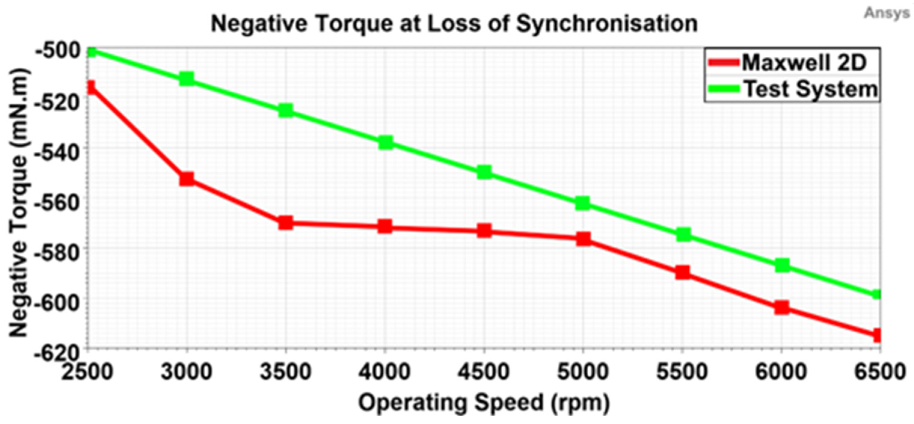
  • Exploring the negative torque between the rotors in case of a loss of synchronisation;
  • Proposing the correction coefficients to identify the error margin of simulations.
In addition, exploring the effect of PM temperature changes, orientations, and grades on pullout torque increases the novelty of the article. In previous studies, the multi-objective optimisation of the MC design was considered analytically [10,11,12,13,14]. However, nonlinear parameters affecting the performance, such as leakage flux, core losses, and end effects, are ignored in analytical methods to avoid complex and time-consuming calculations. In addition, the eddy-current losses induced in the PMs due to the continuously varying torque angle depending on the natural vibration of the piston engine are very difficult to handle analytically. Therefore, it requires more precise FEM analysis.
For this purpose, the design parameters are considered as a whole, and accordingly, the system is numerically optimised. Thus, the leakage flux, core losses, and end effects are evaluated with the FEM model. The efficiency of the optimised MC is considered an important performance indicator and is analysed together with the nonlinear effects of the materials. Furthermore, the experimental verification of an optimised FEM model in accordance with PE output parameters for hybrid UAVs also makes this study interesting for researchers. The experimental results are in agreement with the FEM outputs.
This study consists of four main frameworks. Section 2 covers design considerations such as dimension criteria, constraints, and rotor topologies. Analytical pre-dimensioning and FEMs by Ansys Maxwell are included in Section 3. The MC is dynamically modelled to improve the simulation accuracy. The effects of the air gap clearance, model length, pole numbers, PM thickness, and thickness of the rotor yokes are investigated in magnetostatics and transients. The torque ripple of the MC is explored. Section 4 comparatively presents and discusses the performance test results of the MCs with different design parameters carried out on the dynamic test bench. Locked-rotor and dynamic tests are performed with steps, full loads, and overloads [41]. Finally, the findings are reviewed in Section 5.

2. Design Considerations

The block diagrams of the hybrid UAV system and the proposed model are shown in Figure 3a,b, respectively. Numerous criteria are used for UAV classification [42], such as the mean take-off weight (MTOW), size, operating conditions, and capabilities.
The modernised Bearcat F85F Warbirds 1/4.2 scale aircraft with 22 kg, 256 cm wingspan, 204 cm length, and 150 m ceiling altitude is in the Open Category A3 (small size) based on European Union Aviation Safety Agency (EASA) regulations [43,44].
The maximum torque of the replaced 3W-55XI PE and, therefore, the minimum torque to be transmitted by the MC is 4.4 N·m. However, considering the load variations due to sudden manoeuvres, a safety factor of 1.2 is determined. In addition, the correction coefficient of 1.3 is initially chosen at the beginning of the design to account for the simulation errors and high starting kickback torque of the PE. Accordingly, in light of the MTOW, including PE and S/G, the allowable weight and length for the MC are set by the manufacturer at 375 g and 15 mm, respectively. The optimisation parameters of the MC design sought in the design reviews and given by the UAV manufacturer are summarised in Table 1.
In the design of active couplers, an objective function such as torque per magnet volume, torque per coupler volume, or cost per weight should be considered to obtain the final design. The minimum weight that meets the requirements is often preferred for hybrid UAVs. However, the optimum design study is based on the achievable maximum torque within the manufacturable size and weight limitations to compensate for the unpredictable high kickback torque experienced during the initial start-up of the PE. The optimal design parameters are identified in Section 3.5 by comparing different topologies. MCs are also classified by the shape of PMs [45], such as star-type, cylindrical, ring-type, rectangular or sector shape, and toothed surface. In terms of practical use, the cylindrical type is more popular. Further classification can be performed according to the magnetisation direction of PMs as radial, axial, and linear orientations. The active cylindrical type is intended for synchronous speed and radial motion requirements.

2.1. Determination of the Minimum Outer Diameter of the Inner Rotor

The inner rotor of the MC is directly connected to the flange of the PE, as marked in red in Figure 4a, thus providing magnetic separation [46] between the shafts of the PE and S/G to improve the safe operation [47] of the hybrid UAV.
The design of the MC should start from the inner rotor to the outer rotor, as opposed to the conventional method, due to the diameter limitations of the inner flange in the 3W-55XI PE, as shown in Figure 4b. It is ensured that the outer rotor of the MC is also the rotor of the S/G to take advantage of this design limitation.

2.2. Selection of Rotor Topology

Figure 5a–f illustrate the conventional rotor topologies selected depending on the objective function and the application area. Some disruptive topologies have also been applied, such as Halbach arrays to increase the field strength of PMs, as shown in Figure 5g [15], and enhanced hybrid couplers to increase the torque density, as shown in Figure 5h [48]. However, arc surface PMs are preferred due to the ease of fabrication and access.

2.3. Materials Overview

Electric steel, carbon steel, and metals are used as MC rotor materials. NdFeB and SmCo stand out among ferrite, ceramic, and alnico magnets due to their high energy density. Epoxy, the most common type of coating for aerospace applications, has been preferred among coating types such as zinc, gold, plastic, nickel, and Teflon. The temperature assignment of PMs is made at 80 degrees Celsius, which is the most likely to be encountered in the system. In some special cases, a protective sleeve made of stainless steel, fibres, or plastics is used to prevent the PMs from leaving the rotor surface.
The containment shroud for sealing fixed to the stationary part of the MC hermetically separates the inner and outer rotors. There are several materials, such as nonferrous stainless steel, Hastelloy, carbon fibre peek, oxide ceramics, and nonmetallics.

3. Design Studies

Analytical approaches [49,50] are simple and fast methods for estimating preliminary design dimensions. The margins of error are high because the calculations are made under the assumptions that the magnetisation of PMs is homogeneous, the model length and the average air gap radius are very large compared to the PM thickness and air gap length, and the rotor materials are not saturated and have high permeability [51]. However, analytical calculations involving these effects are laborious and complicated.

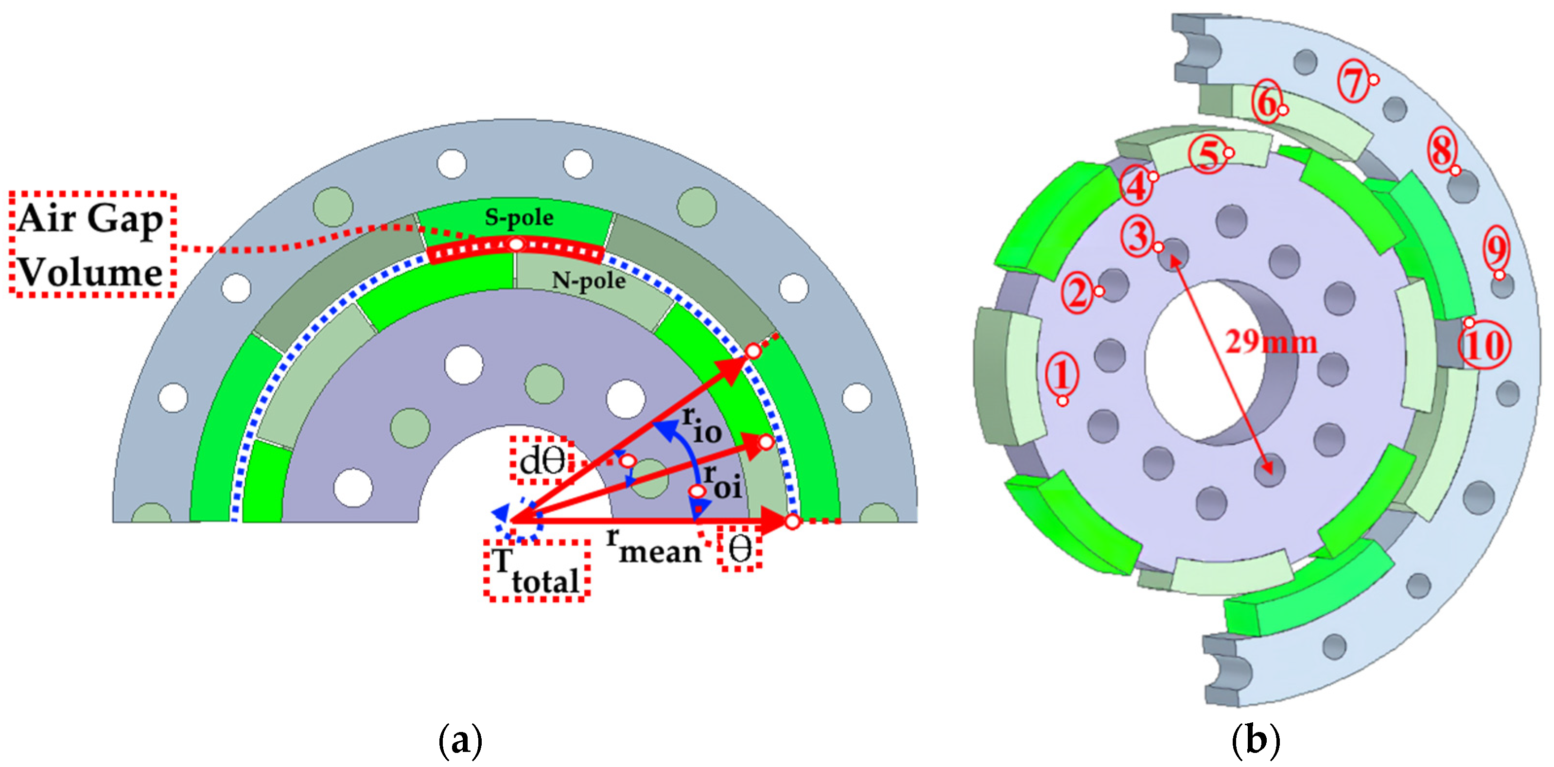
3.1. Analytical Preliminary Sizing

The analytical subdomain method based on the Maxwell stress tensor and virtual work approach are accurate methods for the analytical calculations of the transmitted torque of MCs. The analytical subdomain method uses Laplace’s and Poisson’s equations [7] for the air gap and PM regions to find the flux density distribution by using the derivative of the vector potential equation in the air gap, as in Equations (1) and (2). Then, the transmitted torque is calculated from the Maxwell stress tensor method as in Equation (3).
B I I r ( r , θ ) = 1 r A I I θ
B I I θ ( r , θ ) = 1 r A I I θ
T = l s r m e a n µ 0 0 2 π [ B I I r ( r m e a n , θ ) B I I θ ( r m e a n , θ ) ] d θ
where B I I r ( r , θ )   and   B I I θ ( r , θ ) are the air gap flux density distributions depending on the radial distance (r) and angle (θ) according to polar coordinate adoption, respectively. A I I   and   l s are the vector potential in the air gap and the total model active length, respectively. r m e a n is the radius of the middle of the air gap, as shown in Figure 6a. roi and rio are the outer radius of the inner rotor and inner diameter of the outer rotor, respectively.
However, the virtual work method [52] is a practical approach for the fast calculation of the air gap volume depending on the angular displacement between the PMs based on the energy change in the air gap and is given as follows.
T t o t a l = d W d θ = ( B g 1 ) 2 ( V a g ) 2 µ 0 ( θ d θ ) ( 2 p )
where d W ,   θ ,   d θ ,     B g 1 ,     V a g ,   2 p are the change in stored energy in the air gap in joules, mechanical angle of a pole in radians, angular displacement between poles depending on the load, fundamental component of the flux density in the middle of the air gap in Tesla, air gap volume in m3, and the number of poles, respectively. T t o t a l is the total torque exerted on the middle of the air gap used to estimate the torque on the rotors with regard to the total number of poles. The active couplers work without any slip until the pullout torque is exceeded. The pullout torque is expressed as the maximum torque that the MC can handle.
The model of the proposed cylindrical MC comprises an inner and outer rotor (1,7), weight reduction holes (2,9), mounting holes (3,8), PM housings (4,10), and PMs (5,6), as illustrated in Figure 6b.
The torque angle (θ) is the mechanical angle between the d-axes of the inner rotor PMs and the outer rotor PMs when the MC is loaded, as shown in Figure 6a. The angle at the maximum torque is called the critical angle [3] and is calculated as in Equation (5), equivalent to 90 electrical degrees.
Mdeg represents the mechanical angle. The critical angle is 18 Mdeg and 0.314 radians for 10-poles. Preliminary sizing calculations are performed using Equation (4) and summarised in Table 2 for the 10-pole configuration at the critical angle in which (θ-dθ) is directly equal to dθ. The θ is 36 Mdeg and 0.628 radians for 10-poles.
θ c r i t i c a l = 360 ° ( 2 p ) 2   ,     M d e g
The respective air gap volume is calculated as 1289.5 mm3. The bore diameter of the inner rotor is 29 mm due to the mounting hole diameters on the flange, as shown in Figure 4b. Similarly, the outer diameter of the inner rotor is to be a minimum of 43 mm for the model. Considering the thickness of the rotor yokes and PMs, rmean is initially chosen to be 27.5 mm. With the initial assumption of an air gap length of 1.5 mm, the outer diameter of the inner rotor and the inner diameter of the outer rotor are found to be 26.75 mm and 28.25 mm, respectively. Thus, the corresponding model length is found to be 5 mm.

3.2. Maxwell 2D Static Analyses

The increased ability to use all processor cores and the symmetry properties tend to directly use FEM-based software in the design and optimisation of MCs [53], resulting in a tangible increase in simulation accuracy. The FEM accurately calculates the air gap flux density and transmitted torque by considering the material nonlinearities, leakage fluxes, core losses, PM magnetisation directions and temperature changes, induced eddy-current losses on PMs, and dynamic effects on the MC.
Ansys Maxwell multi-functional analyses are performed in a magnetostatic environment for static simulations and in a transient environment for dynamic simulations [54].

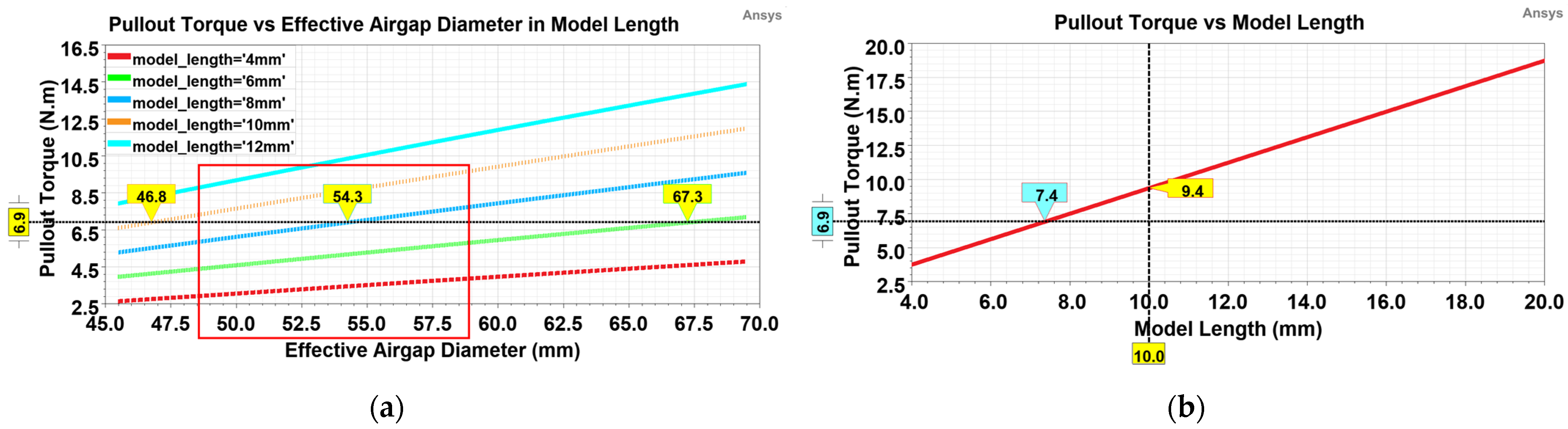
3.2.1. Correlation of Effective Air Gap Diameter and Model Length

The analyses are started with a 10-pole configuration to determine the effective air gap diameter and the model length for the required torque and torque density. Considering the air gap and yoke thicknesses, the analysis started with a minimum effective air gap diameter of 45 mm. The effective air gap is defined as the middle of the air gap.
Figure 7 investigates the pullout torque for the range of effective air gap diameters and model lengths. Figure 7a shows that the required pullout torque of 6.9 N·m specified in Table 1 is met with a minimum effective air gap diameter of 47 mm for a model length of 10 mm or a minimum model length of 6 mm for an effective air gap length of 67 mm.
The relationship between the effective air gap diameter and the length of the MC directly affects the inertia and transferrable torque of the hybrid UAV. The choice of an effective air gap diameter as high as possible will increase the system inertia and allow modular construction for higher torque transmissions. Therefore, the effective air gap diameter is chosen to be 57.5 mm, approaching the maximum limit of the range.
On the other hand, the linear increase in the model length corresponds to an almost linear increase in the pullout torque. The required torque of 6.9 N·m is achieved with a minimum coupler length of 7.4 mm, as shown in Figure 7b. However, for easy manufacturability and higher tolerance to disturbance, the length is chosen to be 10 mm, in which case the pullout torque is 9.4 N·m, hereafter referred to as the updated torque requirement.

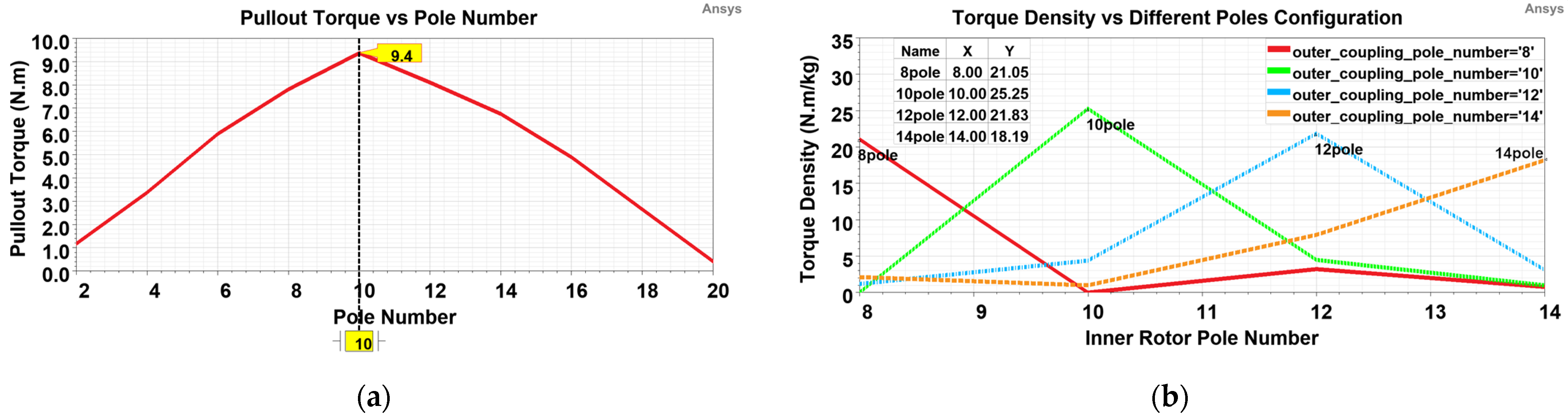
3.2.2. Investigation of Optimum Pole Number

In magnetic systems, such as MCs, the pole number configuration of the rotors significantly affects the transmitted torque and, thus, the torque density. The pole number of 10 for the inner and outer rotors is chosen as the optimum point because the highest pullout torque is provided, as shown in Figure 8a.
On the other hand, Figure 8b examines viable or impracticable cases of the torque density for different numbers of inner and outer rotor poles. The torque density expresses the pullout torque per unit weight in N·m/kg. The torque density decreases dramatically in the case of different inner and outer rotor pole number configurations. However, a different number of poles on both rotors is possible with the appropriate design of the modulator in the air gap. Thus, the magnetic gear concept [19] is formed.

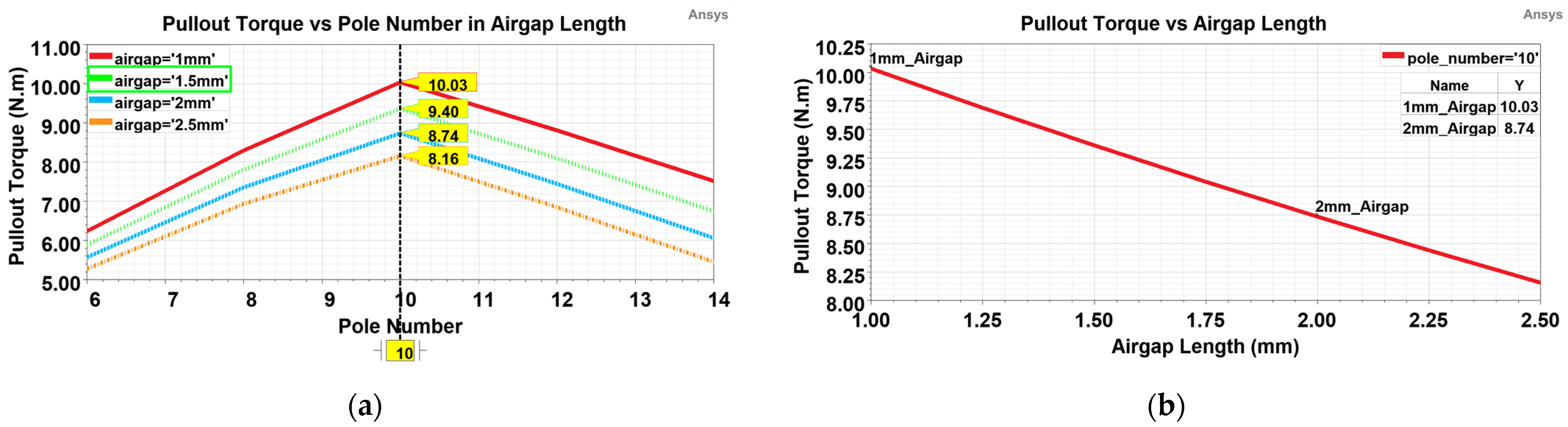
3.2.3. Effect of Air Gap Clearance on Pullout Torque

Air gap clearance has a direct effect on the torque since it affects the total reluctance. Reducing the air gap will increase the torque, as seen in Figure 9, but it will also increase production costs and cause the rotors to rub against each other in the case of imbalance.
Considering the fabrication issues and PE vibration, the air gap is set to 1.5 mm, as marked in green in Figure 9a. A twofold increase in the air gap length does not mean a twofold reduction in the torque but instead a reduction of 13%, as shown in Figure 9b.

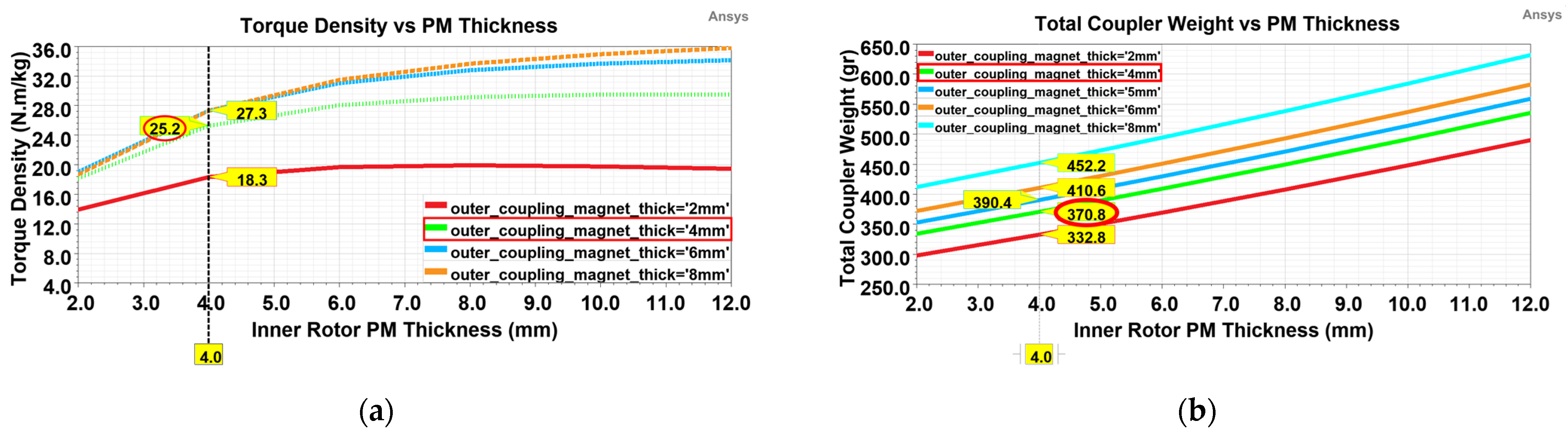
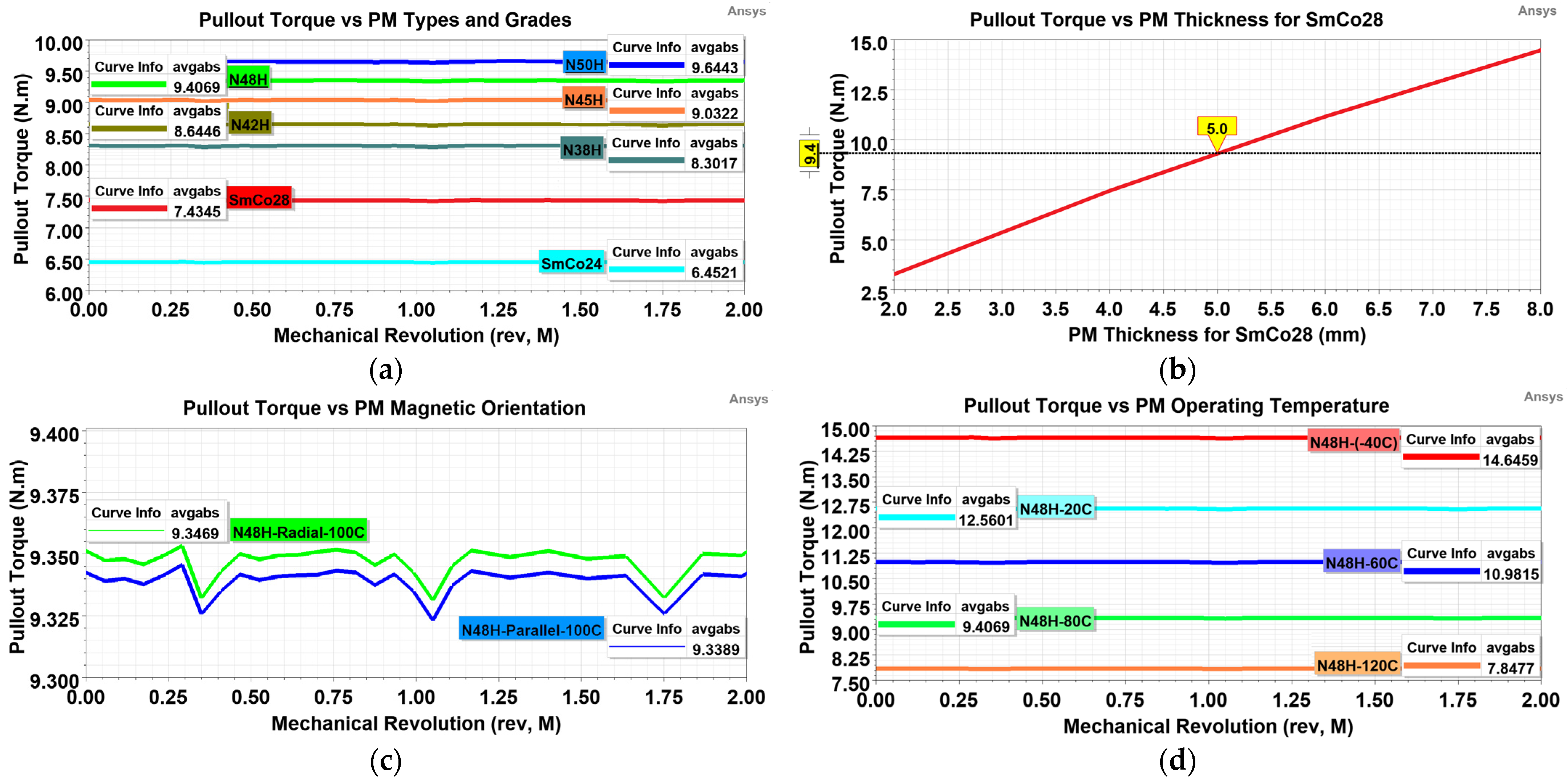
3.2.4. Determination of PM Thickness

The PM thickness changes the average flux density in the air gap and, hence, the transmitted torque [55]. The thickness of the inner rotor PMs is set at 4 mm because the maximum increase in the torque density is met, as shown in Figure 10a. On the other hand, the thickness of the outer rotor PMs of 4 mm is chosen because the maximum weight of 375 gr is reached, as illustrated in red in Figure 10b.

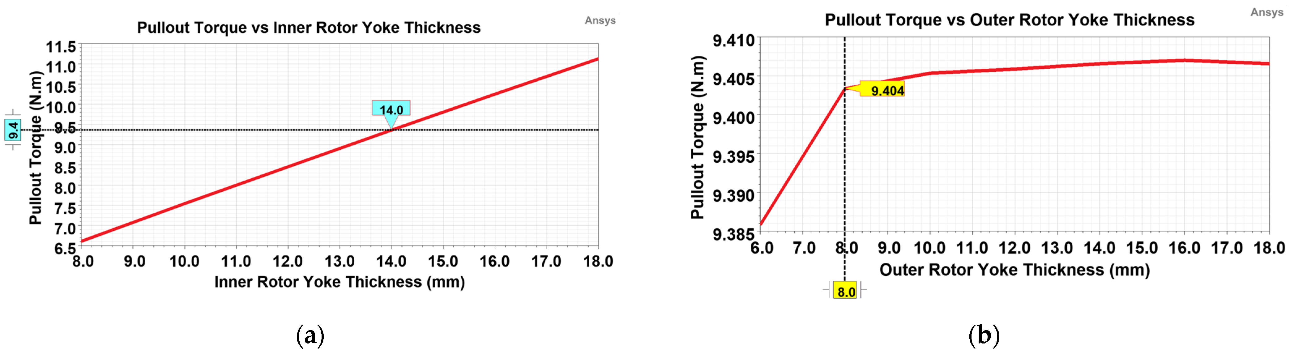
3.2.5. Determination of the Thickness of Rotor Yokes

The thickness of the rotor yokes should be selected carefully, as it changes the total reluctance and, hence, the air gap magnetic flux density. The minimum thickness of the rotor yokes that meet the updated torque requirement results in the minimum coupler weight.
For this purpose, the inner and outer rotor yoke thicknesses are determined to be 14 mm and 8 mm, as shown in Figure 11a and Figure 11b, respectively. The choice of the values is evaluated based on a fraction-free approach for ease of production and in light of the minimum wall thickness necessary to eliminate material deformation during fabrication.

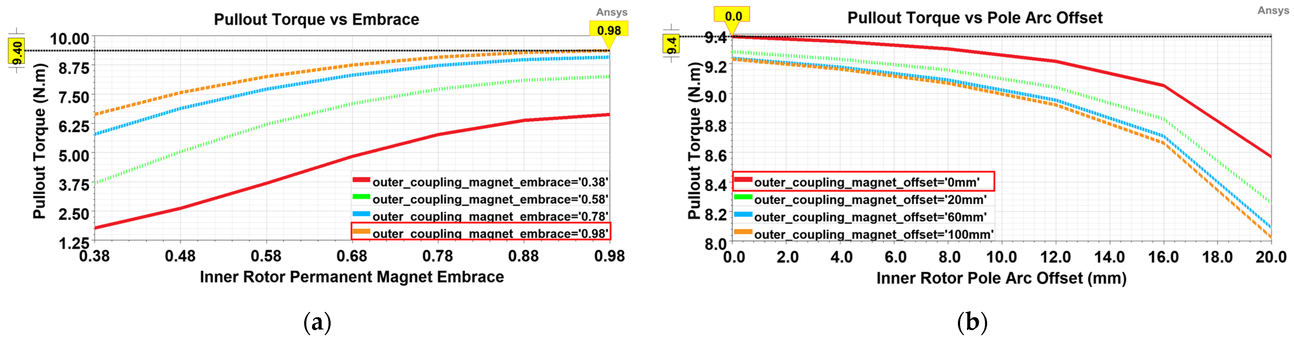
3.2.6. Investigation of the PM Embrace and Offset Effect

Pole embrace represents the ratio of the pole arc to the pole pitch. The arched PMs may not be concentric with the rotor. In the absence of a uniform air gap, the offset between the centre of the bottom and top of the PM arc is called the pole arc offset. The embrace has a more significant effect on the pullout torque, while the offset has a limited effect.
The embrace of 0.98 offers a higher torque density, as marked in red in Figure 12a. The pole arc offset may not be preferred because it negatively affects the output torque, as seen in Figure 12b, except for mandatory situations such as cogging torque. Thus, the maximum pullout torque is achieved with the maximum embrace and minimum offset.

3.3. Maxwell 2D Transient Analyses

Transient analyses allow performance outputs corresponding to the design parameters to be dynamically realised under no-load, rated-load, and overload conditions. Simulations are carried out in which the moment of inertia, the mechanical losses in terms of damping factors, and the load type acting are modelled. Thus, the moment of inertia of the inner and outer rotors is calculated as 0.42 kg-cm2 and 1.95 kg-cm2, respectively. Mechanical losses, i.e., wind and friction losses, ventilator losses, and bearing losses, are practically accepted at 3.5% of the output power [56]. The load type is considered such that the load varies nonlinearly with the square of the speed, such as fan load [54].

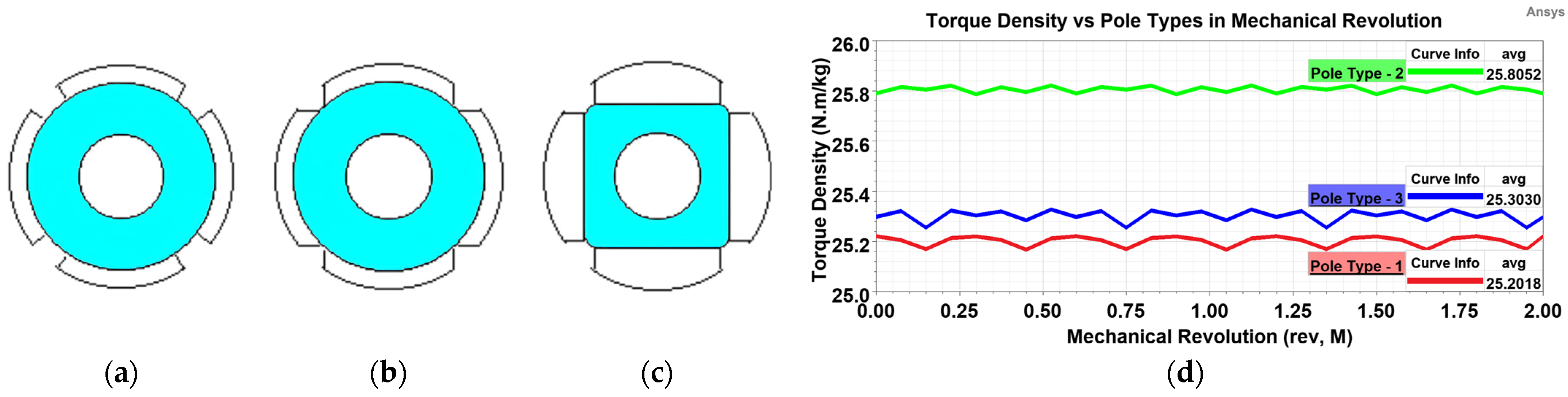
3.3.1. Comparison of Pole Types

The pole types applied to the PM machines can also be employed in the MCs. Surface-mounted PMs are more production viable than internal PMs and can be divided into three parts, as shown in Figure 13a–c. Figure 13d shows that the effect of the pole type on the torque density is minimal. However, type-1 is preferred due to its ease of installation.

3.3.2. Effect of PM Type, Grade, and Temperature on Pullout Torque

The grade, type, orientation, and operating temperature of PMs have a significant role in MC design. Figure 14 examines all implications for the 10-pole configuration at a critical angle. The pullout torque increases with the increasing PM grade, as shown in Figure 14a. On the other hand, SmCo magnets can operate at higher temperatures and in harsher conditions. Nevertheless, their energy density is lower than that of NdFeB, resulting in a lower pullout torque, as shown in Figure 14b for the same thickness of PMs.
In addition, the magnetisation direction has little effect on the pullout torque, as shown in Figure 14c. However, the operating temperature of the PMs significantly affects the torque, as shown in Figure 14d. Radially oriented N48H is preferred for accessibility.

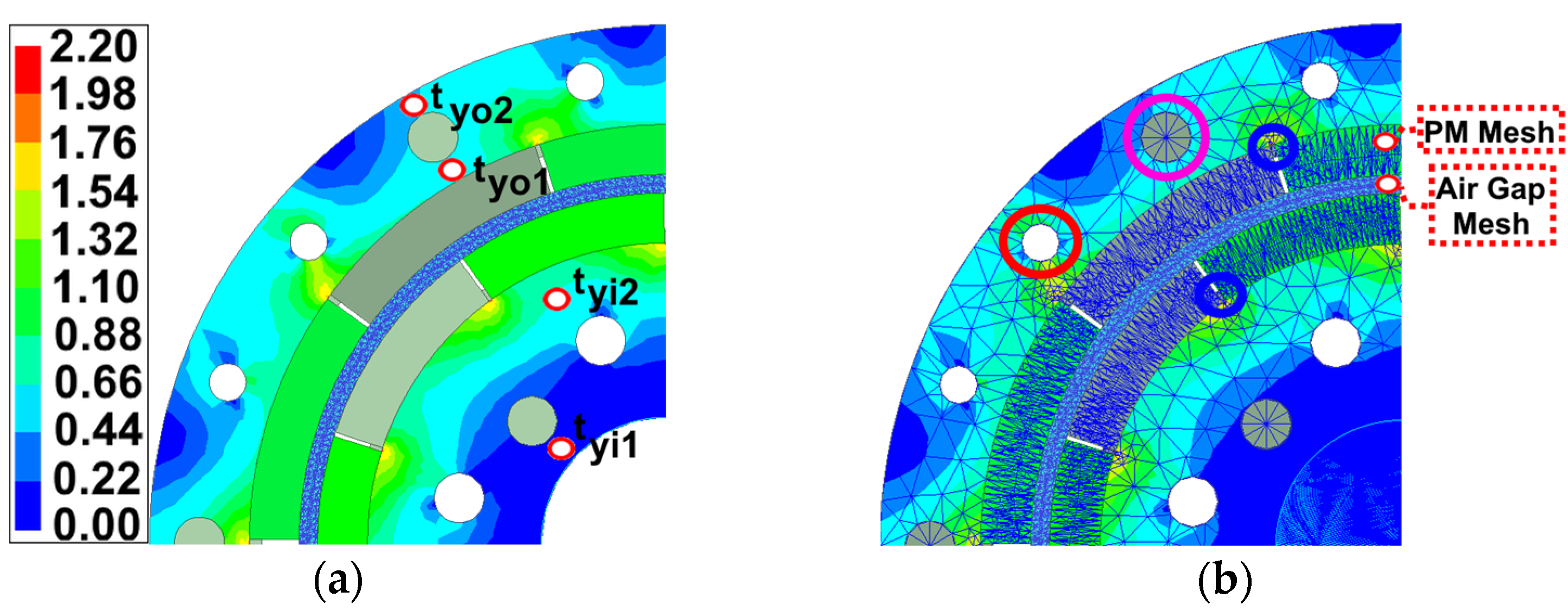
3.3.3. Rotor Flux Density and Mesh Distribution

The flux density of the rotor yokes should be close to, but not reach, the saturation point, which is the knee point on the BH curve to achieve the maximum torque density, as shown in Figure 15a. However, the minimum wall thickness required to prevent material deformation during manufacturing and dynamic effects limits the design of the yoke thickness close to the saturation point. The yoke design is based on adjusting the yoke thicknesses as close as possible to the saturation point, as shown in Figure 15a. In this case, the outer rotor yoke thicknesses (tyo2 and tyo1) can be a minimum of 2 mm to prevent fabrication deformation. The inner rotor inner yoke thickness (tyi1) is set to a minimum of 2.5 mm to avoid reducing the mechanical strength and flywheel effect, and the inner rotor outer yoke thickness (tyi2) is set to 5.24 mm to ensure the selected effective air gap diameter.
Figure 15b exhibits the mesh distribution of the model. The critical regions, such as the air gap and PMs, are subjected to dense meshing. The total number of mesh elements is 9440. The mesh method is TAU. Thus, the solution accuracy is increased. The parts marked in pink are the mounting holes. The diameter of the weight reduction holes, marked in red, is chosen to not reduce the mechanical strength. Thus, the total weight is reduced by 4 gr.

3.3.4. Investigation of Negative Torque at Loss of Synchronisation

Loss of synchronisation (LoS) refers to the situation where the synchronisation between the rotors is disrupted by exceeding the torque limit and critical torque angle as a result of a shaft malfunction on the PE shaft. However, in the case of LoS, while the drive system is sustained by S/G, the negative torque acting from the inner rotor needs to be analysed and accounted for in the safety factor to identify the power limits of the S/G.
In the 2D simulation, the LoS torque is analysed by setting the inner rotor speed to 0 rpm and rotating the outer rotor at different speeds. In the test system, the LoS torque is measured by locking the inner rotor so that it cannot rotate and gradually rotating the outer rotor at different speeds by a speed source. As shown in Figure 16, the LoS torque at the maximum speed is −0.61 N·m for the 2D simulation and −0.6 N·m for the test results. The deviations in the results are due to the sensitivity of the sensors on the test bench and the higher moment of inertia of the test bench compared to the UAV dynamic model in the simulations.

3.4. Maxwell 3D Static and Transient Optimetric Analyses

Static simulations examine the MC behaviour in the steady state, i.e., when the inner or outer rotor shaft is locked. Therefore, model losses are not considered in the static analyses. On the other hand, transient analysis is more accurate because it considers losses, coupling effects, end effects, eddy-current losses on PMs, and material wall thickness.

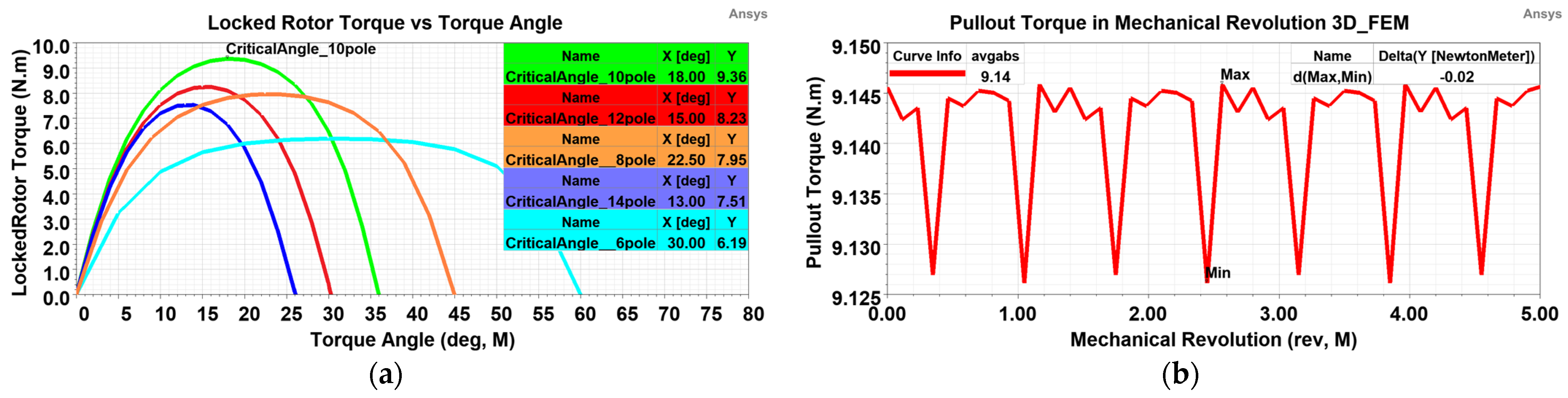
3.4.1. Static Locked-Rotor Torque and Transient Torque Ripple Analyses

Locked-rotor or static torque refers to the torque capability of the coupler. It can be examined in different pole numbers depending on the torque angle, as shown in Figure 17a. The maximum static torque is provided as 9.4 N·m in the 10-pole configuration.
In the dynamic state, torque transmission in response to instantaneous load variations causes torque ripple in MCs due to the different moments of inertia of the rotors and the flywheel effect. It is 20 mN·m for the proposed model, as shown in Figure 17b. The rotors hold each other until the critical angle is exceeded, resulting in minimal torque ripple in the active MCs.

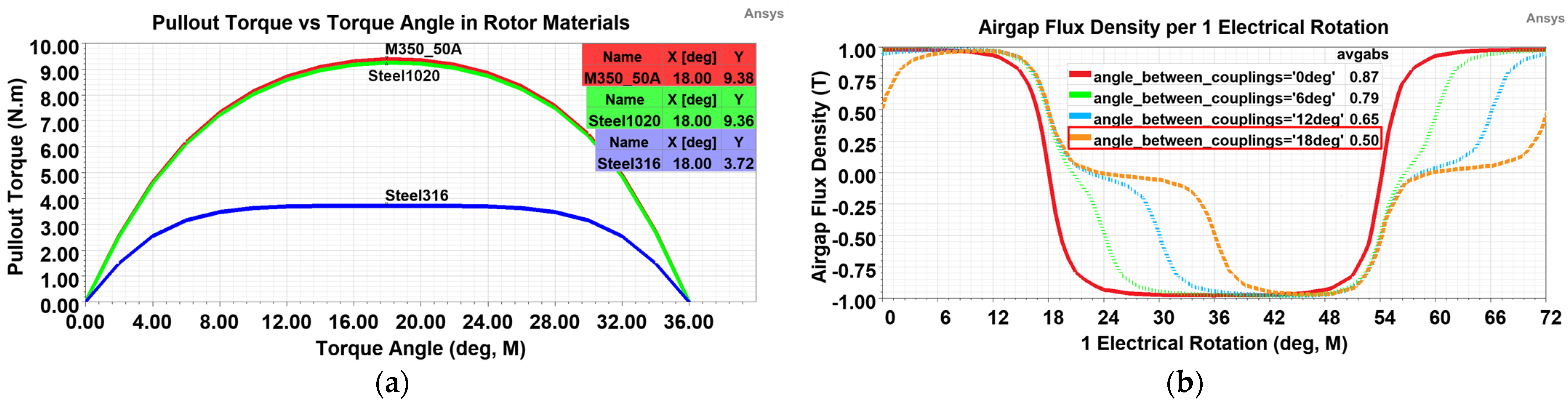
3.4.2. Investigation of Different Rotor Materials and Air Gap Flux Density

Carbon steel, electric steel, and stainless steel can be used as rotor materials. Although electrical steel has lower core losses for synchronous MCs, it does not provide an advantage in the proposed model due to its low model volume. Moreover, the design results in a higher yoke thickness due to the lower saturation point if electrical steel is preferred.
However, some exceptional cases, such as military applications, require the use of nonmagnetic materials, such as Steel-316, called yokeless design. In such cases, it is inevitable to increase the PM thickness to avoid a drastic drop in the torque of approximately 60%, as shown in Figure 18a. Steel-1020 is used as the rotor material in the production of MCs.
On the other hand, the air gap flux density in the air gap is examined in Figure 18b when magnetic Steel-1020 is used as the rotor material. It is 0.5 T at the critical angle of 18 Mdeg for the proposed design, which is far from the demagnetisation point of the PMs.

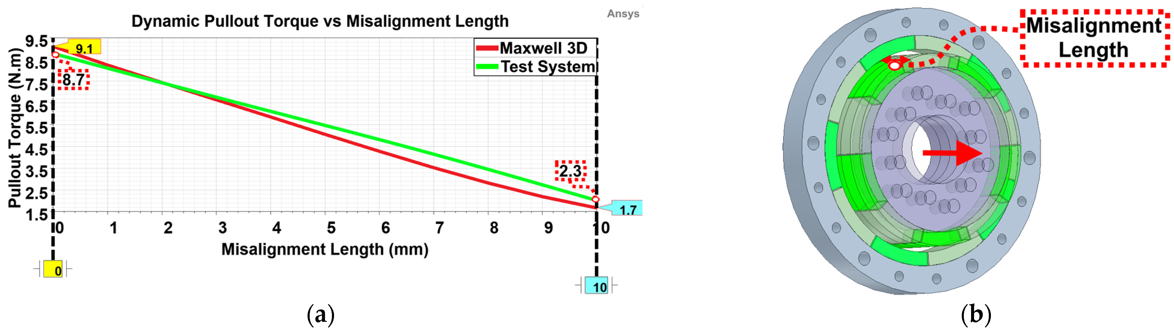
3.4.3. Study of Pullout Torque Depending on Misalignment Length

As part of the worst-case scenario analysis, it is essential to examine the reduction in the pullout torque due to the misalignment length caused by the propeller pulling the system forwards until it is unable to generate thrust in the event of any extreme bearing failure.
Figure 19a examines the pullout torque depending on the misalignment. Figure 19b exhibits the misalignment. The torque decreases as the misalignment increases. Although the test results and the simulations agree with each other, the differences in the results are due to the difficulty in the precision adjustment of the misalignment length in the test system.

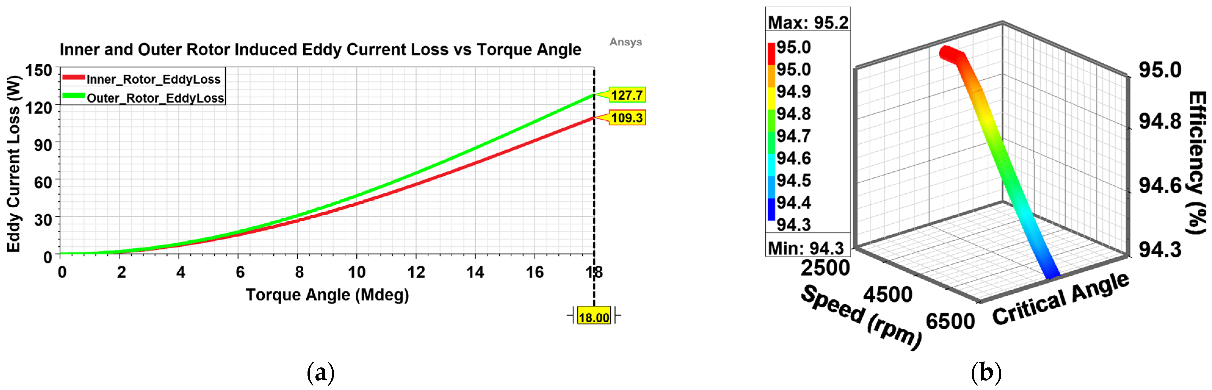
3.4.4. Magnetic Coupler Efficiency and Induced Eddy-Current Losses on PMs

Magnetic coupler losses are composed of rotor core losses, induced eddy-current losses on PMs, and mechanical losses. The mechanical losses, estimated at 3.5% of the output power, are thus calculated as 0.00051 W/(rad/s)2. On the other hand, vibration due to the natural operation of the PE, load disturbances due to different UAV operating zones, and torque fluctuations during load changes cause the torque angle to change continuously. As a result, high eddy-current losses are induced on the PMs, which increase the temperature of the PMs and reduce the transmitted torque by reducing their residual flux density, and their impact on the system should be investigated. The proposed MC design is realised in light of all these effects and the design requirements are provided.
As seen in Figure 20a, the eddy-current losses are simulated as 237 W. The efficiency of the MC is 94.3% at the maximum speed of 6500 rpm and 95% at the minimum speed of 2500 rpm, as shown in Figure 20b at the critical angle. However, to measure the efficiency on the test bench, a second transmitter is required to measure the input power in addition to the torque/speed transmitter measuring the output power. Due to the difficulty in the setup, the efficiency cannot be measured on the test bench. However, using the proposed correction coefficient, the actual efficiency can be estimated from the numerical efficiency graph.

3.5. Summary List of Various MC Designs

The various MC designs obtained from the simulations are summarised in Table 3. The optimum design is realised within the system constraints, and the optimum parameters are indicated with an asterisk. The PM thickness is included in the measurement of the inner rotor outer diameter and outer rotor inner diameter. Validation of the multi-objective simulations and the tests sheds light on the safe usability of MCs in hybrid UAVs.

4. Results and Discussion

This section reveals and discusses the test results and compares them with the 2D and 3D simulation data. In an optimisation process, the accuracy of the analyses is determined, and a correction coefficient is proposed based on the correlation between the results.
Various MCs with different design parameters listed in Table 3 have been produced, and some of them are illustrated in Figure 21. The upper and lower parts illustrate the outer and inner rotors of the MC, respectively.
Due to the MCs being included in the group of noncontact electrical machines [57], their performance examinations are carried out in a similar way to special rotating machines, using direct or indirect test methods [58]. On the other hand, the propulsion platform, including the PE, MC, and propeller, is set up to conduct force tests on the system.
The direct test method provides more accurate results because it dynamically measures MC parameters such as the output torque and output speed with a torque/speed transmitter. Figure 22a demonstrates the installation of the MC for the direct dynamic test system, while Figure 22b shows its installation on the PE and propeller.
The operation principle of the direct dynamic test system shown in Figure 23a is as follows: The MC (3) device under test (D.U.T) is driven by a geared induction motor (4) with a high torque capacity. Dynamic tests are performed by gradually or directly loading the hysteresis brake for 1 h for each set of tests (1), depending on the type of test, such as no-load, rated-load, or overload. At this stage, as the load changes, the output torque and speed are measured by the torque/speed transmitter (2) and recorded by the panel.
In the thrust test system shown in Figure 23b, the load cells and sensors are used to measure the force, thrust, and temperature while the PE is operated at idle speed, cruising speed, and overspeed. The sensors and transducers in the test systems are calibrated by an organisation with an international accreditation certificate [59]. In addition, the tests are performed three times in total at different times, and the average results are used.

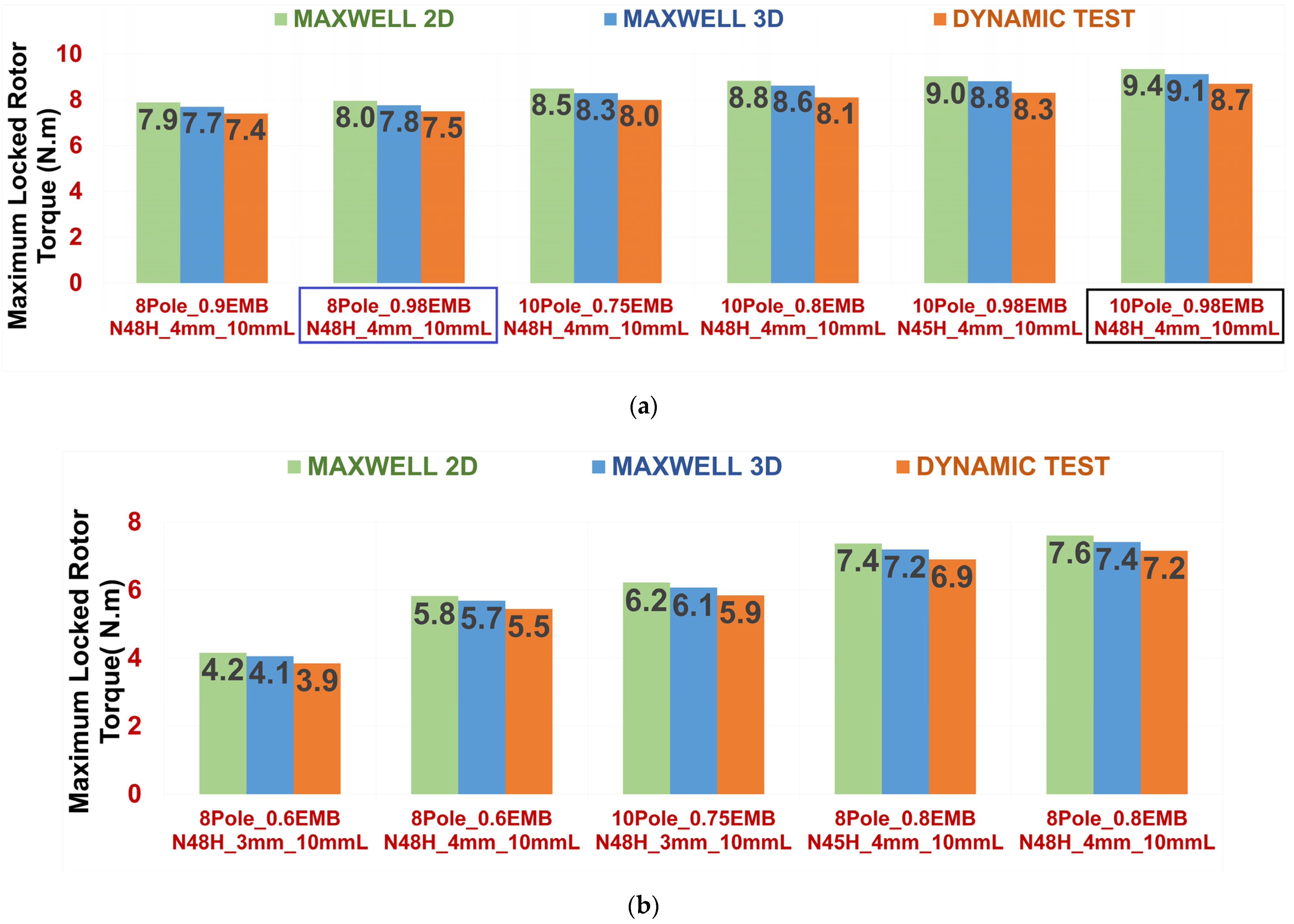
4.1. Locked-Rotor Test Results in Summary

In the locked-rotor or static test, the shaft is heavily loaded by the hysteresis brake so that it cannot be rotated. Depending on the torque angle, torque measurement is performed by gradually adjusting the load, and the data are recorded. Figure 24a shows the results of the locked-rotor test at a critical torque angle with a 10 mm coupler length for configurations with a higher torque density, while Figure 24b exhibits the results for a lower torque density. The maximum locked-rotor torque is achieved at the configuration of 10-pole and 0.98-embrace, as marked in black in Figure 24a.
However, the maximum locked-rotor torque for 8 poles with the same configuration as the 10-pole structure results in a reduction of approximately 14%, as marked in blue in Figure 24a. Furthermore, if the effect of the model length is examined, a twofold increase in the length increases the locked-rotor torque by almost a factor of two.

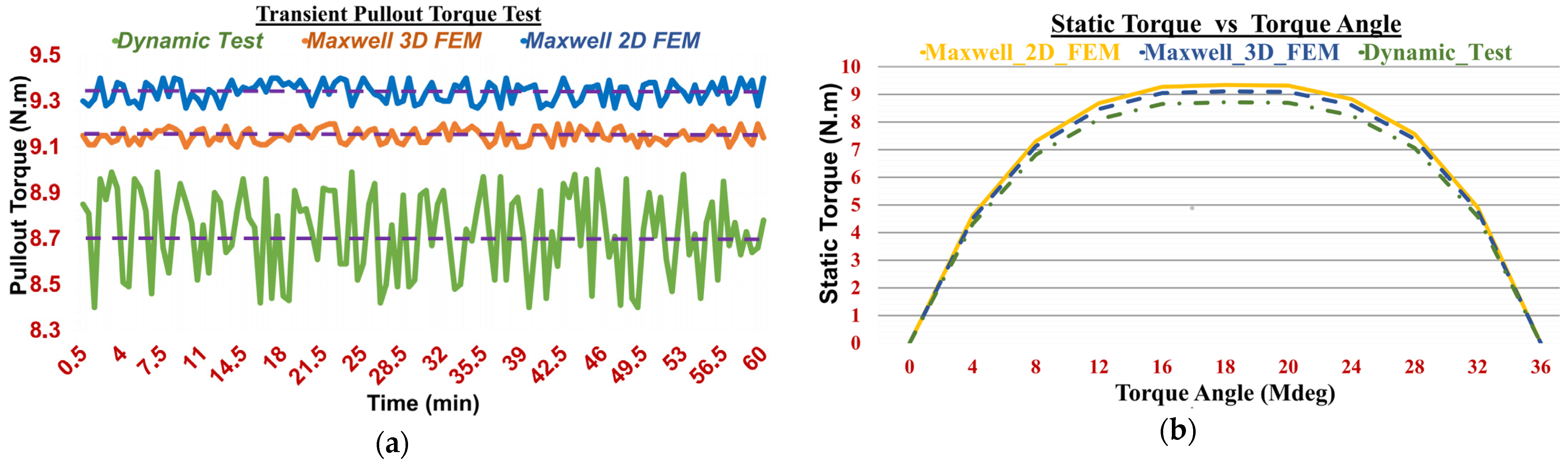
4.2. Investigation of Pullout Torque in Transient and Static Torque versus Torque Angle

The locked-rotor and dynamic test results are consistent with each other. Therefore, the test results are plotted only for the optimum design with a configuration of 10-pole, 0.98-embrace, and 10 mm length to avoid visual pollution.
Figure 25a compares the results obtained from the Maxwell 2D and 3D simulations and dynamic tests depending on time. The average dynamic pullout torque obtained from the Maxwell 2D and 3D simulations and dynamic tests are 9.35 N·m, 9.15 N·m, and 8.7 N·m, respectively. Figure 25b plots the static torque results for the different torque angles. The maximum static torque obtained from the Maxwell 2D and 3D simulations and static tests at the critical angle of 18 Mdeg are 9.32 N·m, 9.11 N·m, and 8.72 N·m, respectively.
The Maxwell simulations are in close agreement with the test results. The numerical simulations have an acceptable margin of error compared to the test results, which is 8% for the Maxwell 2D and 4.5% for the Maxwell 3D, where the safety factor is not included. A more effective design is achieved if a relevant difference or margin of error, called a correction coefficient, is provided in the first step of the numerical design.
In this sense, taking into account the safety factor [60], the Maxwell 2D and 3D simulations are, on average, 14% and 9% higher than the direct dynamic test results for the proposed model, respectively. As a result, a correction coefficient of 1.2 for the Maxwell 2D and 1.1 for the Maxwell 3D is proposed for the use of MCs in hybrid UAVs.

5. Conclusions

This article contributes to exploring all design parameter effects of active cylindrical MCs with multi-objective simulations based on FEMs. The magnetic design was optimised in Ansys Maxwell using optimetric and tuning tools. Increasing the number of poles results in a maximum torque density only up to a certain point. The highest pullout torque was achieved with the configuration of the 10-pole and 0.98-embrace, offering an 18% higher torque than the 8-pole configuration. Increasing the embrace provides more output torque. A 20% increase in the embrace results in a 7.5% increase in the torque density. Reducing the embrace to less than 0.6 almost halves the output torque. Increasing the offset reduces the transmitted torque by a maximum of 10%. Using PMs with a lower residual flux density reduces the pullout torque. The MCs using Nd-Fe-B PMs provide a higher torque density than the couplers using Sm-Co. A double increase in the air gap length reduces the pullout torque by 13%. The reduction in the PM thickness and yoke thickness significantly reduces the torque density. Operating the MC as close to the saturation point as possible ensures the minimum weight of the system. A direct-type dynamic test system was set up for the transient and locked-rotor tests. A thrust test system was also installed for the force tests of the MC on the PE. Exceeding the critical torque angle causes synchronisation loss between the inner and outer rotors. The torque fluctuation at load changes is approximately 0.25%. The loss of synchronisation torque at the maximum speed is −0.61 N·m. The magnetic coupler efficiency is above 94% at the maximum speed. The Maxwell 2D FEM results are higher than the 3D and dynamic tests, but the results agree with a reasonable margin of error. The test results differ by 8% with the Maxwell 2D results and 4.5% with the Maxwell 3D results. The difference is due to the density differences in the adaptive meshes, the inclusion of end-leakage effects in the 3D FEM, and temperature assignments. As a result, a correction coefficient of 1.2 for the Maxwell 2D and 1.1 for the Maxwell 3D is proposed. A comprehensive examination of the active cylindrical MCs contributes to the use of MCs for other applications such as robotics, hydraulics, automotive, medical, and pumps.

Author Contributions

Conceptualisation, S.A. and I.I.; methodology, S.A.; software, S.A.; validation, I.I. and T.S.N.; formal analysis, T.S.N.; investigation, S.A.; resources, I.I.; data curation, S.A.; writing—original draft preparation, S.A.; writing—review and editing, I.I.; visualisation, T.S.N.; supervision, I.I.; project administration, S.A.; funding acquisition, S.A. All authors have read and agreed to the published version of the manuscript.

Funding

This work in part is supported by The Scientific and Technological Research Council of TURKIYE (TUBITAK) 1501 support program with project number 3192296.

Institutional Review Board Statement

Not applicable.

Informed Consent Statement

Not applicable.

Data Availability Statement

Not applicable.

Acknowledgments

FEM is conducted with the licenced use of Ansys Electronics v2020R1. The 3D models are held with the licenced use of Solidworks software.

Conflicts of Interest

The authors declare no conflict of interest.

References

  1. Arslan, S.; Iskender, I.; Navruz, T.S. Optimal Design of an In-Runner Direct-Drive Synchronous Permanent Magnet Starter/Generator for UAVs. In Proceedings of the 2022 International Symposium on Multidisciplinary Studies and Innovative Technologies (ISMSIT), Ankara, Turkey, 20–22 October 2022; pp. 543–548. [Google Scholar] [CrossRef]
  2. Griffo, A.; Wrobel, R.; Mellor, P.H.; Yon, J.M. Design and Characterization of a Three-Phase Brushless Exciter for Aircraft Starter/Generator. IEEE Trans. Ind. Appl. 2013, 49, 2106–2115. [Google Scholar] [CrossRef]
  3. Ose-Zala, B.; Pugachov, V. The comparison of active and reactive magnetic couplers. In Proceedings of the 2012 Electric Power Quality and Supply Reliability, Tartu, Estonia, 11–13 June 2012; pp. 1–4. [Google Scholar] [CrossRef]
  4. Carpentier, A.; Galopin, N.; Chadebec, O.; Meunier, G.; Guérin, C. Application of the virtual work principle to compute magnetic forces with a volume integral method. Int. J. Numer. Model. Electron. Netw. Devices Fields 2013, 27, 418–432. [Google Scholar] [CrossRef]
  5. Li, K.; Bird, J.Z.; Acharya, V.M. Ideal Radial Permanent Magnet Coupling Torque Density Analysis. IEEE Trans. Magn. 2017, 53, 1–4. [Google Scholar] [CrossRef]
  6. Ravaud, R.; Lemarquand, G.; Lemarquand, V.; Depollier, C. Torque in permanent magnet couplings: Comparison of uniform and radial magnetization. J. Appl. Phys. 2009, 105, 053904. [Google Scholar] [CrossRef]
  7. Akcay, Y.; Giangrande, P.; Tweedy, O.; Galea, M. Fast and Accurate 2D Analytical Subdomain Method for Coaxial Magnetic Coupling Analysis. Energies 2021, 14, 4656. [Google Scholar] [CrossRef]
  8. Eker, M.; Özsoy, M. Investigation of the effect of demagnetization fault at Line Start AF-PMSM with FEM. Acad. Platf. J. Eng. Smart Syst. 2022, 10, 94–100. [Google Scholar] [CrossRef]
  9. Ziolkowski, M.; Brauer, H. Fast Computation Technique of Forces Acting on Moving Permanent Magnet. IEEE Trans. Magn. 2010, 46, 2927–2930. [Google Scholar] [CrossRef]
  10. Ose-Zala, B.; Onzevs, O.; Pugachov, V. Formula Synthesis of Maximal Mechanical Torque on Volume for Cylindrical Magnetic Coupler. Electr. Control. Commun. Eng. 2013, 3, 37–43. [Google Scholar] [CrossRef]
  11. Kang, H.-B.; Choi, J.-Y. Parametric Analysis and Experimental Testing of Radial Flux Type Synchronous Permanent Magnet Coupling Based on Analytical Torque Calculations. J. Electr. Eng. Technol. 2014, 9, 926–931. [Google Scholar] [CrossRef]
  12. Ose, B.; Pugachov, V. The Influence of Pole Pair Number and Magnets’ Width on Mechanical Torque of Magnetic Coupler with Rounded Permanent Magnets. Sci. J. Riga Tech. Univ. Power Electr. Eng. 2011, 28, 63–66. [Google Scholar] [CrossRef]
  13. Meng, G.Y.; Niu, Y.H. The Torque Research for Permanent Magnet Coupling Based on Ansoft Maxwell Transient Analysis. Appl. Mech. Mater. 2013, 423, 2014–2019. [Google Scholar] [CrossRef]
  14. Wang, J.; Lin, H.; Fang, S.; Huang, Y. A General Analytical Model of Permanent Magnet Eddy Current Couplings. IEEE Trans. Magn. 2014, 50, 1–9. [Google Scholar] [CrossRef]
  15. Kang, H.-B.; Choi, J.-Y.; Cho, H.-W.; Kim, J.-H. Comparative Study of Torque Analysis for Synchronous Permanent Magnet Coupling with Parallel and Halbach Magnetized Magnets Based on Analytical Field Calculations. IEEE Trans. Magn. 2014, 50, 1–4. [Google Scholar] [CrossRef]
  16. Lubin, T.; Mezani, S.; Rezzoug, A. Simple Analytical Expressions for the Force and Torque of Axial Magnetic Couplings. IEEE Trans. Energy Convers. 2012, 27, 536–546. [Google Scholar] [CrossRef]
  17. Ge, Y.-J.; Nie, C.-Y.; Xin, Q. A three dimensional analytical calculation of the air-gap magnetic field and torque of coaxial magnetic gears. Prog. Electromagn. Res. 2012, 131, 391–407. [Google Scholar] [CrossRef]
  18. Niu, S.; Mao, Y. A Comparative Study of Novel Topologies of Magnetic Gears. Energies 2016, 9, 773. [Google Scholar] [CrossRef]
  19. Jian, L.; Chau, K.-T. Analytical calculation of magnetic field distribution in coaxial magnetic gears. Prog. Electromagn. Res. 2009, 92, 1–16. [Google Scholar] [CrossRef]
  20. Chau, K.T.; Zhang, D.; Jiang, J.Z.; Liu, C.; Zhang, Y. Design of a Magnetic-Geared Outer-Rotor Permanent-Magnet Brushless Motor for Electric Vehicles. IEEE Trans. Magn. 2007, 43, 2504–2506. [Google Scholar] [CrossRef] [Green Version]
  21. Jian, L.; Chau, K.T. Design and analysis of a magnetic-geared electronic-continuously variable transmission system using finite element method. Prog. Electromagn. Res. 2010, 107, 47–61. [Google Scholar] [CrossRef]
  22. Wang, S.; Guo, Y.; Cheng, G.; Li, D. Performance Study of Hybrid Magnetic Coupler Based on Magneto Thermal Coupled Analysis. Energies 2017, 10, 1148. [Google Scholar] [CrossRef]
  23. Zheng, D.; Wang, D.; Li, S.; Shi, T.; Li, Z.; Yu, L. Eddy current loss calculation and thermal analysis of axial-flux permanent magnet couplers. AIP Adv. 2017, 7, 025117. [Google Scholar] [CrossRef]
  24. Min, K.-C.; Choi, J.-Y.; Kim, J.-M.; Cho, H.-W.; Jang, S.-M. Eddy-Current Loss Analysis of Noncontact Magnetic Device with Permanent Magnets Based on Analytical Field Calculations. IEEE Trans. Magn. 2015, 51, 1–4. [Google Scholar] [CrossRef]
  25. Ose-Zala, B.; Jakobsons, E.; Suskis, P. The use of Magnetic Coupler instead of Lever Actuated Friction Clutch for Wind Plant. Elektron. Elektrotechnika 2012, 18, 13–16. [Google Scholar] [CrossRef]
  26. Li, Y.; Hu, Y.; Song, B.; Mao, Z.; Tian, W. Performance Analysis of Conical Permanent Magnet Couplings for Underwater Propulsion. J. Mar. Sci. Eng. 2019, 7, 187. [Google Scholar] [CrossRef]
  27. Chau, K.T.; Jiang, C.; Han, W.; Lee, C.H.T. State-of-the-art electromagnetics research in electric and hybrid vehicles (invited paper). Prog. Electromagn. Res. 2017, 159, 139–157. [Google Scholar] [CrossRef]
  28. Saleh, K.; Sumner, M. Sensorless Speed Control of Five-Phase PMSM Drives in Case of a Single-Phase Open-Circuit Fault. Iran. J. Sci. Technol. Trans. Electr. Eng. 2019, 43, 501–517. [Google Scholar] [CrossRef]
  29. Niemenmaa, A.; Salmia, L.; Arkkio, A.; Saari, J. Modeling Motion, Stiffness, and Damping of a Permanent-Magnet Shaft Coupling. IEEE Trans. Magn. 2010, 46, 2763–2766. [Google Scholar] [CrossRef]
  30. Krasilnikov, A.Y.; Krasilnikov, A.A. Calculation of losses in current-conducting screen in sealed machines and devices due to loose packing of magnets in half-clutches of magnetic clutch. Chem. Pet. Eng. 2011, 47, 392–397. [Google Scholar] [CrossRef]
  31. Mei, Y.; Luo, J. Influence of Eccentric Arc Design at the Rotor on the Electromagnetic Performance of a Permanent-Magnet Synchronous Motor. Iran. J. Sci. Technol. Trans. Electr. Eng. 2022. [Google Scholar] [CrossRef]
  32. Fontchastagner, J.; Lefevre, Y.; Messine, F. Some Co-Axial Magnetic Couplings Designed Using an Analytical Model and an Exact Global Optimization Code. IEEE Trans. Magn. 2009, 45, 1458–1461. [Google Scholar] [CrossRef]
  33. Kim, S.H.; Shin, J.W.; Ishiyama, K. Magnetic Bearings and Synchronous Magnetic Axial Coupling for the Enhancement of the Driving Performance of Magnetic Wireless Pumps. IEEE Trans. Magn. 2014, 50, 1–4. [Google Scholar] [CrossRef]
  34. Cao, W.; Mecrow, B.C.; Atkinson, G.J.; Bennett, J.W.; Atkinson, D.J. Overview of Electric Motor Technologies Used for More Electric Aircraft (MEA). IEEE Trans. Ind. Electron. 2012, 59, 3523–3531. [Google Scholar] [CrossRef]
  35. Zareb, M.; Nouibat, W.; Bestaoui, Y.; Ayad, R.; Bouzid, Y. Evolutionary Autopilot Design Approach for UAV Quadrotor by Using GA. Iran. J. Sci. Technol. Trans. Electr. Eng. 2020, 44, 347–375. [Google Scholar] [CrossRef]
  36. Benarous, M.; Trezieres, M. Design of a cost-effective magnetic gearbox for an aerospace application. J. Eng. 2019, 2019, 4081–4084. [Google Scholar] [CrossRef]
  37. Charpentier, J.; Lemarquand, G. Calculation of ironless permanent magnet couplings using semi-numerical magnetic pole theory method. COMPEL-Int. J. Comput. Math. Electr. Electron. Eng. 2001, 20, 72–89. [Google Scholar] [CrossRef]
  38. Singh, R.; Lal, R.; Singari, R.; Chaudhary, R. Failure of Piston in IC Engines: A Review. Int. J. Mod. Eng. Res. 2014, 4, 1–10. [Google Scholar]
  39. Moosavian, A.; Najafi, G.; Ghobadian, B.; Mirsalim, M. The effect of piston scratching fault on the vibration behavior of an IC engine. Appl. Acoust. 2017, 126, 91–100. [Google Scholar] [CrossRef]
  40. 3W-Modellmotoren GmbH Home Page. Available online: https://3w-modellmotoren.de/produkt/bearcat-f8f-blau/?lang=en (accessed on 29 January 2023).
  41. IEEE. IEEE Approved Draft Trial-Use Guide for Testing Permanent Magnet Machines. In IEEE P1812/D5; IEEE: New York, NY, USA, 2014; pp. 1–65. [Google Scholar]
  42. Yang, X.; Pei, X. 15—Hybrid system for powering unmanned aerial vehicles: Demonstration and study cases. In Hybrid Energy Systems Hybrid Technologies for Power Generation; Elsevier: Amsterdam, The Netherlands, 2022; pp. 439–473. [Google Scholar] [CrossRef]
  43. Valavanis, K.P.; Vachtsevanos, G.J. Handbook of Unmanned Aerial Vehicles; Springer: Berlin/Heidelberg, Germany, 2014. [Google Scholar]
  44. Easy Access Rules for Unmanned Aircraft Systems (Regulations (EU) 2019/947 and 2019/945). Official Journal of the European Union. 2022. Available online: https://www.easa.europa.eu/en/downloads/110913/en (accessed on 29 January 2023).
  45. Ose-Zala, B. Design Optimization of Cylindrical Magnetic Coupler Based on Calculations of Magnetic Field. Ph.D. Thesis, Department of Power and Electrical Engineering, Riga Technical University, Riga, Latvia, 2015. [Google Scholar]
  46. Suti, A.; Di Rito, G.; Galatolo, R. Fault-Tolerant Control of a Dual-Stator PMSM for the Full-Electric Propulsion of a Lightweight Fixed-Wing UAV. Aerospace 2022, 9, 337. [Google Scholar] [CrossRef]
  47. Quattrocchi, G.; Berri, P.C.; Vedova, M.D.L.D.; Maggiore, P. An Improved Fault Identification Method for Electromechanical Actuators. Aerospace 2022, 9, 341. [Google Scholar] [CrossRef]
  48. Akcay, Y.; Giangrande, P.; Galea, M. A Novel Magnetic Coupling Configuration for Enhancing the Torque Density. In Proceedings of the 23rd International Conference on Electrical Machines and Systems (ICEMS), Hamamatsu, Japan, 24–27 November 2020; pp. 228–233. [Google Scholar] [CrossRef]
  49. Ravaud, R.; Lemarquand, V.; Lemarquand, G. Analytical Design of Permanent Magnet Radial Couplings. IEEE Trans. Magn. 2010, 46, 3860–3865. [Google Scholar] [CrossRef]
  50. Bossavit, A. Virtual power principle and Maxwell’s tensor: Which comes first? COMPEL Int. J. Comput. Math. Electr. Electron. Eng. 2011, 30, 1804–1814. [Google Scholar] [CrossRef]
  51. Yonnet, J.-P.; Hemmerlin, S.; Rulliere, E.; Lemarquand, G. Analytical calculation of permanent magnet couplings. IEEE Trans. Magn. 1993, 29, 2932–2934. [Google Scholar] [CrossRef]
  52. Nagrial, M.H.; Rizk, J.; Hellany, A. Design of synchronous torque couplers. World Acad. Sci. Eng. Technol. Int. J. Mech. Mechatron. Eng. 2011, 5, 1319–1324. [Google Scholar] [CrossRef]
  53. Lin, W.Y.; Kuan, L.P.; Jun, W.; Han, D. Near-Optimal Design and 3-D Finite Element Analysis of Multiple Sets of Radial Magnetic Couplings. IEEE Trans. Magn. 2009, 44, 4747–4753. [Google Scholar] [CrossRef]
  54. Maxwell Help Overview Statistical Analysis Overview, Release 20.1; Ansys® Electronics: Canonsburg, PA, USA, 2020.
  55. Ose, B.; Pugachov, V.; Orlova, S.; Vanags, J. The influence of permanent magnets’ width and number on the mechanical torque of a magnetic coupler with rectangular permanent magnets. In Proceedings of the 2011 IEEE International Symposium on Industrial Electronics, Gdansk, Poland, 27–30 June 2011; pp. 761–765. [Google Scholar] [CrossRef]
  56. Nachouane, A.B.; Abdelli, A.; Friedrich, G.; Vivier, S. Estimation of Windage Losses inside Very Narrow Air Gaps of High Speed Electrical Machines without an Internal Ventilation Using CFD Methods. In Proceedings of the 2016 XXII International Conference on Electrical Machines (ICEM), Lausanne, Switzerland, 4–7 September 2016. [Google Scholar] [CrossRef]
  57. Suti, A.; Di Rito, G.; Galatolo, R. Novel Approach to Fault-Tolerant Control of Inter-Turn Short Circuits in Permanent Magnet Synchronous Motors for UAV Propellers. Aerospace 2022, 9, 401. [Google Scholar] [CrossRef]
  58. Bojoi, R.; Cavagnino, A.; Miotto, A.; Tenconi, A.; Vaschetto, S. Radial flux and axial flux PM machines analysis for more electric engine aircraft applications. In Proceedings of the 2010 IEEE Energy Conversion Congress and Exposition, Atlanta, GA, USA, 12–16 September 2010; pp. 1672–1679. [Google Scholar] [CrossRef]
  59. Ums Quality Electrical Calibration Co., Ltd. Home Page. Available online: http://www.umsankara.com.tr (accessed on 29 January 2023).
  60. Zipay, J.J.; Modlin, C.T.; Larsen, C.E. The Ultimate Factor of Safety for Aircraft and Spacecraft—Its History, Applications and Misconceptions. In Proceedings of the 57th AIAA/ASCE/AHS/ASC Structures, Structural Dynamics, and Materials Conference, San Diego, CA, USA, 4–8 January 2016. [Google Scholar] [CrossRef] [Green Version]
Figure 1. Simple hybrid UAV illustration with the Sullivan S676 Starter/Generator.
Aerospace 10 00140 g001
Figure 2. Type of MCs: (a) Active/Reactive coupler; (b) Hysteresis coupler; (c) Eddy-current coupler.
Aerospace 10 00140 g002
Figure 3. (a) Block diagram of the hybrid UAV; (b) 3D drawing of the proposed model.
Aerospace 10 00140 g003
Figure 4. Mounting illustration of the (a) Inner rotor; (b) Inner flange.
Aerospace 10 00140 g004
Figure 5. Rotor topologies: (a) Arc surface-mounted; (b) Rectangular surface-mounted; (c) Ring-type; (d) Buried arc type; (e) Buried type; (f) Inset type; (g) Halbach arrays; (h) Enhanced hybrid.
Aerospace 10 00140 g005
Figure 6. Model of the MCs (a) Parameter definitions for the VM method; (b) Material definitions.
Aerospace 10 00140 g006
Figure 7. Pullout torque versus (a) Effective air gap length in model length; (b) Model length.
Aerospace 10 00140 g007
Figure 8. (a) Torque vs same rotor pole number; (b) Torque density vs different rotor pole number.
Aerospace 10 00140 g008
Figure 9. Pullout torque investigation versus: (a) Pole number in air gap length; (b) Air gap length.
Aerospace 10 00140 g009
Figure 10. Inner and outer rotor PM thickness versus: (a) Torque density; (b) Coupler weight.
Aerospace 10 00140 g010
Figure 11. Pullout torque versus: (a) Thickness of inner yoke; (b) Thickness of outer yoke.
Aerospace 10 00140 g011
Figure 12. Pullout torque versus: (a) PM embrace; (b) PM offset.
Aerospace 10 00140 g012
Figure 13. Pole types versus: (a) Type-1; (b) Type-2; (c) Type-3; (d) Torque density in rev,M.
Aerospace 10 00140 g013
Figure 14. Effect of PM: (a) Grade; (b) Type; (c) Magnetic orientation; (d) Operating temperature.
Aerospace 10 00140 g014
Figure 15. (a) Flux density distributions; (b) Mesh distributions.
Aerospace 10 00140 g015
Figure 16. Negative torque at loss of synchronisation depending on operating speed.
Aerospace 10 00140 g016
Figure 17. (a) Locked-rotor torque versus torque angle; (b) Torque ripple in mechanical revolution.
Aerospace 10 00140 g017
Figure 18. Investigation of: (a) Effect of different rotor materials on torque; (b) Air gap flux density.
Aerospace 10 00140 g018
Figure 19. (a) Pullout torque depending on misalignment length; (b) Exhibition of misalignment.
Aerospace 10 00140 g019
Figure 20. (a) Induced eddy-current losses on PMs; (b) Efficiency of the MC at maximum speed.
Aerospace 10 00140 g020
Figure 21. Various MC productions of: (a) 8-pole/0.8-embrace/3 mm-PM thickness/10 mm length; (b) 8-pole/0.98-embrace/4 mm-PM thickness/10 mm length; (c) 10-pole/0.8-embrace/4 mm-PM thickness/10 mm length; (d) 10-pole/0.98-embrace/4 mm-PM thickness/10 mm length; (e) 10-pole/0.98-embrace/4 mm-PM thickness/20 mm length.
Aerospace 10 00140 g021
Figure 22. Assembly of (a) MC for dynamic tests; (b) MC with piston engine and propeller.
Aerospace 10 00140 g022
Figure 23. Test system of: (a) Direct dynamic method; (b) Thrust measurement method.
Aerospace 10 00140 g023
Figure 24. Locked-rotor test results of: (a) Higher torque density; (b) Lower torque density.
Aerospace 10 00140 g024
Figure 25. Test results of the optimum MC in the 10-pole, 0.98-embrace, and 10 mm length configuration: (a) Pullout torque in transients; (b) Static torque versus torque angle in magnetostatics.
Aerospace 10 00140 g025
Table 1. Design parameters.
ParametersValue
Pullout torque, with safety factor and correction coefficient6.9 N·m
Minimum torque density, required18.4 N·m/kg
Rated speed4500 rpm
Operation speed range2500–6500 rpm
Table 2. Analytical design calculations by virtual work approach for preliminary sizing.
Design Outputs10-Pole
Air gap volume, minimum required1289.5 mm3
Length of the model, based on rmean5 mm
(θ-dθ), dθ at critical torque angle0.314 rad.
Critical torque angle18 (°M)
Design Assumptions
Middle of the air gap radius, rmean27.5 mm
Average air gap flux density0.65 T
Air gap length1.5 mm
Pullout torque, required6.9 N·m
Table 3. Dimension and performance list of various MCs in summary.
Pole Number8-Pole10-Pole *
Embrace0.60.80.980.80.98 *
PM Thickness3 mm4 mm4 mm4 mm *
Grade of PMN48HN45HN48HN48HN48H *
Outer diameter of outer rotor79 mm83 mm83 mm *
Inner diameter of outer rotor57 mm59 mm59 mm *
Outer diameter of inner rotor54 mm56 mm56 mm *
Inner diameter of inner rotor20 mm20 mm20 mm *
Air gap length1.5 mm1.5 mm1.5 mm *
Effective air gap diameter55.5 mm57.5 mm57.5 mm *
Model length10 mm10 mm10 mm *
Total weight (gr)320350351370352371
Pullout torque (N·m), dynamic3.96.97.27.58.18.7
Torque density (N·m/kg)12.219.720.520.32323.45
* Optimum values.
Disclaimer/Publisher’s Note: The statements, opinions and data contained in all publications are solely those of the individual author(s) and contributor(s) and not of MDPI and/or the editor(s). MDPI and/or the editor(s) disclaim responsibility for any injury to people or property resulting from any ideas, methods, instructions or products referred to in the content.

