Article

Optimization of the Wire Diameter Based on the Analytical Model of the Mean Magnetic Field for a Magnetically Driven Actuator

School of Mechanical Engineering and Automation, Fuzhou University, Fuzhou 350116, China
*
Author to whom correspondence should be addressed.
Aerospace 2023, 10(3), 270; https://doi.org/10.3390/aerospace10030270
Submission received: 26 December 2022 / Revised: 7 March 2023 / Accepted: 8 March 2023 / Published: 10 March 2023

Abstract

:
A magnetic field induced by an electromagnetic coil is the key variable that determines the performance of a magnetically driven actuator. The applicability of the empirical models of the coil turns, static resistance, and inductance were discussed. Then, the model of the mean magnetic field induced by the coil was established analytically. Based on the proposed model, the sinusoidal response and square-wave response were calculated with the wire diameter as the decision variable. The amplitude and phase lag of the sinusoidal response, the time-domain response, steady-state value, and the response time of the square-wave response were discussed under different wire diameters. From the experimental and computational results, the model was verified as the relative errors were acceptably low in computing various responses and characteristic variables. Additionally, the optimization on the wire diameter was carried out for the optimal amplitude and response time. The proposed model will be helpful for the analytical analysis of the mean magnetic field, and the optimization result of the wire diameter under limited space can be employed to improve the performance of a magnetically driven actuator.

1. Introduction

The magnetically driven actuator has been widely used in plenty of engineering fields, including vibration reduction or control, ultra-precision machining, acting fluidic valves, etc. [1,2,3,4]. Magnetically driven actuators have also been introduced to quite commonly actuate an aerospace device [5,6,7,8,9,10,11,12,13,14,15], including the electro-hydraulic servo valve.
Optimization of the actuator is quite important to improve the actuator’s performance. A magnetic field was generally chosen as the optimization objective function as it influences the output performance of the actuator directly, and is the simplest variable to optimize the actuator, compared to the magnetization/magnetic induction intensity or the displacement. Taking the giant magnetostrictive actuator which employs the giant magnetostrictive material (GMM) as its actuation core as an example, Figure 1 summarizes the generally used optimization methods. From the point of view of magnetic fields, the optimization of actuator performance was generally converted to the promotion of the mean magnetic field in the GMM area, which is equivalent to the maximization of the magneto motive force (MMF) distributed on GMM. Additionally, two methods were used to promote the MMF on GMM, respectively, improving the MMF ratio occupied by GMM and increasing the total MMF.
The first optimization method was accomplished based on some magnetic field models from a “field” or “circuit” method [16,17,18,19]. Liang Yan et al. [20] and HyoYoung Kim et al. [21] proposed a mathematic model based on the Biot–Savart law and the finite element model to formulate the three-dimensional magnetic field distribution in a spherical actuator. Abdul Ghani Olabi et al. [22] also established the finite element model of a magnetostrictive actuator for analyzing the magnetic field in the actuator. The proposed models supplied the mean values and distribution characters of magnetic devices, which were quite helpful for the magnetic circuit optimization. Due to the complex magnetic circuit of the hybrid excitation generator used in an energy conversion system, Huihui Geng et al. [23] proposed an analytical method of the main magnetic field, where the Carter coefficient and rotor magnetomotive force were taken as the objective variables. Compared with traditional methods, the proposed method can improve the accuracy of the outputted magnetic field. Jaewook Lee et al. [24] adopted a simplified finite element model to execute structural topology optimization for the high magnetic force of a linear actuator, and they found that the use of a periodic ladder structure was best for magnetic field manipulation. Kim Tien, Xulei Yang et al. [14,25] utilized the finite element model to analyze the distribution of the magnetic field in a giant magnetostrictive actuator separately. By adjusting the permeability of the parts appropriately, the uniformity and mean intensity of the magnetic field within the material could be improved. Some other modeling and optimizing methods for the magnetic field within specified structures can also supply effective references [17,26,27,28,29]. On the whole, the circuit model was always used to form a magnetic field model for an analytical analysis. The finite element model [19,30,31] was commonly used to promote magnetic field uniformity. For the mean magnetic field applied to the giant magnetostrictive material, the positively proportional model vs. the coil current [1,2,3,16,19,28,32,33,34,35] was quite commonly used. Then, the closed circuit was verified to be helpful for higher magnetic field intensity [15] as it improved the proportional factor.
Figure 1. Generally used optimization methods for the giant magnetostrictive actuator: Refs. [16,17,18,19,20,21,22,23,24,25,26,27,28,29,30,31] based on the first method and Refs. [36,37,38,39,40,41,42,43,44] based on the second one.
Aerospace 10 00270 g001
For the second optimization method, an appropriate voltage waveform or the winging method was considered to directly promote the total MMF and the magnetic field induced by a coil [2]. A high threshold with a low-holding voltage has been widely used in an electromagnetic injector. C.B. Britht et al. [36] and G. Xue et al. [37,38] introduced this type of voltage to stimulate a giant magnetostrictive device. Additionally, it was comprehensively verified that the introduced voltage promoted the response time of the coil current, and the magnetic field, quite efficiently. Manh Cuong Hoang et al. [39] proposed an optimization method of the magnetic field for an electromagnetic actuation system. The maximum magnetic and gradient fields were significantly enhanced by the proposed algorithm compared to the conventional independent control. Haoying Pang et al. [40] proposed a novel spherical coil for the atomic sensor, where the magnetic field uniformity was improved along the axis. Yiwei Lu et al. [18] introduced the magnetically shielded room to enhance the coil magnetic field and reduce power loss for a multi-coil system. Cooperated with the non-dominated sorting genetic algorithm, the design reached prominent reductions in total current and power loss. Yundong Tang et al. [41] introduced two correcting coils to improve the uniformity of the magnetic field for a solenoid coil, while it was not so convenient when the coil space was limited as the correcting coils should have occupied some axial spaces. Some other optimization methods for the coil or contactor [42,43,44] can also provide useful references for optimizing the magnetic field induced by an electromagnetic coil.
Based on the second optimization method, this paper focuses on coil optimization when the volume of the magnetically driven actuator suitable for an electro-hydraulic servo valve is limited. In this paper, the dynamic magnetic field was tested based on the linear relationship between the magnetic field and coil current. Then, the dimension parameter, static resistance, and static induction were modeled based on empirical equations or mathematical fitting. The mean magnetic field within the coil was modeled, especially its functional relationship with respect to the wire diameter. Then, the sinusoidal and square-wave responses were calculated, and the important characteristic parameters of these responses were extracted. From the calculated and tested results, the influence of the wire diameter on the mean magnetic field was discussed comprehensively for an optimal selection of the wire diameter. During analysis, the relative errors in computing various variables were also given to verify the precision of the proposed model and effectiveness of the optimization. For the magnetically driven actuator, optimized results can be employed to promote the amplitude and response speed of the mean magnetic field, and then to improve the actuator performance.

2. Experimental Methods

2.1. Test Principle

The dynamic magnetic field intensity or magnetic flux density was always measured “indirectly” based on Ampere’s circuital theorem or Faraday’s law of induction. Based on the former principle, the induced magnetic field and coil current have an ideal positive proportion relationship, which has been a commonly used analytical model of the mean magnetic field in some magnetically driven actuators, especially the giant magnetostrictive actuator. Based on this measuring principle, as long as the coil current is measured, the accurate mean of the magnetic field in a dynamic type can be obtained.
The model was easily given by adding a proportional coefficient to the magnetic field model in an infinitely long solenoid [3,5,14,16,19,33,34,35]
H = C H I N I L
where H is the magnetic field intensity and I is the current intensity within the coil, CHI is the proportional coefficient of the mean magnetic field intensity; its value belongs to (0,1), N is the number of the coil turn, and L is the coil length.
The following optimization was based on Equation (1)—the optimization is effective as long as the mean magnetic field in the magnetically driven actuator is in direct proportion to the product of the number of coil turns and current intensity. For a hollow coil, Equation (1) was not only capable of computing the mean magnetic field within homogeneous medium, but was also suitable to the local mean magnetic field as long as the whole magnetic circuit was filled locally uniformly and did not have too many reluctance numbers. Considering Equation (1) is suitable for most giant magnetostrictive actuators and some micro-displacement electromagnetic actuators; the optimization proposed in this paper is suitable to these types of actuators.

2.2. Experiment Setup and Parameters

The experimental system was shown in Figure 2. As illustrated in Figure 2a,c, the computer controlled PS3403D digital oscilloscope (with an embedded signal generator) to generate the required waveform signals. The generated signals were then amplified by an ATA304 power amplifier and inputted into the two ends of the coil. The input voltage at both ends of the coil was differentially collected and the coil current was measured by a TA189A current clamp. The measured voltage and current data were delivered into the digital oscilloscope and then into the computer for processing.
Figure 2b,d supplied the sectional drawing and photograph of the coils, where La, Lb, Lf represented the coil length, coil thickness, and diameter of the skeleton shaft, respectively, and Dwire and Dcore were the enameled wire diameter and copper core diameter, respectively. The coils were tightly wound by the use of standard enameled wires. Since this article focuses on the optimization of the coil itself, it is not necessary to consider the influence of the iron core or other parts in an actuator. The parameters of the coils are given in Table 1, and some necessary parameters of the skeleton and material are supplied in Table 2. Considering the value of CHI does not affect the increasing or decreasing relationship between the variables; CHI will have no effect on the optimization results. CHI is specified as 0.8 here.

3. Data Processing and Analysis

3.1. Inherent Characteristic Parameters of Coils

3.1.1. Dimension Parameters

Standard enameled wire has a nominal diameter of the external wire or the copper core. Then, a certain functional relationship can be supplied between the enameled wire diameter Dwire and the copper core diameter Dcore. Figure 3 shows the actual values of Dwire and Dcore and the fitted results using linear functions. It can be seen from Figure 3 that the diameter of copper core is approximately linear vs. the external diameter of enameled wire. With and without an intercept, the fitted linear equations were determined as Dcore = 0.9687 Dwire − 0.03214 and Dcore = 0.9394 Dwire, respectively. The linear function with an intercept was quite accurate as the relative error was lower than 1.52% when Dwire was higher than 0.3 mm and lower than 2.55 mm. In contrast, the linear function without an intercept was not so accurate since the relative error was higher than 5% under some conditions, especially when Dwire was quite low.
Though the positively proportional relationship was not suitable to a wide range of dimensions, it may be feasible when the Dwire changed within a relatively narrow interval. The coils used in this paper were wound by the wires with diameters of 0.3~0.8 mm. Executing a simple linear fitting, Table 3 supplies the results and relative errors of the two line equations. From computation, the linear equation with intercept was Dcore = 0.962 Dwire − 0.0277 and had a relative error lower than 0.84%. In comparison, the linear equation without an intercept Dcore = 0.898 Dwire also had high precision as the relative error was lower than 3.2%. Thus, it is acceptable to use a positively proportional function to describe the relationship between Dcore and Dwire when Dwire changes within a narrow interval, which is quite convenient for the following optimization.
From the sectional drawing shown in Figure 2b, it can be observed that winding a coil was equivalent to arranging the cross-sectional area of the wire in the rectangular area supplied by the coil skeleton. The coil turns must be an integer; while La or Lb was not exactly the integral multiple of Dwire, the effective length La’ and thickness Lb’ were a little lower than La and Lb, respectively. Coil length or thickness was not fully utilized, and the available area was La’×Lb’, which was slightly less than the actual area.
From Figure 2b, the turn number per layer was L a / D w i r e and the number of layers was L b D w i r e 3 D w i r e / 2 + 1 , so that the accurate value of coil turns was
N = C f L a D w i r e ( L b D w i r e 3 D w i r e / 2 + 1 ) C f ( L a L b 3 D w i r e 2 / 2 0.155 L a D w i r e ) C f L a L b π D w i r e 2 / 4
where Cf′ was introduced to describing the winding effect, Cf was the filling factor of the enameled wire. LaLb was the axis-sectional area of the coil and πDwire2/4 was the cross-sectional area of single enameled wire.
From Equation (2), the assumption that N was positively proportional to the ratio of the cross-sectional area of the coil skeleton to Dwire was conditional. That was, with the effectiveness of Equation (2), determined by the weight of Cf’0.155 La/Dwire in the total coil turns. Additionally, the relative error of the positively proportional function was 0.155/(1.155 Lb/Dwire − 0.155) × 100%, which was determined by Lb/Dwire.
Lb/Dwire determined the number of layers and the relative error, which are displayed in Figure 4. From the calculation results, the relative error of CfLaLb/(πDwire2/4) computing N decreased with Lb/Dwire increasing. To guarantee that the relative error of Equation (2) is lower than 5.0% in computing N, it should be met that Lb > 2.8 Dwire. That is, the coil should be wound with three layers at least. When Lb < 2.8 Dwire, one should use Lb’ = L b D w i r e 3 D w i r e / 2 + 1 instead of Lb for computations. For the coils in this paper, the values of Lb/Dwire under different Dwire were higher than 6.8/0.8 = 8.5 so that the approximate expression in Equation (2) has enough precision.
For convenience, the value of Cf was determined by the mean values of N and Dwire so that Cf = 0.57. The effect of Equation (2) computing N is shown in Table 4. From the calculation results, the model of coil turn can predict the practical coil turn effectively as the relative error was lower than 2.8%.
From above analysis, the empirical equations in describing the relationships between Dcore, Dwire and N were written as
{ D ^ c o r e = 0.962 D w i r e 0.0277   or   0.898 D w i r e         N = C f L a L b π D w i r e 2 / 4

3.1.2. Static Resistance and Static Inductance

Static resistance and inductance are the key parameters to determine the current response of a coil with an unobvious skin effect. Based on the empirical expression of inductance L and the basic equation of resistance R, the model can be easily established as
{ L = 4 π C L 0 N 2 = C L C f 2 D w i r e 4 R = ρ N ( L f + L b ) D c o r e 2 / 4 = 16 ρ C f L a L b ( L f + L b ) π D c o r e 2 D w i r e 2
where CL0 and CL were two parameters dependent on La, Lb, Lf while independent of other variables and met CL = 64 CL0(LaLb)2/π; ρ was the resistivity of copper.
Figure 5 displays the relationships between L, R, and Dwire from the experiment and computation. From the results, it was easily reached that both L and R were monotonically decreasing functions vs. Dwire. More specifically, as concluded from the expression of N in Equation (3) and Dcore = 0.898 Dwire, both R and L were inversely proportional functions vs. Dwire4 (also N2). The model was in good agreement with the experiment as the relative errors of the model in computing R and L were lower than 3.1% and 2.8%, respectively.

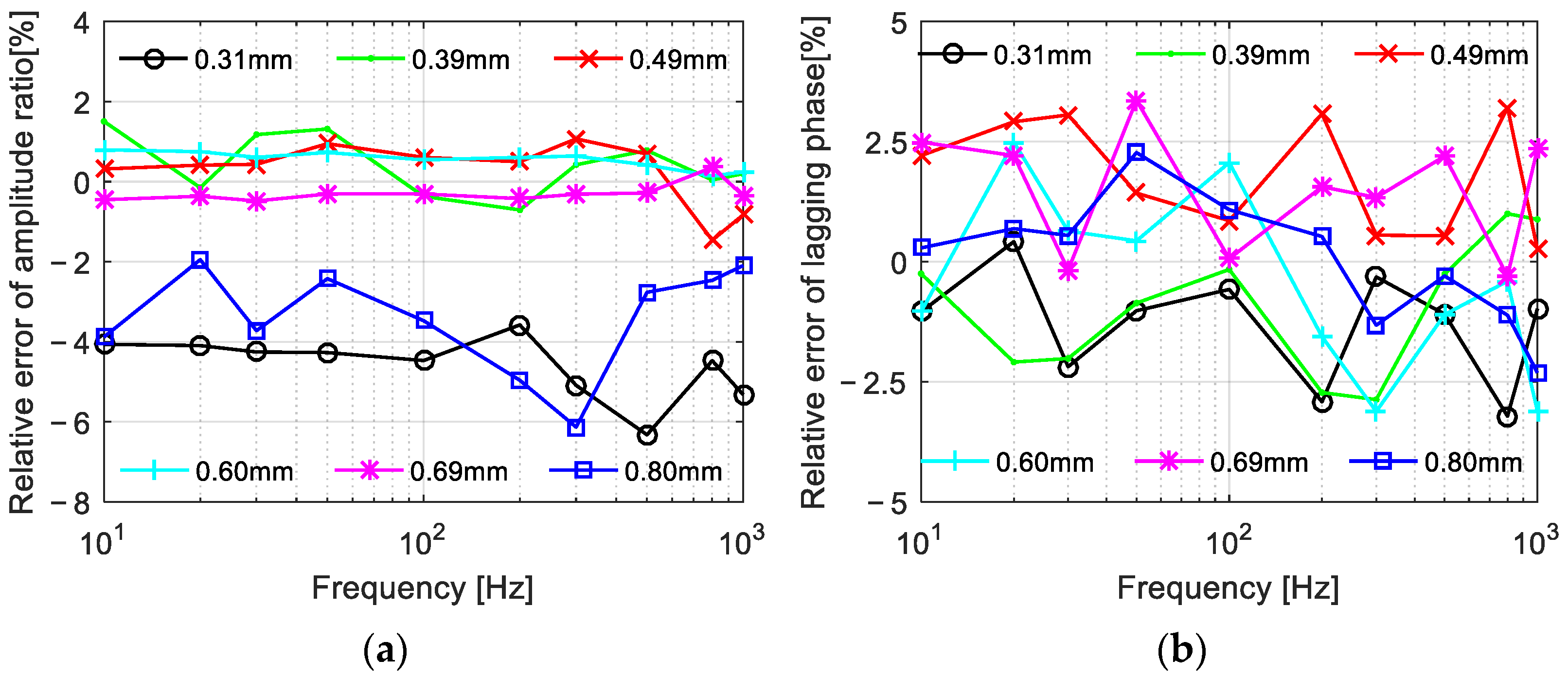
3.2. Sinusoidal Response

Equivalent to the series connection of an inductor and a resistor, the electromagnetic coil was generally modeled as a first-order linear time-invariant system model. Additionally, the amplitude-frequency and phase-frequency characteristics are the most important characteristics of the sinusoidal response of the coil.
Stimulated by a sinusoidal voltage U(t) = Uampsin(ωt), the current response within the coil can be calculated by I(t) = Iampsin(ωtφI), where ω is the angular frequency of the input and φI is the phase lag of the coil current compared to the voltage. From the theory of the linear time-invariant system, the amplitude ratio function is AI = Iamp/Uamp = 1/(R2 + ω2L2)1/2, and tanφI = ωL/R. Substituting Equation (4) into these expressions, one obtains
{ A I = π D c o r e 2 D w i r e 2 C f L a [ 16 ρ L b ( D f + L b ) ] 2 + ( ω C L C f D c o r e 2 D w i r e 2 ) 2 0.806 π D w i r e 4 C f L a [ 16 ρ L b ( D f + L b ) ] 2 + ( 0.806 ω C L C f ) 2 φ I = arctan ω C L C f 16 ρ L b ( D f + L b ) D c o r e 2 D w i r e 2 arctan 0.0504 ω C L C f ρ L b ( D f + L b )
From the empirical equation of the mean magnetic field given in Equation (1), the amplitude radio to inputted voltage of the magnetic field AH and the lagging phase of the magnetic field φH can be easily reached as CHINAI/La and φH = φI. By substituting Equation (5) into these two equations, one obtains
{ A H = 4 C H I L b D c o r e 2 L a [ 16 ρ L b ( D f + L b ) ] 2 + ( ω C L C f D c o r e 2 D w i r e 2 ) 2 3.226 C H I L b D w i r e 2 L a [ 16 ρ L b ( D f + L b ) ] 2 + ( 0.806 ω C L C f ) 2 φ H = arctan ω C L C f 16 ρ L b ( D f + L b ) D c o r e 2 D w i r e 2 arctan 0.0504 ω C L C f ρ L b ( D f + L b )
Changing the frequency from 10 Hz to 1000 Hz, Figure 6 shows the tested and calculated amplitude ratios and phase lags of the magnetic field with respect to the inputted voltage. To demonstrate the influence of the wire diameter more clearly, the wire diameter was plotted on the horizontal axis. From the tested and calculated results, a wider wire diameter is quite helpful for a higher magnetic field amplitude as the amplitude ratio increased faster with an increase in wire diameter. On the contrary, the wire diameter has little influence on the phase lag of the magnetic field, which represents the response time of the magnetic field from 0 to some required proportion of a steady-state value.
Figure 7 shows the relative errors of the model under various frequencies. For predicting the amplitude ratio, the calculation error was lower than 2.0% when the wire diameter was between 0.39 mm and 0.69 mm. The model accuracy was a little lower when the wire diameter was wider than 0.8 mm or narrower than 0.31 mm, as the relative errors at these points were higher than 5%; this was acceptable as the errors were still lower than 6.4%. For computing the lagging phase, the relative errors under different parameters, including various frequencies and wire diameters, were lower than 3.2%, which showed high precision of the model in predicting the lagging phase of the magnetic field. A low calculation accuracy regarding the computing amplitude ratio was mainly caused by poor winding when the coil wire was quite thin or thick. On the whole, the proposed models for the magnetic field amplitude and lagging phase were verified by the low relative errors under most conditions.
Figure 8 shows the relationships between AH and Dwire2. From Figure 8, the linear relationship between the amplitude ratio of the magnetic field and the square of the wire diameter was verified as the tested points under a certain frequency were roughly plotted in a line passing through the origin.

3.3. Square-Wave Response

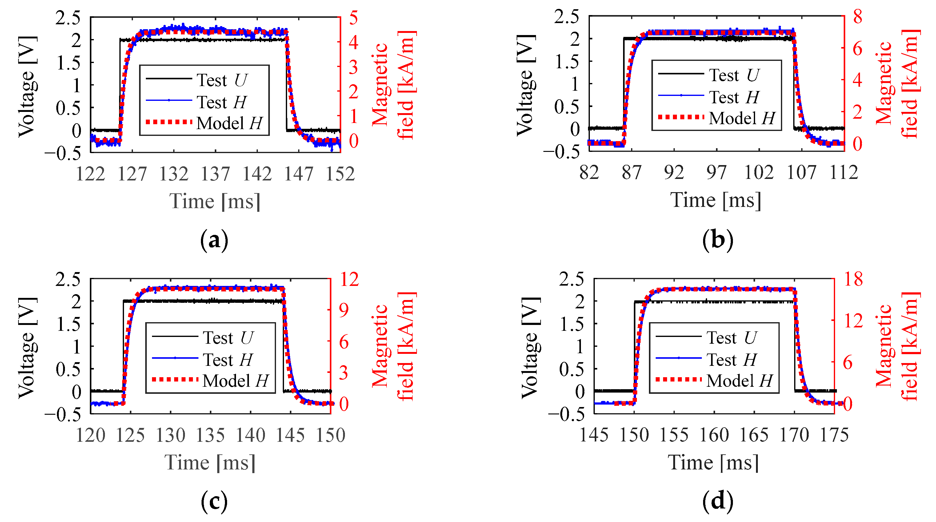
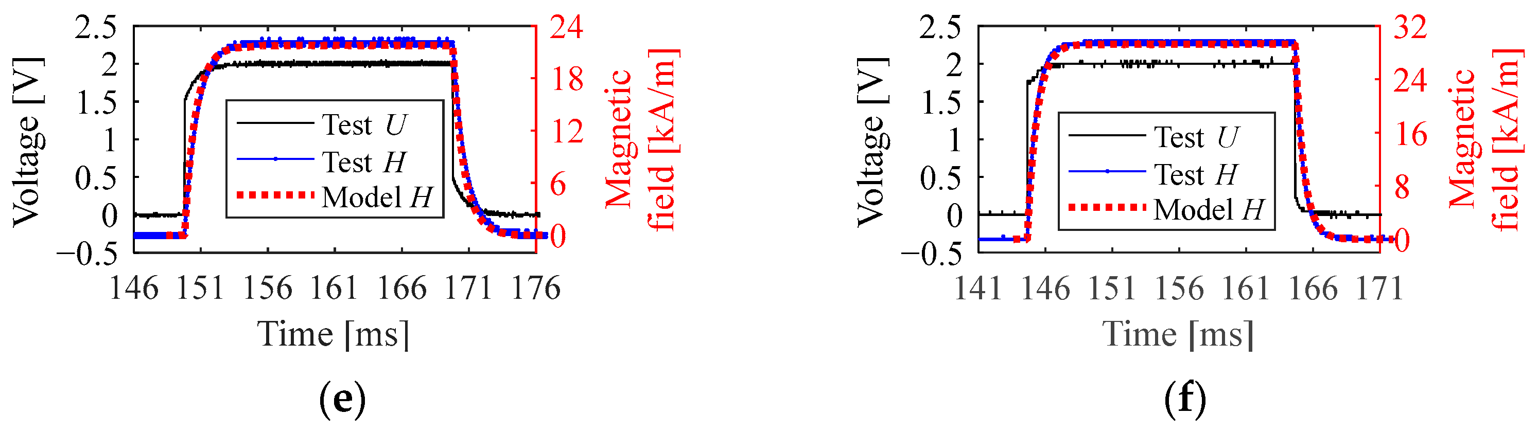
3.3.1. Time-Domain Response

In addition to the sinusoidal voltage, the direct current (DC) square-wave voltage is frequently used, especially to drive an on–off-type actuator.
For the square-wave response, more attention should be paid to the transient-state process. Additionally, based on the first-order linear time-invariant system, the transient-state current within the coil is
I ( t ) = U s t R + ( I 0 U s t R ) e R L t
where I0 is the initial value of the coil current, Ust is the steady-state amplitude of the voltage. Equation (7) was suitable to both the charging and discharging process of the coil. For charging, I0 = 0. For discharging, Ust = 0.
From Equation (4), the reciprocal of the time-constant used in Equation (7) was
R L = ρ ( L f + L b ) D w i r e 2 4 C L 0 C f L a L b D c o r e 2
By substituting Equations (7) and (8) into H(t) = CHINI(t)/La, one obtains the transient-state response of the magnetic field
H ( t ) = C H I C f L b π D w i r e 2 / 4 [ U s t R + ( I 0 U s t R ) e R L t ] = 4 C H I C f L b π D w i r e 2 [ π D c o r e 2 D w i r e 2 U s t 16 ρ C f L a L b ( L f + L b ) + ( I 0 π D c o r e 2 D w i r e 2 U s t 16 ρ C f L a L b ( L f + L b ) ) e ρ ( L f + L b ) D w i r e 2 4 C L 0 C f L a L b D c o r e 2 t ] = C H I D c o r e 2 4 ρ L a ( L f + L b ) U s t + 4 C H I C f L b π D w i r e 2 I 0 e ρ ( L f + L b ) D w i r e 2 4 C L 0 C f L a L b D c o r e 2 t C H I D c o r e 2 4 ρ L a ( L f + L b ) U s t e ρ ( L f + L b ) D w i r e 2 4 C L 0 C f L a L b D c o r e 2 t
The inputted voltage was generated with an amplitude of 2 V and a high-voltage duration of 20 ms to guarantee the coil current reaching the steady state. The time-domain magnetic fields are shown in Figure 9. From the test and model, the proposed model precisely calculated the amplitudes and effectively described the curve shapes under different wire diameters as the transient-state results were also quite close.

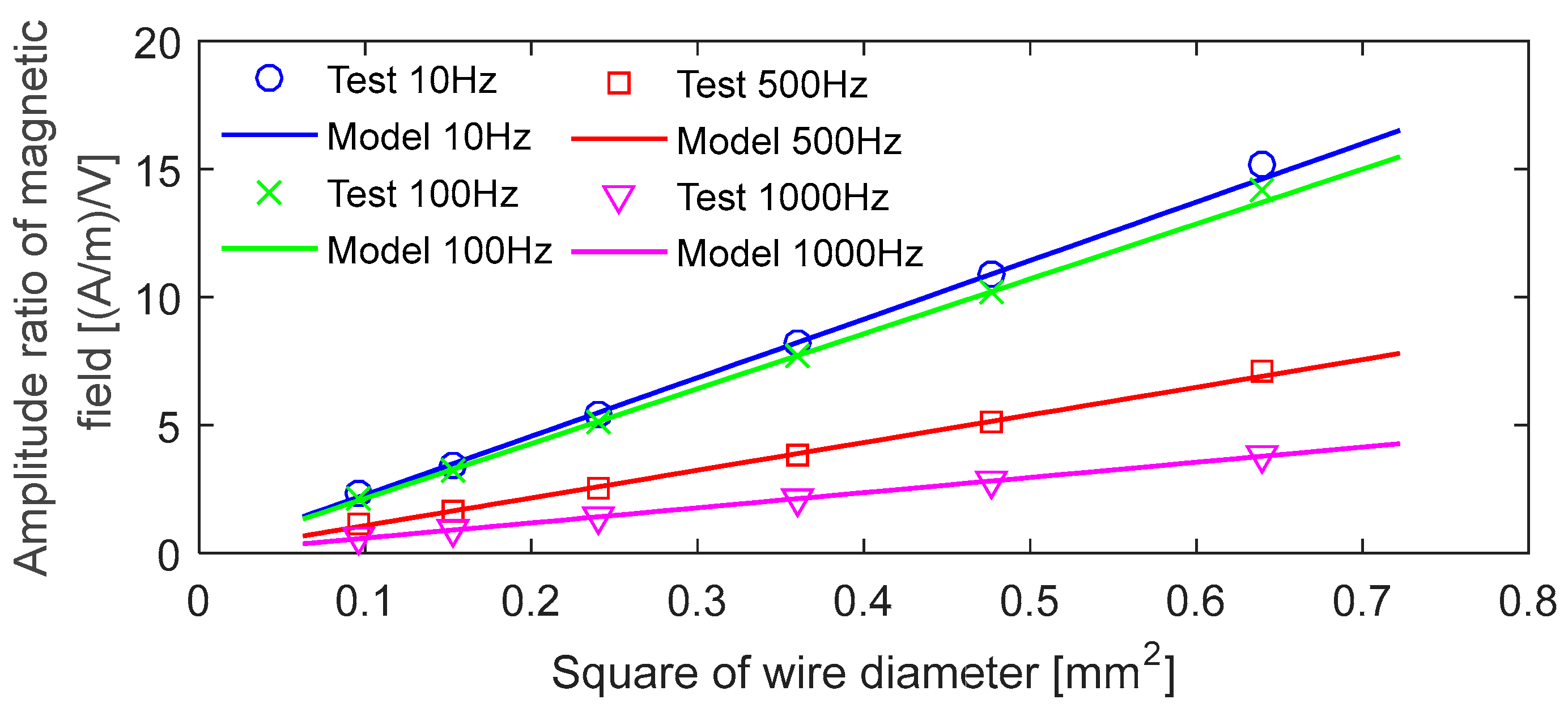
3.3.2. Steady-State Value and Response Time

The steady-state value and response time are the most important characteristic parameters of the on–off-type actuator. When the square-wave voltage maintains a high level for a long enough duration, the steady-state response of the magnetic field Hst can be easily acquired from Equation (9), as
H s t = C H I D c o r e 2 4 ρ L a ( L f + L b ) U s t 0.2016 C H I D w i r e 2 ρ L a ( L f + L b ) U s t
By exacting the mean value of the magnetic field in the steady-state stage, Figure 10 shows the curves of Hst vs. Dwire from the test and model. From the tested and calculated results, a higher Dwire is helpful for a higher Hst. More specifically, Hst was positively proportional to Dwire2, as explained in Equation (10). Thus, the change law of the Hst under the square wave was the same as one of the magnetic field amplitudes under the sinusoidal voltage. It was easily illustrated that both the functions of 1/(R2 + ω2L2)1/2 and 1/R can be expressed by the quartic function vs. the wire diameter approximately. In addition, the relatively errors under different wire diameters were less than 1.2% thus, the model can predict the steady-state magnetic field quite effectively.
There are two commonly used response times—the time from 0 to the required intensity and the time from 0 to the required proportion of the steady-state value. The former was especially concerned when the high-opening voltage was employed and the latter was generally concerned when the standard square-wave voltage was employed (or the duty cycle was adjusted but not the amplitude in the voltage wave).
By imposing Ireq the required intensity of the coil current and substituting Ireq into Equation (7), the response time tIv can be reached, as
t I v = L R ln ( 1 + I r e q U s t / R I r e q ) = C L C f 16 ρ L b ( D f + L b ) D c o r e 2 D w i r e 2 ln ( 1 + I r e q π D c o r e 2 D w i r e 2 U s t / [ 16 ρ C f L a L b ( D f + L b ) ] I r e q )
Similarly, by substituting the required magnetic field Hreq into Equation (9), one obtains the response time to the specified magnetic field intensity tHv, as
t H v = L R ln ( 1 + L a H r e q C H I N U s t / R L a H r e q ) = C L C f 16 ρ L b ( D f + L b ) D c o r e 2 D w i r e 2 ln ( 1 + L a H r e q C H I D c o r e 2 U s t / [ 4 ρ ( D f + L b ) ] L a H r e q ) 0.0504 ω C L C f ρ L b ( D f + L b ) ln ( 1 + L a H r e q 0.2016 C H I D w i r e 2 U s t / [ ρ ( D f + L b ) ] L a H r e q )
From the calculated result, it can be observed that a thicker wire is better for reducing both the response time of the coil current and one of the magnetic fields, while the change degree is different. The enameled wire diameter has more influence on the response time of the coil current than that of the magnetic field as tIv is in the function form of aln [1 + b/(cx2b)] vs. Dwire while tHv is expressed by aln [1 + b/(cx4b)] vs. Dwire.
The response time to a specified proportion of the steady-state value can be easily deduced from Equations (10) and (12). For a given proportion p, the corresponding intensities of the coil current and magnetic field are, respectively, Ireq = p(Ust/R) or Hreq = p[CHIN(Ust/R)/La]. By substituting the two expressions into Equations (10) and (11), one obtains the response time to a specified proportion, as
t H p = t I p = L R ln ( 1 1 p ) = C L C f 16 ρ L b ( D f + L b ) D c o r e 2 D w i r e 2 ln ( 1 1 p ) 0.0504 ω C L C f ρ L b ( D f + L b ) ln ( 1 1 p )
where p is a constant belonging to (0, 1).
Compared to tHv, the factors influencing tHp were almost independent of Dwire. More specifically, tHp was just determined by the ratio of L/R. The value of L/R was only slightly influenced by Dwire; optimizing the wire diameter would be helpless to promote this type of response speed.
Figure 11 shows the two types of response times from the tested and calculated results; the specified intensities Hreq were 3 kA/m, 3.5 kA/m, and 4 kA/m, and the specified proportions p were 0.7, 0.8, and 0.9. Just as predicted by the model, Hreq was effectively reduced by increasing Dwire. Furthermore, Hreq declined fast first and then slowly with Dwire increasing. For the value of tHp, it changed slightly with Dwire increasing. The model was verified as the calculated results were consistent with the experimental data.
On the whole, increasing the wire diameter is quite helpful for reducing the response time from 0 to a specified value of the coil current or magnetic field, while failing to improve the response speed from 0 to the steady-state or any other proportional value. Therefore, for an electromagnetic actuator stimulated by a high-open-low-hold-type voltage, a coil with a wider wire diameter will be stimulated more quickly to save the response time of the whole actuator, while when a traditional square-wave voltage is introduced, an adjustment in the wire diameter is helpless.

4. Conclusions

An analytical model of the mean magnetic field for the hollow cylindrical coil used in a magnetically driven actuator was proposed in this paper. Additionally, the selection of the enameled wire diameter was optimized for a high-amplitude and fast-response magnetic field based on the model.
(1)
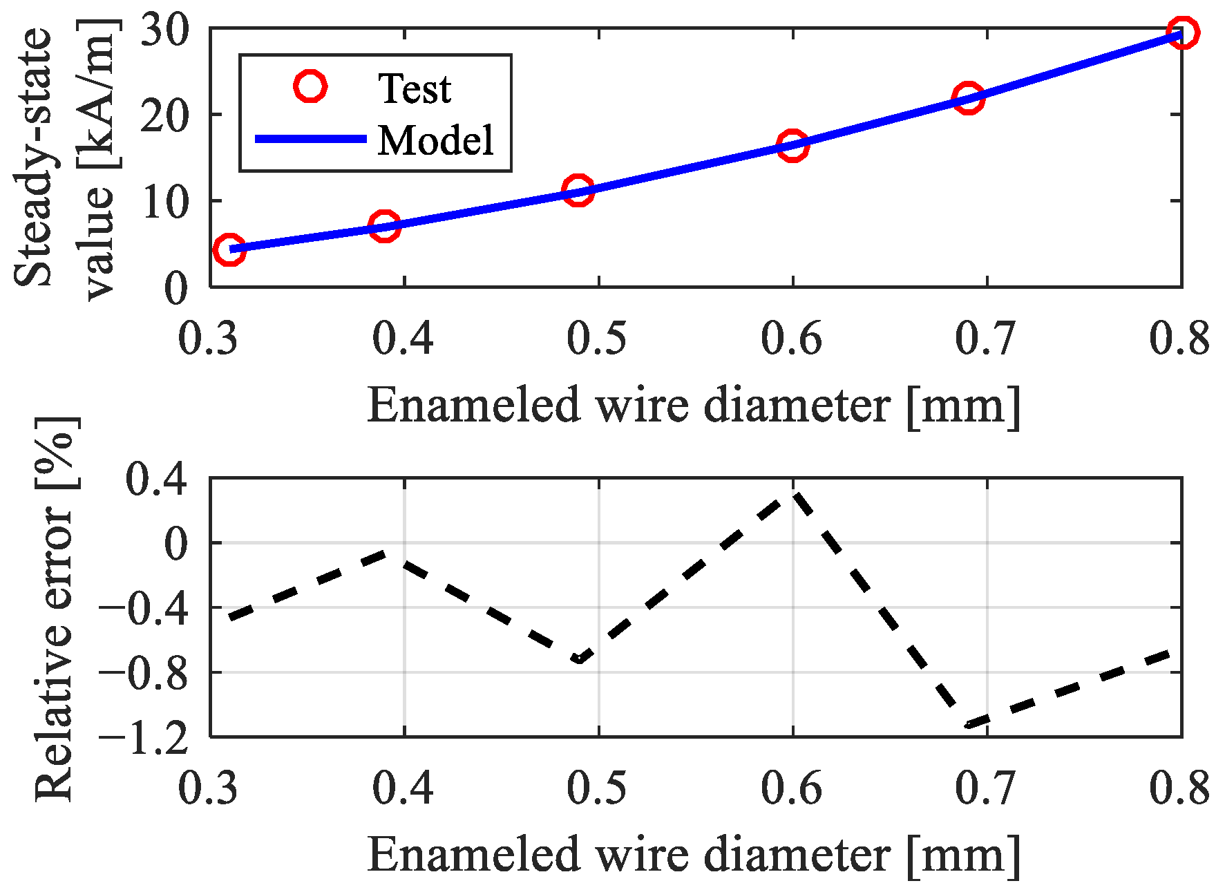
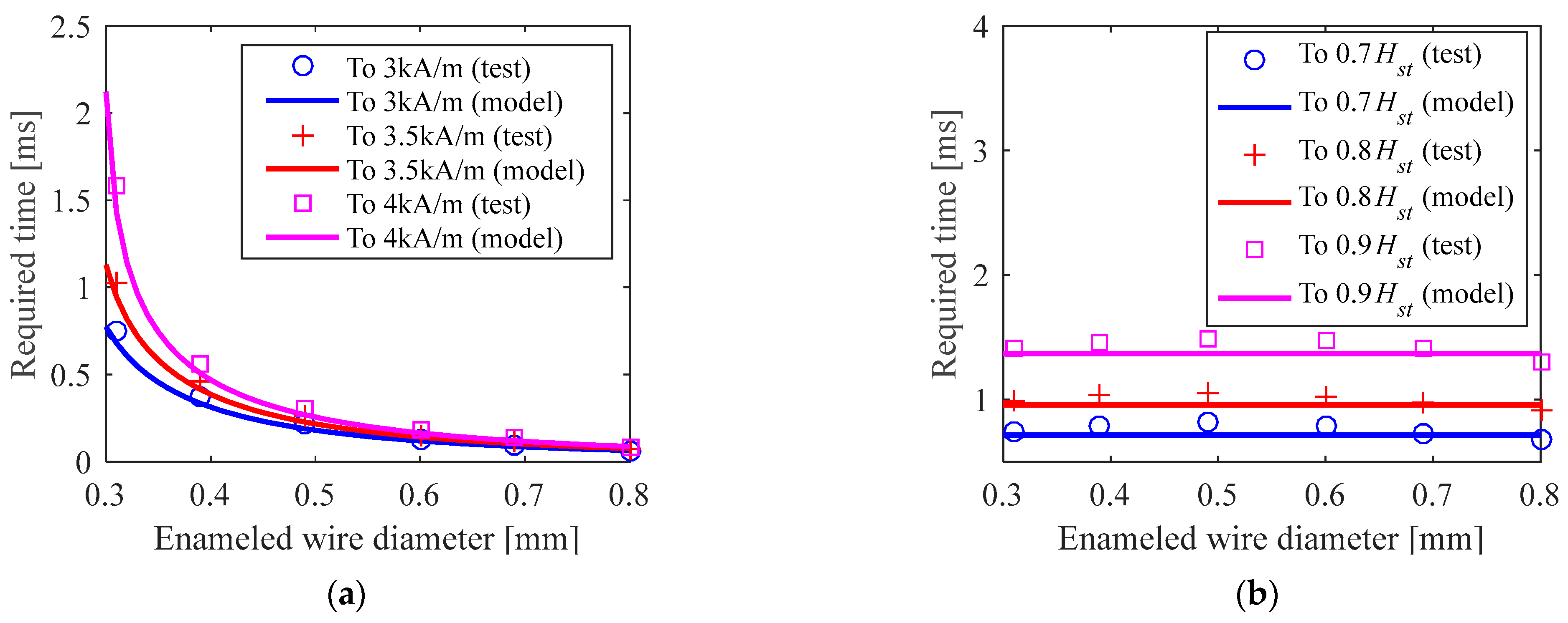
The resistance and inductance are inversely proportional functions vs. the quartic of the enameled wire diameter. Under the sinusoidal voltage, a wider wire diameter is quite helpful for a higher magnetic field amplitude while it has little influence on the phase lag of the magnetic field. Under the square-wave voltage, the steady-state magnetic field was positively proportional to the square of the wire diameter, as a wider wire diameter is helpful for a higher steady-state magnetic field. Regarding the response speed, increasing the wire’s diameter is helpful for reducing the response time from 0 to the specified intensity, while it is helpless to improve the response speed from 0 to the steady-state or any other proportional value.
(2)
The proposed model was verified as the calculated results from the model were in good agreement with the experimental results. Specifically, the relative errors of the model in computing the resistance and the inductance were lower than 3.1% and 2.8%, respectively. For predicting the sinusoidal response, the errors were lower than 6.4% (lower than 2.0% under most conditions) in computing the amplitude and lower than 3.2% in computing the lagging phase. For predicting the square-wave response, the model calculated the amplitudes with errors lower than 1.2% and described the curve shape effectively.
This paper was devoted to the promotion of the output performance of the whole magnetically driven actuator without considering the coil quality factor or power loss. Further work can focus on reducing the power loss of the coil.

Author Contributions

Conceptualization. G.X.; Data curation, Z.W.; Formal analysis, Z.W.; Investigation: Z.W.; Software and visualization, Z.W. and G.X.; Methodology, G.X.; Validation, G.X. and H.B.; Funding acquisition, H.B. and G.X.; Writing—review and editing, Z.W. and G.X.; Writing—review and editing, H.B., G.X. and Z.R.; Supervision: Z.R. All authors have read and agreed to the published version of the manuscript.

Funding

This work was supported by the Young and Middle-aged Teachers Education and Research Project (Science and Technology) of Fujian Province (No. JAT220016) and First Batch of Yin Ling Fund (No. ZL3H39).

Data Availability Statement

The data presented in this study are available on request from the corresponding author.

Acknowledgments

The authors thank Zhaoshu Yang (in China Astronaut Research and Training Center) and Tuo Li (in Officers College of PAP) for their improvement in the English of this article.

Conflicts of Interest

The authors declare no conflict of interest.

References

  1. Zhao, T.; Yuan, H.; Pan, H.; Li, B. Study on the rare-earth giant magnetostrictive actuator based on experimental and theoretical analysis. J. Magn. Magn. Mater. 2018, 460, 509–524. [Google Scholar] [CrossRef]
  2. Xue, G.; Zhang, P.; Li, X.; He, Z.; Wang, H.; Li, Y.; Ce, R.; Zeng, W.; Li, B. A review of giant magnetostrictive injector (GMI). Sensor. Actuat. A-Phys. 2018, 273, 159–181. [Google Scholar] [CrossRef]
  3. Braghin, F.; Cinquemani, S.; Resta, F. A model of magnetostrictive actuators for active vibration control. Sensor. Actuat. A-Phys. 2011, 165, 342–350. [Google Scholar] [CrossRef]
  4. Sobczyk, M.; Wiesenhütter, S.; Noennig, J.R.; Wallmersperger, T. Smart materials in architecture for actuator and sensor applications: A review. J. Intell. Mater. Syst. Struct. 2022, 33, 379–399. [Google Scholar] [CrossRef]
  5. Zhang, X.; Zhang, Y.; Guo, Y.; Li, L. Engineering Vibration Control Based on Rotating Actuator. J. Nanjing Univ. Aeronaut. Astronaut. 2018, 50, 601–610. [Google Scholar]
  6. McIvor, B.; Chahl, J. Energy Efficiency of Linear Electromagnetic Actuators for Flapping Wing Micro Aerial Vehicles. Energies 2020, 13, 1075. [Google Scholar] [CrossRef] [Green Version]
  7. Li, Y.; Wu, J.; Hu, J.; Wang, Q.; Liu, C. Analysis of Factors Influencing Peak Torques and Peak Losses of Rotary Voice Coil Actuators Used in Aerospace. IEEE Access 2021, 9, 57120–57126. [Google Scholar]
  8. Li, W.; Shi, G.; Asme. Review of Aerospace Actuator Technology. In Proceedings of the 33rd Bath/ASME International Symposium on Fluid Power and Motion Control (FPMC), Electr Network, Longboat Key, FL, USA, 9–11 September 2020. [Google Scholar]
  9. Kang, J.G.; Kwon, J.Y.; Lee, M.S. A Dynamic Power Consumption Estimation Method of Electro-mechanical Actuator for UAV Modeling and Simulation. Int. J. Aeronaut. Space Sci. 2022, 23, 233–239. [Google Scholar] [CrossRef]
  10. Ashpis, D.E.; Thurman, D.R. Dielectric Barrier Discharge (DBD) Plasma Actuators for Flow Control in Turbine Engines: Simulation of Flight Conditions in the Laboratory by Density Matching. Int. J. Turbo Jet-Engines 2019, 36, 157–173. [Google Scholar] [CrossRef]
  11. Roussel, J.; Budinger, M.; Ruet, L. Preliminary Sizing of the Electrical Motor and Housing of Electromechanical Actuators Applied on the Primary Flight Control System of Unmanned Helicopters. Aerospace 2022, 9, 473. [Google Scholar] [CrossRef]
  12. Misra, R.; Wisniewski, R.; Zuyev, A. Attitude Stabilization of a Satellite Having Only Electromagnetic Actuation Using Oscillating Controls. Aerospace 2022, 9, 444. [Google Scholar] [CrossRef]
  13. Yang, X.; Zhu, Y.; Ji, L.; Fei, S.; Guo, Y. Experimental investigation and characteristic analysis of a giant magnetostrictive materials-based electro-hydrostatic actuator. AcAAS 2016, 37, 2839–2850. [Google Scholar]
  14. Yang, X.; Zhu, Y.; Fei, S.; Ji, L.; Guo, Y. Magnetic field analysis and optimization of giant magnetostrictive electro-hydrostatic actuator. JAerP 2016, 31, 2210–2217. [Google Scholar]
  15. Fang, S. Research on Robotic Motion Planning and Compliance Control for Ultrasonic Strengthening of Aviation Blade Surface; Beijing Jiaotong University: Beijing, China, 2021. [Google Scholar]
  16. Grunwald, A.; Olabi, A.G. Design of a magnetostrictive (MS) actuator. Sensor. Actuat. A-Phys. 2008, 144, 161–175. [Google Scholar] [CrossRef] [Green Version]
  17. Shi, X.; Ren, C.; Li, Y.; Ding, G. Design, Modeling, and Optimization of a Bistable Electromagnetic Actuator with Large Deflection. IEEE Magn. Lett. 2021, 12, 2102505. [Google Scholar] [CrossRef]
  18. Lu, Y.W.; Yang, Y.; Zhang, M.; Wang, R.M.; Zhu, B.L.; Jiang, L. Magnetic Enhancement-Based Multi-Objective Optimization Design of the Large-Scale High-Intensity Homogeneous Magnetic Field Coil System. IEEE Trans. Magn. 2022, 58, 9. [Google Scholar] [CrossRef]
  19. Yan, H.; Gao, H.; Hao, H.; Zhang, Z.; Zhuang, F. Design and Simulation of Exciting Coil in Rare Earth Giant Magnetostrictive Actuator. Mech. Sci. Technol. Aerosp. Eng. 2019, 38, 1569–1575. [Google Scholar]
  20. Yan, L.; Wu, Z.; Jiao, Z.; Chen, C.-Y.; Chen, I.M. Equivalent energized coil model for magnetic field of permanent-magnet spherical actuators. Sensor. Actuat. A-Phys. 2015, 229, 68–76. [Google Scholar] [CrossRef]
  21. Kim, H.; Kim, H.; Gweon, D. Magnetic field analysis of a VCM spherical actuator. Sensor. Actuat. A-Phys. 2013, 195, 38–49. [Google Scholar] [CrossRef]
  22. Olabi, A.G.; Grunwald, A. Computation of magnetic field in an actuator. Simul. Model. Pract. Theory 2008, 16, 1728–1736. [Google Scholar] [CrossRef] [Green Version]
  23. Geng, H.; Zhang, X.; Yan, S.; Tong, L.; Ma, Q.; Xu, M.; Zhang, Y.; Han, Y. Magnetic field analysis and performance optimization of hybrid excitation generators for vehicles. Sustain. Energy Technol. Assess. 2022, 52, 102200. [Google Scholar] [CrossRef]
  24. Lee, J.; Dede, E.M.; Banerjee, D.; Iizuka, H. Magnetic force enhancement in a linear actuator by air-gap magnetic field distribution optimization and design. Finite Elem. Anal. Des. 2012, 58, 44–52. [Google Scholar] [CrossRef]
  25. Yang, X.; Zhu, Y.; Zhu, Y. Characteristic investigations on magnetic field and fluid field of a giant magnetostrictive material-based electro-hydrostatic actuator. Proc. Inst. Mech. Eng. Part G J. Aerosp. Eng. 2018, 232, 847–860. [Google Scholar] [CrossRef]
  26. Golda, D.; Culpepper, M.L. Modeling 3D magnetic fields for precision magnetic actuators that use non-periodic magnet arrays. Precis. Eng. 2008, 32, 134–142. [Google Scholar] [CrossRef]
  27. Chen, Z.; Yang, X.; Li, S.; Zhang, Z.; Chen, Y. Dynamic modeling of stack giant magnetostrictive actuator with magnetic equivalent network considering eddy current effect. J. Appl. Phys. 2022, 131, 224503. [Google Scholar] [CrossRef]
  28. Chen, L.; Zhu, Y.; Ling, J.; Zhang, M. Development and Characteristic Investigation of a Multidimensional Discrete Magnetostrictive Actuator. IEEE-ASME T. Mech. 2022, 27, 2071–2079. [Google Scholar] [CrossRef]
  29. Ramirez-Laboreo, E.; Roes, M.G.L.; Sagues, C. Hybrid Dynamical Model for Reluctance Actuators Including Saturation, Hysteresis, and Eddy Currents. IEEE-ASME T. Mech. 2019, 24, 1396–1406. [Google Scholar] [CrossRef]
  30. Lyu, Z.; Zhang, J.; Wang, S.; Zhao, X.; Li, T. Optimal design of multi-coil system for generating uniform magnetic field based on intelligent optimization algorithm and finite element method. J. Beijing Univ. Aeronaut. 2019, 45, 980–988. [Google Scholar]
  31. Sun, J.; Ren, J.; Le, Y.; Wang, H. Analysis of Air-Gap Magnetic Field and Structure Optimization Design of Hollow-Cup Motor. Aerospace 2022, 9, 549. [Google Scholar] [CrossRef]
  32. Niu, M.; Yang, B.; Yang, Y.; Meng, G. Modelling and parameter design of a 3-DOF compliant platform driven by magnetostrictive actuators. Precis. Eng. 2020, 66, 255–268. [Google Scholar] [CrossRef]
  33. Zhou, J.; He, Z.; Shi, Z.; Song, J.; Li, Q. Design and experimental performance of an inertial giant magnetostrictive linear actuator. Sensor. Actuat. A-Phys. 2020, 301, 111771. [Google Scholar] [CrossRef]
  34. Liu, H.; Jia, Z.; Wang, F.; Zong, F. Research on the constant output force control system for giant magnetostrictive actuator disturbed by external force. Mechatronics 2012, 22, 911–922. [Google Scholar] [CrossRef]
  35. Xue, G.; Zhang, P.; He, Z.; Li, D.; Yang, Z.; Zhao, Z. Displacement model and driving voltage optimization for a giant magnetostrictive actuator used on a high-pressure common-rail injector. Mater. Des. 2016, 95, 501–509. [Google Scholar] [CrossRef]
  36. Bright, C.B.; Garza, J.C. Possible Very High Speed Rate Shaping Fuel Injector; SAE Technical Paper 2007-01-4113; SAE: Warrendale, PA, USA, 2007. [Google Scholar]
  37. Xue, G.; Zhang, P.; He, Z.; Li, D.; Huang, Y.; Xie, W. Design and experimental study of a novel giant magnetostrictive actuator. J. Magn. Magn. Mater. 2016, 420, 185–191. [Google Scholar] [CrossRef]
  38. Xue, G.; Ge, J.; Ning, P.; Zhou, J.; Wang, K.; Cheng, Z.; Pei, G. Simulation studies on the boot shape injection of a giant magnetostrictive injector. Sci. Rep. 2021, 11, 22999. [Google Scholar] [CrossRef]
  39. Hoang, M.C.; Kim, J.; Park, J.-O.; Kim, C.-S. Optimized magnetic field control of an electromagnetic actuation system for enhanced microrobot manipulation. Mechatronics 2022, 85, 102830. [Google Scholar] [CrossRef]
  40. Pang, H.Y.; Duan, L.H.; Quan, W.; Wang, J.; Wu, W.F.; Fan, W.F.; Liu, F. Design of Highly Uniform Three Dimensional Spherical Magnetic Field Coils for Atomic Sensors. IEEE Sens. J. 2020, 20, 11229–11236. [Google Scholar] [CrossRef]
  41. Tang, Y.D.; Jin, T.; Flesch, R.C.C.; Gao, Y.M. Improvement of solenoid magnetic field and its influence on therapeutic effect during magnetic hyperthermia. J. Phys. D-Appl. Phys. 2020, 53, 6. [Google Scholar] [CrossRef]
  42. Rong, C.; He, Z.B.; Xue, G.M.; Zhou, J.T.; Zhao, Z.L. Physics-based modeling and multi-objective parameter optimization of excitation coil for giant magnetostrictive actuator used on fuel injector. Meas. Control 2022, 55, 421–436. [Google Scholar] [CrossRef]
  43. Fang, S.; Chen, Y.; Yang, Y. Optimization design and energy-saving control strategy of high power dc contactor. Int. J. Electr. Power Energy Syst. 2020, 117, 105633. [Google Scholar] [CrossRef]
  44. Bright, C.B.; Faidley, L.; Witthauer, A.; Rickels, E.; Donlin, T. Programmable Diesel Injector Transducer Test Results; SAE Technical Paper 2011-01-0381; SAE: Warrendale, PA, USA, 2011. [Google Scholar]
Figure 2. Experimental system and wound coils: (a) block diagram of the experimental system; (b) dimensioned sectional drawing of the coil, (c) photograph of the experimental system; (d) photograph of the coils.
Aerospace 10 00270 g002
Figure 3. Actual and fitted values of Dcore simultaneously supplied the relative errors of the fitting lines with and without an intercept.
Aerospace 10 00270 g003
Figure 4. Relative errors of the positively proportional function of the available area of coil skeleton vs. the cross-sectional area of enameled wire.
Aerospace 10 00270 g004
Figure 5. Curves of the static resistance and static inductance vs. the enameled wire diameter.
Aerospace 10 00270 g005
Figure 6. Amplitude ratio and phase lag of the magnetic field under different wire diameters: (a) curves of the amplitude ratio vs. enameled wire diameter; (b) curves of the phase lag vs. enameled wire diameter.
Aerospace 10 00270 g006
Figure 7. The relative errors of the model in computing the coil current under a harmonic voltage: (a) the relative errors of computing the amplitude ratio; (b) the relative errors of computing the phase lag.
Aerospace 10 00270 g007
Figure 8. Linear curves of AH-Dwire2 from the model and test under different frequencies.
Aerospace 10 00270 g008
Figure 9. The dynamic magnetic field under square-wave input: (a) Dwire = 0.31 mm; (b) Dwire = 0.39 mm; (c) Dwire = 0.49 mm; (d) Dwire = 0.60 mm; (e) Dwire = 0.69 mm; (f) Dwire = 0.80 mm.
Aerospace 10 00270 g009aAerospace 10 00270 g009b
Figure 10. Steady-state magnetic field of the square-wave response from the test and model.
Aerospace 10 00270 g010
Figure 11. The response time of the square-wave response from the test and model: (a) the time from 0 to specified intensities, respectively, of 3 kA/m, 3.5 kA/m, and 4 kA/m; (b) the time from 0 to the specified proportions of the steady-state response, respectively, of 0.7, 0.8, and 0.9.
Aerospace 10 00270 g011
Table 1. The main parameters of the coils.
Coil LabelExternal Diameter
(Dwire) [mm]
Core Diameter
(Dwire) [mm]
Number of Coil Turns
(N) [Null]
Resistance
(R) [Ω]
Inductance
(L) [mH]
Coil 10.310.2783718.32510.933
Coil 20.390.355377.4724.487
Coil 30.490.443422.9941.789
Coil 40.600.552291.3420.801
Coil 50.690.641750.7670.459
Coil 60.800.741240.4100.243
Table 2. The main parameters of the skeleton and material.
Parameter (Variable) [Unit]Value
Coil length (La) [mm]16.5
Coil thickness (Lb) [mm]6.8
Diameter of skeleton shaft (Lf) [mm]18.2
Resistivity of copper (ρ) [Ω·m]1.71 × 10⁻⁸
Proportional coefficient (CHI) [null]0.8
Table 3. Linear fitting between Dcore and Dwire when Dwire ∈ [0.3, 0.8].
DwireTested DcoreDcore from
0.962 Dwire − 0.0277
Relative Error of
0.962 Dwire − 0.0277 (%)
Dcore from
0.898 Dwire
Relative Error of
0.898 Dwire (%)
0.310.270.27050.19260.27843.1037
0.390.350.3475−0.72000.35020.0629
0.490.440.44370.83640.44000.0045
0.60.550.5495−0.09090.5388−2.0364
0.690.640.6361−0.61250.6196−3.1844
0.80.740.74190.25680.7184−2.9189
Table 4. Coil turns from the test and model.
Coil LabelCoil Turns from TestCoil Turns from Model 1Relative Error (%)
1837847.331.23
2537535.36−0.30
3342339.15−0.83
4229226.19−1.23
5175171.03−2.27
6124127.232.61
1 Cannot be an integer.
Disclaimer/Publisher’s Note: The statements, opinions and data contained in all publications are solely those of the individual author(s) and contributor(s) and not of MDPI and/or the editor(s). MDPI and/or the editor(s) disclaim responsibility for any injury to people or property resulting from any ideas, methods, instructions or products referred to in the content.

