Article

Effects of Inlet Swirl Distortion on a Multi-Stage Compressor with Inlet Guide Vanes and Stall Margin Enhancement Method

1
School of Energy and Power Engineering, Beihang University, Beijing 100191, China
2
Beihang Hangzhou Innovation Institute, Hangzhou 310023, China
3
Research Institute of Aeroengine, Beihang University, Beijing 100191, China
*
Author to whom correspondence should be addressed.
Aerospace 2023, 10(2), 141; https://doi.org/10.3390/aerospace10020141
Submission received: 7 December 2022 / Revised: 29 January 2023 / Accepted: 30 January 2023 / Published: 2 February 2023
(This article belongs to the Section Aeronautics)

Abstract

:
Inlet swirl distortion is generally considered as a type of velocity distortion, and inlet guide vanes (IGVs) are widely used in the multi-stage compressor of aero-engines to eliminate the tangential velocity of the swirl flow. However, few studies have explored whether there still exists some negative influence of inlet swirl distortion on the compressor, even after the installation of IGVs. Therefore, in this study, the influence of various types of inlet swirl distortions on a multi-stage compressor with the installation of IGVs is investigated. A swirl distortion generator installed in the inlet duct was designed to produce various types of swirl flow patterns. When the distortion intensity increased to some degree, there still existed a decrease in the compressive capability and an obvious additional efficiency loss. The inlet twin swirl distortion was accompanied by total pressure distortion, so even with the installation of IGVs, there was still a significantly negative influence on the performance of the multi-stage compressor, especially the stall margin. Subsequently, to improve the stall margin under inlet swirl distortion, the stall precursor-suppressed (SPS) casing treatment was installed in the first stage of the multi-stage compressor. It could enhance the stall margin of the compressor with no obvious change in the characteristic curves and no additional efficiency loss under various types of inlet swirl distortions, and its mechanism was verified by capturing the dynamic pressure characteristics.

1. Introduction

Aero-engines encounter various inlet distortions that may be induced by the installation devices, specific air maneuvers, or a change in the operating environment [1,2]. Under the condition of inlet distortions, instability phenomena, rotating stall, or surge, which cause much potential catastrophic damage to the whole system, may occur in advance [3], inducing a sharp decrease in the stall margin of the compressor. Therefore, it is crucial to assess the influence of inlet distortion on the stall margin and develop corresponding methods for extending the operating range of the compressor.
For the majority of modern fighter jets, the engines are installed inside the fuselage to cover the infrared thermal radiation [4], so the inlet duct is generally designed to be S-shaped, named S-ducts. Due to the two bends in S-ducts, they tend to produce swirl flow at the outlet of the ducts, which was first found to be the primary contributor to the instability problem in the twin-engine Tornado fighter–bomber [5]. In addition, there also exists swirl flow caused by the application of embedded auxiliary power unit (APU) installations or the plenums installed in the turbine engine for marine and industrial power [6]. This phenomenon was previously referred to as inlet swirl distortion. To capture the spatial characteristics of swirl flow caused by an S-duct at the inlet of a compressor, some studies [7,8] based on numerical calculations and experiments were conducted to explore the swirl flow in S-ducts and distinctly showed its evolution process and the flow pattern. There are also some other types of S-ducts, such as inter-spool ducts [9,10], which can cause inlet distortion to the downstream components.
The S-16 committee of the Society of Automotive Engineers (SAE) produced a detailed and systematic description of the characterization of swirl flow by defining a series of swirl descriptors to perform a quantitative evaluation [11]. Swirl flow can be grouped into four fundamental categories strictly based on the flow pattern. The main types encountered in aero-engines with S-ducts installed are bulk swirl and paired swirl [11]. The former is accompanied by the entire flow field rotating in one direction with respect to the rotational axis of the compressor, and can be divided into co-rotating and counter-rotating bulk swirl according to the flow rotation direction relative to the compressor’s rotation. The latter is accompanied by several vortices rotating in opposite directions. Due to the symmetric structure of S-ducts, the two vortices generally have equal magnitudes and opposite rotations, termed twin-paired swirl.
Swirl flow induced by an S-duct will influence the performance and stability of the downstream compressor. Pazur et al. [12] used a delta wing to generate a pair of vortices for simulating inlet swirl and investigated the influence of swirl distortions on the performance of an axial compressor. Schmid et al. [13] researched the influences of co- and counter-rotating swirl distortion and discovered that the two kinds of swirl distortion had different effects on compressor performance, but did not negatively influence the stall margin of the low-pressure compressor. Rademakers et al. [14] conducted an experiment on a Larzac 04 jet engine to explore the influence of S-duct inlets on the performance and stability of the compressor. In their experiment, distortion generators were designed to reproduce the flow configurations of swirl distortion, and the unsteady flow phenomena in the compressor were detected. Dong et al. [15] carried out an experiment on inlet swirl distortion and discovered that counter-rotating bulk swirl would improve the pressure ratio, but exert a negative influence on the efficiency and stall margin of the compressor; under the condition of twin swirl distortion, the performance and stability of the compressor decreased. On the other hand, numerical calculations were performed to investigate the influence of swirl distortion. Yogi et al. conducted a series of constitutive studies about inlet swirl distortion by numerical calculation, from the design of a distortion generator [16] to the simulation of compressor performance [17], and reached a similar conclusion. The steady numerical calculations generally employed the frozen rotor approach to treat the interface of the rotor and stator. However, this treatment could not consider the rotor/stator interaction and may have impeded the downstream propagation of distortion perturbations. For inlet swirl distortion, especially twin swirl, there exists intensive nonuniform velocity and pressure in the circumferential direction [15], so whether the calculation based on the frozen rotor approach is applicable is worth discussing. The author merely tested the results under the uniform inlet condition on a one-stage compressor, which also raises our doubts. Therefore, due to the three-dimensional and nonuniform flow characteristics of inlet swirl distortion, unsteady calculation based on the whole annular is necessary, especially for multi-stage compressors, but its huge computational cost may be unacceptable in applications. In addition, due to the complex flow, some analytical models [18,19] may be also inappropriate for the research of swirl distortion. These experiments might still occupy an important role in research on the influence of inlet swirl distortion on the multi-stage compressor.
Furthermore, in fighter engines, which require high performance with a constant mass rate, the structure design of a high hub ratio is adopted, but they are more sensitive to changes in the angle of incidence. It was discovered that, due to the installation of IGVs, all modern American military high-performance engines, such as the F-14, and F-15, seem to be less sensitive to inlet swirl flow [5]. Therefore, it was concluded that IGVs can remove the swirl component prior to the flow entering the rotor, and they have been widely applied for eliminating the influence of swirl distortion. Nevertheless, in recent studies [15], it was observed that swirl distortion is not merely represented as velocity distortion, but is also simultaneously accompanied by nonuniform total pressure distribution, which may still have a significant influence on the performance and stability of a compressor with the installation of IGVs [20], especially twin swirl distortion.
Thus, whether the installation of IGVs can absolutely eliminate the negative influence of inlet swirl distortion deserves further investigation, and there are hardly any relevant studies. Based on the requirements mentioned above, in our study, an experiment was conducted to explore the influence of inlet swirl distortion on the performance and stability of a multi-stage compressor with the installation of IGVs. The installation of IGVs is a controllable approach to enlarging the operating range of a compressor under a specific inlet condition. Another impressive technique aiming at improving the stability margin is casing treatment [21], the mechanism of which is to increase the recirculation of the blade tip to reduce a blockage. Thus, it can be considered a common approach under various inlet conditions and has been proven effective both in theory and practical applications for various types of compressors [22]. However, the limitation of the conventional casing treatment is obvious in that it may change the performance characteristics of the compressor and induce additional efficiency loss. Meanwhile, based on the small disturbance theory and vortex–pressure wave interaction, Sun et al. [23] proposed a novel casing treatment called stall-precursor-suppressed (SPS) casing treatment. Its perforated ratio is only 3–12%, much smaller than that of conventional casing treatment, so it can enhance the stability margin without causing obvious changes in performance and efficiency, which is achieved by constructing a soft boundary condition to absorb the stall precursor waves and delay the occurrence of rotating stall. Meanwhile, a stability model [24] was established to provide theoretical support for the optimized design of the geometrical parameters of the SPS casing treatment, rather than relying on trial-and-error, which saved a lot of resources and time in the design process. The effectiveness of SPS casing treatment has been tested on a one-stage compressor [20,23,25], but its effect on multi-stage compressors still needs more investigation. In our paper, to explore an effective technique for enhancing the operating range of the compressor under the inlet swirl distortion mentioned above, the SPS casing treatment was applied to assess the corresponding effects.
In this paper, Section 2 introduces the experimental facility and sensor equipment of the multi-stage compressor, as well as the swirl distortion generator and SPS casing treatment. In Section 3, the physical parameters and repetitive experiments are first presented, and the results of experiments with three types of swirl distortion with various intensities are shown to explore the influence of swirl distortion on the performance and stability margin of the multi-stage compressor with the installation of IGVs. Then, the SPS casing treatment is applied to enhance the stall margin and the corresponding mechanism is investigated. Finally, in Section 4, some conclusions are provided.

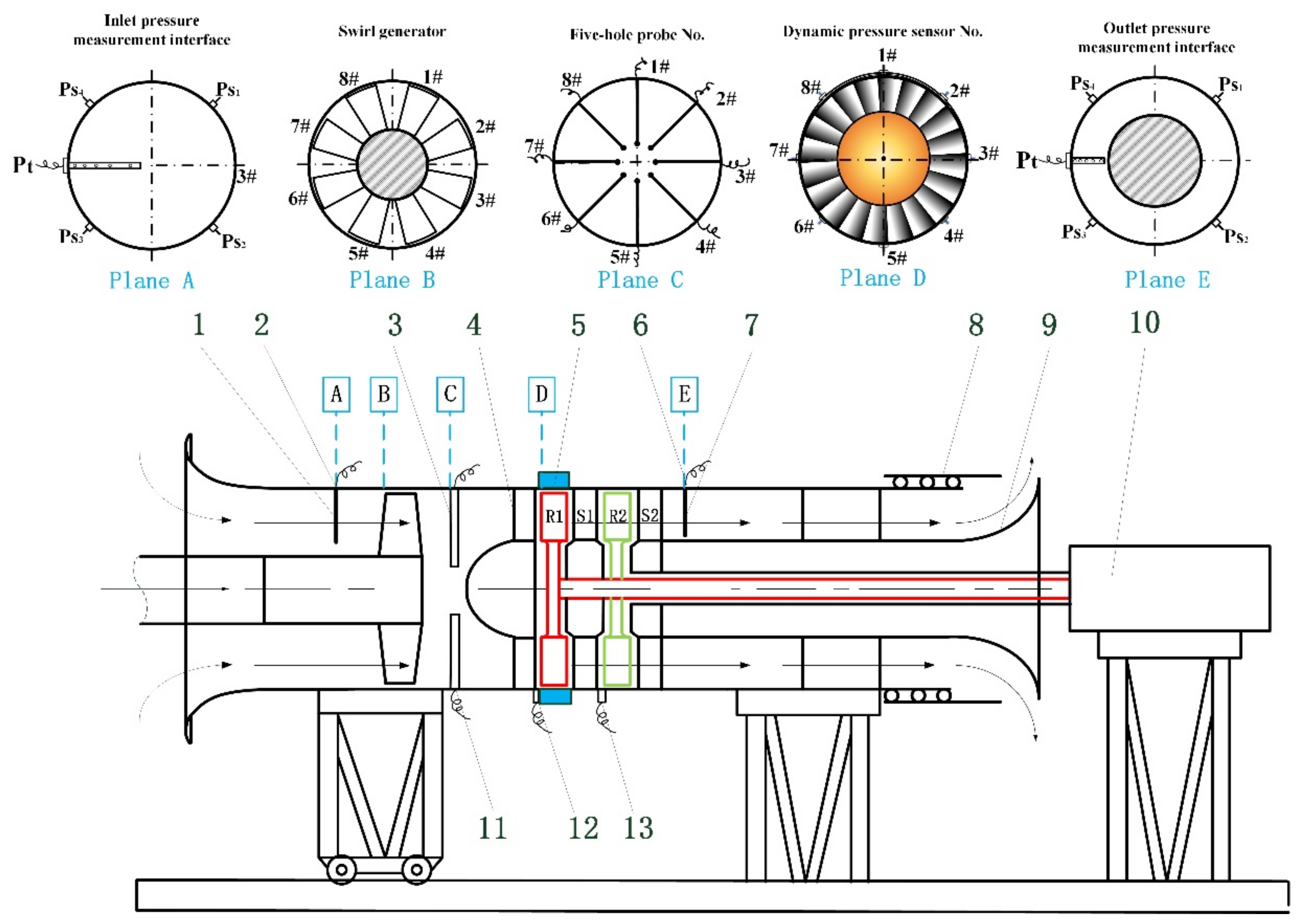
2. Experimental Facility and Sensors Equipment

2.1. Two-Stage Compressor TA66

The main purpose of our study is to investigate the influence of inlet swirl distortion on a military engine, which is a general multi-stage engine with a high hub ratio and IGVs installed; therefore, the corresponding experiments were conducted on a TA66 compressor with similar characteristics, i.e., a two-stage low-speed test compressor with IGVs. It was designed by the Fluid and Acoustic Engineering Laboratory of Beihang University, and had high-aspect-ratio ducts consisting of two identical stages and IGVs before the first stage. A schematic of the compressor is shown in Figure 1. The first- and second-stage rotors are colored in red and green, respectively. The IGV is labeled as item 4 in Figure 1. The casing treatment (item 5 in Figure 1) can be installed at the location of the half chord upstream of the first or second stage. There is an annular throttle (item 9 in Figure 1) installed at the outlet of the compressor and the nozzle area can be changed by adjusting the axial position of the controllable bleed valve (item 8 in Figure 1). This actuating device enables not only the quasi-static adjustment of the working condition to be achieved by moving it slowly from the operation point to the stall point, but also the stall state to be exited from quickly. The power of the compressor is supplied by an alternating current motor (item 10 in Figure 1) with a torque meter that can accurately measure the output power of the motor shaft. The detailed design parameters of the compressor are listed in Table 1. The installation angle of the IGV with the axis direction is 0 deg so that it can be considered as a straight plate with no pre-swirl.
To obtain the compressor characteristic curves and efficiency curves, the total and static pressures at the inlet (plane A in Figure 1) and outlet (plane E in Figure 1) of the compressor were captured by a total pressure comb (items 1 and 7 in Figure 1) and four static pressure taps (item 2 and 6 in Figure 1). It should be noted that the above sensors measuring pressure value are designed for steady-state flow and should be installed upstream of the distortion generator (plane B in Figure 1), the structure of which will be introduced in the following. The pressure sensors used here were 142PC01D Honeywell pressure sensors. The rated pressure range was 1 PSI between two pressure ports (one port is the atmosphere and another one measures total/static pressure), so in this work, the measured pressure was based on the reference atmospheric pressure. Five-hole probes with a transmission mechanism (item 3 in Figure 1) were installed downstream of the distortion generator to measure the velocity profile of the inlet flow field (plane C in Figure 1).
On the other hand, the development process of a rotating stall from the occurrence of stall precursor waves to fully developed cells with a sudden decrease in the pressure rise ratio was much shorter than the whole throttling process, about 0.2 s [26], so the above sensors, which were applied to measure the steady-state parameters, could not describe the process of the rotating stall. Therefore, to capture more flow information about the rotating stall, eight XT-190M-1D high-frequency-response dynamic pressure sensors (items 12 and 13 in Figure 1) were installed inlaid in the casing, about half a chord length upstream of the leading edge of the rotor around the circumferential direction with equal spacing. Its rated pressure was 1 PSI, and the sensitivity was about 5000.000 mV/PSI. The main data acquisition system was the NI-PXI system, and its maximum sampling rate was 100 kHz, which was sufficient to investigate the development process of the rotating stall. The filtered time history of the individual dynamic sensor could be used to calculate the modal information by performing mode decomposition in the circumference direction, which will be introduced further in the following section.

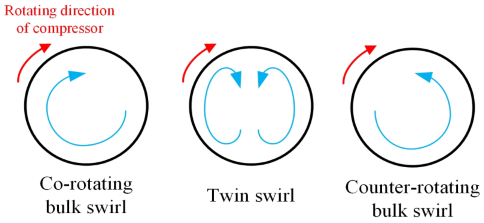
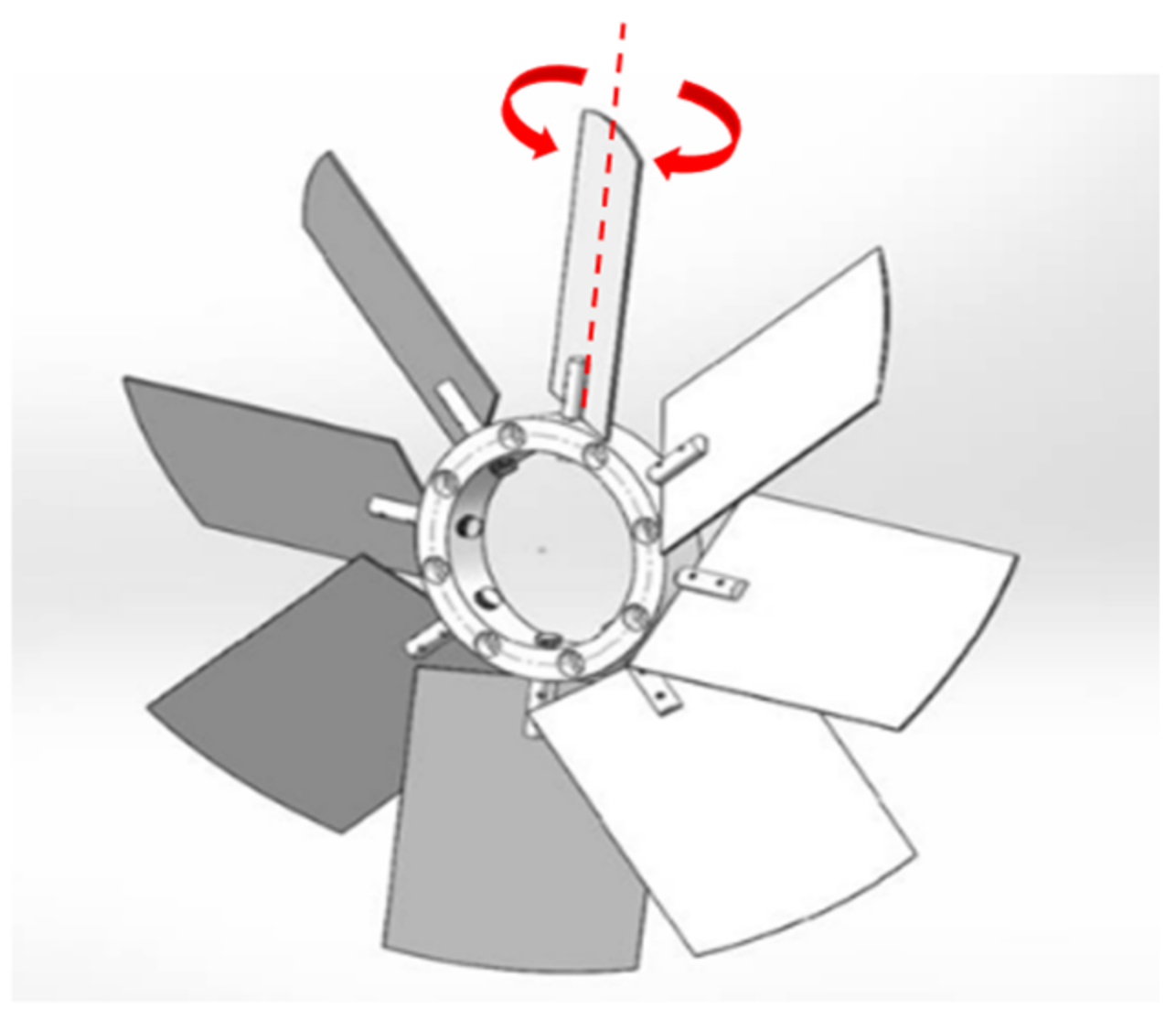
2.2. Swirl Distortion Generator

The fundamental characteristics of the swirl flow are shown in Figure 2. For the co-rotating and counter-rotating bulk swirl, the direction of the tangential velocity in the whole flow field is identical, but is, on the contrary, between the two parts of the twin swirl. Swirl directivity (SD) is proposed to assess the swirl rotational direction concerning the compressor rotation [6].
To investigate the influence of inlet swirl distortion, it is necessary to guarantee a similar flow pattern at the inlet interface of the compressor. The general approach is to install a swirl distortion generator in the straight inlet duct. Pazur et al. [12] used a delta wing to generate swirl flow and simulated different types of swirl by adjusting its pitch angle. Subsequently, more experiments adopted guide stream vane [27,28], the structures of which were created by numerical correlations. It can be observed that the essence of swirl flow is the existence of tangential flow velocity, and it can be achieved by the guide vanes. In our experiments, a distortion generator for the compressor TA66 was designed, as shown in Figure 3, and installed in the inlet ducts upstream of the compressor (Plane B of Figure 1) to simulate the flow pattern of the inlet swirl distortion. It contains eight straight guide vanes, and the axial established angle can be adjusted from 40 deg to −40 deg to simulate different types of swirl flow with various intensities. Here, the nomenclature of the type and intensity of inlet swirl distortion is based on the axial established angle of the guide vanes; for example, +10 means that the axial stagger angle of all vanes is 10 deg with the same rotation direction of the rotor, namely co-rotating bulk swirl, and −10 means counter-rotating bulk swirl with the opposite rotation direction of the rotor. Furthermore, +10−10 represents that the axial stagger angle of guide vanes #1–#4 is +10 deg and #5–#8 is −10 deg.
Eight five-hole probes (item 3 in Figure 1) were used to measure the velocity profile and total pressure fields of Plane C in Figure 1. The corresponding results are shown in Figure 4. The transducer is located at the top of the probe and its location in the radial direction can be adjusted by a transmission mechanism. Sixty data points in each circumferential position are collected, so there are 60 × 8 points in each figure. The arrow represents the velocity vector Vyz in the yz panel, and the swirl flow pattern can be clearly illustrated. The background contour illustrates the total pressure distribution. In Figure 4a, there is a bulk swirl flow with rotationally symmetric velocity, and the tangential velocity is highest in the medial part of the radius. The total pressure distribution is uniform in the circumferential direction, but nonuniform in the radial direction due to the different tangential velocity. In Figure 4b, there is a paired swirl that is nearly axially symmetric, but accompanied by an obvious nonuniform total pressure distribution. It can be concluded that the inlet swirl distortion is not only represented by the velocity distortion, but also the strong total pressure distortion. This phenomenon is in accordance with the total pressure distribution at the outlet of the S-duct captured by the numerical simulations [29]. Therefore, the influence of inlet swirl distortion is not only caused by the change in the angle of incidence of the rotor, but also by intense total pressure distortion, especially twin swirl distortion. This provides powerful support for our doubts about whether the negative effect induced by inlet swirl distortion can be eliminated by the installation of IGVs. The above distributions are consistent with the definition of swirl [11] and the experimental results [6], verifying the effectiveness and reliability of the swirl distortion generator. The flow fields under the conditions of +5 to +40, −5 to −40, and +5−5 to +20−20 were also measured. The results show that the intensity of tangential velocity and total pressure distortion increased with the vanes’ established angles in the swirl distortion generator.

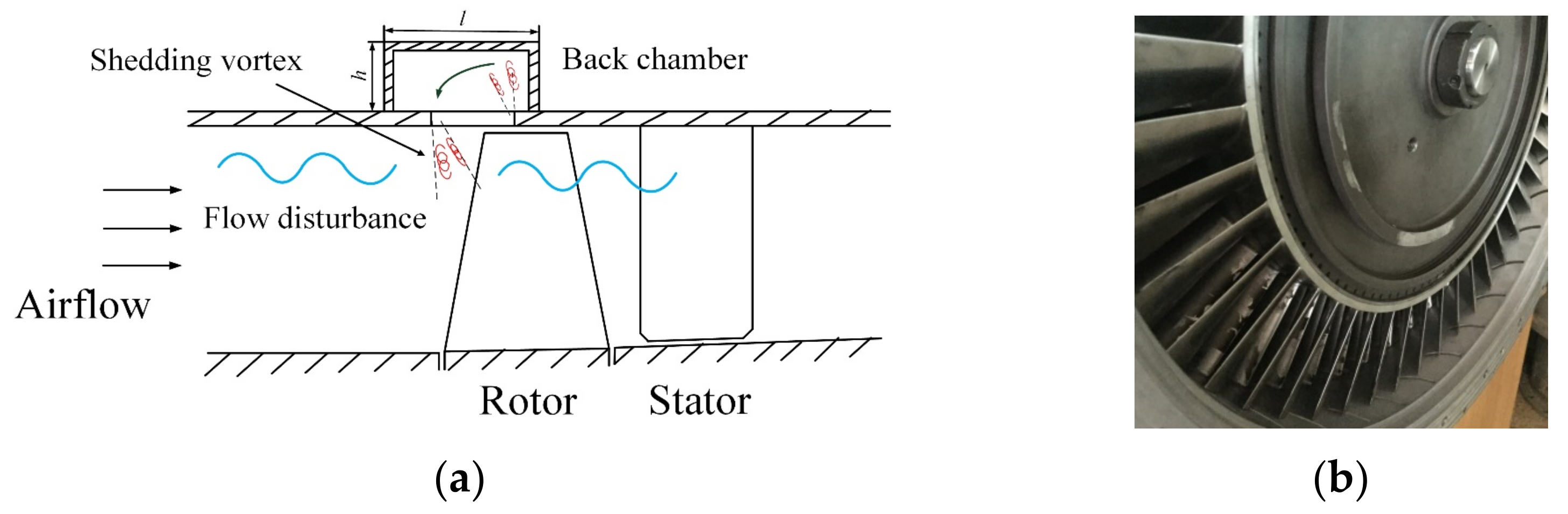
2.3. Stall Precursor-Suppressed (SPS) Casing Treatment

A schematic diagram of the SPS casing treatment is shown in Figure 5a. With the discovery of the stall precursor waves, the idea of increasing the stall margin by suppressing the nonlinear amplification of the stall precursor waves was applied in the active control [30]. However, the transient characteristics of the stall precursor waves and the slow response of actuating mechanical devices resulted in the active control being hard to apply in practice. The proposal of SPS casing treatment was inspired by introducing the above concept into passive control. A soft boundary condition can be constructed by the vortex–pressure wave interaction [31] between the stall precursor wave and the shedding vortex; then, the stall precursor waves can be weakened and the occurrence of the rotating stall can be delayed. The corresponding mechanism will be further investigated by the dynamic pressure signals captured by the dynamic sensors (item 12 in Figure 1) in the next section.
The structure of the SPS casing treatment consists of a perforated plate and a back chamber, which can be regarded as a Helmholtz resonator, as shown in Figure 5a. There was an annular back chamber (item 5 in Figure 1) with h = 65 mm and l = 82 mm in the casing wall. The perforated ratio of the SPS casing treatment could be adjusted from 0 to 12%, much smaller than that of conventional casing treatment (usually over 50%), which would significantly reduce the additional loss of efficiency and retain the characteristics of the pressure rise ratio. The slot connecting the main flow and the back chamber could be occluded by plastic plugs to be regarded as a solid casing wall. In a previous study [23], the geometry parameters, such as the camber height and perforated ratio, influenced the stall margin improvement of SPS casing treatment. It is installed about half a chord upstream of the rotor in one-stage compressors, but for multi-stage compressors, the installation location may also affect the stall margin improvement of SPS casing treatment. In our study, the effectiveness of SPS casing treatment was explored under conditions with various installation locations, including only the first stage, only the second stage, and both. Then the optimal strategy for enhancing the stall margin of the compressor was adopted under the inlet swirl distortion.

3. Experimental Results

3.1. Physical Parameters

The main parameters to assess the performance and stability of the compressor are defined as follows. The mass flow rate G is defined as
G = φ k A 1 P 1 T 1 q λ 1
where the correction coefficient φ = 0.992 is to correct the influence of the boundary layer and is obtained in the calibration process of the compressor [25], A1 is the sectional area of the inlet, k is the ratio of specific heat, P1* is the inlet’s total pressure, T1* is the inlet’s total temperature, and the stream function q(λ1) is obtained by the look-up table method. Then, the total-to-static pressure rise coefficient is defined as:
ψ = P 2 P 1 0.5 ρ 1 U m 2
where P2 is the static pressure at the outlet and Um represents the tangential speed at mid-span. The flow coefficient ϕ is denoted as
ϕ = V x U m = q v U m A 1
q v = φ A 1 2 P H P 1 ρ 1
where Vx is the axial velocity of the inlet profile, qv is the volume flow, ρ1 is inlet density, and PH* is the atmospheric pressure.
The efficiency η can be expressed as
η = q v P 2 P 1 1000 W E η E
where P2* is the total pressure at the stator exit, WE is the electrical power, and ηE is the motor power coefficient. It is measured by a torque meter, whose measurement accuracy is about 0.001 V. Moreover, the high measurement accuracy enables the error range of efficiency to be small enough.
Finally, SM is the stall margin, which is defined as where ‘d’ represents the design operating point and ‘s’ represents the rotating stall inception point,
S M = ψ s / ϕ s ψ d / ϕ d 1 × 100 %
Different from a compressor driven by a turbine in engineering, the operability of the compressor is driven by an alternating current motor (item 10 in Figure 1), so the method of drawing the operating line to ensure the design operating point is inappropriate for TA66. The flow coefficient ϕ and the efficiency η were multiplied to search for the design operating point with the maximum value. Therefore, the parameters of the design operating point of TA66 are ϕd = 0.292, ψd = 1.223, and ηd = 0.907.

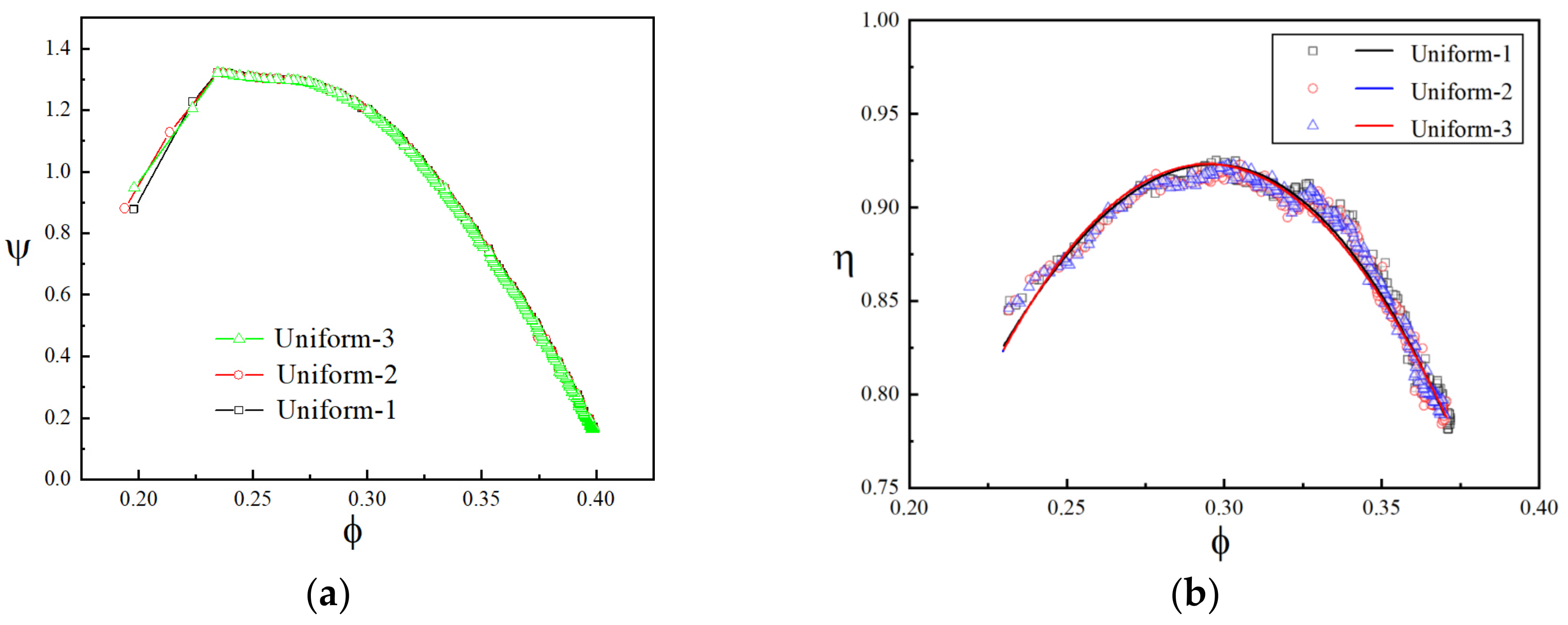
3.2. Experimental Repeatability

To guarantee the accuracy and reliability of the experimental results, a repetitive experiment was conducted to calculate the error range of the major parameters of the compressor. The total-to-static pressure rise curves and efficiency curves of three repetitive experiments under the uniform inlet condition are shown in Figure 6. The efficiency curves were reconstructed by three-order polynomial fitting. From the above results, it was confirmed that the experiments had great repeatability and the error range of the total-to-static pressure rise coefficient and efficiency was within our tolerance.

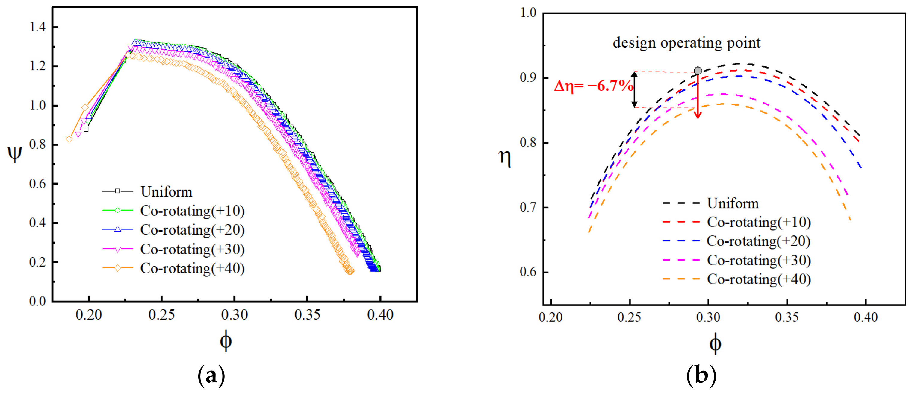
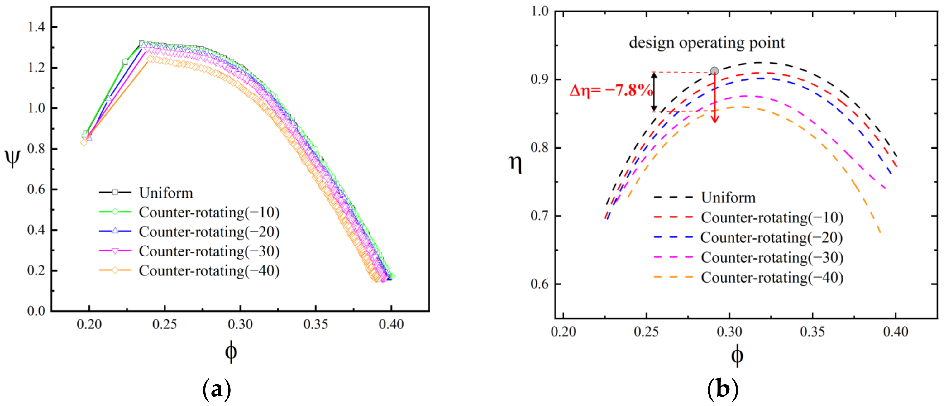
3.3. The Influence of Inlet Swirl Distortion on the TA66 with an IGV

In a previous study [15], experiments were carried out to explore the influences of inlet swirl distortion on a one-stage TA36 compressor without an IGV installed, and corresponding results are presented in Figure 7. It could be observed that −5 represented the counter-rotating swirl distortion of small intensity, which increased the compressive capacity of the compressor, and the co-rotating swirl distortion +5 and +10 always brought about detrimental effects on compressor performance. The characteristics of twin swirl distortion (+10−10) were different from those of bulk swirl distortions. They not only had a negative influence on the compressor performance, but they also caused a more serious decrease in the stall margin compared with the results of bulk swirl distortion. However, the decrease in the pressure rise was lower than that of the co-rotating bulk swirl distortion +10 because of the offset by the increase in the compressive capacity of the other part.
It can be concluded that the inlet swirl distortion brought about a great influence on the performance and stall margin of the compressor. The conventional treatment of military high-performance engines, generally designed as multi-stage with a high hub ratio, to eliminate the negative effect of inlet swirl distortion involves installing an IGV before the rotor of the first stage. As shown in Figure 4, because the inlet swirl distortion is also accompanied by strong nonuniform total pressure distortion, it is crucial to explore the influence of inlet swirl distortion after the installation of an IGV. Therefore, experiments on the two-stage TA66 compressor with the installation of an IGV under inlet swirl distortion were conducted as follows.
Figure 8 shows the total–static pressure rise curves and efficiency curves of the compressor under the co-rotating bulk swirl distortion, and the axial angle of the swirl generator blades from 0 to +40 represents various intensities of distortion (for ease of observation, not all conditions are displayed here). The black curve represents the condition where the axial angles of the generator blades are 0 deg, i.e., the uniform inlet condition. When the intensity of the bulk swirl distortion is small, such as +10, there is almost no influence on the pressure rise curve of the compressor, along with slight efficiency loss. However, for the bulk swirl distortion with large intensity, such as +40, it can still bring about detrimental effects on the compressive capacity of the compressor. The efficiency decreased by 6.7%, but the stall margin hardly changed. Figure 9 shows the curves of the compressor under the counter-rotating bulk swirl distortion. The whole variance trend of curves with small intensity was almost the same as the condition under co-rotating bulk swirl distortion. Meanwhile, for the condition with high intensity, such as the −40 curve, the efficiency loss decreased by 7.8% and it was obvious that the instability boundary moved right and the stall margin decreased. This differs from the results that the counter-rotating bulk swirl distortion could improve the compressive capacity of the compressor without an IGV. Therefore, under bulk swirl distortion, whether co-rotating or counter-rotating, when the distortion intensity was not large enough, there was hardly any influence of swirl distortion on the compressive capacity of the compressor alone along with little efficiency loss, because the tangential velocity of the swirl flow could be eliminated by IGV, to some degree. When the intensity of swirl distortion increased, the flow through the IGV remained at a degree of tangential velocity, which still influenced the performance of the compressor. Due to the strong interactions between the fluid and IGV, the flow loss increased, leading to a decrease in compressive capability and significant efficiency loss. Therefore, the installation of the IGV was effective to eliminate the negative influence of inlet bulk swirl distortion when the intensity of distortion was low. If the intensity was high enough, IGVs could only alleviate the negative influence to some extent.
Figure 10 shows the total–static pressure rise curves and efficiency curves of the compressor under twin swirl distortion. The black curve represents uniform inlet conditions. Under the condition +10−10, at the large flow coefficient point, there was no obvious change in the compressive capability, but the stall occurred in advance, and the stall margin and efficiency decreased obviously. Compared with the results of the bulk swirl distortion as shown in Figure 8 and Figure 9, the tangential velocity of swirl flow under the conditions of +10 or −10 could almost be eliminated by the IGV; then, under the condition of +10−10, it could also be eliminated. Therefore, according to the inlet total pressure distribution, as shown in Figure 4, it can be inferred that the decrease in the stall margin and efficiency may have been caused by the total pressure distortion, but it had no obvious influence on the compressive capability. With the increase in the distortion intensity to +20−20, the compressive capability began to decrease and the stall margin decreased further, which was also attributed to the total pressure distortion. Conventional cognition may take it for granted that the twin swirl can simply be considered as a superposition of the co- and counter-rotating swirls. However, the twin swirl distortion will still bring about a negative influence on the performance and stall margin of the compressor, even with the installation of an IGV.
For the two-stage compressor with an IGV installed, the influence of bulk swirl distortion was slight because the tangential velocity of swirl flow could be eliminated by the IGV, as expected [11]. Nevertheless, for the twin swirl with the same tangential velocity, due to the accompanying total pressure distortion, there still existed a significantly negative influence. It has been observed that the type of swirl distortion generated by an S-duct depends on the geometric parameters of the S-duct [4]; therefore, even in a military engine with an IGV, inlet twin swirl distortion could be avoided by adjusting the geometric parameters of the S-duct.

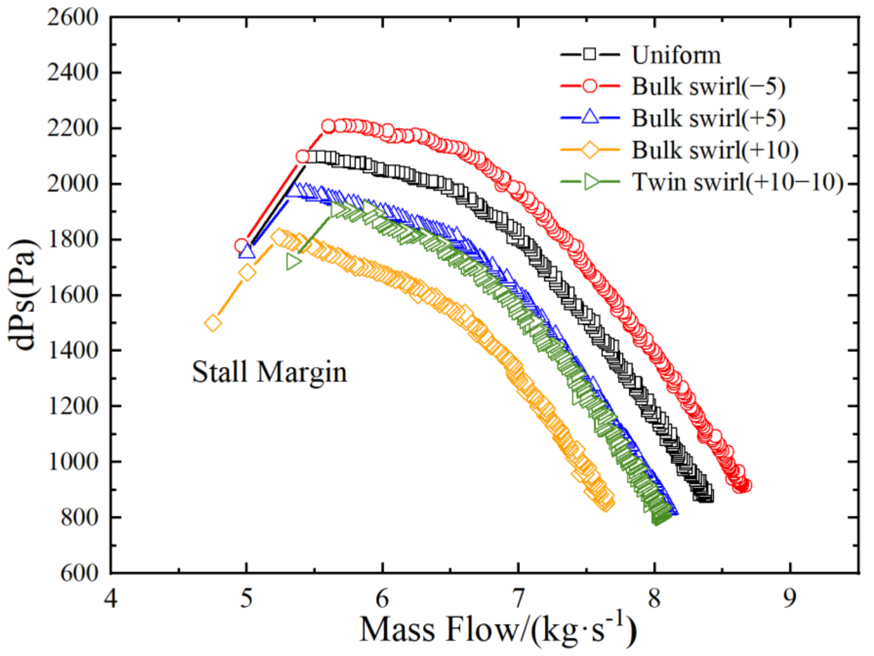
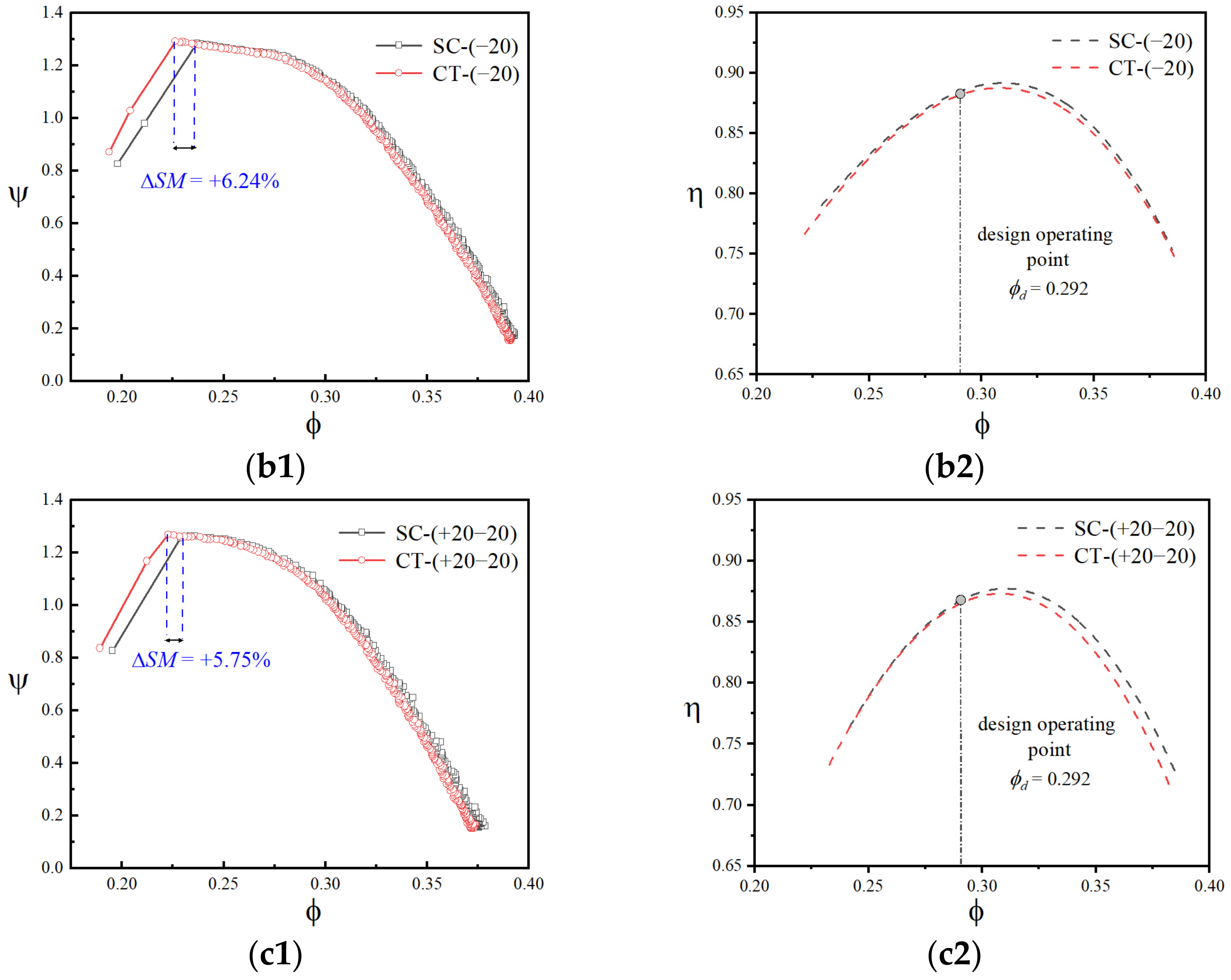
3.4. Stall Margin Enhancement of SPS Casing Treatment

The above results show that inlet swirl distortion influenced the performance and stall margin of the compressor, especially twin swirl distortion. Therefore, SPS casing treatment was installed for TA66 to explore its stabilization ability on the multi-stage compressor under inlet swirl distortion.
In one-stage compressors, the SPS casing treatment is generally installed upstream of the rotor [15]. However, in the TA66 two-stage compressor, the SPS casing treatment can be installed in the first stage, the second, or both. Therefore, the influence of installation location on the stall margin enhancement of the SPS casing treatment was first investigated, along with various perforation ratios, under uniform inlet conditions to explore the best installation strategy. As shown in Figure 11, when the SPS casing treatment was installed in the first stage, the stall margin improvement increased with the perforation ratio. Nevertheless, when the SPS casing treatment was only installed in the second stage, there was a negative effect on the stall margin. It can be inferred that the stall precursor first occurs in the first stage, which will be verified by the dynamic signals discussed in the following. According to its short length scale and high frequency, it cannot infinitely spread throughout the duct in the axial direction. Compared with the case with the installation only in the first stage, there were only a few additional SM benefits when SPS casing treatment was installed in both stages, but they were accompanied by obvious additional efficiency loss. Above all, the best strategy for the installation of SPS casing treatment was in the first stage with a perforation ratio of 12%.
To explore the mechanism of the SPS casing treatment, it was necessary to capture the perturbation evolution in the pre-stall process after the installation of the SPS casing treatment. The collection of dynamic pressure data was activated when the operating condition was close to the stall inception point; then, the throttle moved slowly so that the stall could occur within 10–20 s. The time-resolved pressure signals of the case in which the sensors (items 12 and 13 in Figure 1) were placed near the rotor tip of both stages are shown in Figure 12 under uniform inlet conditions. The static pressure signals of 16 channels were non-dimensional and the horizontal axis represented the physical time with throttling. The stall precursor could be first found in the first stage at about 15.2 s; then, it propagated in the circumferential direction and could also be captured by the other sensors. After two rotor cycles of about 0.08 s, perturbation also occurred in the second stage as the blue dashed line. This could be the reason why it was more effective when the SPS casing treatment was installed in the first stage.
Then, the SPS casing treatment was applied to the condition with inlet swirl distortion. The total-to-static pressure curves and efficiency curves treated by three-order polynomial fitting with a solid wall and SPS casing treatment are shown in Figure 13. It can be observed that, after the SPS casing treatment was installed, the stall margin increased by 6–7% and the compressor performance was barely influenced. Under various types of inlet swirl distortion, the stall margin improvement of the compressor was roughly identical, and it was demonstrated that the stall margin improvement mechanism of SPS casing treatment was insensitive to the inlet swirl flow pattern of the compressor. Furthermore, as shown in the efficiency curves, there was only a slight additional efficiency loss, which was even lower than the numerical error and was perfectly acceptable compared with conventional casing treatment, so it could be argued that the effectiveness of the stall margin improvement of the SPS casing treatment was verified and it had almost no obvious negative influence on the performance of the compressor under various types of swirl distortion, which is a great improvement of the existing stabilization methods.
Subsequently, the above time-resolved signals captured by the high-frequency dynamic sensors, as shown in Figure 12, can be used to calculate the modal information by mode decomposition in the circumference direction. The dynamic signals in the circumferential direction can be regarded as a superposition of each circumferential perturbation mode, and the time-varying information of a specific circumferential mode can be obtained by the spatial Fourier transformation, which can be expressed as
C k ( t ) = 1 N n = 0 N 1 p n ( t ) exp 2 i k n π N
where N = 8. C1(t) is the first-order perturbation mode. The phenomenon in the experiments [32] was that the most unstable mode corresponded to the first spatial harmonics of the perturbations in the compressor, and when it was stabilized, the operating flow range increased, so the first-order mode was proven to be the predominant circumferential perturbation mode. To illustrate the perturbation evolution, the time-varying signal was first filtered to eliminate the influence of shaft-frequency and high-frequency noise. Then, the fast Fourier transformation and power spectrum density (PSD) were applied to obtain the energy spectrum. The formulas of the process are represented as
F k ( ω ) = F F T ( C k ( t ) )
P S D = 10 lg ( F ( ω ) 2 n 2 )
Defining the normalized relative frequency as the ratio of the perturbation frequency to the shaft frequency, the PSD results under various types of swirl distortions are shown in Figure 14 and the amplitude peaks of the perturbation mode are also marked. To clearly distinguish the differences in peak amplitude between the SPS casing treatment and solid wall, the traditional three-dimensional spectrum, including the time process [15], was projected to a two-dimensional frequency spectrum with the coordinates of frequency and amplitude. The left column represented the cases with solid casing and the right represented those with the installation of the SPS casing treatment. It can be observed that the relative frequency of maximum perturbation amplitude was about 0.4 with bulk swirl distortion and 0.6 with twin swirl distortion. The peak of the perturbation energy decreased after the installation of the SPS casing treatment. Though the perturbation energy slightly increased at some individual relative frequencies, the perturbation energy decreased obviously on the whole. The SPS casing treatment could be analogous to the non-local reacting liners, which could be regarded as a kind of impedance boundary. The above results reflect its broadband characteristics, so it was insensitive to the frequency of flow disturbances and flow details [33]. The effectiveness of the SPS casing treatment under the inlet swirl distortion verified that it could absorb the pressure perturbation energy and suppress the nonlinear amplification of the pressure perturbation, including the stall precursors, to delay the occurrence of rotating stall.

4. Conclusions

In this study, the influence of inlet swirl distortion on a two-stage TA66 compressor with an IGV installed was investigated. SPS casing treatment was applied to improve the stall margin under the inlet swirl distortion and the corresponding mechanism was also explored. The conclusions can be summarized as follows:
(1)
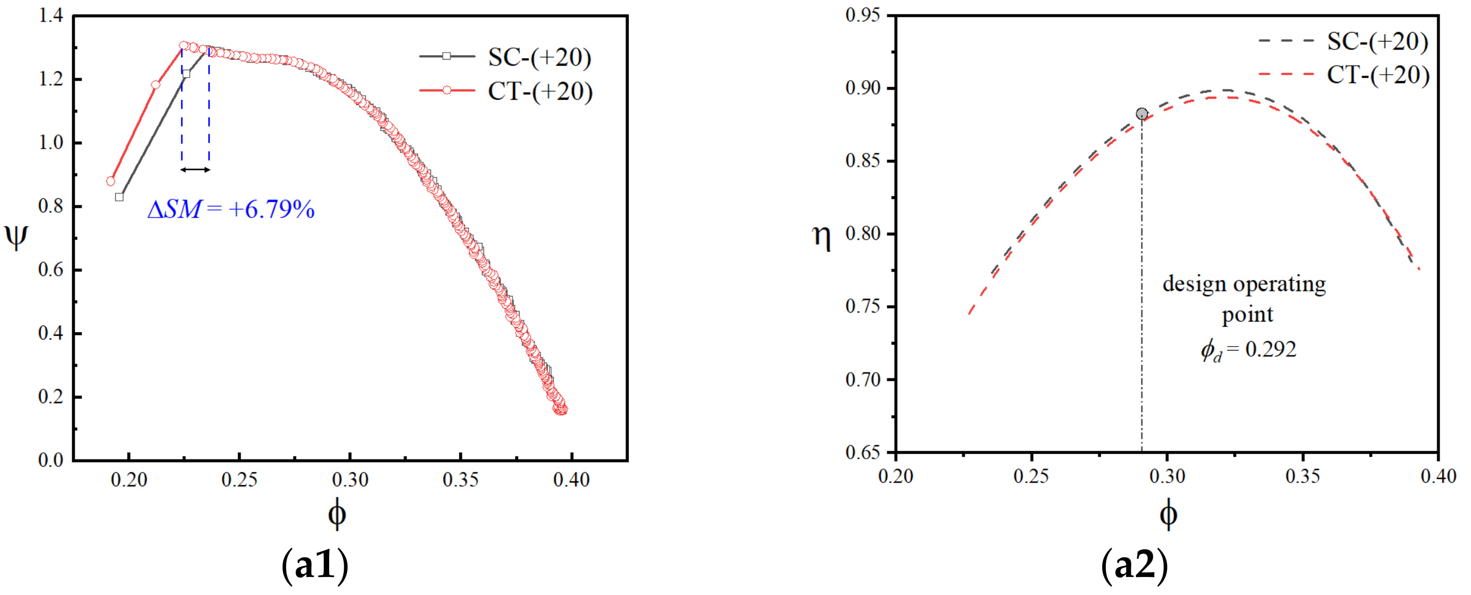
For the multi-stage compressor with an IGV installed, under the inlet bulk swirl distortion with low intensity, there was almost no negative influence on the compressive capability and stall margin of the compressor. When the distortion intensity further increased, there was still a decrease in the compressive capability and obvious additional efficiency loss.
(2)
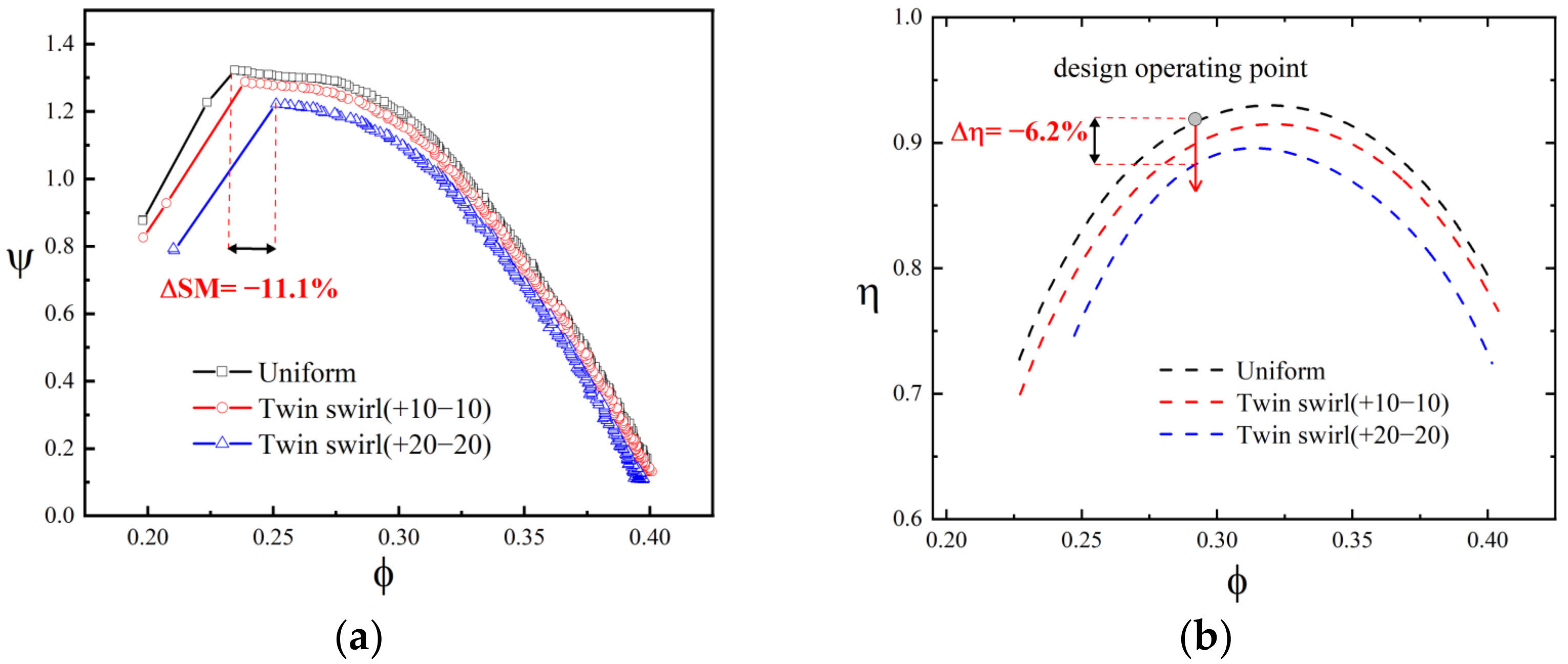
Under the inlet twin swirl distortion, even with the installation of an IGV, there still existed a significantly negative influence on the multi-stage compressor, especially the stall margin. This might have been caused by the accompanying total pressure distortion induced by the twin swirl flow. The inlet twin swirl distortion could be avoided by adjusting the geometric parameters of the S-duct in engineering.
(3)
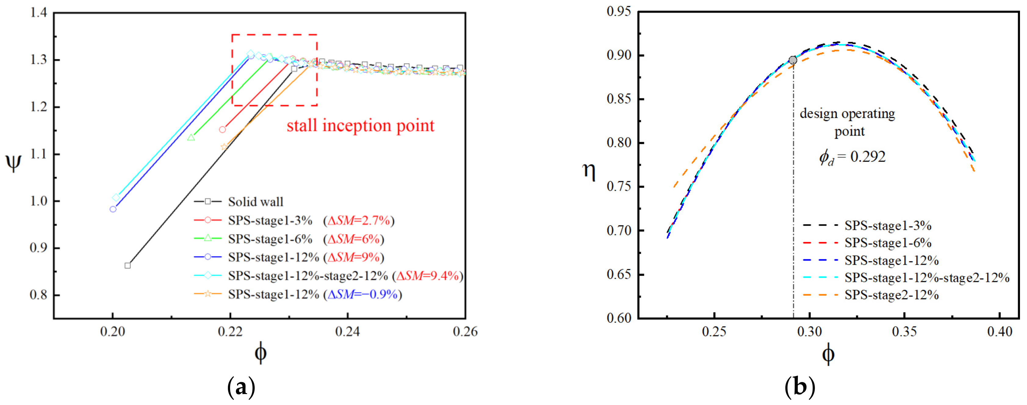
The best strategy for the installation of SPS casing treatment is to install it in the first stage to guarantee sufficient stall margin improvement and minimum efficiency loss. In this way, it can improve the stall margin of the compressor with no change in the characteristic curves and no additional efficiency loss under various types of inlet swirl distortions.
(4)
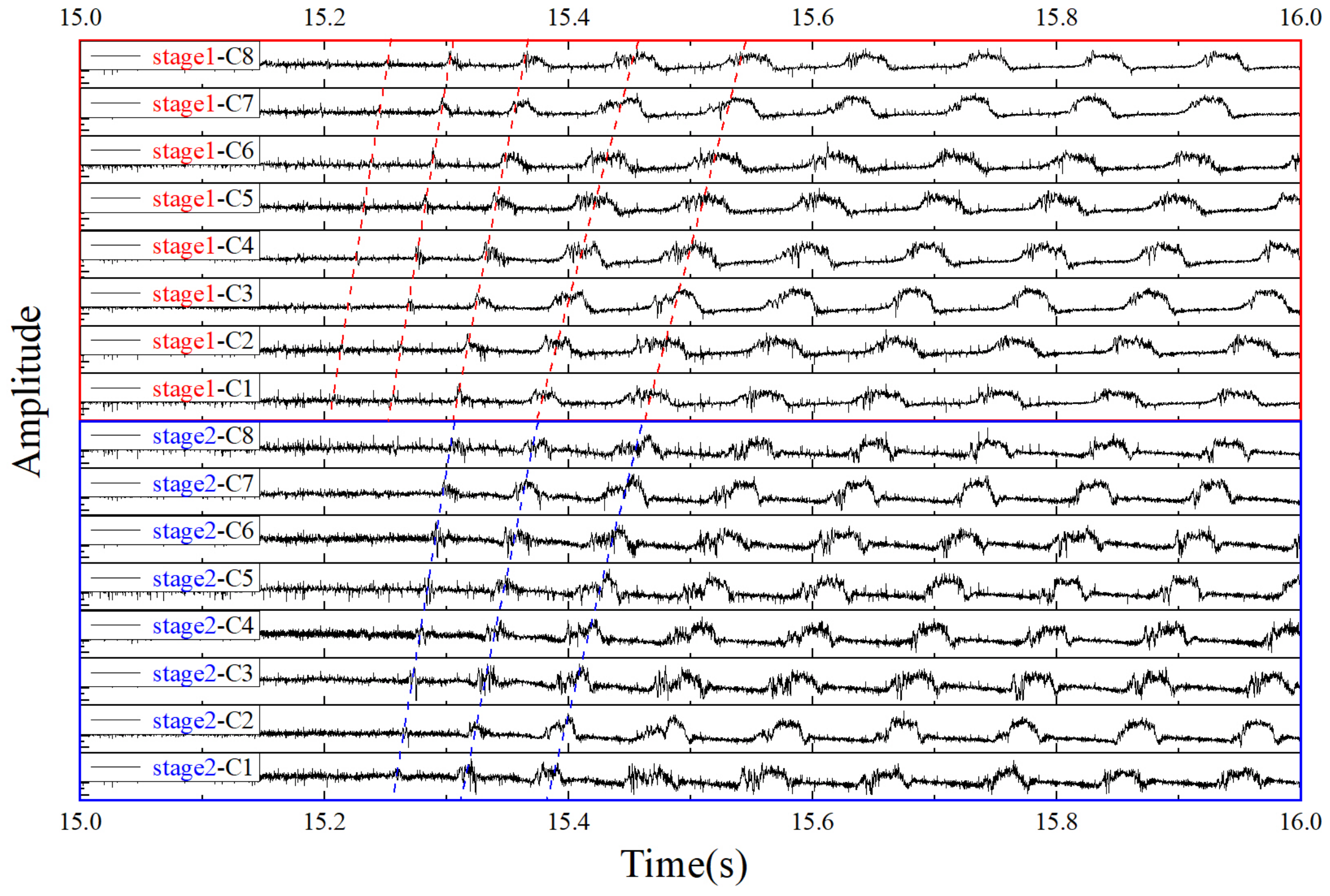
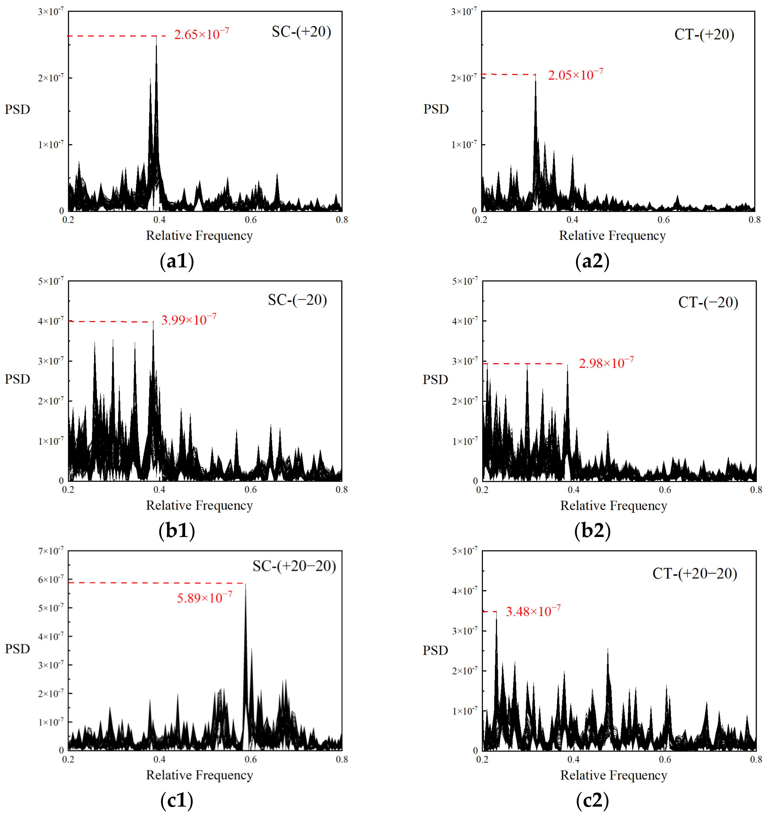
The mechanism of SPS casing treatment was verified by the dynamic pressure signals and PSD analysis to absorb the pressure perturbation energy and suppress the nonlinear amplification of the pressure perturbation, including the stall precursors, to delay the occurrence of rotating stall.

Author Contributions

Conceptualization, Y.F. and X.D.; methodology, Y.F. and X.D.; software, D.S. and X.D.; validation, Y.F.; formal analysis, Y.F. and X.D.; investigation, Y.F.; resources, D.S. and X.D.; data curation, Y.F.; writing—original draft preparation, Y.F.; writing—review and editing, Y.F., D.S. and X.D.; visualization, Y.F.; supervision, X.S.; project administration, X.S.; funding acquisition, D.S., X.D. and X.S. All authors have read and agreed to the published version of the manuscript.

Funding

The research presented here is supported by Science Center for Gas Turbine Project (P2022-A-II-002-001, P2022-C-II-003-001), National Science and Technology Major Project (2017-II-0005-0018), the Key Laboratory of Pre-Research Management Center (6142702200101).

Data Availability Statement

Not applicable.

Conflicts of Interest

The authors declare no conflict of interest.

References

  1. Goldsmith, E.L. Intake Aerodynamics; Blackwell Science: Oxford, UK, 1985. [Google Scholar]
  2. Manas, M.P.; Pradeep, A.M. Stall Inception in a Contra-Rotating Fan under Radially Distorted Inflows. Aerosp. Sci. Technol. 2020, 105, 105909. [Google Scholar] [CrossRef]
  3. Tamaki, T.; Nagano, S. Effects of Inlet Distortions on a Multi-Stage Compressor<149>transonic Flow Pressure Distortion. In Proceedings of the AIAA 4th International Symposium on Air Breathing Engines, Orlando, FL, USA, 1–6 April 1979. [Google Scholar]
  4. Gil-Prieto, D.; Zachos, P.K.; MacManus, D.G.; McLelland, G. Unsteady Characteristics of S-Duct Intake Flow Distortion. Aerosp. Sci. Technol. 2019, 84, 938–952. [Google Scholar] [CrossRef]
  5. Stocks, C.P.; Bissinger, N.C. Design and Development of the Tornado Engine Air Intake. In Proceedings of the AGARD Conference Proceedings, Turin, Italy, 29 September–3 October 1981. [Google Scholar]
  6. Sheoran, Y.; Bouldin, B.; Krishnan, P.M. Compressor Performance and Operability in Swirl Distortion. J. Turbomach. 2011, 134, 1–13. [Google Scholar] [CrossRef]
  7. Kapoor, K.; Anderson, B.; Reddy, D. A Comparative Study of Full Navier-Stokes and Reduced Navier-Stokes Analyses for Separating Flows within a Diffusing Inlet S-Duct. In Proceedings of the 29th Joint Propulsion Conference and Exhibit, Monterey, CA, USA, 28–30 June 1993. [Google Scholar]
  8. Anderson, B.H.; Reddy, D.R.; Kapoor, K. Study on Computing Separating Flows within a Diffusion Inlet S-Duct. J. Propuls. Power 1994, 10, 661–667. [Google Scholar] [CrossRef]
  9. Verma, A.; Jang, H.; Mahesh, K. The Effect of an Upstream Hull on a Propeller in Reverse Rotation. J. Fluid Mech. 2012, 704, 61–88. [Google Scholar] [CrossRef]
  10. Milidonis, K.; Semlitsch, B.; Hynes, T. Effect of Clocking on Compressor Noise Generation. AIAA J. 2018, 56, 4225–4231. [Google Scholar] [CrossRef]
  11. Inlet, A.; Distortion, S. AIR5686—A Methodology for Assessing Inlet Swirl Distortion; SAE International: Warrendale, PA, USA, 2017. [Google Scholar] [CrossRef]
  12. Pazur, W.; Fottner, L. The Influence of Inlet Swirl Distortions on the Performance of a Jet Propulsion Two-Stage Axial Compressor. J. Turbomach. 1991, 113, 233. [Google Scholar] [CrossRef]
  13. Schmid, N.R.; Leinhos, D.C.; Fottner, L. Steady Performance Measurements of a Turbofan Engine with Inlet Distortions Containing Co- And Counterrotating Swirl from an Intake Diffuser for Hypersonic Flight. J. Turbomach. 2001, 123, 379–385. [Google Scholar] [CrossRef]
  14. Rademakers, R.P.M.; Bindl, S.; Niehuis, R. Effects of Flow Distortions as They Occur in S-Duct Inlets on the Performance and Stability of a Jet Engine. J. Eng. Gas Turbines Power 2016, 138, 1–10. [Google Scholar] [CrossRef]
  15. Dong, X.; Sun, D.; Li, F.; Jin, D.; Gui, X.; Sun, X. Effects of Stall Precursor-Suppressed Casing Treatment on a Low-Speed Compressor with Swirl Distortion. J. Fluids Eng. Trans. ASME 2018, 140, 1091–1101. [Google Scholar] [CrossRef]
  16. Sheoran, Y.; Bouldin, B. A Versatile Design of a Controlled Swirl Distortion Generator for Testing Gas Turbine Engines. In Proceedings of the ASME Turbo Expo, Berlin, Germany, 9–13 June 2008; Volume 1, pp. 81–92. [Google Scholar]
  17. Sheoran, Y.; Bouldin, B.; Krishnan, P.M. Advancements in the Design of an Adaptable Swirl Distortion Generator for Testing Gas Turbine Engines. In Proceedings of the ASME Turbo Expo, Orlando, FL, USA, 8–12 June 2009; Volume 1, pp. 23–32. [Google Scholar]
  18. Chue, R.; Hynes, T.P.; Greitzer, E.M.; Tan, C.S.; Longley, J.P. Calculations of Inlet Distortion Induced Compressor Flow Field Instability. Int. J. Heat Fluid Flow 1989, 10, 211–223. [Google Scholar] [CrossRef]
  19. Greitzer, E.M.; Moore, F.K. A Theory of Post-Stall Transients in Axial Compression Systems: Part II—Application. J. Eng. Gas Turbines Power 1986, 108, 68–76. [Google Scholar] [CrossRef]
  20. Dong, X.; Sun, D.; Li, F.; Sun, X. Stall Margin Enhancement of a Novel Casing Treatment Subjected to Circumferential Pressure Distortion. Aerosp. Sci. Technol. 2018, 73, 239–255. [Google Scholar] [CrossRef]
  21. Takata, H.; Tsukuda, Y. Stall Margin Improvement by Casing Treatment—Its Mechanism and Effectiveness. J. Eng. Power Trans. ASME 1977, 99, 121–133. [Google Scholar] [CrossRef]
  22. Kroeckel, T.; Hiller, S.J.; Jeschke, P. Application of a Multistage Casing Treatment in a High Speed Axial Compressor Test Rig. In Proceedings of the Proceedings of the ASME Turbo Expo, Vancouver, BC, Canada, 6–10 June 2011. [Google Scholar]
  23. Sun, D.; Liu, X.; Jin, D.; Gui, X.; Sun, X. Theory of Compressor Stability Enhancement Using Novel Casing Treatment, Part II: Experiment. J. Propuls. Power 2014, 30, 1236–1247. [Google Scholar] [CrossRef]
  24. Sun, X.; Sun, D.; Liu, X.; Yu, W.; Wang, X. Theory of Compressor Stability Enhancement Using Novel Casing Treatment, Part I: Methodology. J. Propuls. Power 2014, 30, 1224–1235. [Google Scholar] [CrossRef]
  25. Dong, X.; Sun, D.; Li, F.; Jin, D.; Gui, X.; Sun, X. Effects of Rotating Inlet Distortion on Compressor Stability with Stall Precursor-Suppressed Casing Treatment. J. Fluids Eng. Trans. ASME 2015, 137, 1–15. [Google Scholar] [CrossRef]
  26. McDougall, N.M.; Cumpsty, N.A.; Hynes, T.P. Stall Inception in Axial Compressors. J. Turbomach. 1990, 112, 116–123. [Google Scholar] [CrossRef]
  27. Hoopes, K.M.; O’Brien, W.F. The Streamvane© Method: A New Way to Generate Swirl Distortion for Jet Engine Research. In Proceedings of the 49th AIAA/ASME/SAE/ASEE Joint Propulsion Conference, San Jose, CA, USA, 14–17 July 2013; pp. 1–11. [Google Scholar] [CrossRef]
  28. Frohnapfel, D.J.; Todd Lowe, K.; O’Brien, W.F. Experimental Quantification of Fan Rotor Effects on Inlet Swirl Using Swirl Distortion Descriptors. J. Eng. Gas Turbines Power 2018, 140, 1–8. [Google Scholar] [CrossRef]
  29. Wellborn, S.R.; Wellborn, B.A.; Okiishi, T.H. Study of the Compressible Flow in a Diffusing S-Duct. J. Propuls. Power 1994, 10, 668–675. [Google Scholar] [CrossRef]
  30. Williams, J.E.F. Review Lecture—Anti-Sound. Proc. R. Soc. London. A. Math. Phys. Sci. 1984, 395, 63–88. [Google Scholar] [CrossRef]
  31. Jing, X.; Sun, X. Effect of Plate Thickness on Impedance of Perforated Plates with Bias Flow. AIAA J. 2000, 38, 1573–1578. [Google Scholar] [CrossRef]
  32. Wetgt, H.J.; Paduano, J.D.; Fréchette, L.G.; Epstein, A.H.; Greitzer, E.M.; Bright, M.M.; Strazisar, A.J. Active Stabilization of Rotating Stall and Surge in a Transonic Single Stage Axial Compressor. In Proceedings of the ASME Turbo Expo, Orlando, FL, USA, 2–5 June 1997; Volume 4. [Google Scholar]
  33. Jing, X.; Wang, X.; Sun, X. Broadband Acoustic Liner Based on the Mechanism of Multiple Cavity Resonance. AIAA J. 2007, 45, 2429–2437. [Google Scholar] [CrossRef]
Figure 1. Schematic of the structure and measurement arrangement of the two-stage TA66 with an IGV.
Aerospace 10 00141 g001
Figure 2. Schematic of three types of swirl flow patterns.
Aerospace 10 00141 g002
Figure 3. Structure of the swirl distortion generator.
Aerospace 10 00141 g003
Figure 4. Inlet total pressure and velocity profile Vyz under the conditions of (a) +10 (co-rotating bulk swirl distortion) and (b) +10−10 (twin swirl distortion).
Aerospace 10 00141 g004
Figure 5. (a) Schematic diagram and (b) installation status of SPS casing treatment.
Aerospace 10 00141 g005
Figure 6. Repetitive experiment results of the (a) total-to-static pressure rise curves and (b) efficiency curves of the TA66 compressor.
Aerospace 10 00141 g006
Figure 7. Static pressure rise curve with various inlet swirl distortion types under 100% design speed.
Aerospace 10 00141 g007
Figure 8. (a) Total-to-static pressure rise curves and (b) efficiency curves under the inlet co-rotating bulk swirl distortion.
Aerospace 10 00141 g008
Figure 9. (a) Total-to-static pressure rise curves and (b) efficiency curves under the inlet counter-rotating bulk swirl distortion.
Aerospace 10 00141 g009
Figure 10. (a) Total-to-static pressure rise curves and (b) efficiency curves under the inlet twin swirl distortion.
Aerospace 10 00141 g010
Figure 11. (a) Total-to-static pressure rise curves and (b) efficiency curves with various SPS casing treatment strategies.
Aerospace 10 00141 g011
Figure 12. Dynamic static pressure signals in the evolution of rotating stall.
Aerospace 10 00141 g012
Figure 13. Total-to-static pressure rise curves (1) and efficiency curves (2) without/with SPS casing treatment under inlet swirl distortion of (a) +20, (b) −20, and (c) +20−20.
Aerospace 10 00141 g013aAerospace 10 00141 g013b
Figure 14. PSD of dynamic pressure signal by normalized frequency without (1)/with (2) SPS casing treatment under various inlet swirl distortions of (a) +20, (b) −20, and (c) +20−20.
Aerospace 10 00141 g014
Table 1. Design parameters of the two-stage compressor TA66 with IGVs.
Structural parameters
IGV1-Rotor1-Stator2-Rotor2-Stator
Blade number3847454745
Installation angle
with axis direction
60°10°60°10°
Diameter (mm)600
Aspect ratio1.69
Blade ratio0.7
Performance parameters at the operating point
Mass rate m ˙ d (kg/s)7.25Rotating speed (rpm)3000
Flow coefficient ϕ d 0.267Pressure rise coefficient ψ d 1.176
Rated power (kW)16Efficiency η d 0.92
Pressure ratio1.056Static pressure rise p 2 p 1 (Pa)4600
Tip clearance (mm)0.6–0.8Tangential velocity at blade tip U t (m/s)94.2
Rotor–stator gap (mm)8–20
Disclaimer/Publisher’s Note: The statements, opinions and data contained in all publications are solely those of the individual author(s) and contributor(s) and not of MDPI and/or the editor(s). MDPI and/or the editor(s) disclaim responsibility for any injury to people or property resulting from any ideas, methods, instructions or products referred to in the content.

