Article

Effect of the Particle Size Distribution of Irregular Al Powder on Properties of Parts for Electronics Fabricated by Binder Jetting

Faculty of Materials Engineering and Physics, Cracow University of Technology, Warszawska 24, 31-155 Cracow, Poland
*
Author to whom correspondence should be addressed.
Electronics 2023, 12(12), 2733; https://doi.org/10.3390/electronics12122733
Submission received: 19 May 2023 / Revised: 14 June 2023 / Accepted: 15 June 2023 / Published: 19 June 2023
(This article belongs to the Special Issue New Trends in 3D Printing for Novel Materials)

Abstract

:
The present work analyzed the influence of the particle size of irregular aluminum powder on the properties of Binder-Jetting-printed parts, which can be used as electronic components. Powders of various particle sizes as well as blends in the ratio of 73–27 wt.% or 27–73 wt.% of coarse to fine powder particles were used. The parts were printed with constant parameters, such as a layer thickness of 120 µm, roller traverse speed of 10 mm/s, and binder saturation of 80%. For parts made of individual blends, analysis of the XRD, density, porosity, surface roughness, and dimensional changes in X, Y, and Z axes after the sintering process was conducted. The results confirmed the trend of smoothing the surface of 3D-printed parts with a reduction in the size of the powder particles used. The best results in terms of surface roughness were obtained for powder in which coarse particles (73%) had 50 µm and fine particles (27%) had 20 µm. However, the incorporation of coarser particles in an amount of 27 wt.% (AL160) to the fine-grained powder base (ALC100) allowed for the obtaining of details with higher density, lower total porosity, and relatively low surface roughness. The combination of these two powder particle sizes allowed the fine powder to fill the voids between the larger particles, resulting in properties that represent an excellent relationship between density, porosity, and surface quality. The research results indicate that the three-dimensional parts produced by Binder Jetting technology, through the phenomenal thermal conductivity of aluminum, can be successfully used as electronic components, such as heat sinks or transistor housings.

1. Introduction

In recent decades, additive manufacturing (AM) technology, commonly known as 3D printing, has gained a lot of interest as it offers an excellent alternative to conventional manufacturing methods. It allows the creation of parts with complex structures without the need for post-processing, which ensures a more flexible production process. It results in economic benefits [1,2,3,4].
Additive manufacturing enables the fabrication of three-dimensional parts based on previously designed digital CAD models [5]. The finished object is divided into layers and the path of the tool that builds the subsequent layers is determined. The process is repeated layer by layer until the designed part is completed [6]. Three-dimensional-printing manufacturing ensures greater accuracy and precision of the designed geometries. In addition, recycling raw materials promotes the reduction in material waste [6,7,8,9]. The additive manufacturing process is used, e.g., in the automotive [10,11], aerospace [12,13], construction [14,15], medical [16,17], and food processing [18] industries.
Among additive manufacturing techniques, one can distinguish 3D printing methods involving extrusion and techniques based on the use of powder materials with binders [8]. Three-dimensional printing technologies involving powder materials include Electron Beam Melting (EBM) [19], Laser Powder Bed Fusion (LPBF) [20], and Binder Jetting (BJ) [21]. The LPBF technique uses a laser beam to melt the powder, while EBM uses an electron beam [7]. However, the energy beam can result in anisotropy and significant hot deformation, resulting in lower dimensional accuracy and worse product properties [22]. Therefore, a great alternative to these methods is a Binder Jetting technology, which does not use fusion but relies on a conglomeration of powder particles with a binding agent [3,7]. This method, unlike fusion-based methods, consists of shaping and a densification stage separately, resulting in reduced residual stresses and anisotropy [22,23,24].
Binder Jetting technology was developed in the early 1990s [21,25,26]. According to ASTM F2792-12a [27], BJ belongs to one of the seven additive manufacturing technologies [28]. The process starts with spreading the powdered material on the working area in the form of thin layers [29,30]. Then, droplets of the binder are selectively deposited on the surface of the powder bed to bond the powder particles together. The binder is cured using ultraviolet radiation or heating. The object is built layer by layer until the process is completed and a green part of the desired geometry is obtained [30,31,32,33]. The powder surrounding the printed item acts as a support structure. Moreover, the 3D-printing process takes place at ambient temperature, which eliminates thermal defects. However, after the 3D printing process, the part is brittle and has significant porosity, so it requires thermal treatment to improve mechanical properties. First, it undergoes a burning step to pyrolyze the binding agent. It is then subjected to a sintering stage in high-temperature furnaces [26,29,31,34].
Binder Jetting technology has found applications in the aerospace [35], automotive [36], biomedical [37], and casting [38] sectors. This type of manufacturing is also used in the electronics industry. Gaytan et al. [39] in their work presented the possibility of producing 3D-printed dielectric structures, sensors, or ceramic capacitors. Also, Rojas-Nastrucci et al. [40] described the possibility of fabricating electronic components such as filters or antennas using the Binder Jetting method. Against the background of other additive manufacturing technologies, BJ excels as a method for printing parts with geometrically complex shapes [41]. In addition, the fact that there is no need for heat, in this case, means that there are no high-temperature gradients that could result in parts with anisotropic properties [25,42]. Moreover, Binder Jetting is a highly scalable process because it does not require special gas removal chambers [7]. BJ technology allows parts to be built up to 10 times faster than other AM methods. The advantage of this 3D printing technique is its high compatibility with a large number of powder materials, such as metals [43], ceramics [44], polymers [45], and biomaterials [46]. However, in the literature, only limited information can be found on the use of pure aluminum powders in Binder Jetting technology. There are only reports on the use of aluminum alloys as, for example, infiltration material [47]. Therefore, in the previous work [48], for the first time, research on the optimization of printing parameters from irregular aluminum powder using BJ technology was presented. Aluminum is a lightweight metal that performs phenomenally in automotive and aerospace applications. Al is characterized not only by its low weight, but also by its high specific strength and stiffness, and good corrosion and wear resistance [49,50]. Pure aluminum has good thermal and electrical conductivity. Its electrical conductivity depends on the purity and the amount of impurities. Higher purity provides higher conductivity [51]. For this reason, aluminum is suitable for applications in electronic devices [52].
A key feature of Binder Jetting is the powder packing density, which has a significant impact on green part density [29]. Powder with a spheroidal shape and a monomodal particle size distribution ranging from 15 µm to 45 µm is exquisite for additive manufacturing. One of the basic requirements for 3D printing is also powder flowability. Coarse powders are characterized by higher flowability and thus promote better packing. In contrast, there are higher intermolecular forces between fine powder particles, resulting in poorer packing [6,30,53]. However, smaller particles provide a smoother surface after the 3D printing process. Moreover, they can also be advantageous from a sintering point of view, since fine powder particles, due to their larger specific surface area, have a higher compaction driving force [54].
The packing density of a powder bed can also be favorably affected by using powders with a bimodal particle size distribution. Blending powders of different sizes causes the fine particles to fill the gaps created between the large particles [55]. Bai et al. [56] in their work compared parts made from powders of constant particle size with parts printed from powder blends. They noted that the use of bimodal blends improved the flowability and packing density of the powder and the density of the sintered parts, and reduced the shrinkage after sintering. The density of parts made from bimodal powders will also be significantly affected by the ratio of coarse to fine particle size. Such a powder blend not only improves packing in the powder bed compared to fine powder but also, through the presence of coarse powder particles, reduces the cost of the material [56]. A high packing density can be achieved when the proportion of fine particles in the powder blend is between 0.2 and 0.4 [57]. For example, Du et al. [58] in their paper used a bimodal blend consisting of 30 µm and 5 µm powders, which were combined in a 73:27 ratio. As a result, they obtained an 8% higher density compared to the base powder.
The purpose of this paper was to determine the influence of the particle size of irregular aluminum powder on the properties of parts printed in the Binder Jetting technology. Powders of various particle sizes as well as blends in the ratio of 73–27 wt.% or 27–73 wt.% of coarse to fine powder particles were investigated. This ratio was selected based on a literature analysis [56,59,60].
In summary, there is a growing demand from the electronics industry for high-performance electronic components that dissipate heat. Parts for such applications are often characterized by a complex construction, and in order to increase cooling efficiency, it is necessary to use materials with high thermal conductivity for their manufacture [61]. Since parts with complex geometries are difficult to obtain by conventional methods, additive manufacturing technologies are proving unrivaled in this case. Accordingly, this paper considers the feasibility of using 3D-printed aluminum parts as electronic components. For this purpose, the research was conducted in order to obtain a powder blend with a particle size distribution that allows for receiving optimal properties of the manufactured parts in terms of their potential applications in electronics.

2. Materials and Experimental Procedure

2.1. Materials

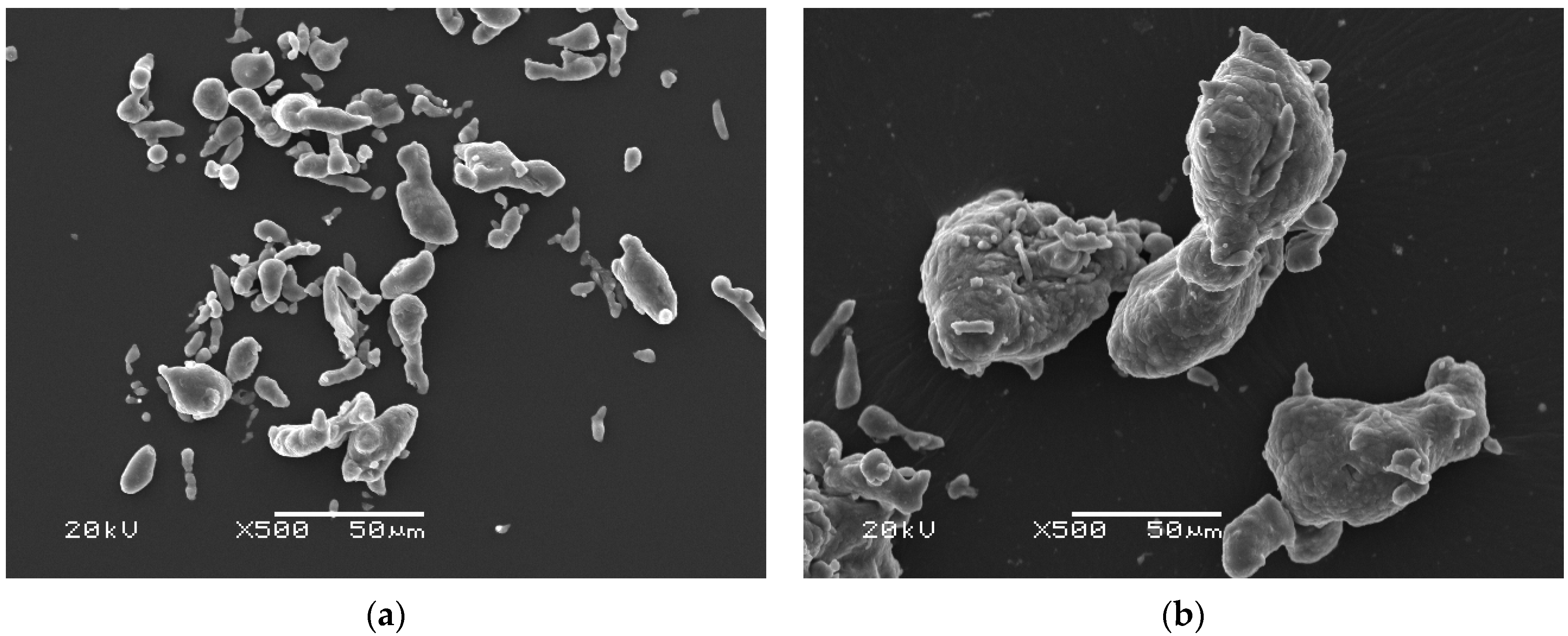
Atomized in an inert gas atmosphere, irregular aluminum powder with CAS number 7429-90-5 (SELKAT, Cracow, Poland) with a purity of 99.7% was used for sample preparation by Binder Jetting technology. The elemental composition of Al powders is shown in 
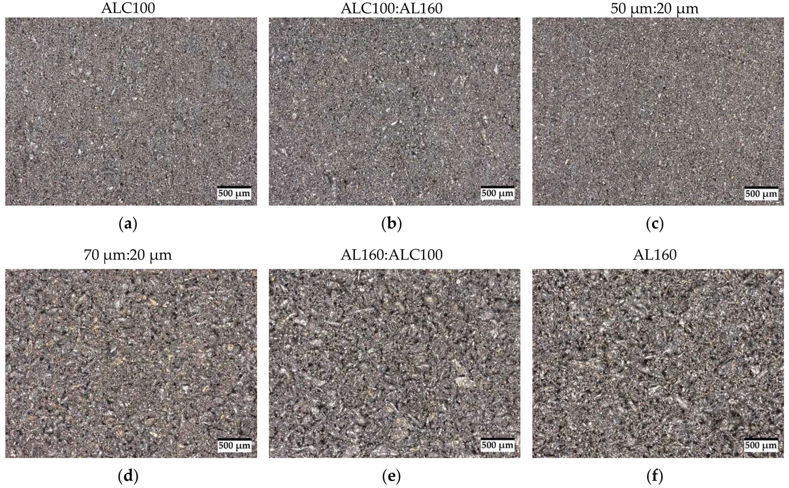
Table 1. Powders in the delivery state, non-sieved (ALC100 and AL160), with mean particle sizes of about 20 µm and 55 µm, respectively, were used (Figure 1). It was observed that the surface of aluminum powders was rough and irregular with the presence of an oxide layer.
The binding material of the powder was a solvent-type Aqueous Binder (BA005) from ExOne (The ExOne Company, North Huntingdon Township, PA, USA) with a pH of 3.5–5.5. The composition of the binder is ethynediol (CAS No.: 107-21-1) and 2-butoxyethanol (CAS No.: 111-76-2) contained in amounts from 2 to 20%.
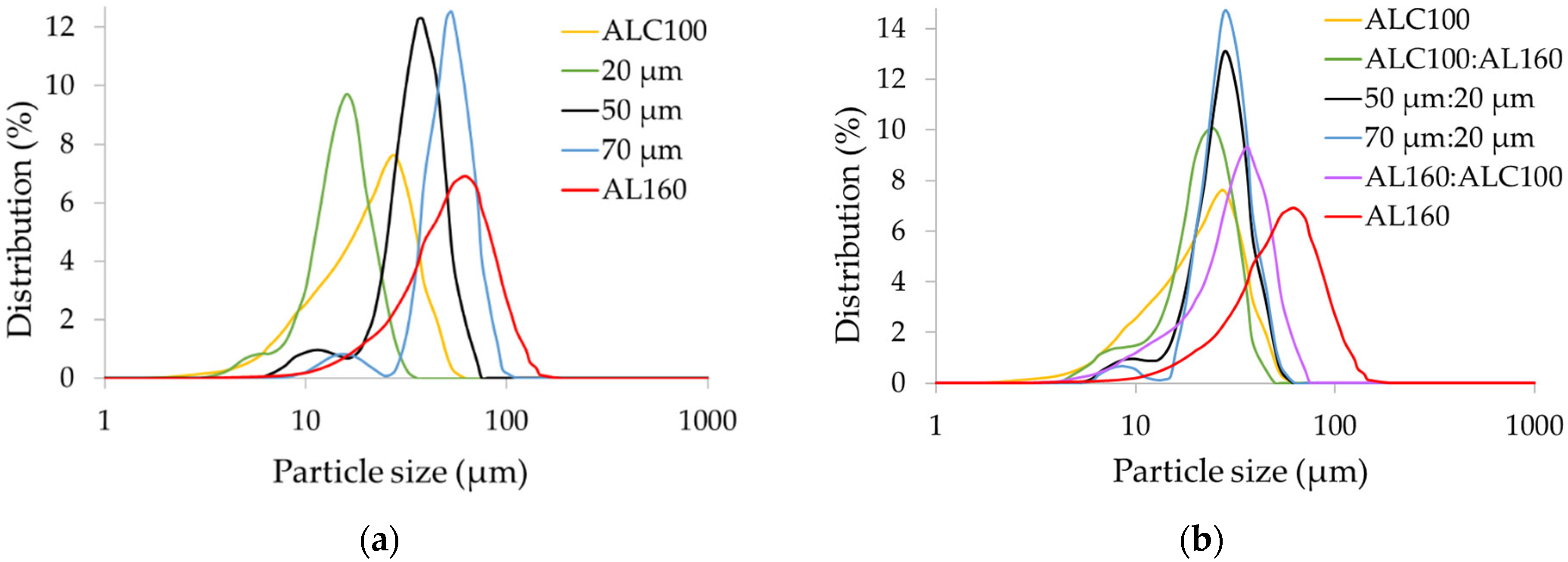
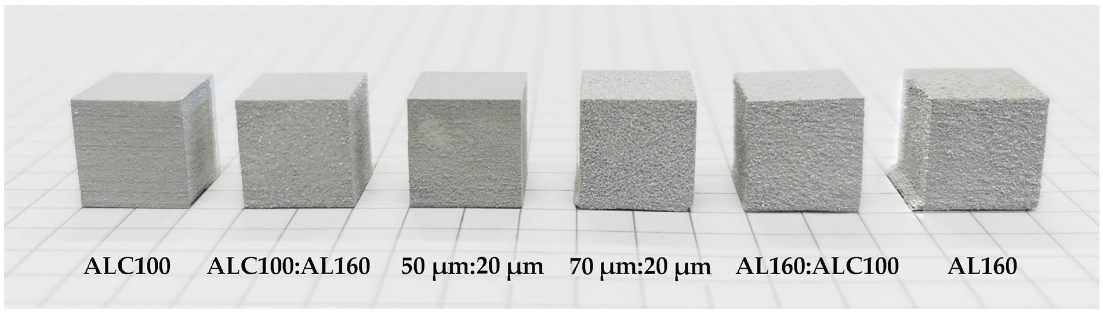
Samples were prepared from powders as supplied (ALC100 and AL160) and from powder blends of different fractions. The aluminum powder was sieved using a laboratory-shaker-type LPzE-2e Ø200 mm (MULTISERW-Morek, Marcyporęba, Poland), and fractions from 80 µm, 75 µm, 63 µm, 50 µm, 45 µm, 40 µm, and <40 µm sieves were separated. Fractions of 75 µm, 50 µm, and <40 µm (based on D90 from the particle size distribution results, designed as 70 µm, 50 µm, and 20 µm, respectively) were selected for the preparation of the blends, due to their different particle sizes with the largest volume share at the same time. The powders were blended under dry conditions in a TURBULA® shaker-mixer model T2F for 16 h. Three blends were prepared by blending the coarse powder with fine powder in a weight ratio of 73:27 and one in a weight ratio of 27:73. The composition of individual blends is presented in Table 2.

2.2. Parts’ Fabrication

The parts were printed on an Innovent+® 3D printer (The ExOne Company, North Huntingdon Township, PA, USA) operating with Binder Jetting technology with a working area of 160 mm × 65 mm × 65 mm. A CAD model in the shape of a cube with a side of 10 mm was prepared. The parts were built up layer by layer in the XY plane along the Z direction. Fixed values of binder saturation (80%) and roller traverse speed (10 mm/s) were used for printing, which was selected as optimized in the research for the previous work [48]. To reliably compare the results, a constant layer thickness of 120 µm was used for all variants. The layer thickness was determined based on previously conducted print tests on AL160 powder at layer thicknesses of 60 µm, 120 µm, 150 µm, 180 µm, 200 µm, and 240 µm (Figure S1). The analysis showed that using a layer thickness of 120 µm eliminates the shifting of unanchored layers during printing. Moreover, among the layer thicknesses used, 120 µm gives the highest density and the lowest porosity of the part after the sintering process (Figure S2). In general, the layer thickness should be greater than the maximum size of the printed particles [6]. In the literature, authors usually recommend doubling the thickness of the average particle diameter [62,63]. The decision to use a layer thickness of 120 µm coincides with the above suggestion since the mean particle size of AL160 powder is 55 µm. This layer thickness allowed for maintaining the stability of the layers and the designed shape of the part. The parts were printed with the rest of the same fixed parameters as recoat speed—150 mm/s, roller speed—300 rpm, binder set time—2 s, drying time—15 s, and bed temperature—50 °C.
Immediately after the 3D printing process, the samples were cured in a dryer (BINDER FD 56, Tuttlingen, Germany) at 200 °C for 4 h. The annealing process serves to remove volatile binding solvents [64]. After this step, it was possible to effectively separate the printed brown parts from the surrounding powder. The samples were then sintered in a horizontal tube furnace (Nabertherm RHTH 120-600/17, Lilienthal, Germany). The parts were sintered under vacuum according to the following temperature profile: heating at a rate of 1 °C/min to 300 °C, then 450 °C and 620 °C and holding for 1 h each time. The parts along with the furnace were cooled to room temperature.

2.3. Characterization Methods

The chemical composition was analyzed using an EDX-7200 Energy-Dispersive X-ray Fluorescence Spectrometer (Shimadzu Europa GmbH, Duisburg, Germany) in an air atmosphere.
Characterization of the particle size distribution of powder blends was performed by the wet method using an Anton-Paar PSA 1190LD laser particle size analyzer (Anton-Paar, Graz, Austria). The volume-size distribution was expressed as D10, D50, and D90.
The morphology of the powder particles was analyzed using a scanning electron microscope (JEOL JSM5510LV, JEOL, Tokyo, Japan) at an accelerating voltage of 20 kV.
The specific surface area was measured using the Quantachrome Autosorb iQ-MP physical sorption analyzer (Anton Paar, Graz, Austria). The powder degassing process was carried out in three steps: (1) heating from ambient temperature to the degassing temperature of 80 °C at a rate of 2 °C/min with a soaking time of 30 min; (2) heating to 120 °C at a rate of 2 °C/min and soaking for 30 min; (3) heating to the degassing temperature of 350 °C at a rate of 5 °C/min and soaking time of 400 min. Specific surface area measurements were determined using the Brunauer–Emmett–Teller (BET) method. The results were analyzed using Quantachrome ASiQwin software (version 5.21).
The phase composition of the samples was determined by X-ray diffraction (XRD). Diffraction patterns were recorded on an Aeris apparatus (Malvern Panalytical) using CuKα1 radiation (λ = 1.540598 Å). The samples were scanned over an angular range of 30° to 100° (2θ) with a step size of 0.003° (2θ) and a time per step of 340 s. Qualitative analysis was carried out using HighScore Plus software (version: 4.8, Malvern Panalytical B.V., Almelo, The Netherlands) based on data in the PDF-4+ catalog of the International Centre for Diffraction Data (ICDD).
Samples were weighed on a PS 1000.X2 precision balance (RADWAG Wagi Elektroniczne, Radom, Poland), and dimensions were measured with a digital caliper both to determine dimensional changes in the X, Y, and Z axes and to calculate geometric density. The dimensions of the parts after annealing were compared with those of the designed CAD model (10 mm × 10 mm × 10 mm). The samples were then weighed and measured after the sintering process. The linear shrinkage of the samples after the sintering process was calculated according to Equation (1), where L is the linear shrinkage, l1 is the original side length, and l2 is the side length after heat treatment [65]:
L   ( % ) = l 1 l 2 l 1 × 100
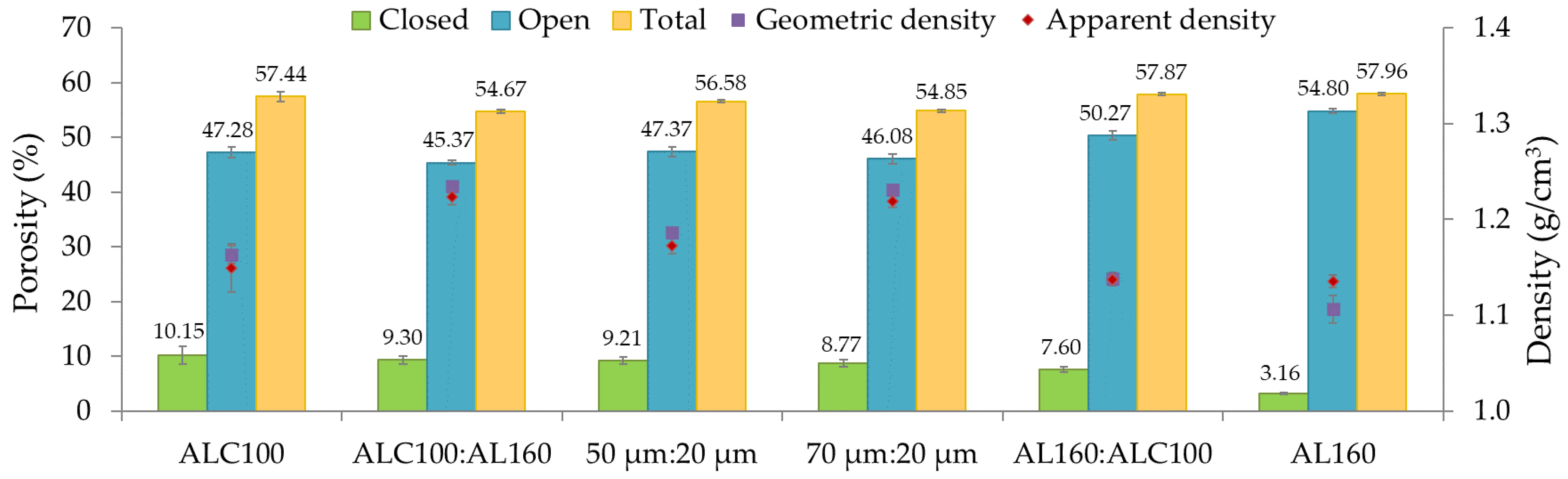
Geometric density was calculated as the ratio of mass to volume of the part. Relative density was determined as the ratio of the apparent density of the sample to the theoretical density (ρt) of aluminum (2.7 g/cm3) and expressed as a percentage.
The apparent density and apparent porosity of the parts were determined in accordance with the ASTM 373 standard based on Archimedes’ principle. Water with a density of 0.99 g/cm3 (at 20 °C) was used as the immersion medium. The dry mass of the sample (m1) was determined. Subsequently, the sample was immersed in water and its mass in immersion (m2) was measured. Next, the sample was removed from the water and the mass of the wet sample in the air (m3) was determined [65]. The weighing was performed on a RADWAG balance with an accuracy of 0.001 g. The result was estimated from three repetitions of the measurement.
The apparent density (ρ) was calculated according to Equation (2), where ρw is the density of water:
ρ   ( g c m 3 ) = m 1 m 3 m 2 × ρ w
The open porosity (OP) was determined according to Equation (3):
O P   ( % ) = m 3 m 1 m 3 m 2 × 100
The total porosity (TP) was determined according to Equation (4), where ρ is the apparent density:
T P   ( % ) = ρ t ρ ρ t × 100
The closed porosity (CP), which is the difference between total porosity and open porosity, was calculated according to Equation (5):
C P   ( % ) = T P O P
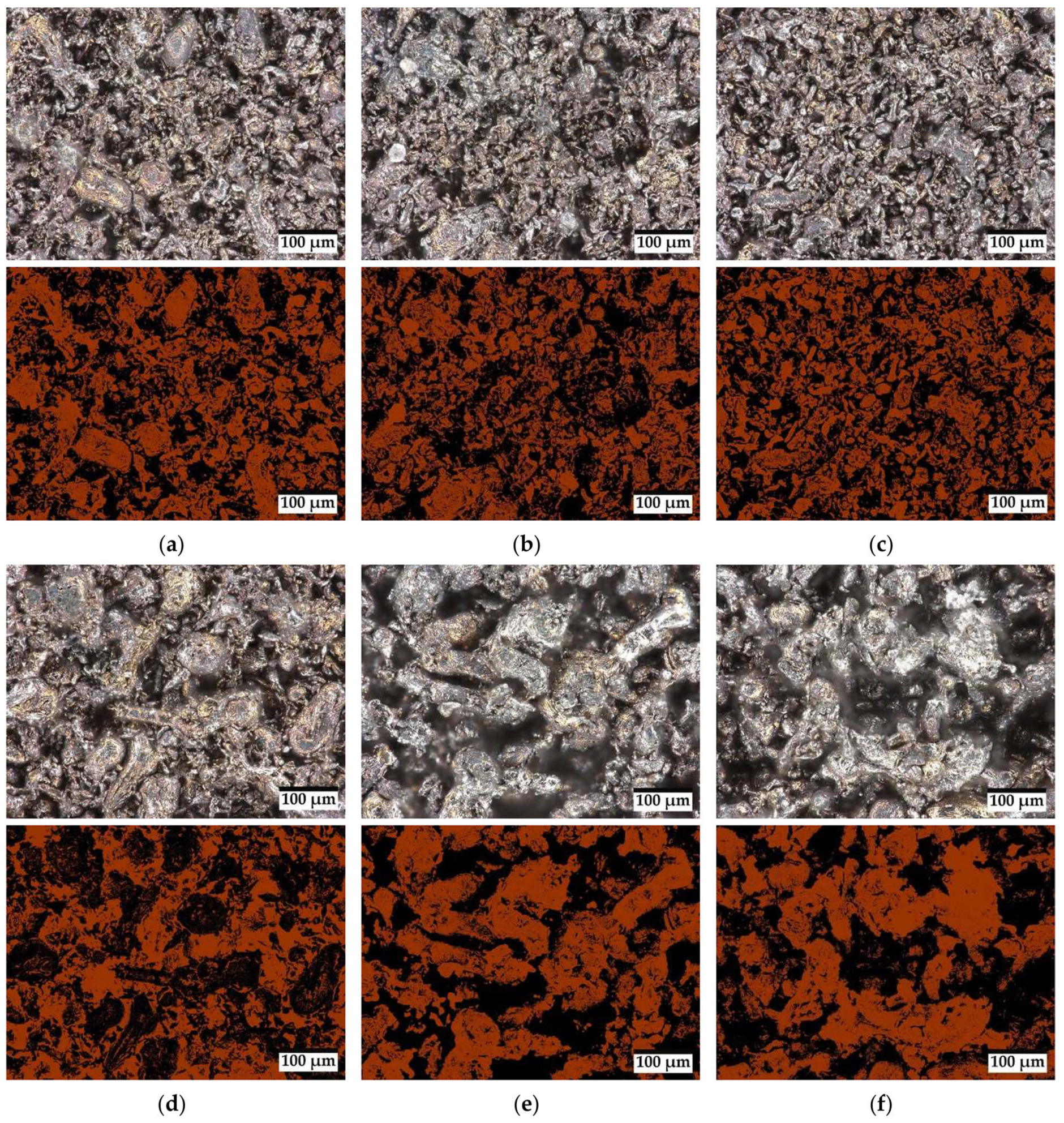
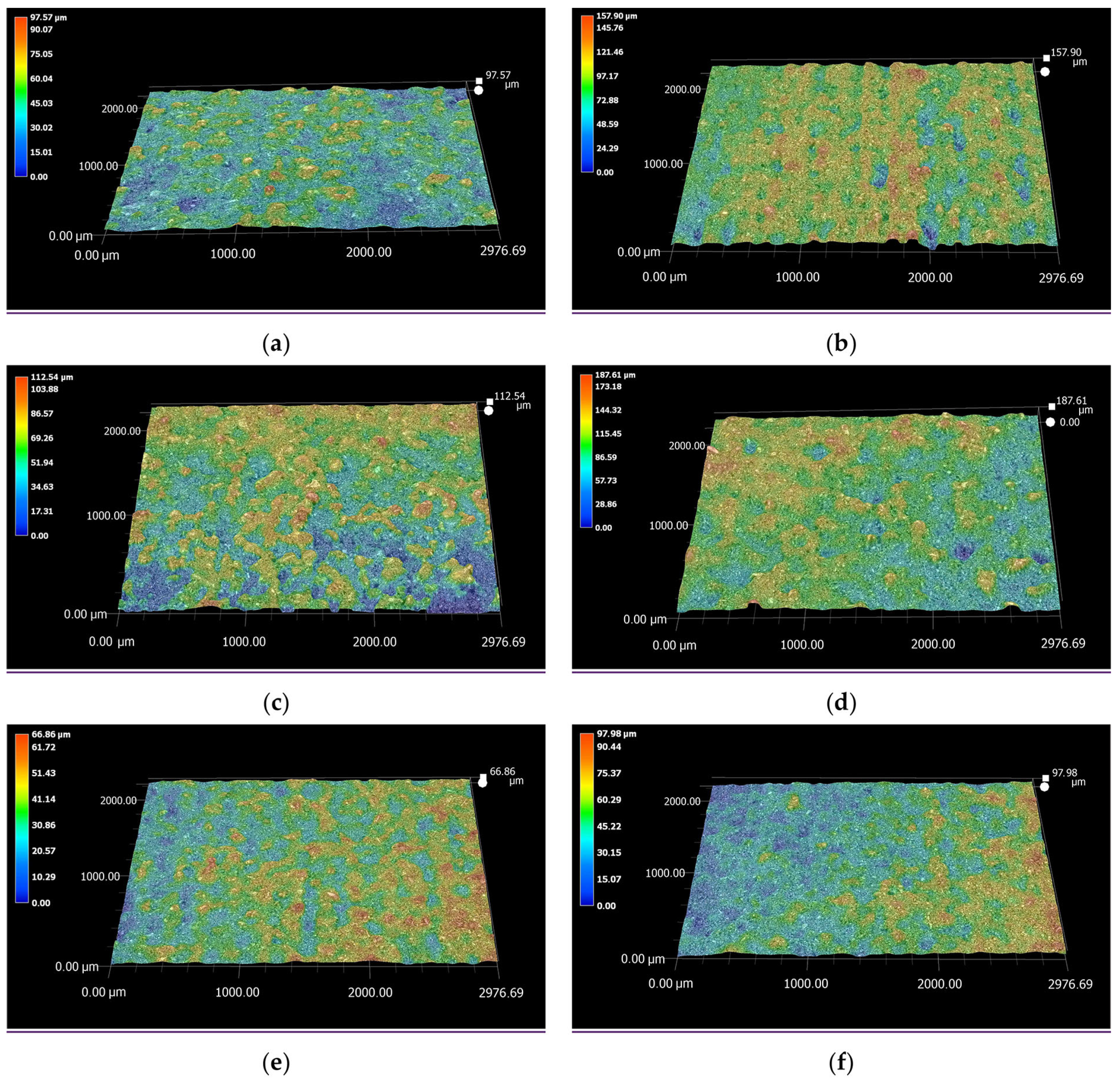
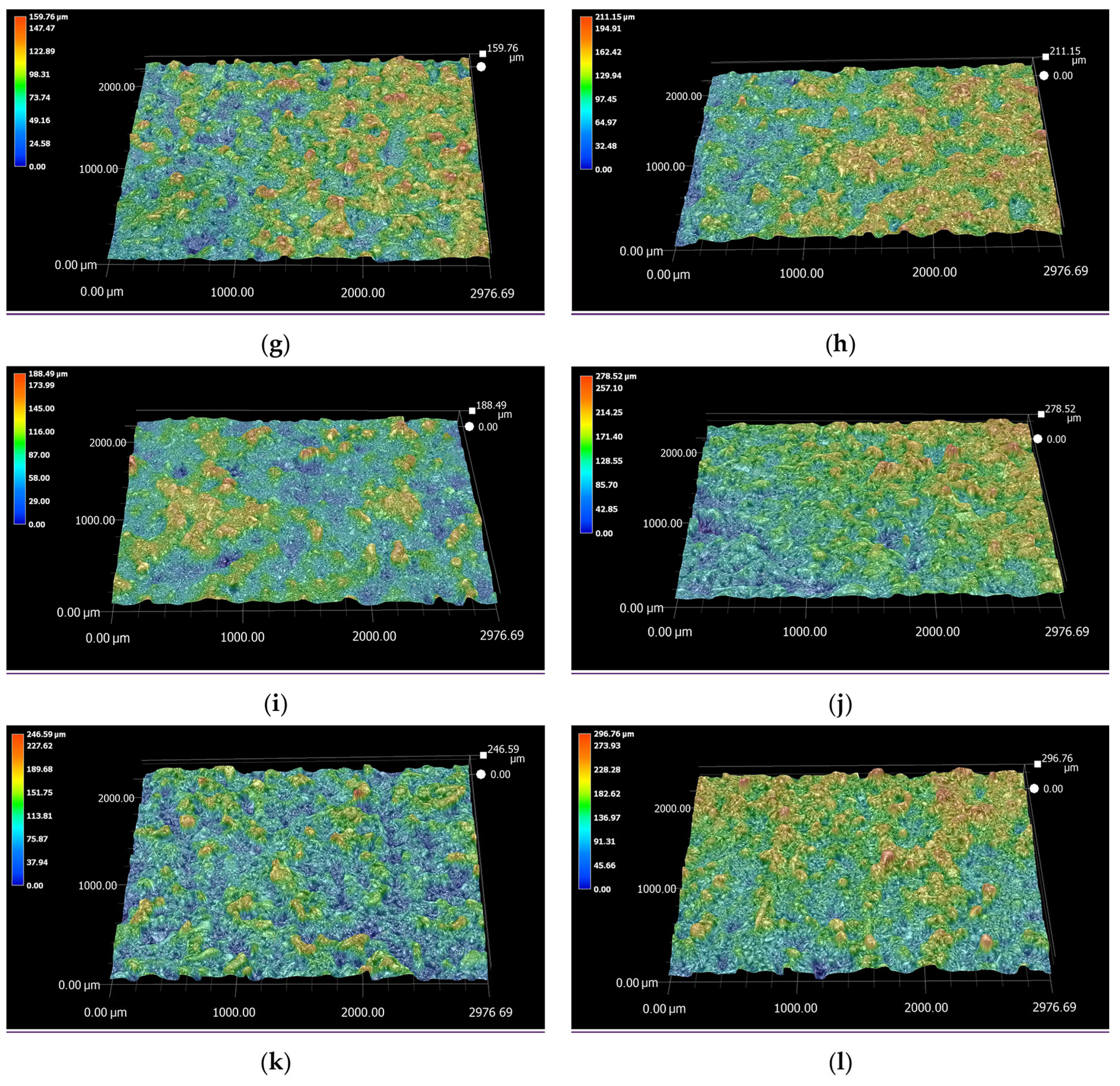
The surface images of the samples, the porosity, and the surface roughness of the cubes were determined using a digital microscope (Keyence VHX-7000, KEYENCE International, Mechelen, Belgium). Porosity was determined from images taken on the surface of the sample. Topographic images were taken on the area of 2.98 × 2.00 mm2 area. Various works reported in the literature also assumed similar area dimensions, for example: 2.5 × 3.0 mm2 by Koutiri et al. [66], 2.9 × 2.9 mm2 by Thompson et al. [67], and 2.0 × 2.0 mm2 by Zhu et al. [
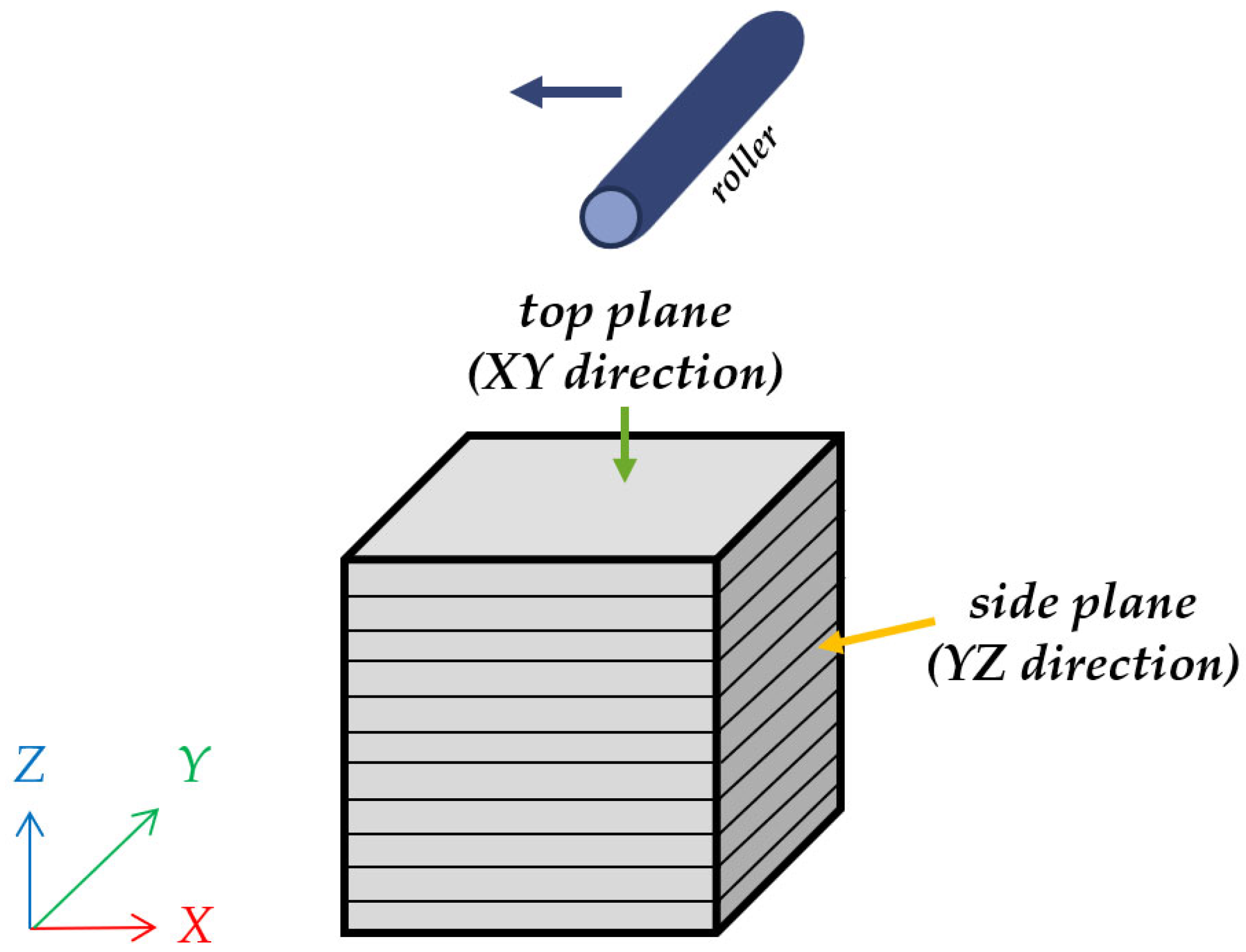
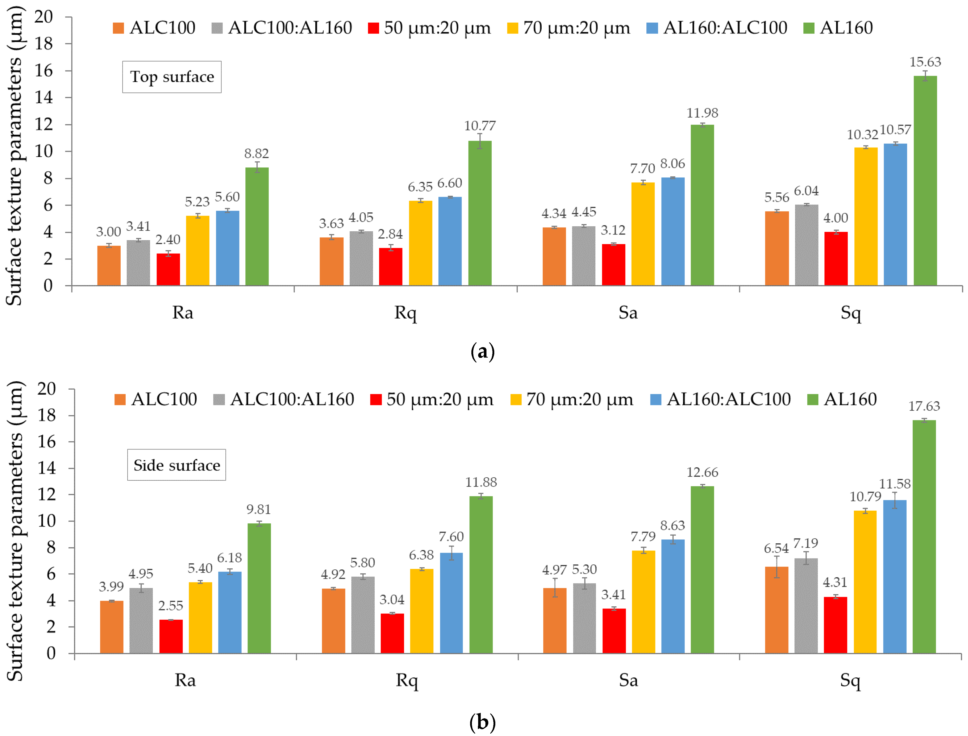
68]. Roughness measurements were made on two surfaces with different orientations in relation to the 3D printing direction, on the surface parallel to the direction of travel of the rotation roller (XY plane) and along the side surface (YZ plane). A schematic of the tested surfaces is shown in Figure 2.
A Gaussian filter was used to test the roughness. The cut-off wavelength λc corresponded to 0.25 mm and was selected according to ISO 3274:1996 [69]. The tests were conducted on a 1.0 × 1.0 mm2 surface. Three measurements were taken for each surface tested, from which the average was then determined. Surface roughness (for lines) was evaluated using the Ra parameter (arithmetic average height, µm) and Rq parameter (root-mean-square roughness, µm) according to ISO 4287 [70]. Selected surface roughness parameters (for the area) were determined with reference to ISO 25178, which defines the parameters for determining the surface texture, such as Sa (area-average roughness, µm), Sq (area-root-mean-squared height, µm), Ssk (area height distribution skewness), and Sku (area height distribution kurtosis) [71,72]. The parameters Ssk and Sku are recommended for characterizing surfaces produced by additive manufacturing [68].

3. Results and Discussion

3.1. Powder Particle Size Distribution

The results of the particle size distribution analysis of individual fractions and blends of powders are shown in Figure 3 and Table 3.
The results of the particle size distribution of aluminum powder showed that AL160 powder has 2.5-fold the mean particle size of ALC100 powder. Analyses were also carried out for blends with different particle sizes and a share of 73–27 wt.%. The ratio was selected based on an analysis of the literature and the results of experiments conducted by Bai et al. [56,57] and Kumar et al. [73]. Experiments have shown that a high packing density can be obtained when the volume fraction of fine powder is between 0.2 and 0.4 [57]. Using bimodal powder blends can improve the powder packing density. Fine particles that fill in the spaces between large particles form powder blends to increase the density of green parts and reduce shrinkage after sintering. The addition of larger powders to a fine-grained skeleton can improve the packing density, but densification can be hindered due to the difficulty of sintering large powder particles [56]. As noted by Bai et al. [57], a 73–27 wt.% (73% coarse powder) mixture of 75 µm + 15 µm powder introduces large particles into the blend and improves the powder bed density by 16.2% compared to the 15 µm powder. The production of AL160:ALC100 compositions in the proportion of 73–27 wt.% made it possible to obtain a blend with a mean particle size of 32.06 μm. In contrast, combining the powders in opposite proportions (ALC100:AL160, 73–27 wt.%) did not contribute to obtaining a blend with a significantly different particle size distribution than for the ALC100 powder. However, it can be expected that a greater variation in particle size may contribute to better powder packing. The preparation of the 50 µm:20 µm and 70 µm:20 µm blends (in a 73–27 wt.% share) yielded powders with a mean particle size of 27.77 µm and 29.23 µm, respectively. Powders of large particle diameter, compared to fine powders, are characterized by better flowability but worse sinterability. Particles below 20 µm usually have a large specific surface area, which means that they have a higher energy state and, as a result, lead to more efficient sintering and higher density [30]. Similarly, Moghadasi et al. [74] in their work found that the use of smaller powder particles for BJ printing increases the strength of sintered parts. This is influenced by the high sinterability that is characteristic of fine powders.

3.2. Specific Surface Area

Figure S3 shows the N2 adsorption–desorption isotherms of aluminum powders. The obtained isotherms according to the IUPAC classification can be referred to as type IV isotherms. They are characterized by the presence of an hysteresis loop (type H3), which is attributed to the filling (adsorption)/vacating (desorption) of mesopores with gas by capillary condensation [75]. Table 4 shows the results of the specific surface area determined based on the BET procedure for various blends of aluminum powder.
Generally, the specific surface area (BET) of aluminum powder should be in the range of 0.4 to 0.8 m2/g [76]. The results obtained for the analyzed aluminum powders fall within this range. The materials are characterized by a specific surface area in the range of 0.405 m2/g to 0.545 m2/g. The value of the specific surface area is negatively correlated with the size of the powder particles. Gao et al. [77] tested high-purity aluminum powders in their study. They observed that the specific surface area of aluminum powders with a size of 150–280 µm (0.435 m2/g) is lower than for powders with a size of 4.5–7 µm and 25 µm (0.626 m2/g and 0.644 m2/g, respectively).
Significantly from the point of view of powder distribution, the finer the powder, the larger the powder’s surface area. This increases the friction force between the particles and the binder, which increases the binder distribution time [6].

3.3. Visual Characterization

Figure 4 shows the printed parts depending on the particle size compositions used for printing. For all samples, the printing parameters were constant: saturation of 80%, roller traverse speed of 10 mm/s, and layer thickness of 120 µm, to compare the effect of particle size on print quality without considering other variables. Based on the obtained results, it was found that 3D printing from powders with large particles causes part deformation, which can be observed by the shifting of unanchored layers during powder coating. Layer thickness also affects the properties of the final parts, as confirmed by the results shown in Figure S2 and in the previous work [48]. Gonzalez et al. [78] showed that using a smaller layer thickness and large size distribution of the printed powder contributes to a higher part density. Therefore, as part of our research, to eliminate the deformation that occurs during powder application at a layer thickness of 60 µm (Figure S1), it was necessary to increase the thickness to 120 µm. To reliably compare the effect of particle size on the properties of the samples, a constant layer thickness of 120 µm was used for all variants.
Based on microscopic images of the sample surfaces taken at 100× magnification (Figure 5), it can be observed that blends of finer powders (ALC100, ALC100:AL160, and 50 µm:20 µm) give a smoother surface after the 3D printing process. Of these three variants, the surface of samples prepared with 27 wt.% of AL160 powder (55 µm) has greater surface irregularities since the presence of larger particles contributes to an inconsistent deposition in the powder bed. In contrast, when powder with a mean size greater than 50 µm was used in the blend at 73 wt.%, a noticeably rougher surface of the 70 µm:20 µm, AL160:ALC100, and AL160 parts was obtained.

3.4. X-ray Diffraction

Figure S4 shows the diffraction patterns obtained for aluminum powders (Figure S4a) and for samples after 3D printing and sintering (Figure S4b). A qualitative analysis was carried out, based on which the aluminum phase was matched to the diffraction peaks. The presence of other phases in the tested materials was not detected. Diffraction effects were identified at the following angular positions: 38.46°, 44.71°, 65.07°, 78.20°, 82.40°, and 99.04° (2θ). Based on the XRD patterns obtained, card no. 04-012-7848 from the ICDD database was matched. X-ray reflections were detected for the (1 1 1), (2 0 0), (2 2 0), (3 1 1), (2 2 2), and (4 0 0) planes. Miller indices indicated the crystal structure of FCC [79]. The lattice parameter of the pure Al FCC structure was 4.051 Å, the Al density calculated from XRD analysis was 2.696 g/cm3, and the space group was Fm-3m.

3.5. Relative Density

Figure 6 shows the relative density results obtained for brown and sintered parts of each investigated variant of samples. The density was calculated based on the apparent density determined by the Archimedes method. The results confirm that the sintering process increased the density of the parts. The density of the samples after heat treatment increased by about 1–2%. A significantly higher increase in density after sintering was observed for parts made of AL160 powder, characterized by particles with a mean size of 55 µm. The highest density was recorded for samples made from powder blends of 73–27 wt.% with ALC100:AL160 and 70 µm:20 µm designations. The lowest relative density was obtained for AL160 samples.
Thus, both ALC100:AL160 and 70 µm:20 µm blends produced satisfactory results. In contrast, Bai et al. [56,57] in their work observed that the use of a mixture of 5 + 15 µm or 5 + 30 µm powders at a proportion of 73–27 wt.% resulted in an increase in density concerning a fine powder. Moreover, the 75 + 15 µm blend (73–27 wt.%) allowed for obtaining the highest density of the powder bed among all the blends tested. However, for an effective enhancement in density, mixtures with a predominance of fine particles are best suited. The authors noted that there is a tendency for necking to form between 75 µm and 15 µm particles. Large particles form a skeleton and inhibit the sintering process. However, the researchers used spherical copper powders for the study. Therefore, it should be noted that the powder morphology varies when using bimodal powder blends for 3D printing. Bimodal powder blends can have a positive effect on powder packing density. Finer powders can fill intermolecular pores, resulting in an increased part density. This often translates into higher mechanical properties after densification [6]. Comparing the results obtained for the powders in the as-delivered state (ALC100 and AL160) and the bimodal blends formed from them at 73–27 wt.% (ALC100:AL160 and AL160:ALC100), it can be seen that the addition of 27% fine powder to coarse powder resulted in a considerable increase in the density of the brown parts. However, after sintering, both materials achieved almost identical densities. On the other hand, the introduction of 27% coarse powder to fine powder contributed to a significant increase in brown density and density after sintering.

3.6. Dimensional Changes

Figure 7a shows the results of the dimensional changes of the brown parts concerning the nominal dimensions of the CAD-designed model. In general, the dimensions of the samples after the printing process were slightly higher than 10 mm, which is due to the need to introduce a binder. The results confirm that as the particle size increased, an increasing trend was observed regarding the dimensional changes in the X, Y, and Z axes after 3D printing. In general, for parts formed from fine powders (ALC100, ALC100:AL160, and 50 µm:20 µm), the value of dimensional changes did not increase above 3% concerning nominal dimensions. For coarser powders (70 µm:20 µm, AL160:ALC100, and AL160), the dimensional changes were already at the level of 2.6–7.6%. In general, for most variants, the dimensional changes along the X and Y directions were very similar. The largest dimensional changes occurred in the Z axis. This may be due to the effect typical of additive manufacturing, consisting of the addition of powder to the Z dimension through the penetration of the binder into the dry powder bed [80].
Figure 7b shows the dimensional changes that occurred for individual parts in the X, Y, and Z axes after the sintering process. To calculate shrinkage, the dimensions of the brown parts were used as a reference. During this stage, part densification (shrinkage) occurs, which can be compensated by increasing the dimensions of the printed parts accordingly. The degree of shrinkage was closely dependent on the starting powder used [81].
For the tested variants of powder blends, the results were analogous to the results obtained for the samples after printing. After the sintering process, greater shrinkage was recorded for those samples for which there was also a greater increase in dimensions after printing. As the particle size of the powder from which the parts were made increased, the sintering shrinkage increased. For ALC100, ALC100:AL160, 50 µm:20 µm, 70 µm:20 µm, and AL160:ALC100 powders, the shrinkage practically did not exceed 2%. On the other hand, shrinkage up to about 3% was recorded for AL160 powder. For most variants, the greatest shrinkage was noted in the Z-axis. A similar relationship was also observed by Cai et al. [22]. The shrinkage in the Z-axis may be greater than in the X and Y directions because, according to Jamalkhani et al. [82], during the binder jetting process, subsurface porosity can form in the layers through droplets. In the burning process, the binder may decompose, and as a result, interlayer gaps will be formed, which will be filled by the upper layers moving downward, resulting in shrinkage in the Z-axis [83,84]. Shrinkage in the build direction can also be caused by a temporary change in density as a result of defects occurring during powder application [28].
In general, most parts produced by Binder Jetting were characterized by sintering shrinkage. Powders with higher packing density can contribute to the reduction in this phenomenon [57]. Powder blends consisting of both fine and coarse particles increased the packing density of the powder bed. As can be seen in Figure 7b, parts made from the ALC100:AL160 powder blend (73–27 wt.%) had relatively low shrinkage after sintering and, at the same time, the highest density, which confirms the above theory.
Figure 7c shows the dimensional changes after sintering, for which the nominal dimensions of the CAD model were used as a reference. As mentioned earlier, after printing the Al samples, dimensional growth occurred, while sintering resulted in shrinkage. However, by relating the final dimension values to the dimensions determined at design, it can be seen that parts made from finer powders were still characterized by shrinkage at a level not exceeding 1%. On the other hand, for samples made of coarser powders, the larger the particle size, the greater increase in dimensions appears. These results suggest that finer particles sinter better than coarser particles.

3.7. Porosity

Figure 8 presents the results of porosity determined by the Archimedes method. Samples made from different blends of aluminum powders had quite high total porosity, reaching 58%. In general, green parts printed by Binder Jetting often have porosities in the range of 45–65% and densities lower than parts produced by powder metallurgy [85]. No pressure is applied in BJ fabrication, resulting in poorer powder packing [80]. In contrast, with traditional methods, just pressing the powder alone yields a relative density of 80% [85].
The closed porosity of the parts shown in Figure 8 was in the range of 3–10%. As the particle size increased, its decrease was noted. The highest open porosity was recorded for AL160 and AL160:ALC100 samples, which were 54.80% and 50.27%, respectively. In contrast, the lowest open porosity of 45.37% and 46.08% was observed for ALC100:AL160 and 70 µm:20 µm samples, respectively. Both shape and particle size have a significant effect on open porosity. Non-spherical powders will exhibit a lower packing density than spherical powders. In terms of pore size, the particle size of the powder is important. Smaller powder particles have a higher surface energy and smaller pores, resulting in an earlier and higher part density [86]. Kumar et al. [59] noted that, in the case of bimodal powders, the porosity of the part is lower and evenly distributed in the inner areas of the sample, and the surface porosity is sealed. Literature reports [29] also suggest that carbon residues from binder pyrolysis may contribute to inter-particle porosity because they inhibit densification.
Table 5 shows the results of porosity measurements made by image analysis on an optical microscope. Photos of the surface were taken at ×500 magnification. The digital image was converted to a binary image and porosity measurements were performed. Part porosity was calculated based on the average of five measurements. Representative examples of the output and binary images for each of the blends are shown in Figure 9.
The results of the porosity estimation based on the binary images presented in Table 5 confirm the repeatability of the results obtained based on measurements using the air and water weighing method. The values obtained from the image analysis were similar to the results of open porosity, which was determined based on the Archimedes method.

3.8. Surface Roughness

Figure 10 shows the results of surface roughness measurements obtained for the top surfaces—XY plane (Figure 10a) and side surfaces—YZ plane (Figure 10b).
Seven standard measures such as (1) arithmetic mean—Sa/Ra; (2) root mean square—Sq/Rq; (3) maximum peak to the valley—Sz/Rz; (4) maximum peak height—Sp/Rp; (5) maximum valley depth—Sv/Rv; (6) skewness (Ssk/Rsk); and (7) kurtosis (Sku/Rku) are commonly used to measure surface roughness [71]. In this study, the values of Ra, Rq, Sa, Sq, Ssk, and Sku parameters were determined. Metrics with the letter S (according to ISO 25178) are used for the quantitative characterization of surface roughness. On the other hand, profile surface roughness measurement is denoted by the letter R according to ISO 13565-1. However, research indicates that R parameters are not sufficient to characterize parts produced by additive manufacturing. Profile measurement refers only to individual lines of the roughness profile, so some features may be omitted. Surface measurements measure an area on a surface so they can be more representative [71]. For this reason, the values obtained for the R and S metrics are different, but in general, the trend is maintained for all parameters—Ra, Rq, Sa, and Sq.
The results of the roughness measurements confirmed that the surfaces obtained by distributing the powder through a roller (XY plane) were smoother than the vertical surfaces with built-up layers (YZ plane). Also, Rodríguez-Gonzalez et al. [3] in their work noted that the roughness on the top surface of the 3D-printed parts is lower than on the side surfaces. Figure 10 confirms that for the top planes, surface texture parameter values were up to about 15% lower than those for the side surfaces. Comparing the results for the six variants of powder blends, parts made of fine powders (ALC100, ALC100:AL160, 50 µm:20 µm) show a lower roughness than samples made of 70 µm:20 µm, AL160:ALC100, and AL160 powders. In general, as the mean particle size of the powder increases, the surface roughness of the part increases. The sample made of the 50 µm:20 µm blend, for which the lowest surface roughness was recorded, deviates from this trend. This is probably due to a very good match between particles of two different sizes. The 50 µm particles occupy 73 wt.%. The fine particles (20 µm) fill in the voids and thus provide a smoother surface compared to parts produced from the unsifted ALC100 base powder.
The size of the powder particles used for 3D printing has a significant influence on the surface finish. Finer powder particles should yield smoother surfaces after 3D printing compared to coarser powders. However, the strong forces of attraction (van der Waals) between them reduce the flowability of the powder, which can result in difficult spreading [6,30].
According to Mostafaei et al. [6], the average roughness of sintered parts produced by the Binder Jetting method oscillates around 6 µm (Ra). Comparing the values of the Ra parameter obtained from roughness measurements on the two printed surfaces, it can be seen that samples made from fine powder particles obtained even lower Ra values, ranging from 2.40 µm to 3.41 µm on the top surface and from 2.55 µm to 4.95 µm on the side surface. Blends of 70 µm:20 µm and AL160:ALC100 result in parts with very similar surface quality, 5.23 µm and 5.60 µm for the top surface and 5.40 µm and 6.18 µm for the side surface, respectively. The use of AL160 powder with a mean particle size of 55 µm for 3D printing resulted in a 1.5-fold increase in Ra values (compared to powders with a mean size of about 30 µm). The Ra parameter was 8.82 µm on the top surface and 9.81 µm on the side surface. The higher surface roughness may be a contributing factor to the pores observed between the applied layers [87]. This can be confirmed by the results presented in Figure 8. Parts with higher recorded surface roughness also had higher porosity.
Figure 11 presents the representative topographies of the top and side surfaces of samples manufactured by Binder Jetting technology.
Table 6 lists surface texture parameters such as skewness (Ssk) and kurtosis (Sku) obtained for the top and side surfaces of the parts.
The parameters Ssk and Sku are used to describe the height or depth distribution of peaks and valleys. Skewness (Ssk) indicates the degree of deviation of the rough shape. When Ssk = 0, it indicates a symmetrical distribution of peak and valley heights around the mean plane; Ssk < 0 indicates a distribution of heights above the mean plane; and Ssk > 0 below the mean plane. On the other hand, kurtosis (Sku) is a measure of the sharpness of the roughness profile. When Sku = 3, it indicates a normal height distribution, where indented and sharp areas occur simultaneously; when Sku < 3, the height distribution occurs above the mean plane; when Sku > 3, there is a pointed height distribution [88].
For all analyzed surfaces, the value of Ssk was greater than 0, which means that the surface is dominated by peaks rather than valleys [68]. The Sku parameter for all samples is greater than 3, which means that most valleys and peaks are sharp [68].

4. Discussion on the Prospects of Using Binder Jetting Technology for the Production of Components for Electronic Applications

In recent years, modern technologies have gained high interest from consumers, which is inevitably also related to the need to dynamize the electronics industry. Traditional component manufacturing processes are cost- and time-intensive due to the need for step production and the finishing stage. Additive manufacturing, compared to conventional manufacturing processes, not only produces a target component with a complex shape and high accuracy in a single step but also improves overall ergonomics. The use of Binder Jetting technology is associated with relatively low costs. This is because the unprinted powder can be entirely used to prepare subsequent printouts. In addition, there are no restrictions on the morphology of the printing powder used. For this reason, this study attempts to prepare parts from irregular Al powder. By replacing the spheroidal powders for 3D printing with irregular powder, the cost of the material can be significantly reduced. The Binder Jetting technology allows for the printing of parts with complex geometries, which means it can work well for producing extremely precise parts for electronic applications. In addition, the aluminum used in the present work, as an excellent conductor, provides the potential for producing components for dissipating the heat generated by electronic circuits. An example of such components would be heat sinks. Therefore, an attempt was made to print heat sinks using the Binder Jetting method. The heat sinks were made from aluminum powder, which gave the lowest surface roughness (50 µm:20 µm powder blend). The designed heat sinks with dimensions are shown in Figure 12a, and heat sink printouts are shown in Figure 12b. Figure 12c presents microscopic photos. BJ technology provides the ability to print this type of part in a very short time with good shape reproduction. A possible limitation of the elements produced by the Binder Jetting method may be their porosity, so such elements should not work in an environment of high mechanical loads.

5. Conclusions

The main objective of this study was to evaluate the effect of the particle size of irregular aluminum powder on the properties of Binder Jetting 3D-printed parts. Powders as delivered and blends with a coarse-to-fine particle ratio of 73–27 wt.% or 27–73 wt.% were analyzed. Based on the obtained results, the following conclusions were formulated:
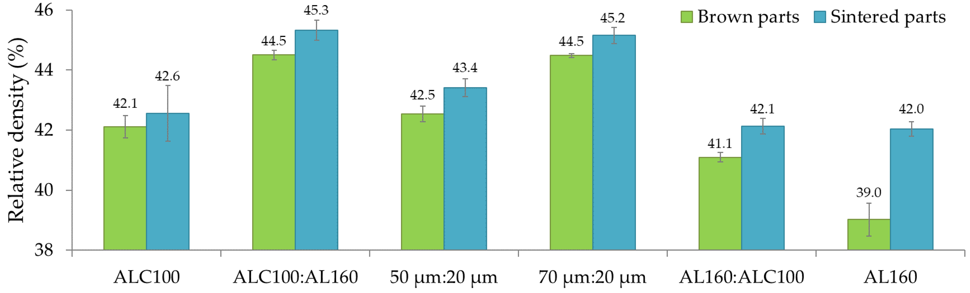
(1) The three-dimensional printing of aluminum powder blends in the Binder Jetting method allowed for relative densities after sintering from 42% to 45% of the theoretical density. This density may be due to the use of irregularly shaped powder particles. As a rule, the spherical shape of the particles promotes better densification. It was observed that parts made from ALC100:AL160 and 70 µm:20 µm powder blends had the highest density. In particular, the incorporation of 27 wt.% of the coarse powder into the base composed of fine powder contributed to significant densification.
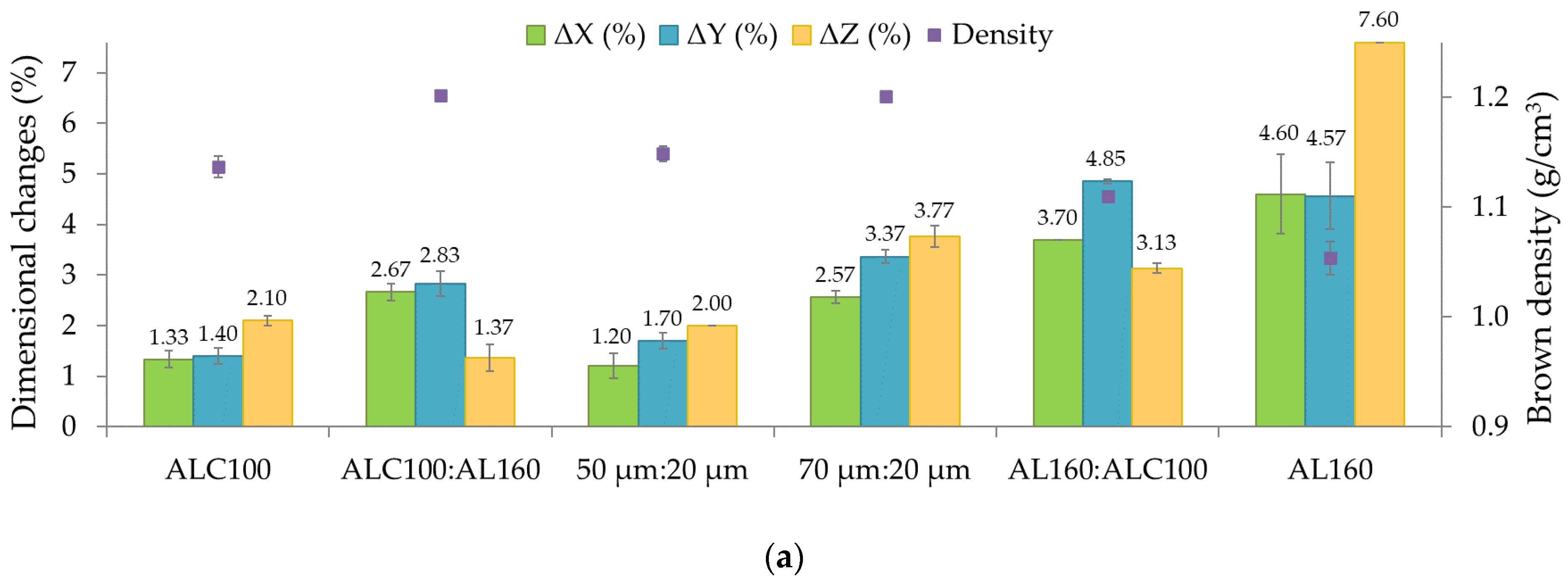
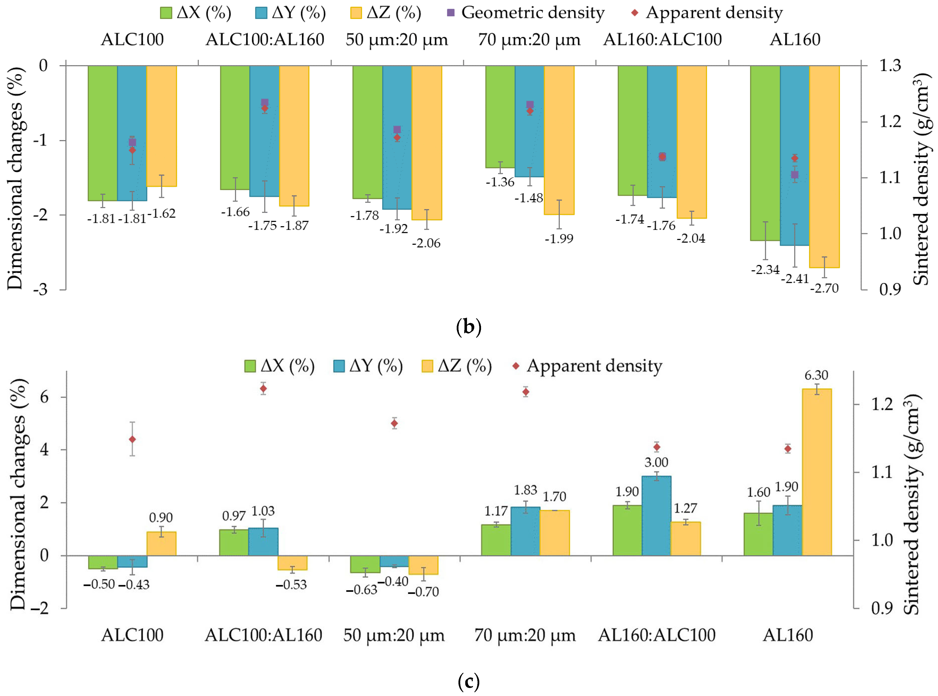
(2) Densification of the printed parts after sintering resulted in shrinkage anisotropy in the X, Y, and Z axes. The largest dimensional changes were observed in the build direction (Z axis). As the mean particle size of the powder blends increased, there was a higher shrinkage after the heat treatment process. Nevertheless, the sintering shrinkage did not exceed 3%.
(3) The printed parts achieved quite a high total porosity, reaching 58%. Pressure is not applied during BJ printing, resulting in inferior powder packing. Powder blends composed of finer powders made it possible to produce parts with a lower total porosity compared to the ALC100 base powder. The use of large powder particles (55 µm) for 3D printing resulted in increased porosity.
(4) The top surfaces (XY plane) of the obtained parts were characterized by up to about 15% lower roughness than the side surfaces (YZ plane). As the mean particle size increased, the values of the roughness parameters increased, excluding the 50 µm:20 µm blend. The combination of these two particle sizes showed a beneficial effect of filling voids with small powder particles, which translated into a reduction in surface roughness. An increase in roughness causes higher part porosity and can promote the formation of interlayer pores. Analysis of the surface topography showed that the surface of the 3D-printed parts was dominated by sharp peaks.
Summarizing the experimental results obtained for all analyzed Al blends, it can be observed that finer powders have a more favorable effect on the final properties of parts printed by Binder Jetting technology. The introduction of large powder particles at 27 wt.% into the fine base caused an increase in density and a decrease in part porosity compared to other Al blends. On the other hand, the addition of fine powder to the coarse particle blend (constituting 73 wt.%) contributed to the reduction in surface roughness. In terms of all the results analyzed, the most promising results were obtained for a blend consisting of 73 wt.% of ALC100 powder and 27 wt.% of AL160 powder.
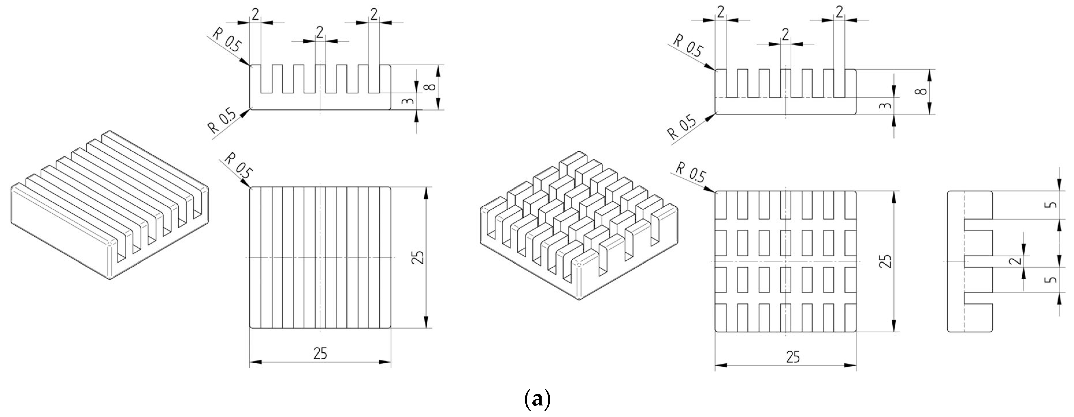
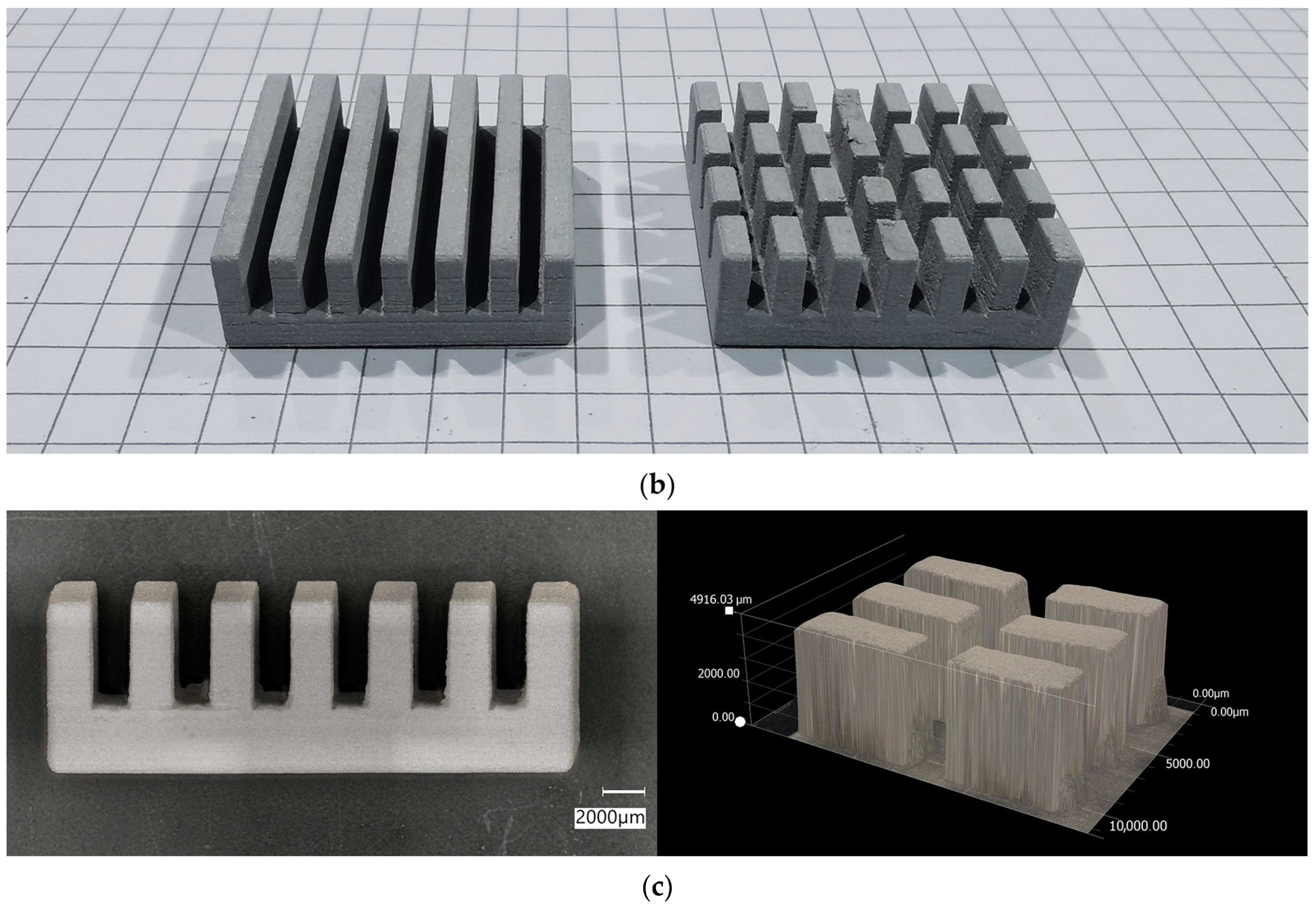
The research carried out in this work has confirmed the possibility of fabricating aluminum parts from powders with varying particle size distributions using Binder Jetting technology. Additive manufacturing methods are an advantage over conventional methods in the case of the possibility of producing constructions with geometrically complex shapes. The promising capabilities of Binder Jetting technology, coupled with a material that acts as a conductor, provide a combination with significant potential for producing 3D-printed parts for electronics applications. Aluminum, through its non-magnetic nature, does not interfere with the sensitive magnets found inside devices. For this reason, it can be used in the branch of computer components, such as transistor housing components or heat sinks, which are dedicated to dissipating the heat generated by electronic circuits.

Supplementary Materials

The following supporting information can be downloaded at: https://www.mdpi.com/article/10.3390/electronics12122733/s1, Figure S1: AL160 parts printed with a variable layer thickness (from the left: 60 µm, 120 µm, 150 µm, 180 µm, 200 µm, and 240 µm); Figure S2: Influence of layer thickness on relative density and porosity of AL160 samples; Figure S3: Nitrogen adsorption-desorption isotherms of aluminum powders: (a) ALC100; (b) ALC100:AL160; (c) 50 µm:20 µm; (d) 70 µm:20 µm; (e) AL160:ALC100; (f) AL160, where (b–e) were made with a share of 73–27 wt.%; Figure S4: XRD patterns for (a) aluminum powders; (b) 3D printed parts with the Binder Jetting method.

Author Contributions

Conceptualization, J.M. and M.H.; methodology, J.M. and M.H.; validation, M.H.; formal analysis, J.M. and M.H.; investigation, J.M.; resources, M.H.; writing—original draft preparation, J.M. and M.H.; writing—review and editing, J.M. and M.H.; visualization, J.M. and M.H.; supervision, M.H.; funding acquisition, M.H. All authors have read and agreed to the published version of the manuscript.

Funding

This research received no external funding.

Data Availability Statement

All dates are included within the manuscript.

Conflicts of Interest

The authors declare no conflict of interest.

References

  1. Calignano, F.; Mercurio, V. An Overview of the Impact of Additive Manufacturing on Supply Chain, Reshoring, and Sustainability. Clean. Logist. Supply Chain 2023, 7, 100103. [Google Scholar] [CrossRef]
  2. Cabezas, L.; Berger, C.; Jiménez-Piqué, E.; Pötschke, J.; Llanes, L. Testing Length-Scale Considerations in Mechanical Characterization of WC-Co Hardmetal Produced via Binder Jetting 3D Printing. Int. J. Refract. Met. Hard Mater. 2023, 111, 106099. [Google Scholar] [CrossRef]
  3. Rodríguez-González, P.; Zapico, P.; Robles-Valero, P.E.; Barreiro, J. Novel Post-Processing Procedure to Enhance Casting Molds Manufactured by Binder Jetting AM. Addit. Manuf. 2022, 59, 103142. [Google Scholar] [CrossRef]
  4. Korniejenko, K.; Łach, M.; Chou, S.Y.; Lin, W.T.; Mikuła, J.; Mierzwiński, D.; Cheng, A.; Hebda, M. A Comparative Study of Mechanical Properties of Fly Ash-Based Geopolymer Made by Casted and 3D Printing Methods. IOP Conf. Ser. Mater. Sci. Eng. 2019, 660, 012005. [Google Scholar] [CrossRef] [Green Version]
  5. Kumari, G.; Pham, T.Q.; Suen, H.; Rahman, T.; Kwon, P.; Foster, S.N.; Boehlert, C.J. Improving the Soft Magnetic Properties of Binder Jet Printed Iron-Silicon Alloy through Boron Addition. Mater. Chem. Phys. 2023, 296, 127181. [Google Scholar] [CrossRef]
  6. Mostafaei, A.; Elliott, A.M.; Barnes, J.E.; Li, F.; Tan, W.; Cramer, C.L.; Nandwana, P.; Chmielus, M. Binder Jet 3D Printing—Process Parameters, Materials, Properties, Modeling, and Challenges. Prog. Mater. Sci. 2021, 119, 100707. [Google Scholar] [CrossRef]
  7. Mirzababaei, S.; Paul, B.K.; Pasebani, S. Microstructure-Property Relationship in Binder Jet Produced and Vacuum Sintered 316 L. Addit. Manuf. 2022, 53, 102720. [Google Scholar] [CrossRef]
  8. Peng, Y.; Unluer, C. Development of Alternative Cementitious Binders for 3D Printing Applications: A Critical Review of Progress, Advantages and Challenges. Compos. Part B Eng. 2023, 252, 110492. [Google Scholar] [CrossRef]
  9. Marczyk, J.; Ziejewska, C.; Gądek, S.; Korniejenko, K.; Łach, M.; Góra, M.; Kurek, I.; Doğan-Sağlamtimur, N.; Hebda, M.; Szechyńska-Hebda, M. Hybrid Materials Based on Fly Ash, Metakaolin, and Cement for 3D Printing. Materials 2021, 14, 6874. [Google Scholar] [CrossRef]
  10. Nyamekye, P.; Rahimpour Golroudbary, S.; Piili, H.; Luukka, P.; Kraslawski, A. Impact of Additive Manufacturing on Titanium Supply Chain: Case of Titanium Alloys in Automotive and Aerospace Industries. Adv. Ind. Manuf. Eng. 2023, 6, 100112. [Google Scholar] [CrossRef]
  11. Massard, Q.; Munoz, J.; Raffestin, M.; Urville, C.; Faverjon, P. Innovative Additive Manufacturing Cutting Tool Design Methodology for Automotive Large Boring Operations Such as E-Motor Housing. Procedia CIRP 2022, 108, 19–24. [Google Scholar] [CrossRef]
  12. Madhavadas, V.; Srivastava, D.; Chadha, U.; Aravind Raj, S.; Sultan, M.T.H.; Shahar, F.S.; Shah, A.U.M. A Review on Metal Additive Manufacturing for Intricately Shaped Aerospace Components. CIRP J. Manuf. Sci. Technol. 2022, 39, 18–36. [Google Scholar] [CrossRef]
  13. Pierre, J.; Iervolino, F.; Farahani, R.D.; Piccirelli, N.; Lévesque, M.; Therriault, D. Material Extrusion Additive Manufacturing of Multifunctional Sandwich Panels with Load-Bearing and Acoustic Capabilities for Aerospace Applications. Addit. Manuf. 2023, 61, 103344. [Google Scholar] [CrossRef]
  14. Marczyk, J.; Ziejewska, C.; Pławecka, K.; Bąk, A.; Łach, M.; Korniejenko, K.; Hager, I.; Mikuła, J.; Lin, W.-T.; Hebda, M. Optimizing the L/S Ratio in Geopolymers for the Production of Large-Size Elements with 3D Printing Technology. Materials. 2022, 15, 3362. [Google Scholar] [CrossRef] [PubMed]
  15. Marczyk, J.; Ziejewska, C.; Korniejenko, K.; Łach, M.; Marzec, W.; Góra, M.; Dziura, P.; Sprince, A.; Szechyńska-Hebda, M.; Hebda, M. Properties of 3D Printed Concrete–Geopolymer Hybrids Reinforced with Aramid Roving. Materials. 2022, 15, 6132. [Google Scholar] [CrossRef] [PubMed]
  16. Haleem, A.; Javaid, M. 3D Printed Medical Parts with Different Materials Using Additive Manufacturing. Clin. Epidemiol. Glob. Health 2020, 8, 215–223. [Google Scholar] [CrossRef] [Green Version]
  17. Li, C.; Pisignano, D.; Zhao, Y.; Xue, J. Advances in Medical Applications of Additive Manufacturing. Engineering 2020, 6, 1222–1231. [Google Scholar] [CrossRef]
  18. Oliveira, S.M.; Martins, A.J.; Fuciños, P.; Cerqueira, M.A.; Pastrana, L.M. Food Additive Manufacturing with Lipid-Based Inks: Evaluation of Phytosterol-Lecithin Oleogels. J. Food Eng. 2023, 341, 111317. [Google Scholar] [CrossRef]
  19. Negi, S.; Nambolan, A.A.; Kapil, S.; Joshi, P.S.; Manivannan, R.; Karunakaran, K.P.; Bhargava, P. Review on Electron Beam Based Additive Manufacturing. Rapid Prototyp. J. 2020, 26, 485–498. [Google Scholar] [CrossRef]
  20. Chowdhury, S.; Yadaiah, N.; Prakash, C.; Ramakrishna, S.; Dixit, S.; Gupta, L.R.; Buddhi, D. Laser Powder Bed Fusion: A State-of-the-Art Review of the Technology, Materials, Properties & Defects, and Numerical Modelling. J. Mater. Res. Technol. 2022, 20, 2109–2172. [Google Scholar] [CrossRef]
  21. Ziaee, M.; Crane, N.B. Binder Jetting: A Review of Process, Materials, and Methods. Addit. Manuf. 2019, 28, 781–801. [Google Scholar] [CrossRef]
  22. Cai, J.; Zhang, B.; Qu, X. Microstructure Evolution and Mechanical Behavior of SS316L Alloy Fabricated by a Non-Toxic and Low Residue Binder Jetting Process. Appl. Surf. Sci. 2023, 616, 156589. [Google Scholar] [CrossRef]
  23. Cook, O.J.; Huang, N.; Smithson, R.L.W.; Kube, C.M.; Beese, A.M.; Argüelles, A.P. Uncovering Microstructural Heterogeneities in Binder Jet Printed SS316L through Ultrasonic Testing and X-Ray Computed Tomography. Mater. Charact. 2023, 197, 112697. [Google Scholar] [CrossRef]
  24. Lv, X.; Ye, F.; Cheng, L.; Fan, S.; Liu, Y. Binder Jetting of Ceramics: Powders, Binders, Printing Parameters, Equipment, and Post-Treatment. Ceram. Int. 2019, 45, 12609–12624. [Google Scholar] [CrossRef]
  25. Bafaluy Ojea, S.; Torrents-Barrena, J.; Pérez-Prado, M.T.; Muñoz Moreno, R.; Sket, F. Binder Jet Green Parts Microstructure: Advanced Quantitative Analysis. J. Mater. Res. Technol. 2023, 23, 3974–3986. [Google Scholar] [CrossRef]
  26. Armstrong, M.; Mehrabi, H.; Naveed, N. An Overview of Modern Metal Additive Manufacturing Technology. J. Manuf. Process. 2022, 84, 1001–1029. [Google Scholar] [CrossRef]
  27. ASTM F2792-12a; Standard Terminology for Additive Manufacturing Technologies. ASTM International: West Conshohocken, PA, USA, 2013.
  28. Mao, Y.; Cai, C.; Zhang, J.; Heng, Y.; Feng, K.; Cai, D.; Wei, Q. Effect of Sintering Temperature on Binder Jetting Additively Manufactured Stainless Steel 316L: Densification, Microstructure Evolution and Mechanical Properties. J. Mater. Res. Technol. 2023, 22, 2720–2735. [Google Scholar] [CrossRef]
  29. Rahman, K.M.; Wei, A.; Miyanaji, H.; Williams, C.B. Impact of Binder on Part Densification: Enhancing Binder Jetting Part Properties through the Fabrication of Shelled Geometries. Addit. Manuf. 2023, 62, 103377. [Google Scholar] [CrossRef]
  30. Chen, Q.; Juste, E.; Lasgorceix, M.; Petit, F.; Leriche, A. Binder Jetting Process with Ceramic Powders: Influence of Powder Properties and Printing Parameters. Open Ceram. 2022, 9, 100218. [Google Scholar] [CrossRef]
  31. Deng, H.; Huang, Y.; Wu, S.; Yang, Y. Binder Jetting Additive Manufacturing: Three-Dimensional Simulation of Micro-Meter Droplet Impact and Penetration into Powder Bed. J. Manuf. Process. 2022, 74, 365–373. [Google Scholar] [CrossRef]
  32. Wang, Y.; Genina, N.; Müllertz, A.; Rantanen, J. Coating of Primary Powder Particles Improves the Quality of Binder Jetting 3D Printed Oral Solid Products. J. Pharm. Sci. 2023, 112, 506–512. [Google Scholar] [CrossRef] [PubMed]
  33. Ravel, R.; Pucci, M.F.; Divin, S.; Verquin, B.; Reynaud, C.; Bruchon, J.; Liotier, P.J. Combining Experiments and Modelling to Predict the Competition between Liquid Spreading and Impregnation in Porous Media for Metal Binder Jetting Applications. Colloids Surfaces A Physicochem. Eng. Asp. 2023, 666, 131347. [Google Scholar] [CrossRef]
  34. Huang, N.; Cook, O.J.; Warner, J.D.; Smithson, R.L.W.; Kube, C.M.; Argüelles, A.P.; Beese, A.M. Effects of Infiltration Conditions on Binder Jet Additively Manufactured Stainless Steel Infiltrated with Bronze. Addit. Manuf. 2022, 59, 103162. [Google Scholar] [CrossRef]
  35. Pasang, T.; Budiman, A.S.; Wang, J.C.; Jiang, C.P.; Boyer, R.; Williams, J.; Misiolek, W.Z. Additive Manufacturing of Titanium Alloys—Enabling Re-Manufacturing of Aerospace and Biomedical Components. Microelectron. Eng. 2023, 270, 111935. [Google Scholar] [CrossRef]
  36. Vaezi, M.; Chua, C.K. Effects of Layer Thickness and Binder Saturation Level Parameters on 3D Printing Process. Int. J. Adv. Manuf. Technol. 2011, 53, 275–284. [Google Scholar] [CrossRef]
  37. Lee, G.; Carrillo, M.; McKittrick, J.; Martin, D.G.; Olevsky, E.A. Fabrication of Ceramic Bone Scaffolds by Solvent Jetting 3D Printing and Sintering: Towards Load-Bearing Applications. Addit. Manuf. 2020, 33, 101107. [Google Scholar] [CrossRef]
  38. Rodríguez-González, P.; Fernández-Abia, A.I.; Castro-Sastre, M.A.; Barreiro, J. Heat Treatments for Improved Quality Binder Jetted Molds for Casting Aluminum Alloys. Addit. Manuf. 2020, 36, 101524. [Google Scholar] [CrossRef]
  39. Gaytan, S.M.; Cadena, M.A.; Karim, H.; Delfin, D.; Lin, Y.; Espalin, D.; MacDonald, E.; Wicker, R.B. Fabrication of Barium Titanate by Binder Jetting Additive Manufacturing Technology. Ceram. Int. 2015, 41, 6610–6619. [Google Scholar] [CrossRef] [Green Version]
  40. Rojas-Nastrucci, E.A.; Nussbaum, J.T.; Crane, N.B.; Weller, T.M. Ka-Band Characterization of Binder Jetting for 3-D Printing of Metallic Rectangular Waveguide Circuits and Antennas. IEEE Trans. Microw. Theory Tech. 2017, 65, 3099–3108. [Google Scholar] [CrossRef]
  41. Li, M.; Miao, G.; Du, W.; Pei, Z.; Ma, C. Difference between Powder Bed Density and Green Density for a Free-Flowing Powder in Binder Jetting Additive Manufacturing. J. Manuf. Process. 2022, 84, 448–456. [Google Scholar] [CrossRef]
  42. Miao, G.; Moghadasi, M.; Du, W.; Pei, Z.; Ma, C. Experimental Investigation on the Effect of Roller Traverse and Rotation Speeds on Ceramic Binder Jetting Additive Manufacturing. J. Manuf. Process. 2022, 79, 887–894. [Google Scholar] [CrossRef]
  43. Gonzalez, J.A.; Mireles, J.; Stafford, S.W.; Perez, M.A.; Terrazas, C.A.; Wicker, R.B. Characterization of Inconel 625 Fabricated Using Powder-Bed-Based Additive Manufacturing Technologies. J. Mater. Process. Technol. 2019, 264, 200–210. [Google Scholar] [CrossRef]
  44. Kwiatkowski, M.; Marczyk, J.; Putyra, P.; Kwiatkowski, M.; Przybyła, S.; Hebda, M. Influence of Alumina Grade on Sintering Properties and Possible Application in Binder Jetting Additive Technology. Materials 2023, 16, 3853. [Google Scholar] [CrossRef] [PubMed]
  45. Wang, Y.; Xu, Z.; Wu, D.; Bai, J. Current Status and Prospects of Polymer Powder 3D Printing Technologies. Materials 2020, 13, 2406. [Google Scholar] [CrossRef] [PubMed]
  46. Zhou, Z.; Lennon, A.; Buchanan, F.; McCarthy, H.O.; Dunne, N. Binder Jetting Additive Manufacturing of Hydroxyapatite Powders: Effects of Adhesives on Geometrical Accuracy and Green Compressive Strength. Addit. Manuf. 2020, 36, 101645. [Google Scholar] [CrossRef]
  47. Cramer, C.L.; Elliott, A.M.; Kiggans, J.O.; Haberl, B.; Anderson, D.C. Processing of Complex-Shaped Collimators Made via Binder Jet Additive Manufacturing of B4C and Pressureless Melt Infiltration of Al. Mater. Des. 2019, 180, 107956. [Google Scholar] [CrossRef]
  48. Marczyk, J.; Ostrowska, K.; Hebda, M. Influence of Binder Jet 3D Printing Process Parameters from Irregular Feedstock Powder on Final Properties of Al Parts. Adv. Powder Technol. 2022, 33, 103768. [Google Scholar] [CrossRef]
  49. Wu, L.; Yu, Z.; Liu, C.; Ma, Y.; Huang, Y.; Wang, T.; Yang, L.; Yan, H.; Liu, W. Microstructure and Tensile Properties of Aluminum Powder Metallurgy Alloy Prepared by a Novel Low-Pressure Sintering. J. Mater. Res. Technol. 2021, 14, 1419–1429. [Google Scholar] [CrossRef]
  50. Samal, P.; Vundavilli, P.R.; Meher, A.; Mahapatra, M.M. Recent Progress in Aluminum Metal Matrix Composites: A Review on Processing, Mechanical and Wear Properties. J. Manuf. Process. 2020, 59, 131–152. [Google Scholar] [CrossRef]
  51. Xu, X.; Feng, Y.; Yang, P.; Zhang, B.; Wang, Y.; Wang, Q.; Fan, X.; Ding, H. The Influence of Trace Elements on the Microstructures and Properties of the Aluminum Conductors. Results Phys. 2018, 11, 1058–1063. [Google Scholar] [CrossRef]
  52. Liu, S.; Zhu, X.; Long, J. Sintering Mechanism of Electronic Aluminum Paste and Its Effect on Electrical Conductivity of Aluminum Electrode. Mater. Sci. Semicond. Process. 2022, 139, 106352. [Google Scholar] [CrossRef]
  53. Dini, F.; Ghaffari, S.A.; Jafar, J.; Hamidreza, R.; Marjan, S. A Review of Binder Jet Process Parameters; Powder, Binder, Printing and Sintering Condition. Met. Powder Rep. 2020, 75, 95–100. [Google Scholar] [CrossRef]
  54. Miyanaji, H.; Rahman, K.M.; Da, M.; Williams, C.B. Effect of Fine Powder Particles on Quality of Binder Jetting Parts. Addit. Manuf. 2020, 36, 101587. [Google Scholar] [CrossRef]
  55. Du, W.; Singh, M.; Singh, D. Binder Jetting Additive Manufacturing of Silicon Carbide Ceramics: Development of Bimodal Powder Feedstocks by Modeling and Experimental Methods. Ceram. Int. 2020, 46, 19701–19707. [Google Scholar] [CrossRef]
  56. Bai, Y.; Wagner, G.; Williams, C.B. Effect of Particle Size Distribution on Powder Packing and Sintering in Binder Jetting Additive Manufacturing of Metals. J. Manuf. Sci. Eng. Trans. ASME 2017, 139, 081019. [Google Scholar] [CrossRef] [Green Version]
  57. Bai, Y.; Wagner, G.; Williams, C.B. Effect of Bimodal Powder Mixture on Powder Packing Density and Sintered Density in Binder Jetting of Metals. In Proceedings of the 2015 International Solid Freeform Fabrication Symposium, Austin, TX, USA, 10–12 August 2015; The University of Texas at Austin: Austin, Texas, USA, 2020; pp. 758–771. [Google Scholar]
  58. Du, W.; Roa, J.; Hong, J.; Liu, Y.; Pei, Z.; Ma, C. Binder Jetting Additive Manufacturing: Effect of Particle Size Distribution on Density. J. Manuf. Sci. Eng. Trans. ASME 2021, 143, 091002. [Google Scholar] [CrossRef]
  59. Yegyan Kumar, A.; Wang, J.; Bai, Y.; Huxtable, S.T.; Williams, C.B. Impacts of Process-Induced Porosity on Material Properties of Copper Made by Binder Jetting Additive Manufacturing. Mater. Des. 2019, 182, 108001. [Google Scholar] [CrossRef]
  60. Yegyan Kumar, A.; Bai, Y.; Eklund, A.; Williams, C.B. The Effects of Hot Isostatic Pressing on Parts Fabricated by Binder Jetting Additive Manufacturing. Addit. Manuf. 2018, 24, 115–124. [Google Scholar] [CrossRef]
  61. Li, M.; Huang, J.; Fang, A.; Mansoor, B.; Pei, Z.; Ma, C. Binder Jetting Additive Manufacturing of Copper/Diamond Composites: An Experimental Study. J. Manuf. Process. 2021, 70, 205–213. [Google Scholar] [CrossRef]
  62. Du, W.; Ren, X.; Pei, Z.; Ma, C. Ceramic Binder Jetting Additive Manufacturing: A Literature Review on Density. J. Manuf. Sci. Eng. Trans. ASME 2020, 142, 040801. [Google Scholar] [CrossRef]
  63. Gilmer, D.; Han, L.; Hong, E.; Siddel, D.; Kisliuk, A.; Cheng, S.; Brunermer, D.; Elliott, A.; Saito, T. An In-Situ Crosslinking Binder for Binder Jet Additive Manufacturing. Addit. Manuf. 2020, 35, 101341. [Google Scholar] [CrossRef]
  64. Mariani, M.; Beltrami, R.; Brusa, P.; Galassi, C.; Ardito, R.; Lecis, N. 3D Printing of Fine Alumina Powders by Binder Jetting. J. Eur. Ceram. Soc. 2021, 41, 5307–5315. [Google Scholar] [CrossRef]
  65. Huang, S.; Ye, C.; Zhao, H.; Fan, Z. Additive Manufacturing of Thin Alumina Ceramic Cores Using Binder-Jetting. Addit. Manuf. 2019, 29, 100802. [Google Scholar] [CrossRef]
  66. Koutiri, I.; Pessard, E.; Peyre, P.; Amlou, O.; De Terris, T. Influence of SLM Process Parameters on the Surface Finish, Porosity Rate and Fatigue Behavior of as-Built Inconel 625 Parts. J. Mater. Process. Technol. 2018, 255, 536–546. [Google Scholar] [CrossRef]
  67. Thompson, A.; Senin, N.; Giusca, C.; Leach, R. Topography of Selectively Laser Melted Surfaces: A Comparison of Different Measurement Methods. CIRP Ann.—Manuf. Technol. 2017, 66, 543–546. [Google Scholar] [CrossRef]
  68. Zhu, Z.; Lou, S.; Majewski, C. Characterisation and Correlation of Areal Surface Texture with Processing Parameters and Porosity of High Speed Sintered Parts. Addit. Manuf. 2020, 36, 101402. [Google Scholar] [CrossRef]
  69. Merola, M.; Ruggiero, A.; De Mattia, J.S.; Affatato, S. On the Tribological Behavior of Retrieved Hip Femoral Heads Affected by Metallic Debris. A Comparative Investigation by Stylus and Optical Profilometer for a New Roughness Measurement Protocol. Meas. J. Int. Meas. Confed. 2016, 90, 365–371. [Google Scholar] [CrossRef]
  70. ISO 4287—Geometrical Product Specification (GPS)—Surface Texture: Profile Method—Terms, Definitions and Surface Texture Parameters. Available online: https://landingpage.bsigroup.com/LandingPage/Standard?UPI=000000000030167230 (accessed on 15 July 2000).
  71. Whip, B.; Sheridan, L.; Gockel, J. The Effect of Primary Processing Parameters on Surface Roughness in Laser Powder Bed Additive Manufacturing. Int. J. Adv. Manuf. Technol. 2019, 103, 4411–4422. [Google Scholar] [CrossRef]
  72. Franco, L.A.; Sinatora, A. 3D Surface Parameters (ISO 25178-2): Actual Meaning of Spk and Its Relationship to Vmp. Precis. Eng. 2015, 40, 106–111. [Google Scholar] [CrossRef]
  73. Kumar, A.; Bai, Y.; Eklund, A.; Williams, C.B. Effects of Hot Isostatic Pressing on Copper Parts Fabricated via Binder Jetting. Procedia Manuf. 2017, 10, 935–944. [Google Scholar] [CrossRef]
  74. Moghadasi, M.; Du, W.; Li, M.; Pei, Z.; Ma, C. Ceramic Binder Jetting Additive Manufacturing: Effects of Particle Size on Feedstock Powder and Final Part Properties. Ceram. Int. 2020, 46, 16966–16972. [Google Scholar] [CrossRef]
  75. Muttakin, M.; Mitra, S.; Thu, K.; Ito, K.; Saha, B.B. Theoretical Framework to Evaluate Minimum Desorption Temperature for IUPAC Classified Adsorption Isotherms. Int. J. Heat Mass Transf. 2018, 122, 795–805. [Google Scholar] [CrossRef]
  76. Wypych, G. 3.2.3—Metal Powders—Aluminum Powder. In Databook of Antistatics; ChemTec Publishing: Toronto, ON, Canada, 2014; pp. 288–298. ISBN 978-1-895198-61-4. [Google Scholar]
  77. Gao, X.; Wang, C.; Bai, W.; Hou, Y.; Che, D. Experimental Investigation of the Catalyst-Free Reaction Characteristics of Micron Aluminum Powder with Water at Low and Medium Temperatures. J. Energy Storage 2023, 59, 106543. [Google Scholar] [CrossRef]
  78. Gonzalez, J.A.; Mireles, J.; Lin, Y.; Wicker, R.B. Characterization of Ceramic Components Fabricated Using Binder Jetting Additive Manufacturing Technology. Ceram. Int. 2016, 42, 10559–10564. [Google Scholar] [CrossRef] [Green Version]
  79. Kumar, S.; Vedrtnam, A. Experimental and Numerical Study on Effect of Constrained Groove Pressing on Mechanical Behaviour and Morphology of Aluminium and Copper. J. Manuf. Process. 2021, 67, 478–486. [Google Scholar] [CrossRef]
  80. Solis, D.M.; Silva, A.V.; Volpato, N.; Berti, L.F. Reaction-Bonding of Aluminum Oxide Processed by Binder Jetting. J. Manuf. Process. 2019, 41, 267–272. [Google Scholar] [CrossRef]
  81. Shin, C.S.; Do, T.; Lee, D.; So, T.Y.; Ko, S.H.; Chung, H.; Kwon, P. A Comparative Study on Mechanical Properties of Fully Dense 420 Stainless Steel Parts Produced by Modified Binder Jet Printing. Mater. Des. 2022, 224, 111343. [Google Scholar] [CrossRef]
  82. Jamalkhani, M.; Asherloo, M.; Gurlekce, O.; Ho, I.-T.; Heim, M.; Nelson, D.; Mostafaei, A. Deciphering Microstructure-Defect-Property Relationships of Vacuum-Sintered Binder Jetted Fine 316 L Austenitic Stainless Steel Powder. Addit. Manuf. 2022, 59, 103133. [Google Scholar] [CrossRef]
  83. Mostafaei, A.; Rodriguez De Vecchis, P.; Nettleship, I.; Chmielus, M. Effect of Powder Size Distribution on Densification and Microstructural Evolution of Binder-Jet 3D-Printed Alloy 625. Mater. Des. 2019, 162, 375–383. [Google Scholar] [CrossRef]
  84. Sadeghi Borujeni, S.; Shad, A.; Abburi Venkata, K.; Günther, N.; Ploshikhin, V. Numerical Simulation of Shrinkage and Deformation during Sintering in Metal Binder Jetting with Experimental Validation. Mater. Des. 2022, 216, 110490. [Google Scholar] [CrossRef]
  85. Yang, M.; Keshavarz, M.K.; Vlasea, M.; Molavi-Kakhki, A.; Laher, M. Supersolidus Liquid Phase Sintering of Water-Atomized Low-Alloy Steel in Binder Jetting Additive Manufacturing. Heliyon 2023, 9, e13882. [Google Scholar] [CrossRef] [PubMed]
  86. Mirzababaei, S.; Pasebani, S. A Review on Binder Jet Additive Manufacturing of 316L Stainless Steel. J. Manuf. Mater. Process. 2019, 3, 8–12. [Google Scholar] [CrossRef] [Green Version]
  87. Colton, T.; Inkley, C.; Berry, A.; Crane, N.B. Impact of Inkjet Printing Parameters and Environmental Conditions on Formation of 2D and 3D Binder Jetting Geometries. J. Manuf. Process. 2021, 71, 187–196. [Google Scholar] [CrossRef]
  88. Dahmen, T.; Klingaa, C.G.; Baier-Stegmaier, S.; Lapina, A.; Pedersen, D.B.; Hattel, J.H. Characterization of Channels Made by Laser Powder Bed Fusion and Binder Jetting Using X-ray CT and Image Analysis. Addit. Manuf. 2020, 36, 101445. [Google Scholar] [CrossRef]
Figure 1. SEM images of aluminum powder: (a) ALC100; (b) AL160.
Electronics 12 02733 g001
Figure 2. Scheme of the orientation of the 3D-printed sample with the indication of the planes on which the surface roughness tests were carried out, and the directions, where X is the powder coating axis, Y is the printhead movement axis, and Z is the building direction axis.
Electronics 12 02733 g002
Figure 3. Particle size distribution of (a) aluminum powder as delivered (ALC100 and AL160) and individual fractions after sieving; (b) aluminum powder as delivered and blends.
Electronics 12 02733 g003
Figure 4. Printed parts made of various aluminum powder blends with constant parameters: saturation of 80%, roller traverse speed of 10 mm/s, and layer thickness of 120 µm.
Electronics 12 02733 g004
Figure 5. Microscopic images of the surface of BJ-printed parts: (a) ALC100; (b) ALC100:AL160; (c) 50 µm:20 µm; (d) 70 µm:20 µm; (e) AL160:ALC100; (f) AL160, where (be) were blended in a share of 73–27 wt.%.
Electronics 12 02733 g005
Figure 6. Influence of powder particle size on the relative density of brown and sintered parts.
Electronics 12 02733 g006
Figure 7. Influence of powder particle size on dimensional changes of (a) brown parts, (b) sintered parts, and (c) sintered parts, where (a,c) are calculated in relation to nominal dimensions, and (b) is calculated in relation to the dimensions of the brown parts.
Electronics 12 02733 g007aElectronics 12 02733 g007b
Figure 8. Influence of powder particle size on porosity and density of sintered parts.
Electronics 12 02733 g008
Figure 9. Representative digital images from which porosity was determined: (a) ALC100; (b) ALC100:AL160; (c) 50 µm:20 µm; (d) 70 µm:20 µm; (e) AL160:ALC100; (f) AL160, where (be) were blended in a share of 73–27 wt.%.
Electronics 12 02733 g009
Figure 10. Surface texture parameters of the investigated samples: (a) top—XY plane, and (b) side—YZ plane.
Electronics 12 02733 g010
Figure 11. Topographies of the top and side surfaces of the Binder Jetting samples: (a,b) ALC100; (c,d) ALC100:AL160; (e,f) 50 µm:20 µm; (g,h) 70 µm:20 µm; (i,j) AL160:ALC100; and (k,l) AL160, where (a,c,e,g,i,k) were top surface topographies and (b,d,f,h,j,l) were side surface topographies.
Electronics 12 02733 g011aElectronics 12 02733 g011b
Figure 12. Heat sinks made in Binder Jetting technology using 50 µm:20 µm aluminum powder blend: (a) CAD design, (b) prints, and (c) details.
Electronics 12 02733 g012aElectronics 12 02733 g012b
Table 1. Elemental composition of ALC100 and AL160 powders.
PowderElemental Composition (%)
AlFeKWCrZnCuBaVGa
ALC10099.650.200.040.040.020.020.020.01
AL16099.680.140.040.030.030.020.020.020.010.01
Table 2. A fractional share of individual powder blends.
DesignationPowder Fraction Share (wt.%)
1007327
ALC100ALC100
ALC100:AL160 ALC100AL160
50 µm:20 µm 50 µm20 µm
70 µm:20 µm 70 µm20 µm
AL160:ALC100 AL160ALC100
AL160AL160
Table 3. Particle size distribution of aluminum powder.
DesignationFraction Share in the Blend (wt.%)D10 (µm)D50 (µm)D90 (µm)Mean Size (µm)Span
Aluminum powder fractions after sieving
20 µm8.41 ± 0.1314.48 ± 0.0221.01 ± 0.0615.20 ± 0.010.87 ± 0.01
50 µm20.56 ± 0.7334.16 ± 2.0848.31 ± 2.7335.98 ± 1.990.81 ± 0.01
70 µm32.14 ± 0.9548.96 ± 1.2868.70 ± 2.4351.48 ± 1.600.75 ± 0.02
Aluminum powder blends
ALC1001007.98 ± 0.0620.39 ± 0.2334.61 ± 0.7421.93 ± 0.321.31 ± 0.02
ALC100:AL16073:279.66 ± 0.1721.03 ± 0.7031.03 ± 0.4122.00 ± 0.541.02 ± 0.02
50 µm:20 µm73:2715.55 ± 0.0626.17 ± 1.0337.35 ± 1.7527.77 ± 1.070.83 ± 0.03
70 µm:20 µm73:2719.00 ± 0.8027.32 ± 1.9937.81 ± 3.2829.23 ± 2.100.69 ± 0.04
AL160:ALC10073:2712.93 ± 0.2130.48 ± 0.9647.19 ± 1.0932.06 ± 0.801.12 ± 0.01
AL16010023.09 ± 0.8251.38 ± 2.1587.37 ± 4.9756.10 ± 2.691.25 ± 0.03
Table 4. The specific surface area of aluminum powder blends.
Powder DesignationBET Specific Surface Area (m2/g)
ALC1000.545
ALC100:AL160 *0.531
50 µm:20 µm *0.508
70 µm:20 µm *0.473
AL160:ALC100 *0.436
AL1600.405
* Blends were prepared at a ratio of 73–27 wt.%.
Table 5. Results of porosity tests.
DesignationCircularityPerimeter (µm)Feret Horizontal Diameter (µm)Feret Vertical Diameter (µm)Porosity (%)
ALC1002.08 ± 0.033.50 ± 0.100.82 ± 0.030.80 ± 0.0347.81 ± 0.36
ALC100:AL1602.08 ± 0.033.76 ± 0.230.85 ± 0.020.82 ± 0.0245.95 ± 0.16
50 µm:20 µm2.02 ± 0.023.93 ± 0.400.85 ± 0.020.82 ± 0.0348.14 ± 0.43
70 µm:20 µm2.04 ± 0.053.67 ± 0.080.88 ± 0.020.84 ± 0.0146.48 ± 0.21
AL160:ALC1002.03 ± 0.063.49 ± 0.170.87 ± 0.030.83 ± 0.0350.99 ± 0.21
AL1601.99 ± 0.053.56 ± 0.180.86 ± 0.020.83 ± 0.0356.45 ± 0.29
Table 6. Surface texture parameters of the investigated samples.
DesignationTop SurfaceSide Surface
Skewness (Ssk)Kurtosis (Sku)Skewness (Ssk)Kurtosis (Sku)
ALC1000.33 ± 0.073.60 ± 0.090.20 ± 0.014.23 ± 0.54
ALC100:AL1600.81 ± 0.084.96 ± 0.180.54 ± 0.134.25 ± 0.45
50 µm:20 µm0.24 ± 0.123.53 ± 0.130.15 ± 0.013.29 ± 0.22
70 µm:20 µm0.32 ± 0.124.11 ± 0.250.27 ± 0.073.56 ± 0.25
AL160:ALC1000.22 ± 0.074.06 ± 0.370.52 ± 0.085.00 ± 0.45
AL1600.37 ± 0.203.71 ± 0.310.64 ± 0.135.74 ± 0.63
Disclaimer/Publisher’s Note: The statements, opinions and data contained in all publications are solely those of the individual author(s) and contributor(s) and not of MDPI and/or the editor(s). MDPI and/or the editor(s) disclaim responsibility for any injury to people or property resulting from any ideas, methods, instructions or products referred to in the content.

