
An Optimal Control Approach for Enhancing Transients Stability and Resilience in Super Smart Grids

Abstract
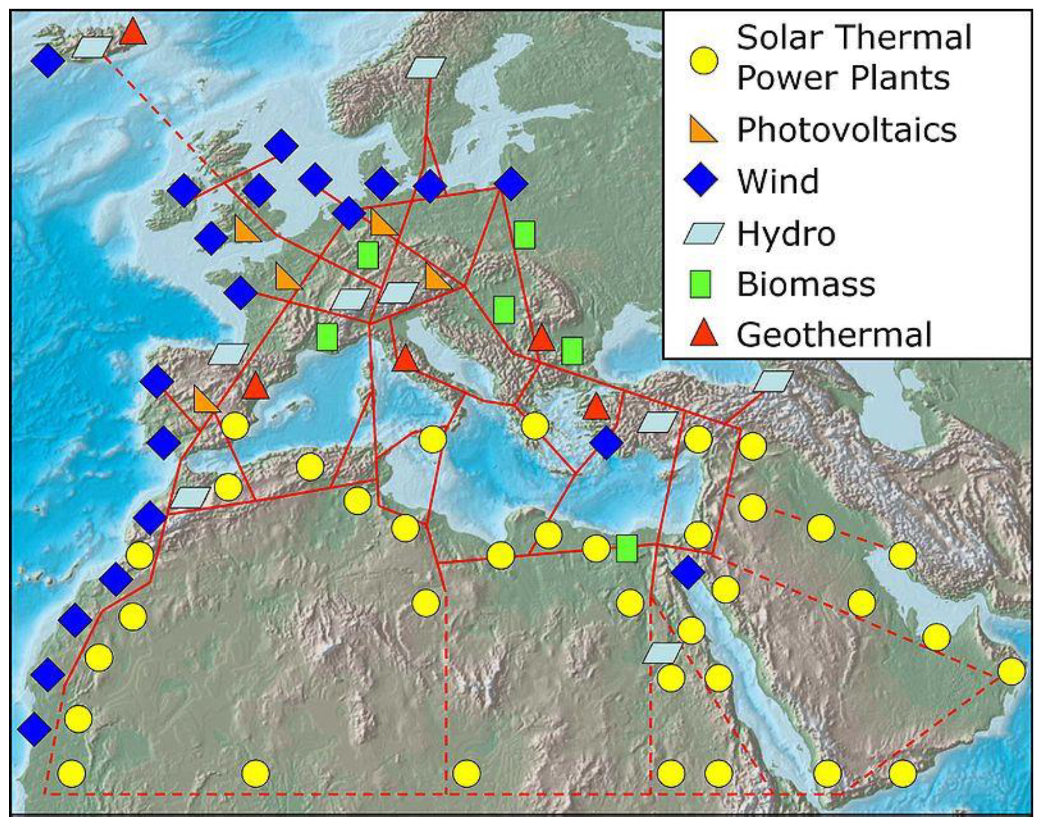
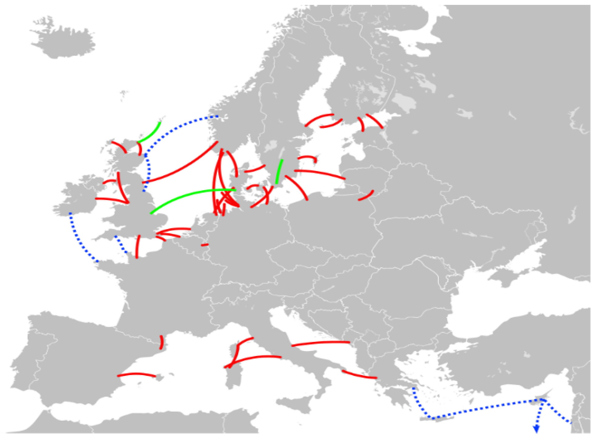
:1. Introduction
- Centralized infrastructure
- Decentralized infrastructure
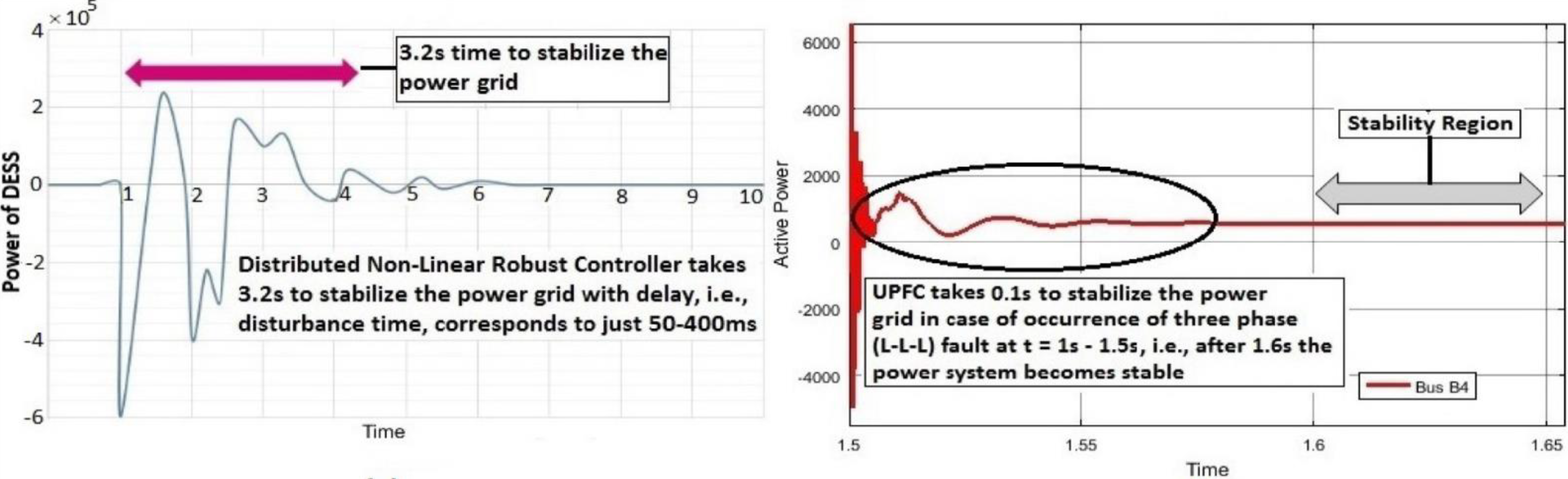
- Providing transients stability and resilience in a complex network of SSGs within a short span of time of around 0.1s using a UPFC;
- Multiple faults analysis can also be performed in SSGs power infrastructure to show the superiority of UPFC for achieving stability in a very short span of time as compared to other FACTS devices;
- Although SSG projects and ideas have received positive reviews, their development is still a challenging task. Therefore, extensive simulation studies employing accurate RERs models could be used in this research to analyze and investigate various stability problems arising from the integration of many clusters of RERs in SSGs. Moreover, how network operators will resolve these instability issues using a UPFC will also be a significant part of this research work.
2. Transient Stability Analysis Methods
3. Techniques for Enhancing Transient Stability
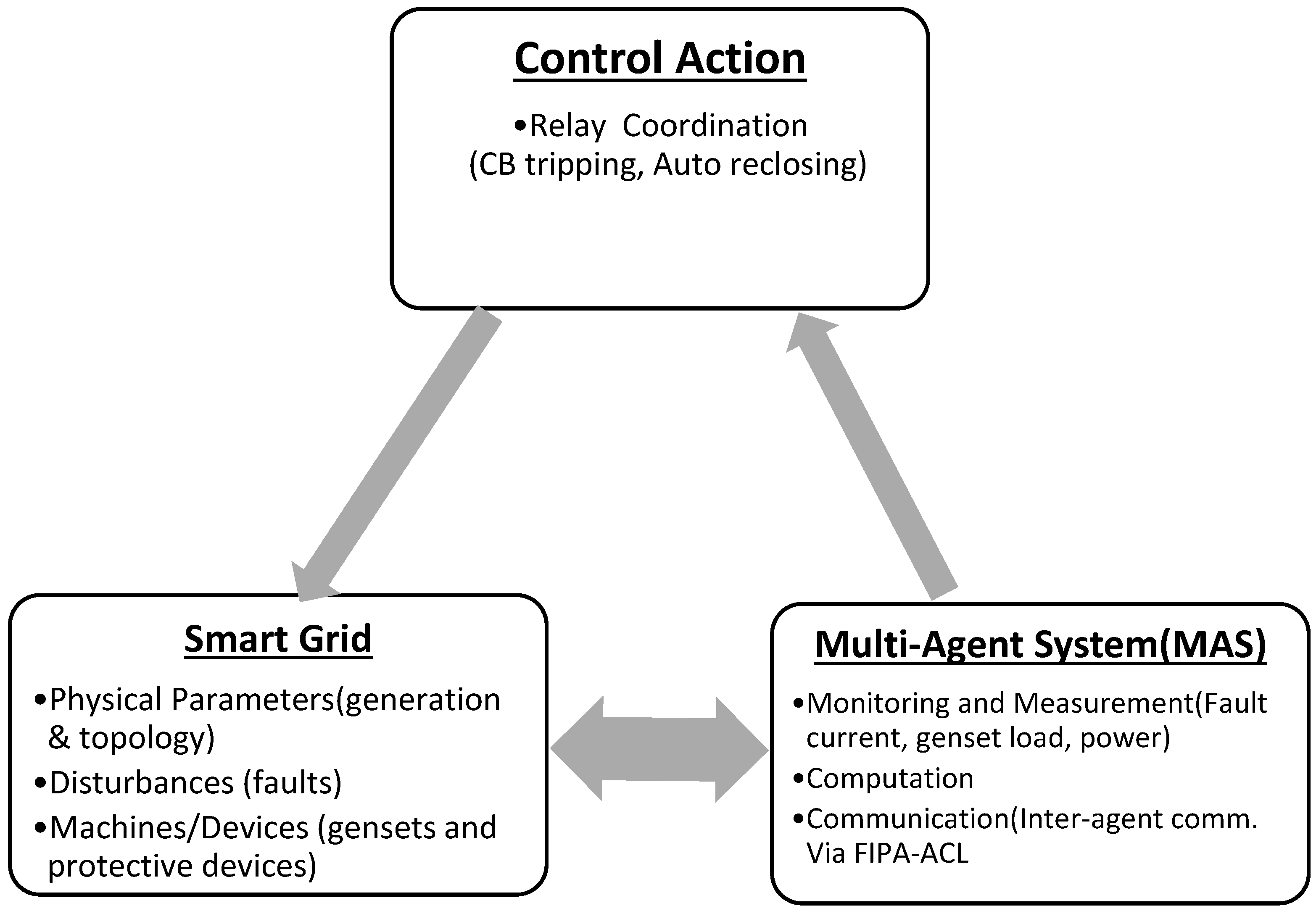
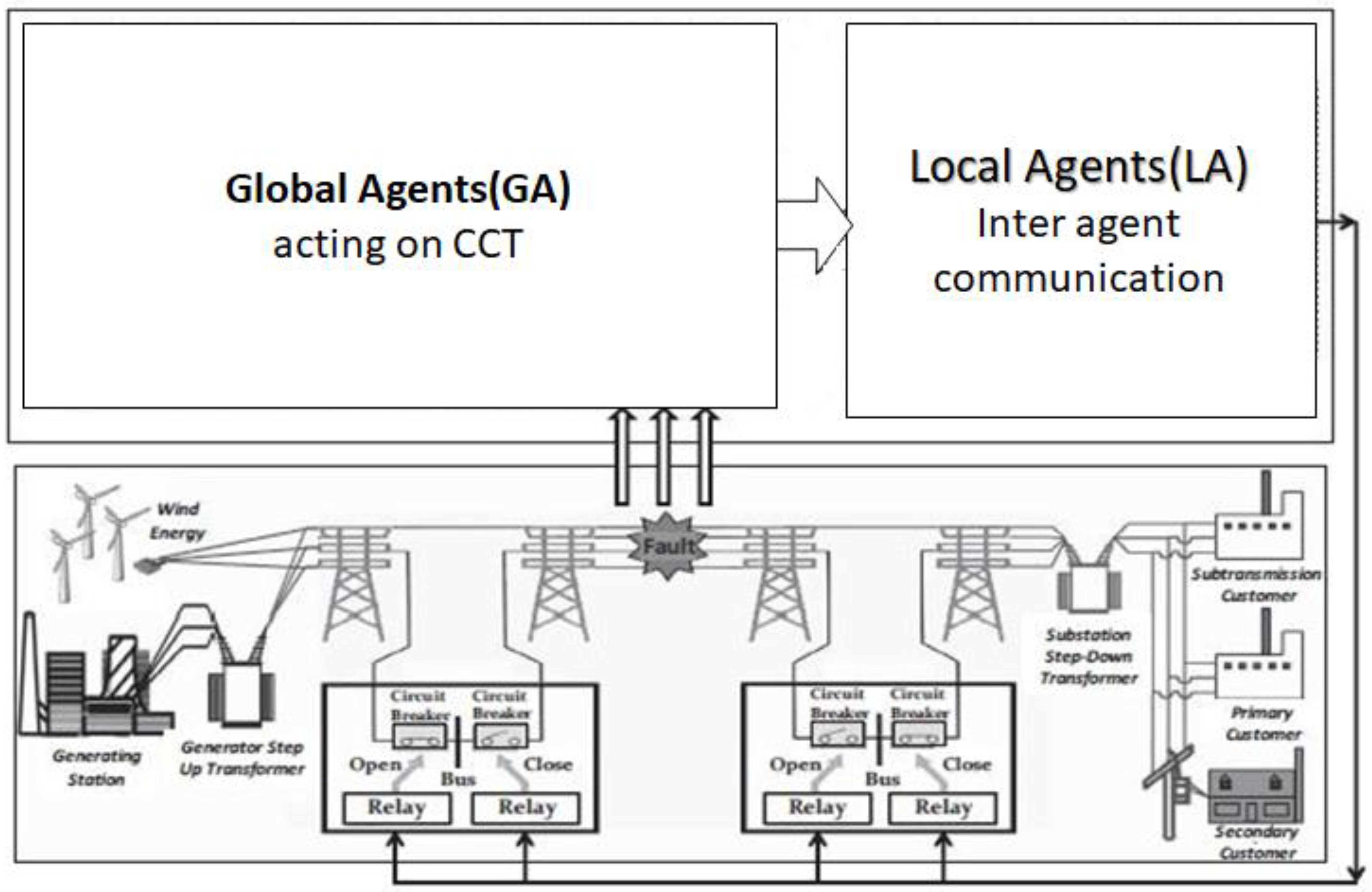
3.1. Multi-Agent-Based Technique
3.2. Incorporation of FACTS Devices
- Static compensators (STATCOMs);
- Unified power flow controllers (UPFCs);
- Static synchronous series compensators (SSSCs);
- Thyristor controlled shunt reactor (TCSR).
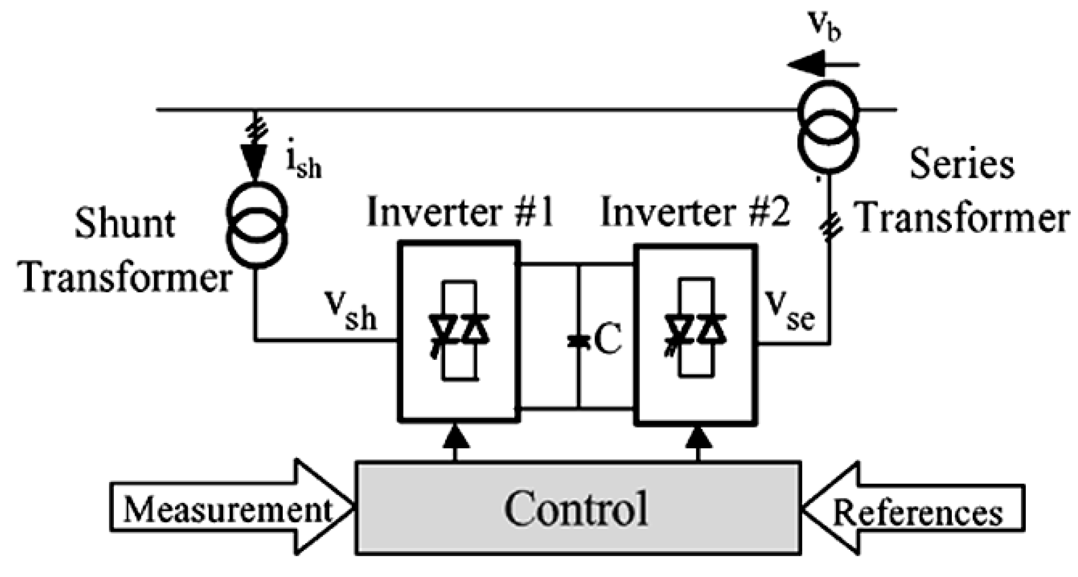
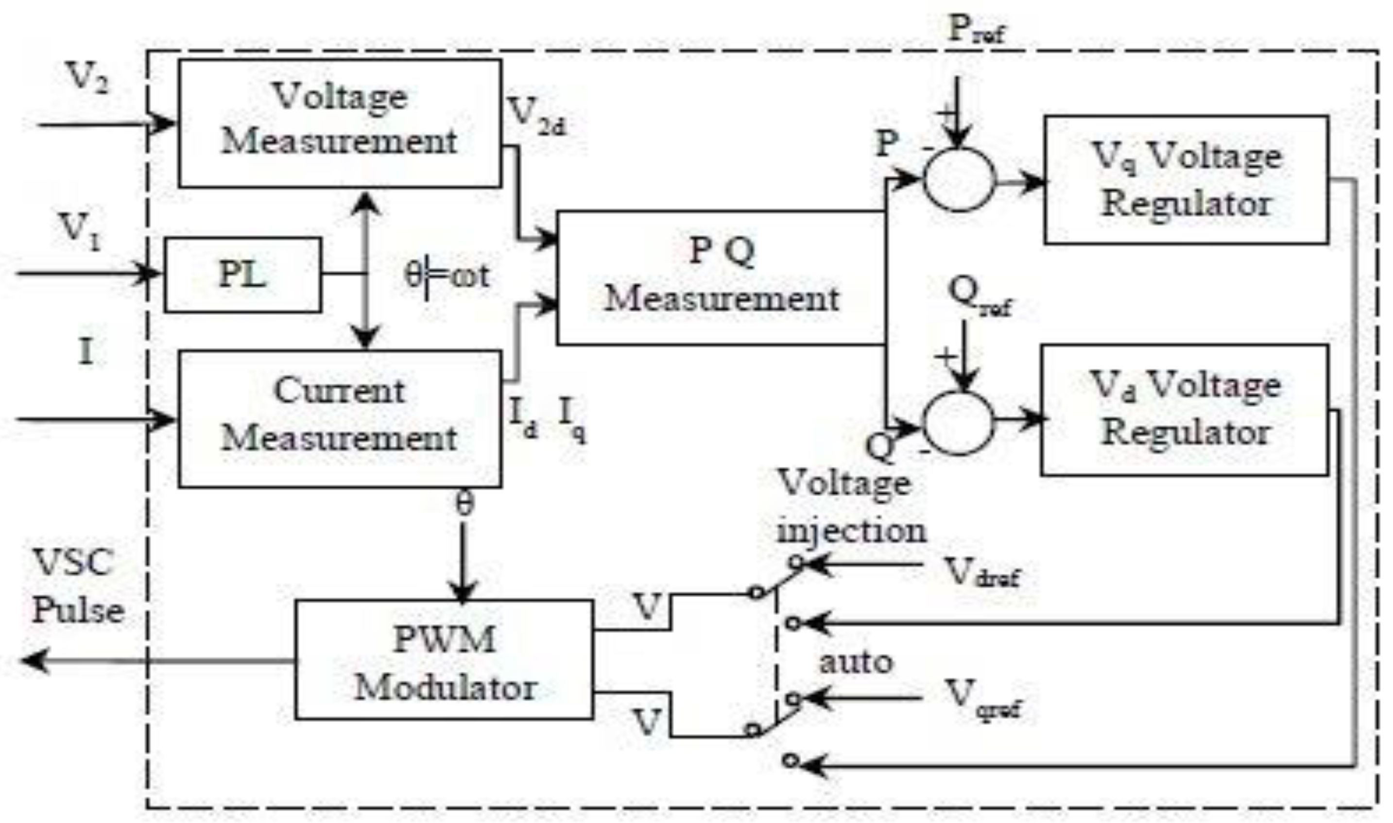
3.2.1. Insertion of UPFC
3.2.2. Utilization of the STATCOMS
3.2.3. Utilization of the TCSC
4. Algorithms for Transient Stability Enhancement
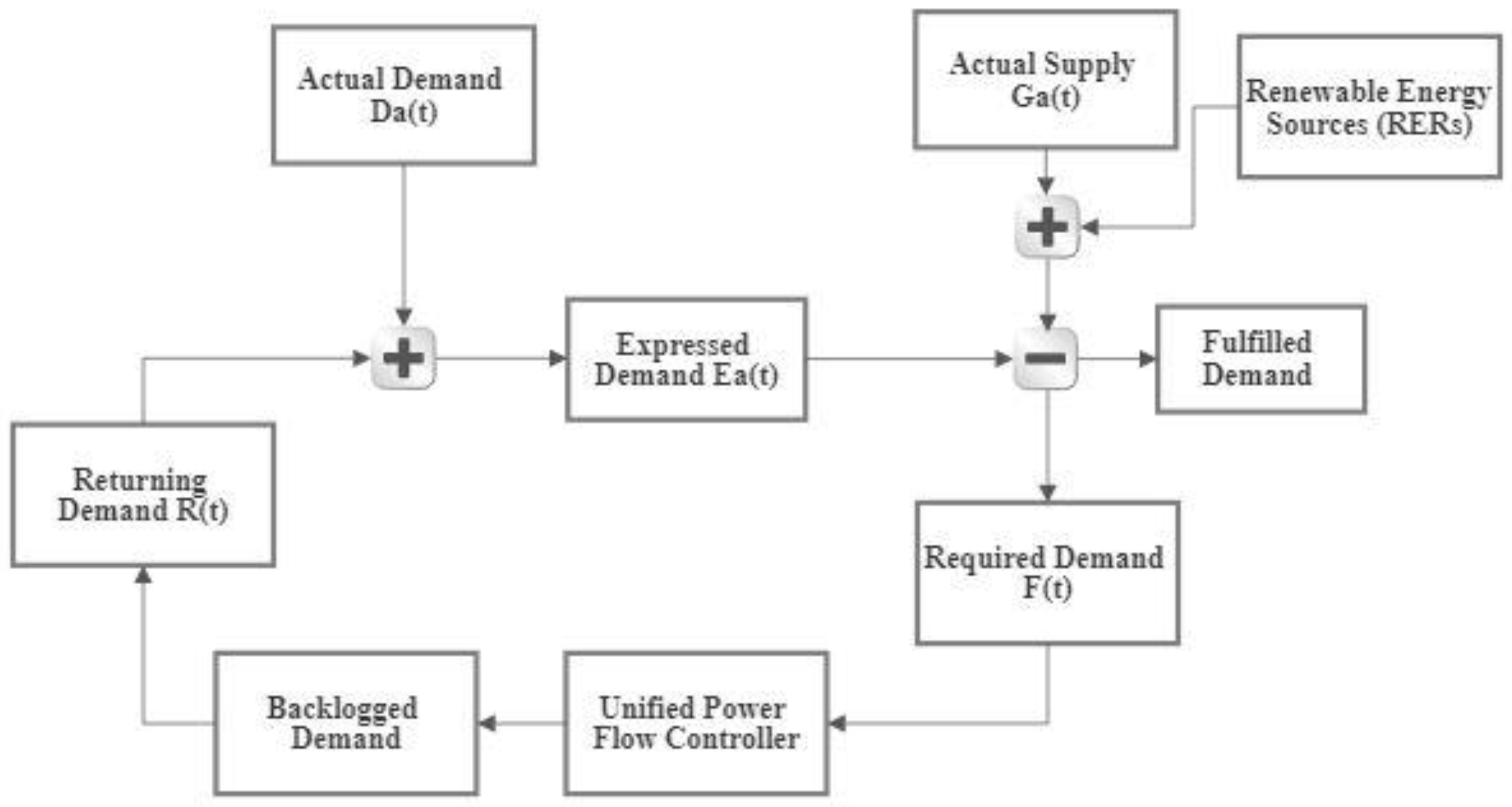
5. Mathematical Modelling
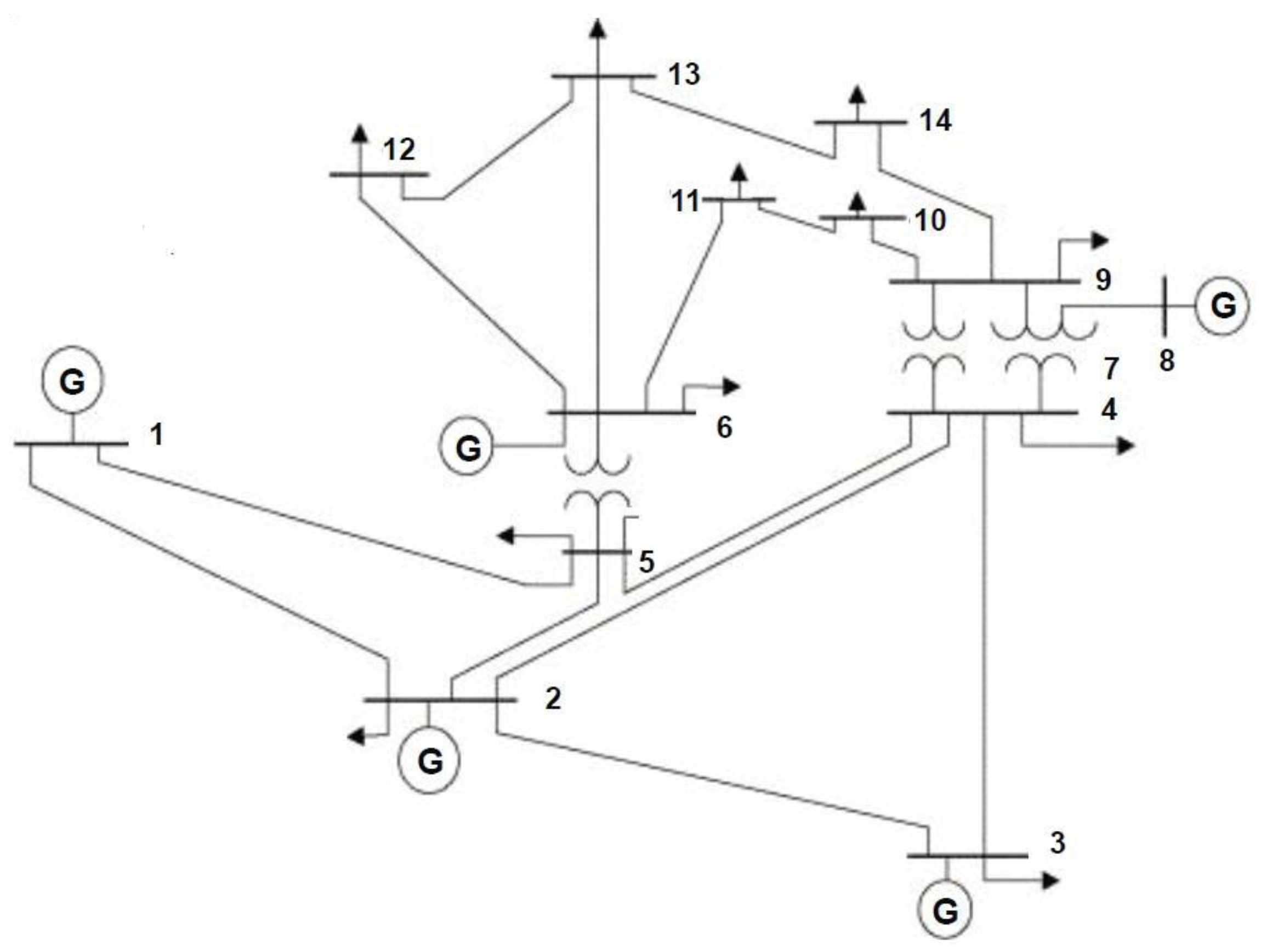
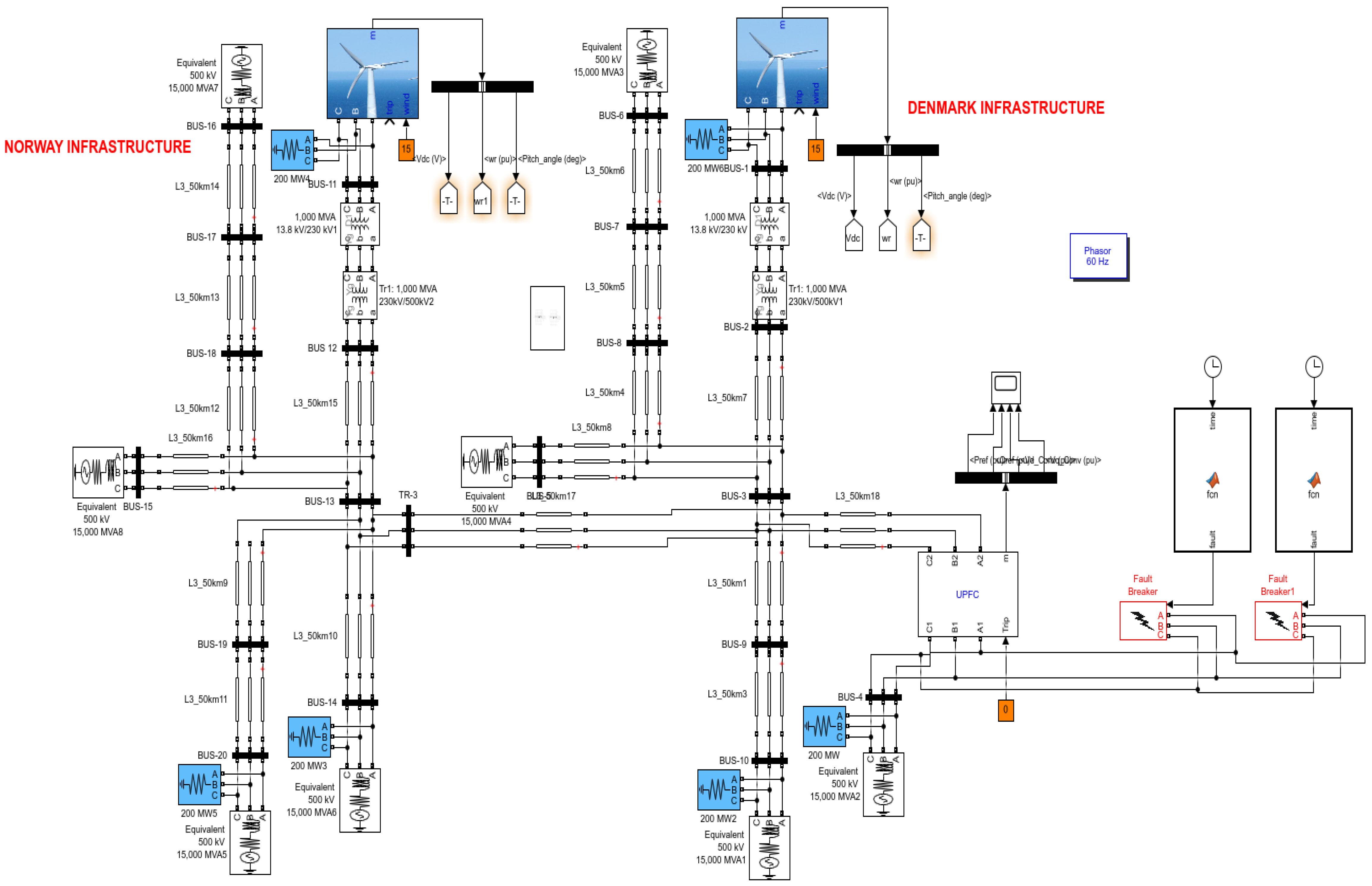
6. Designing of Clusters
7. Simulations and Results
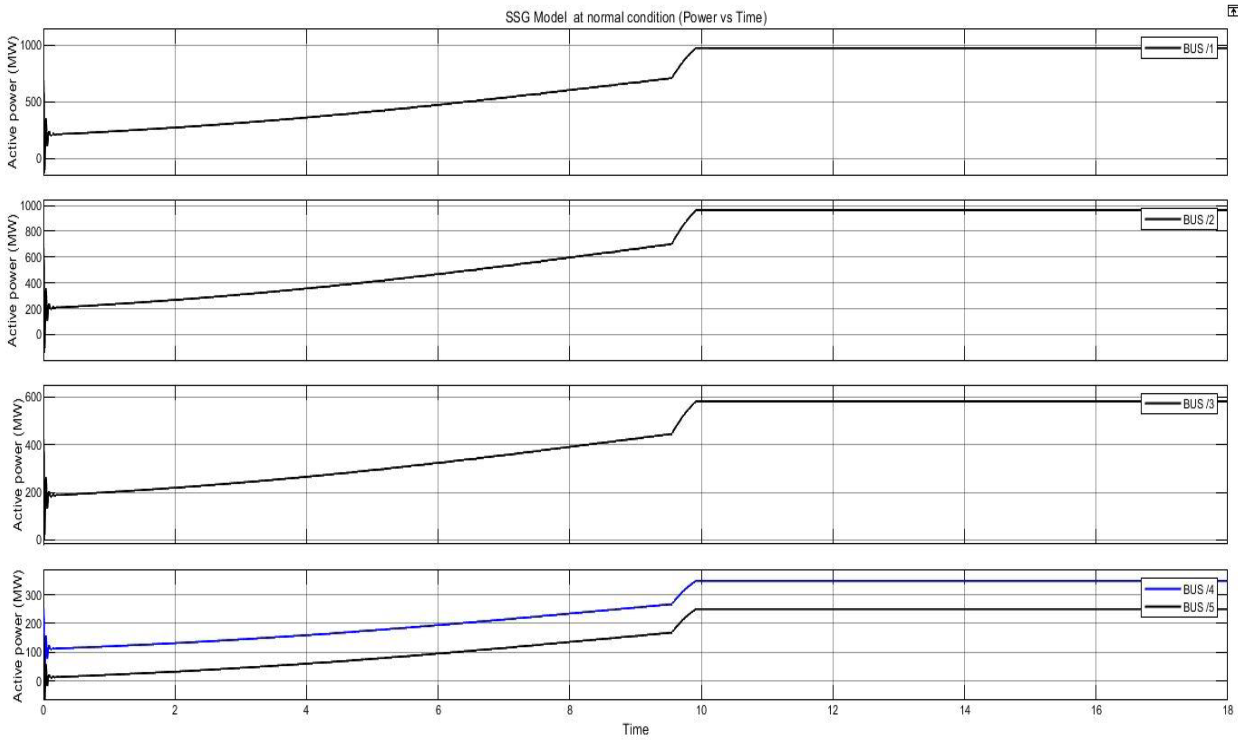
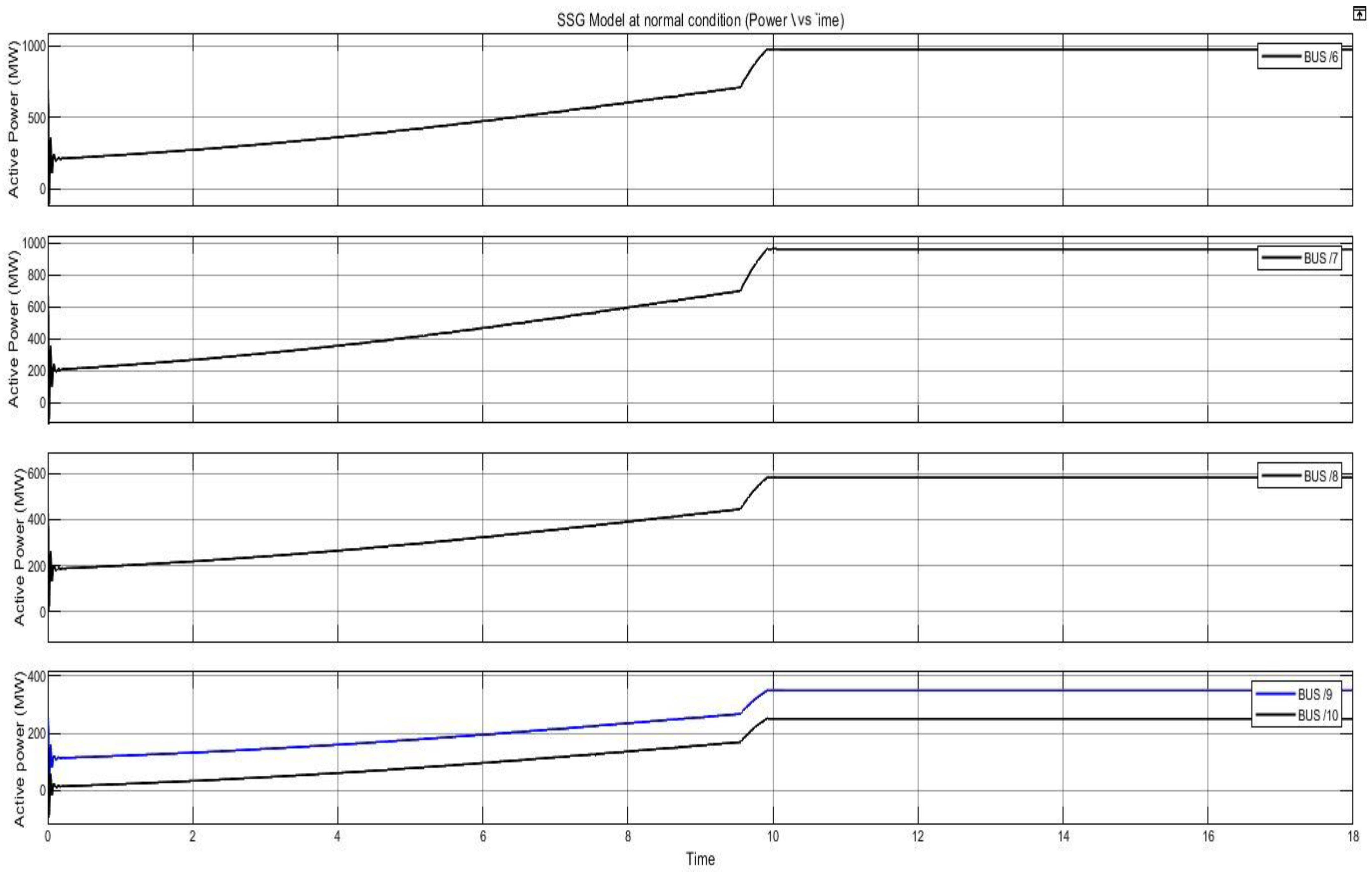
7.1. Case 1. System in Normal State and No-Fault Is Introduced
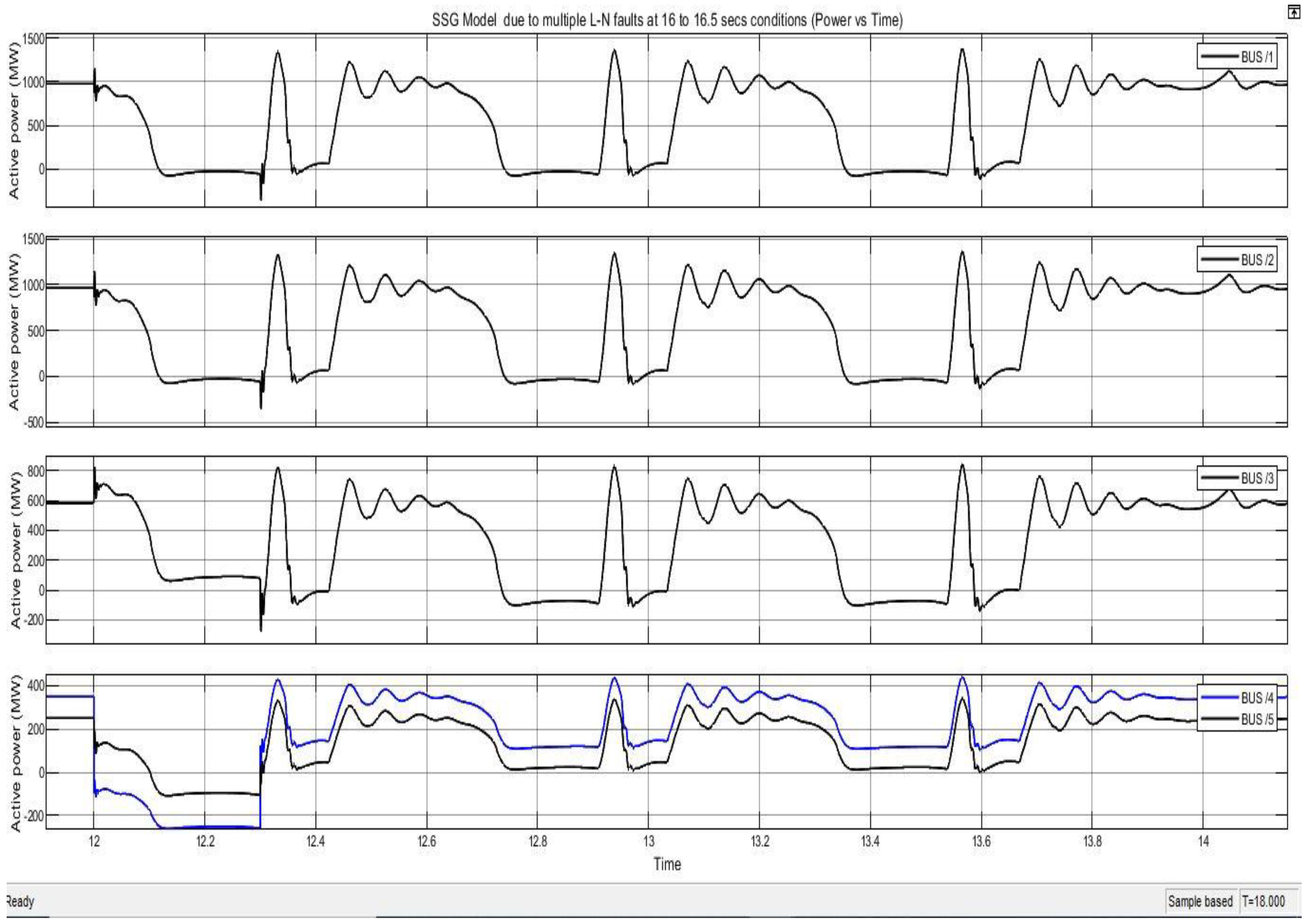
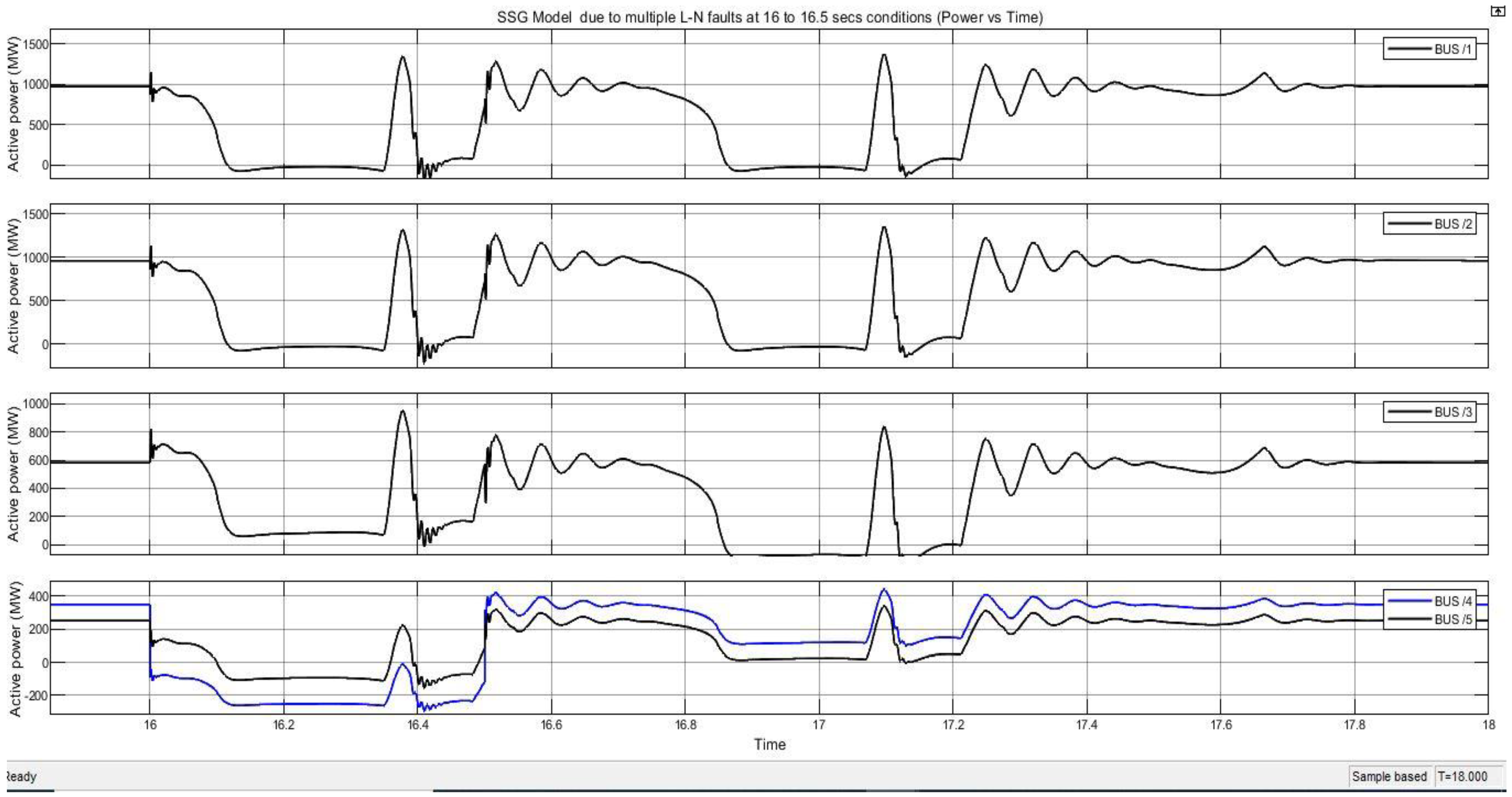
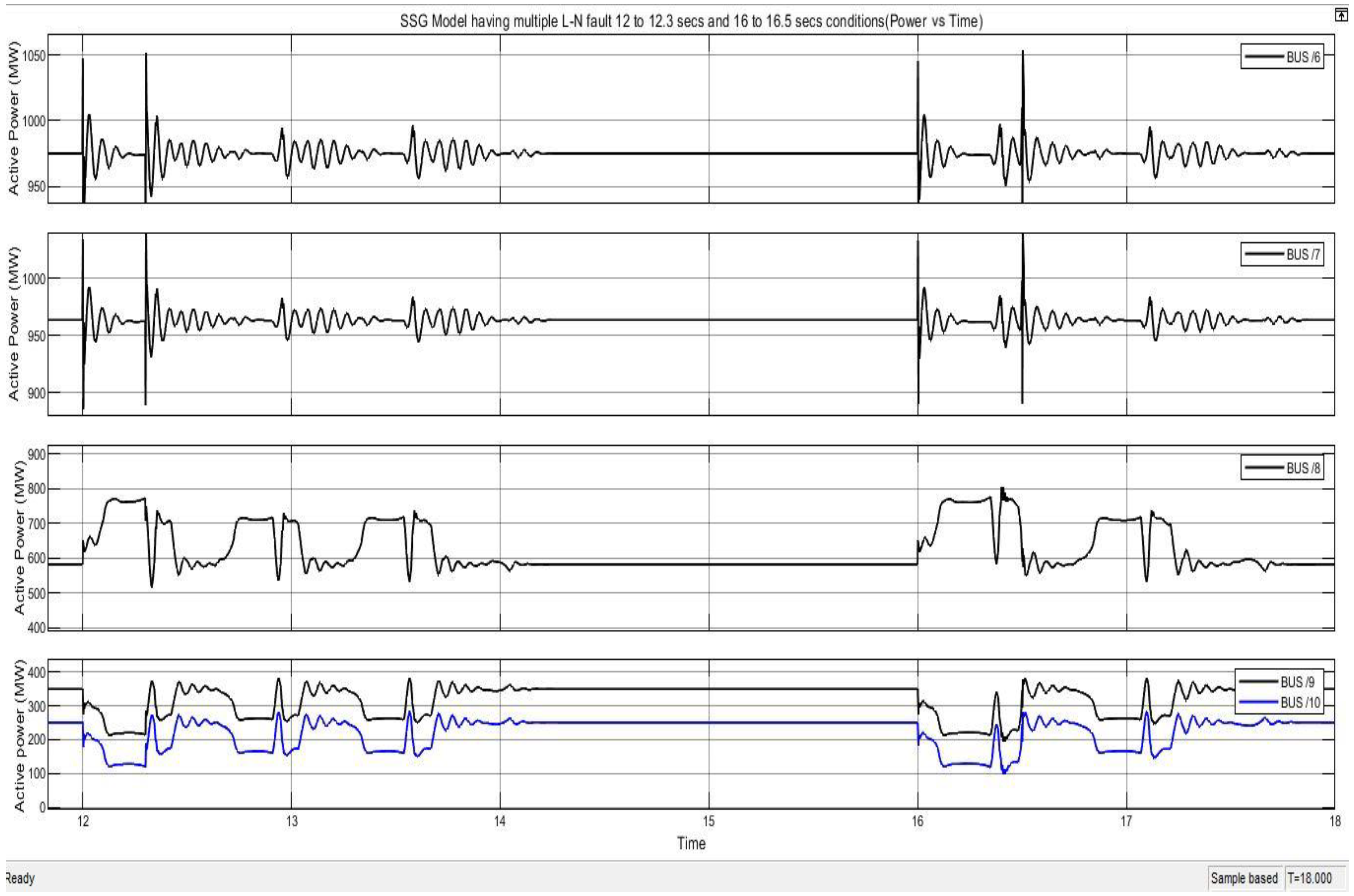
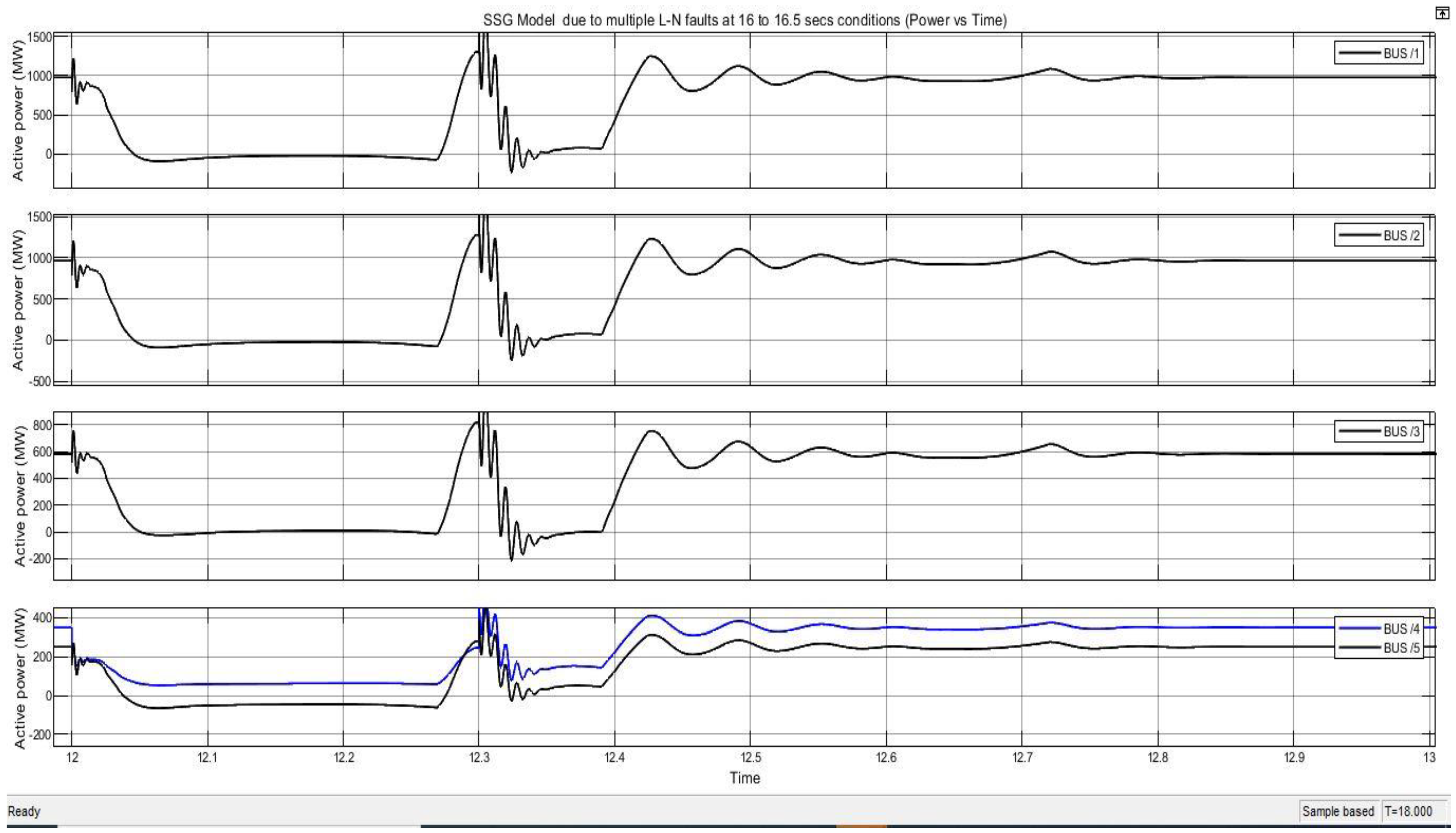
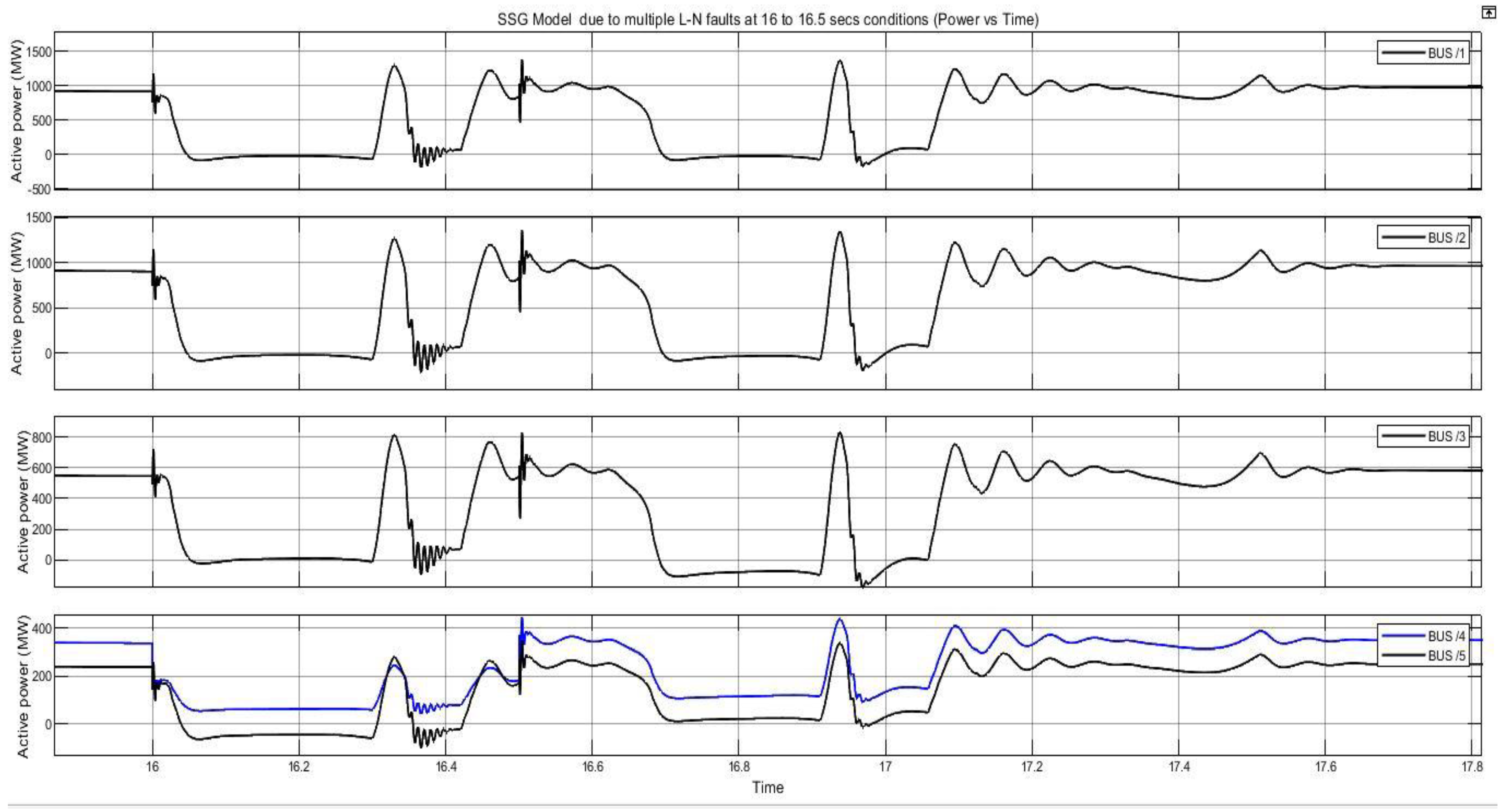
7.2. Case 2. System in Instability State, and Multiple L-GFaults Are Introduced
function fault = fcn(time)%#codegenfault = 0;if (time >= 12 && time <= 12.3)fault = 1;end
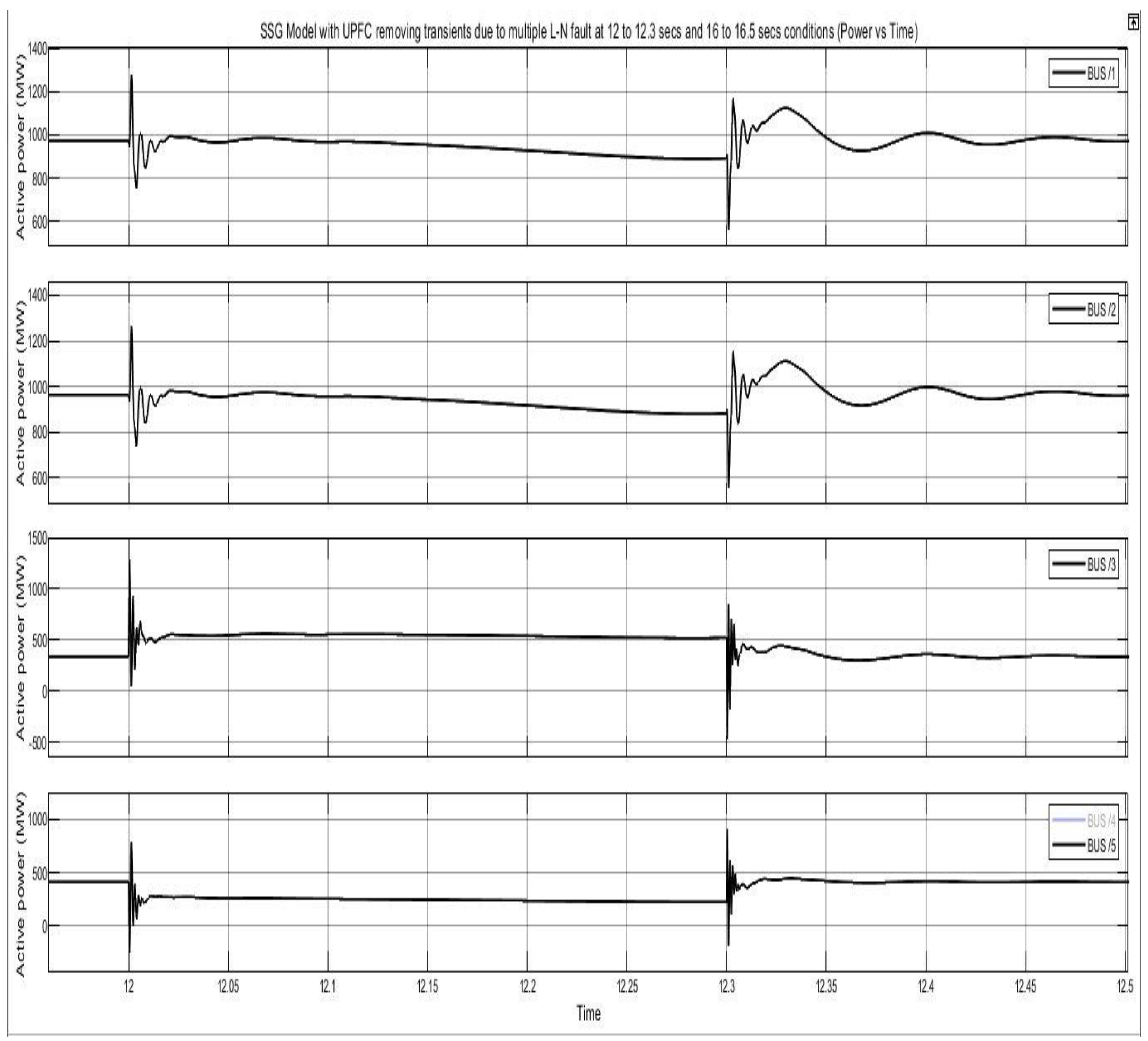
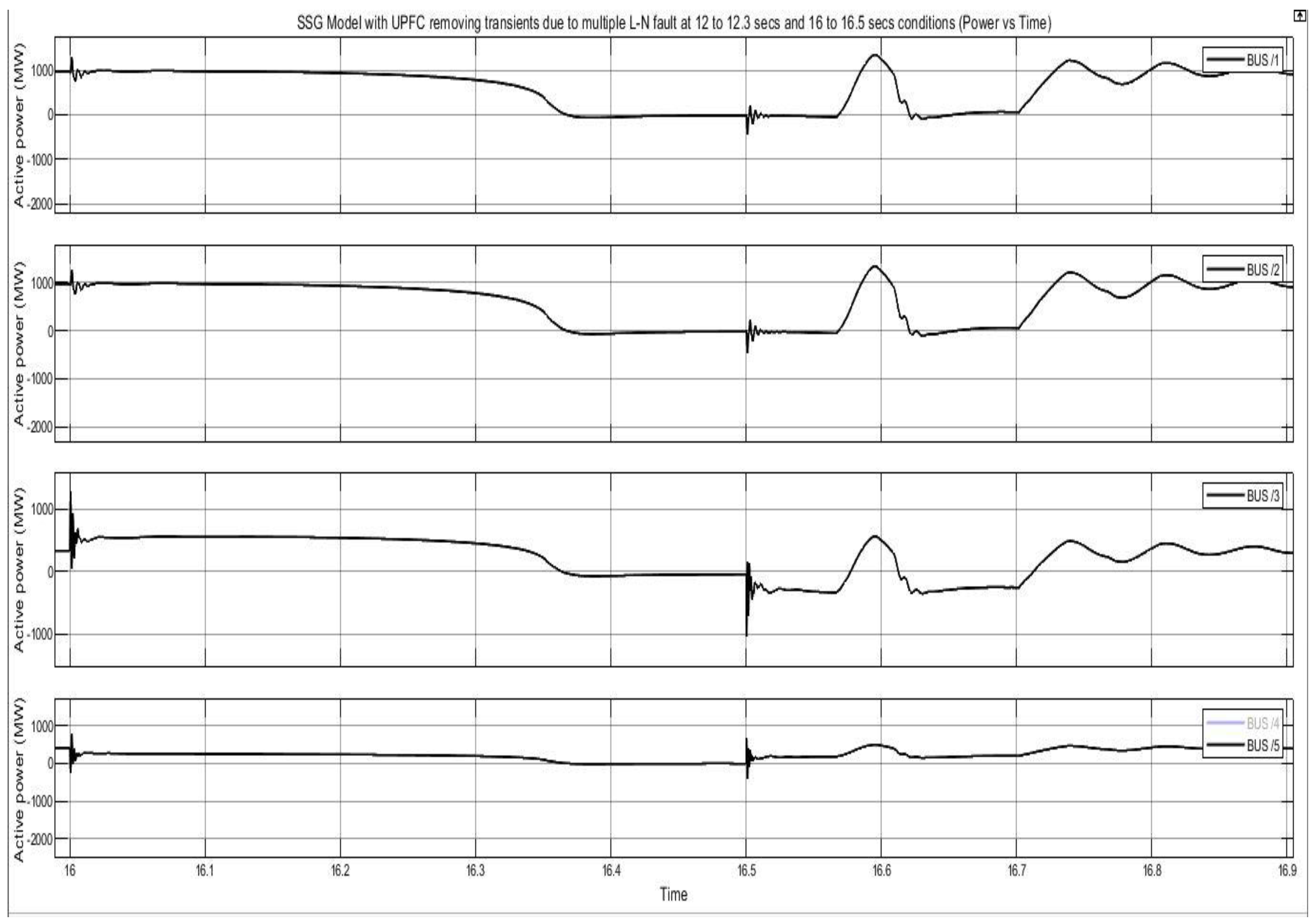
7.3. Case 3. By Incorporation of UPFC, and Multiple L-GFaults Are Also Inserted
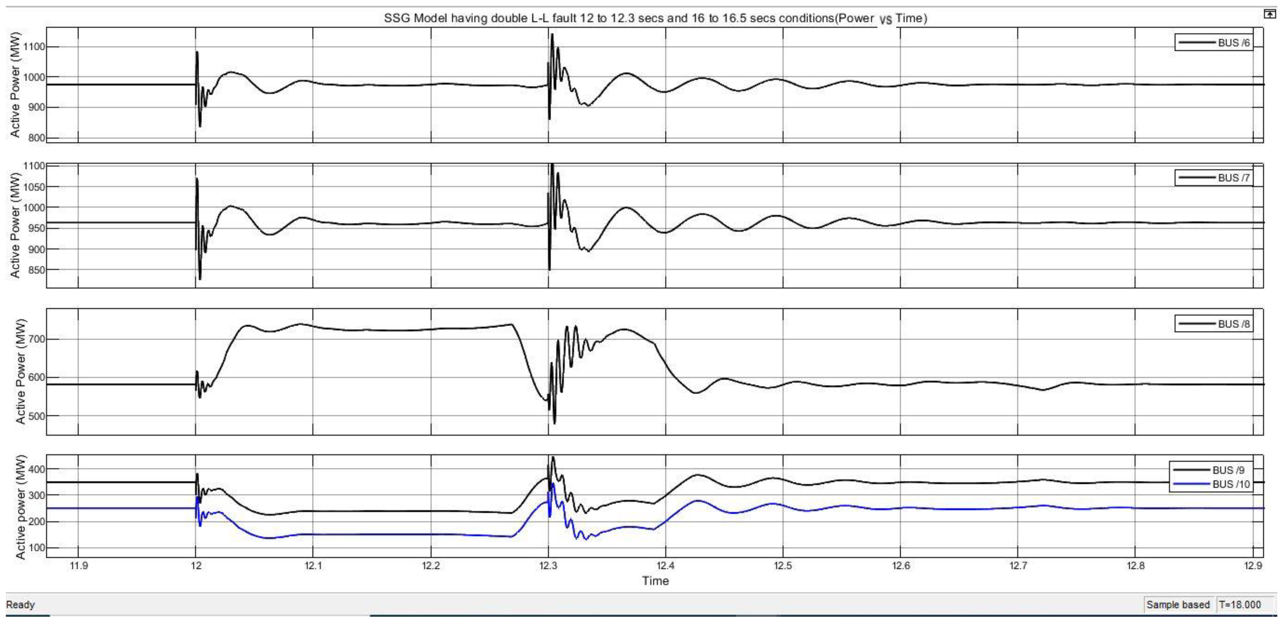
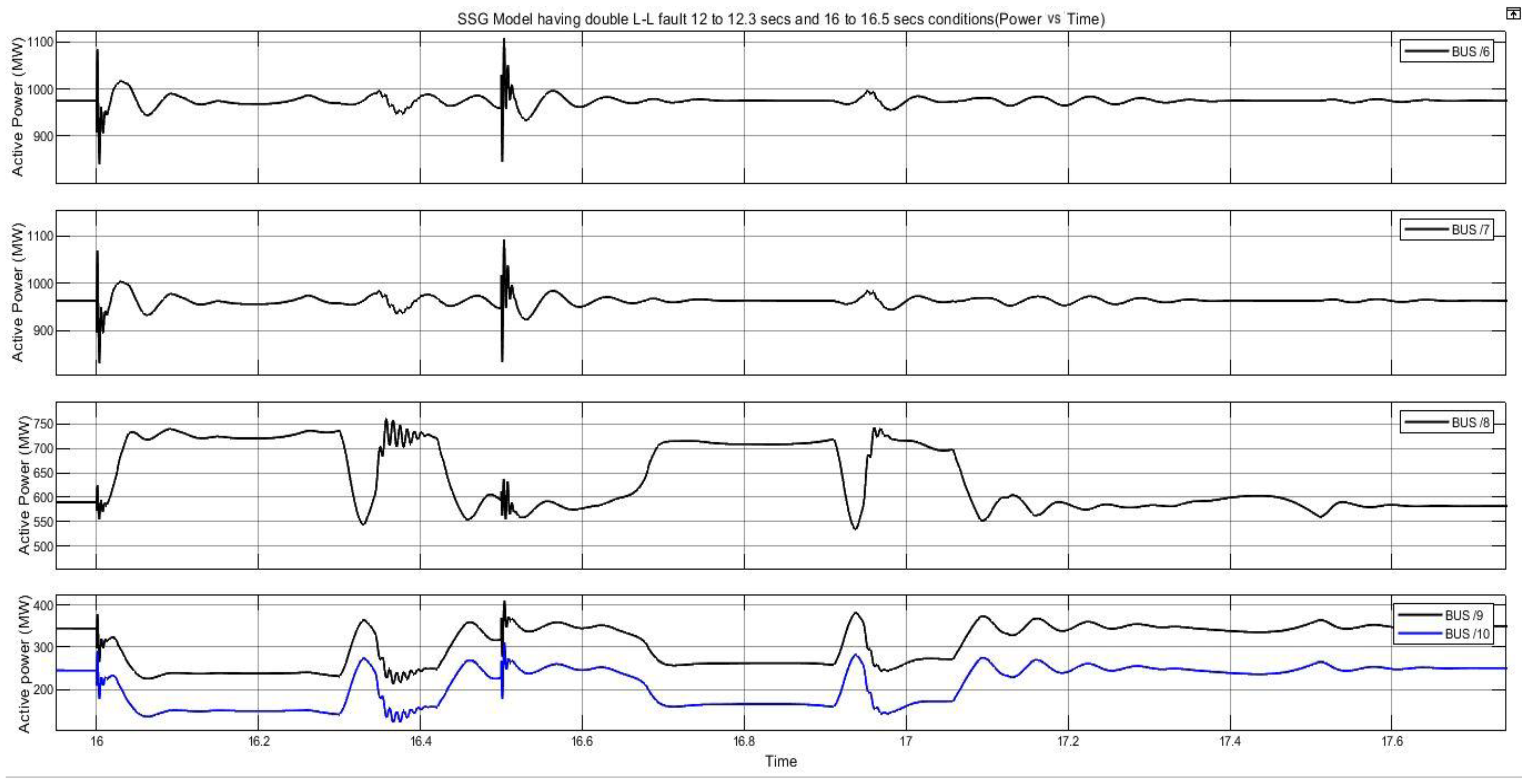
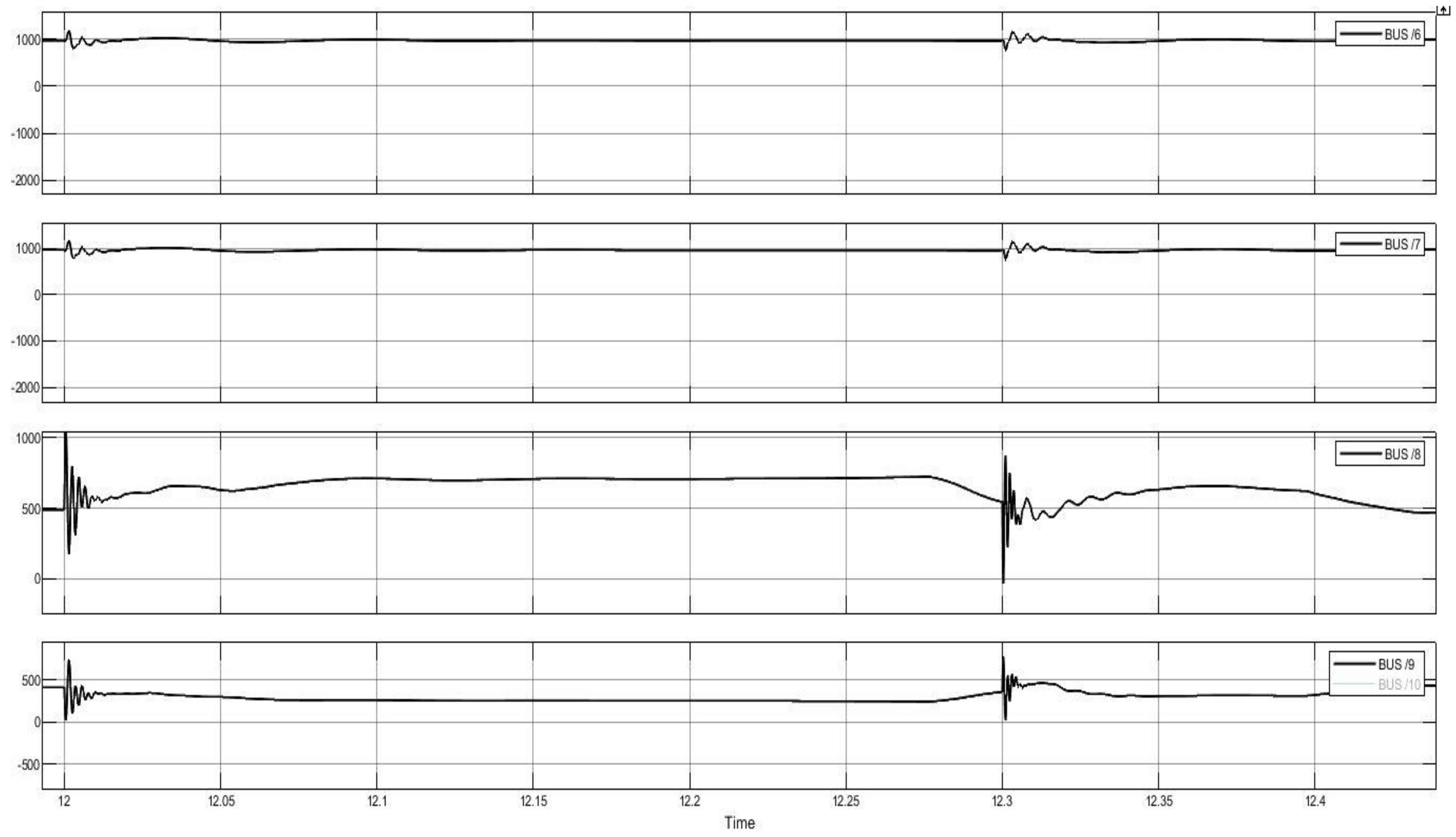
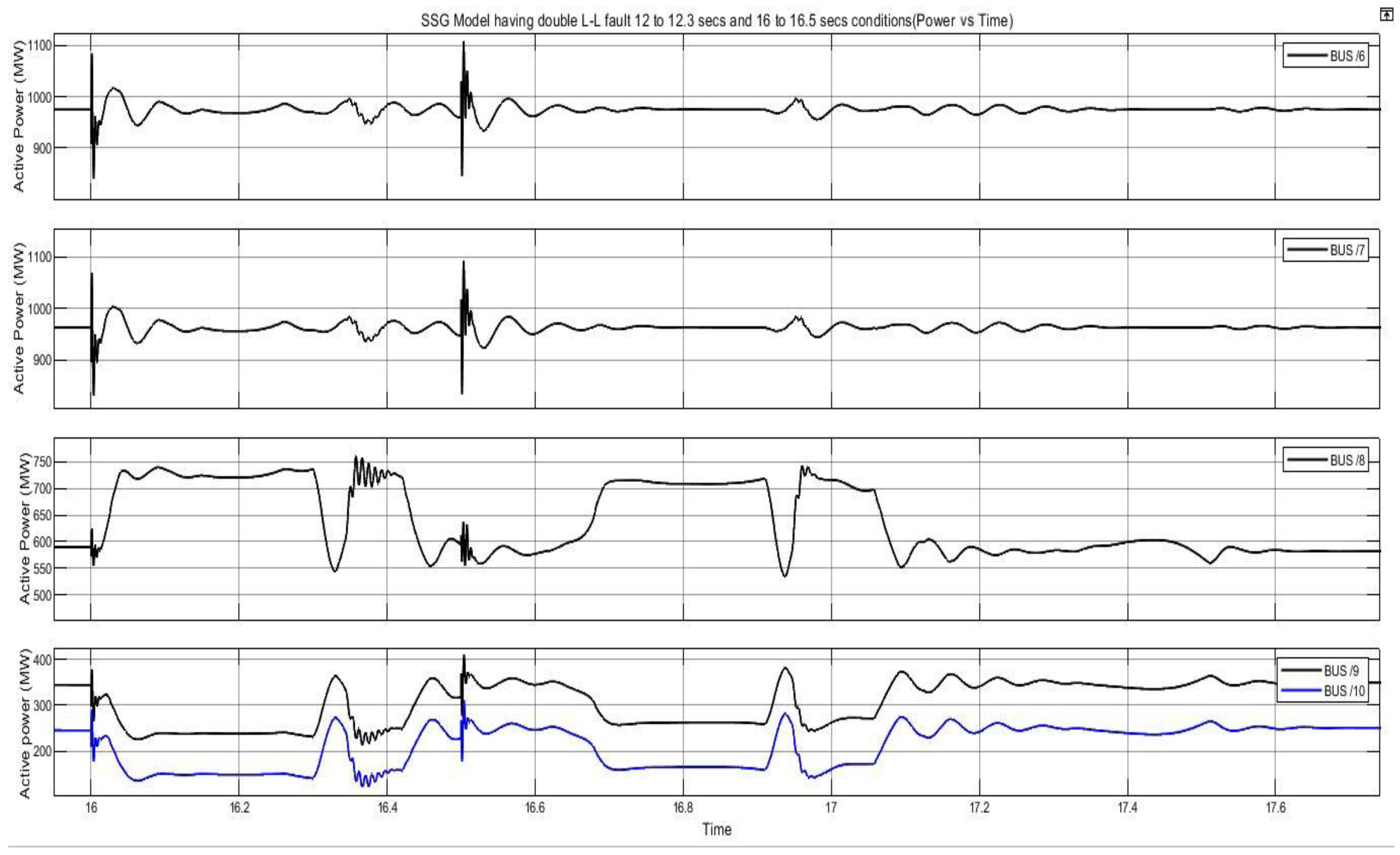
7.4. Case 4. System in Instability State, and Multiple Double L-LFaults Are Introduced
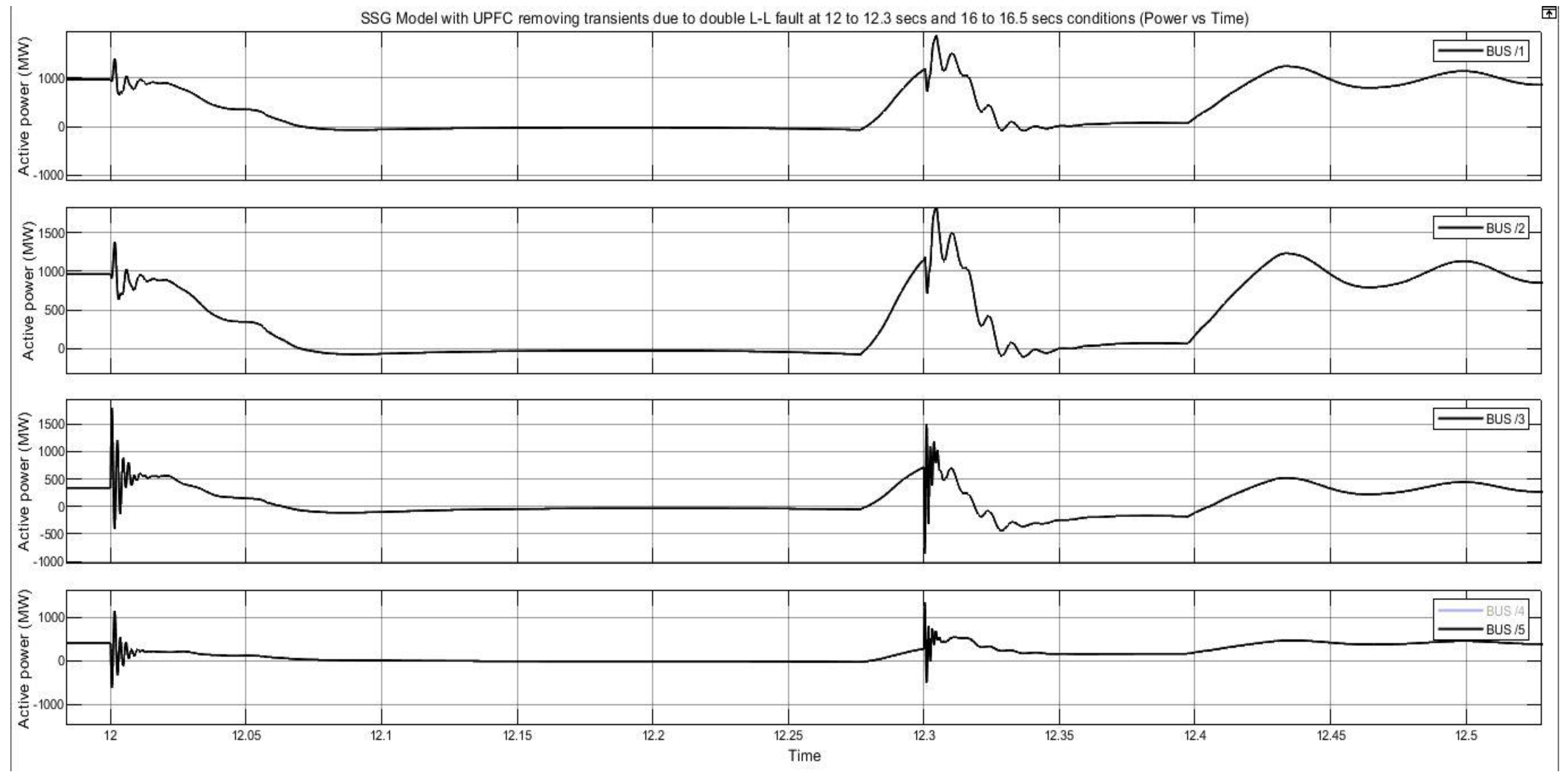
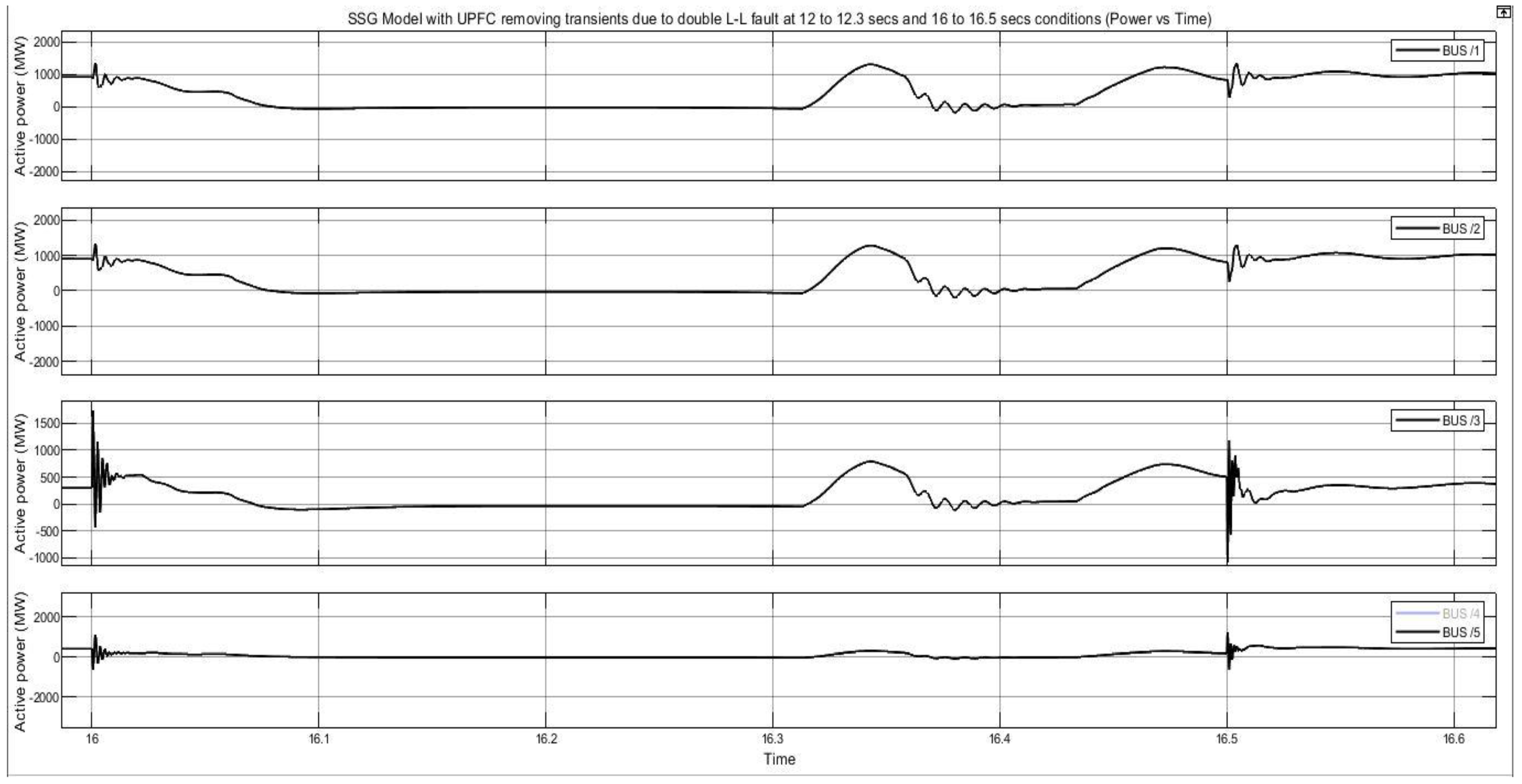
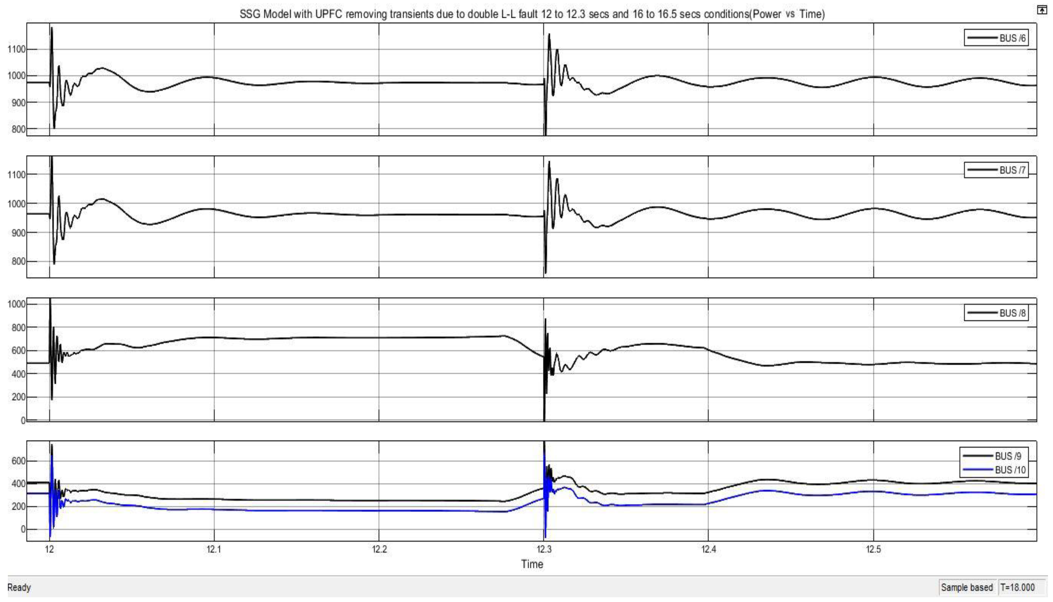
7.5. Case 5. By Incorporation of UPFC, and Multiple Double L-L Faults Are Also Injected
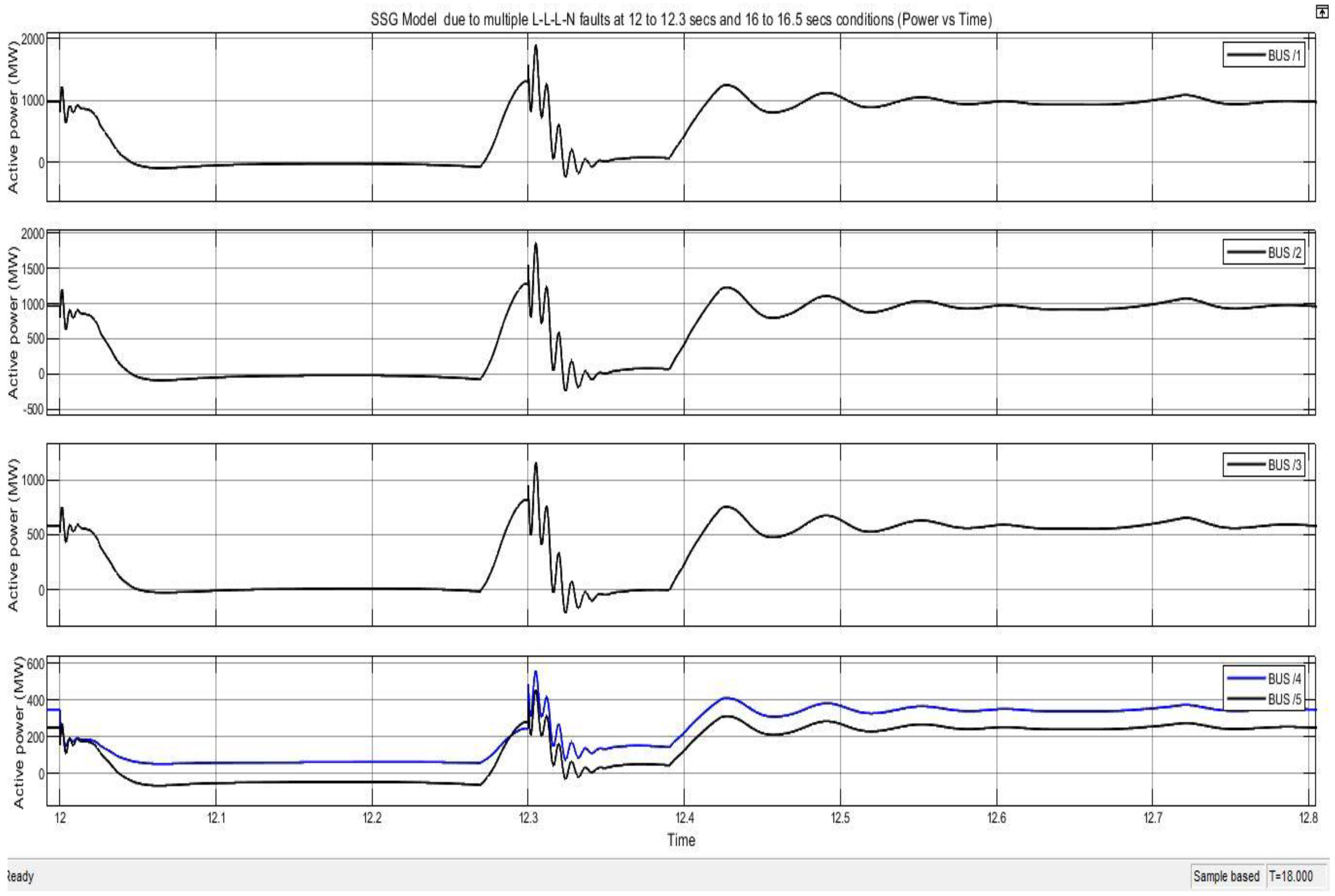
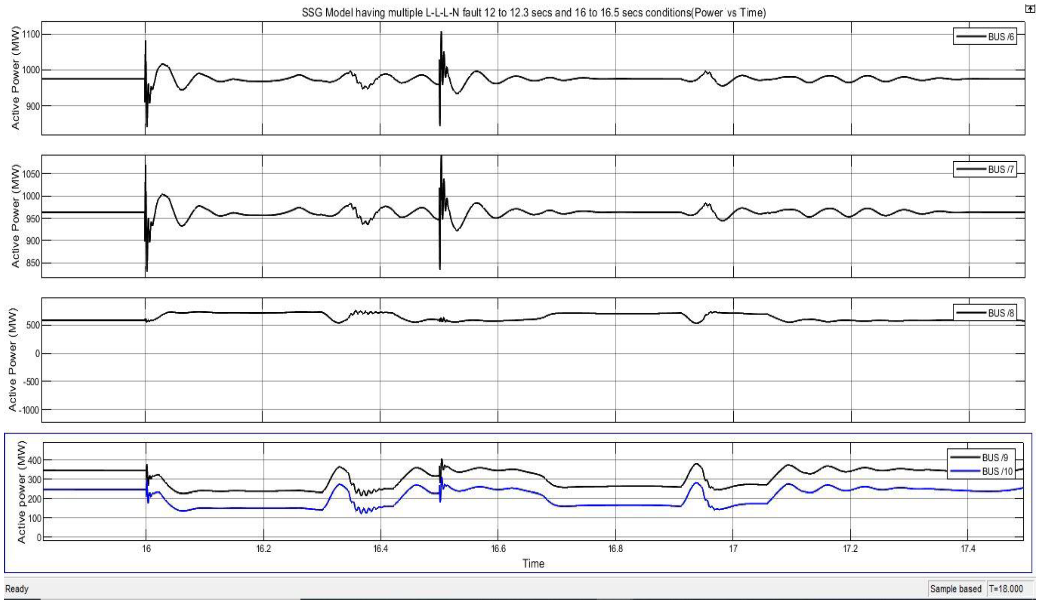
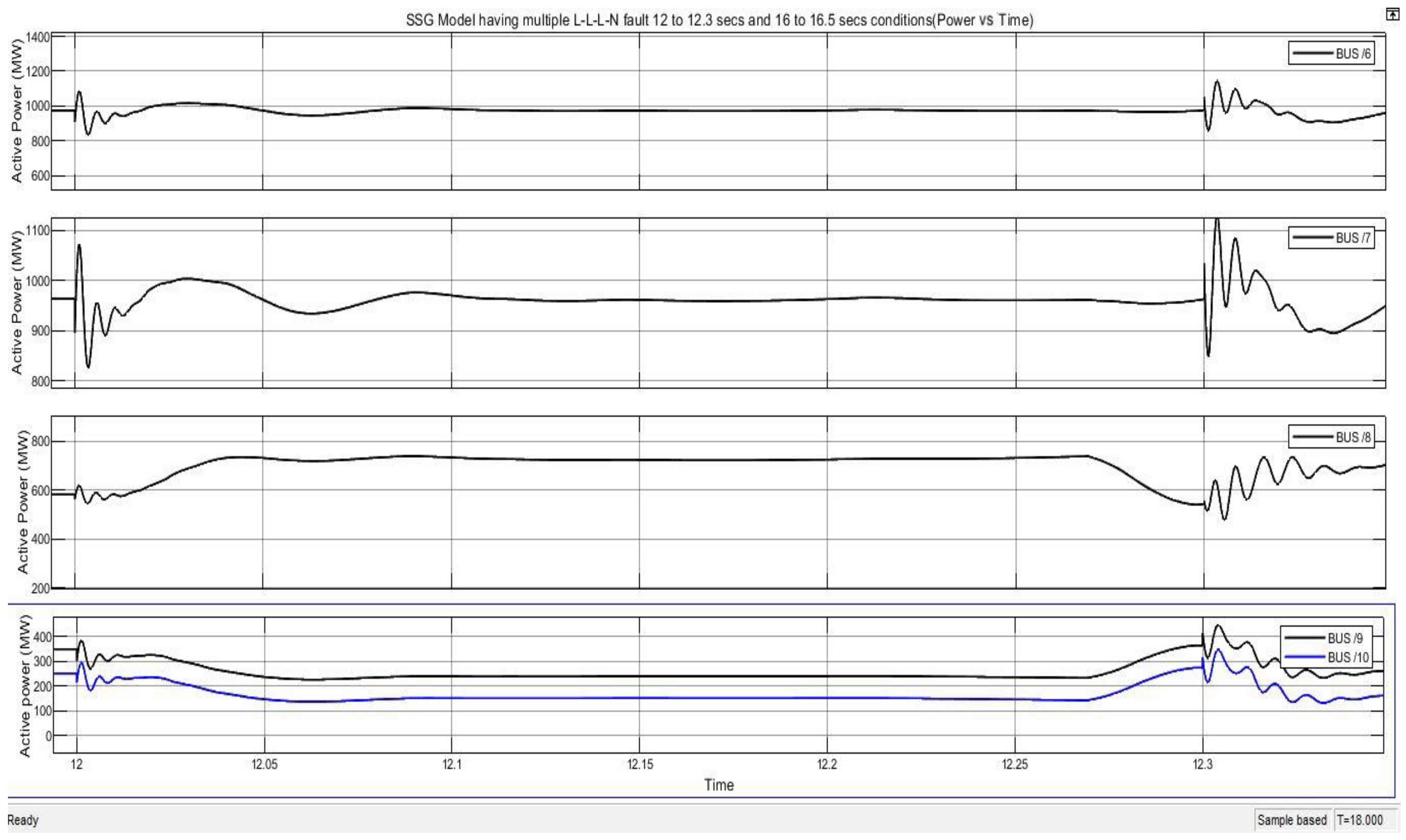
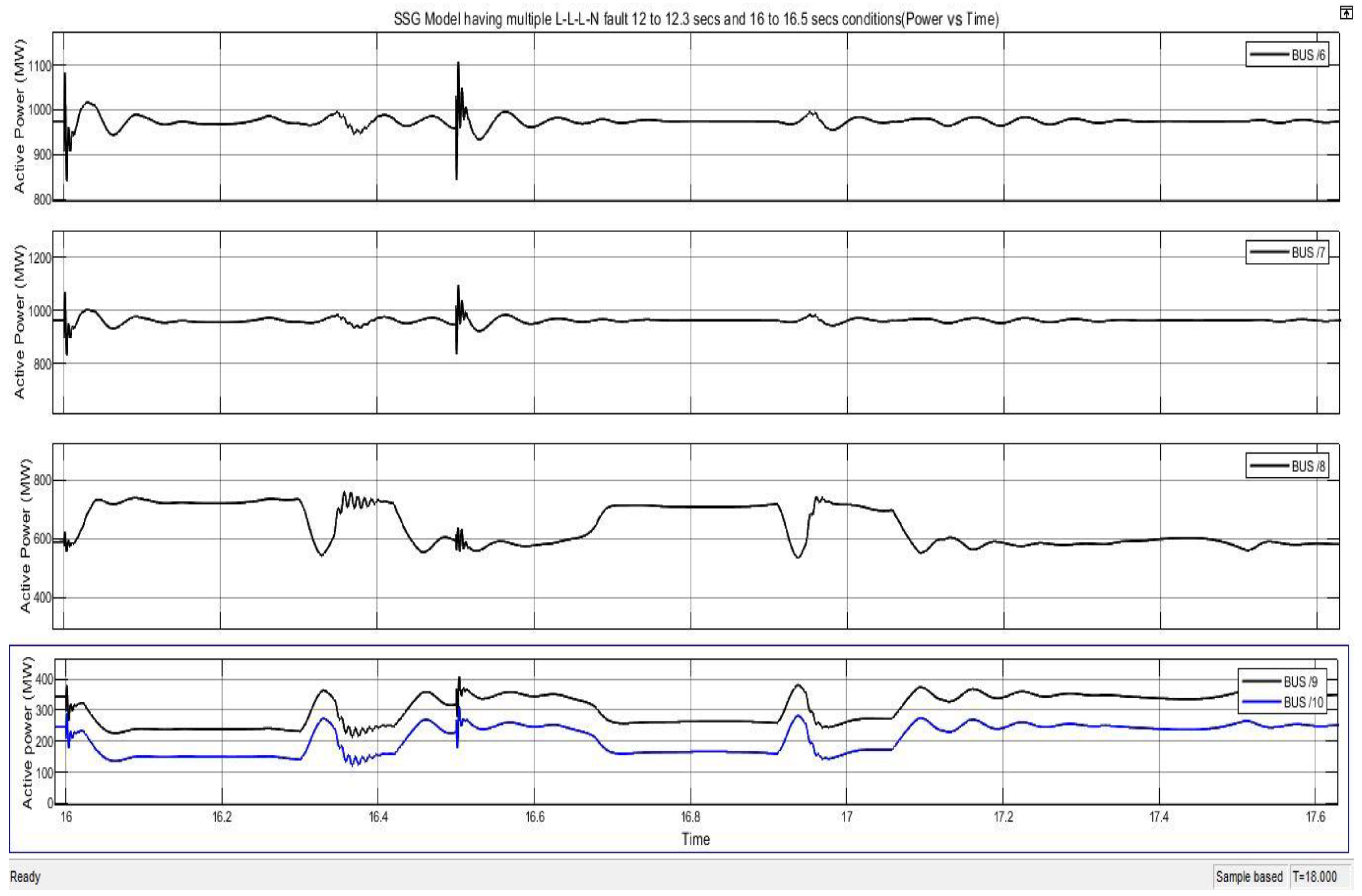
7.6. Case 6. System in Instability State, and Multiple L-L-L-NFaults Are Introduced
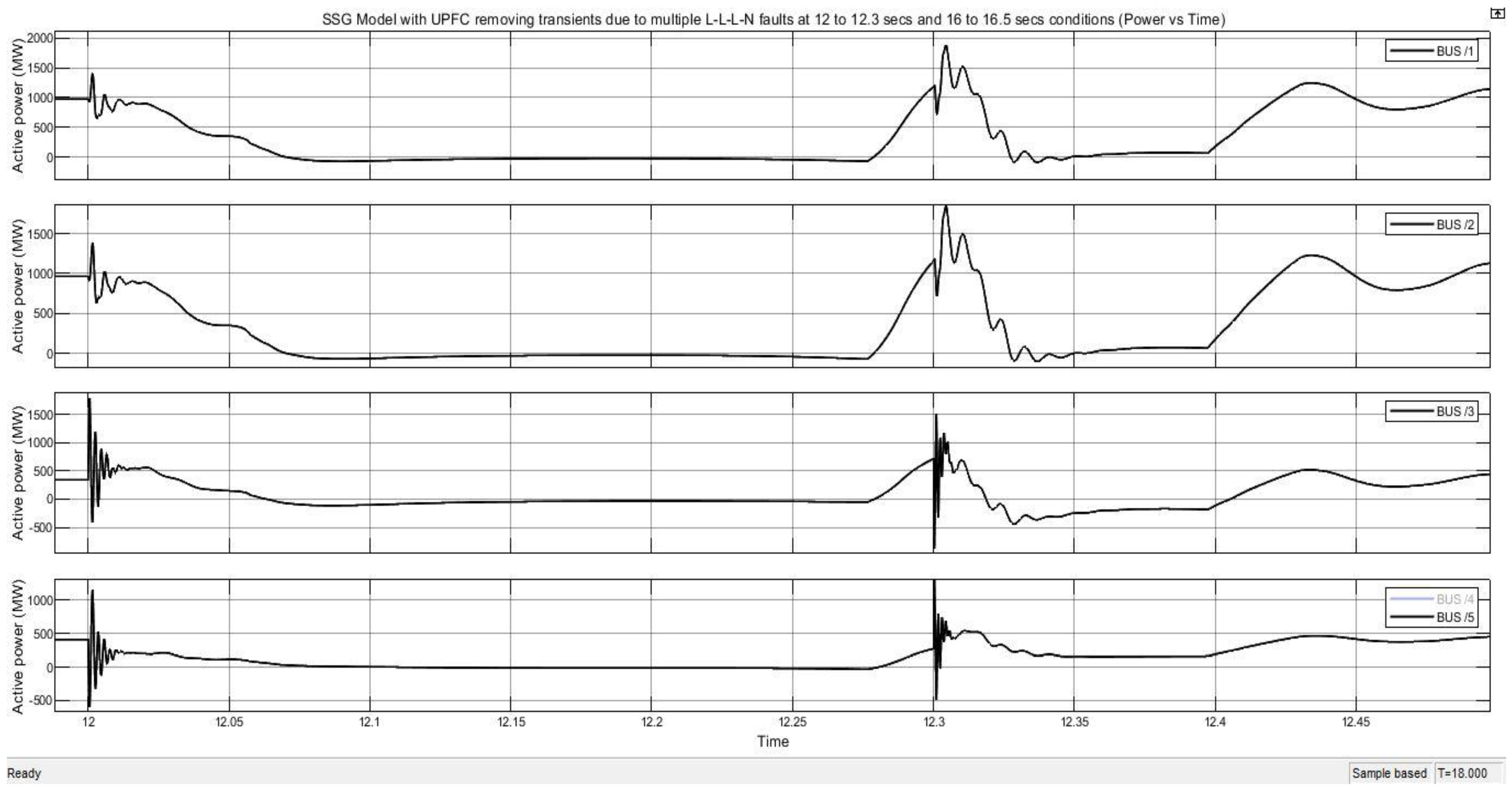
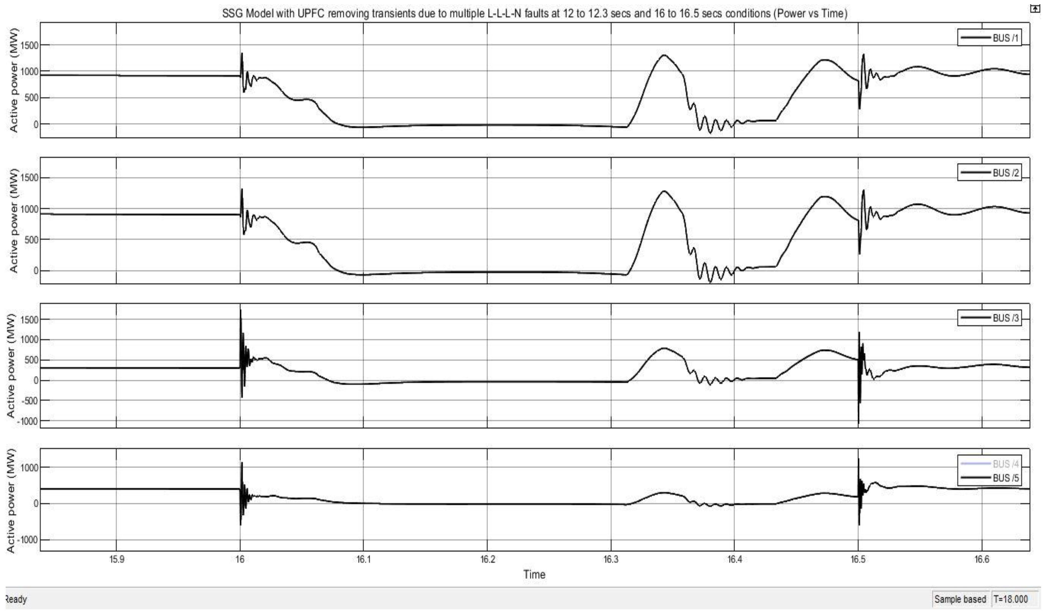
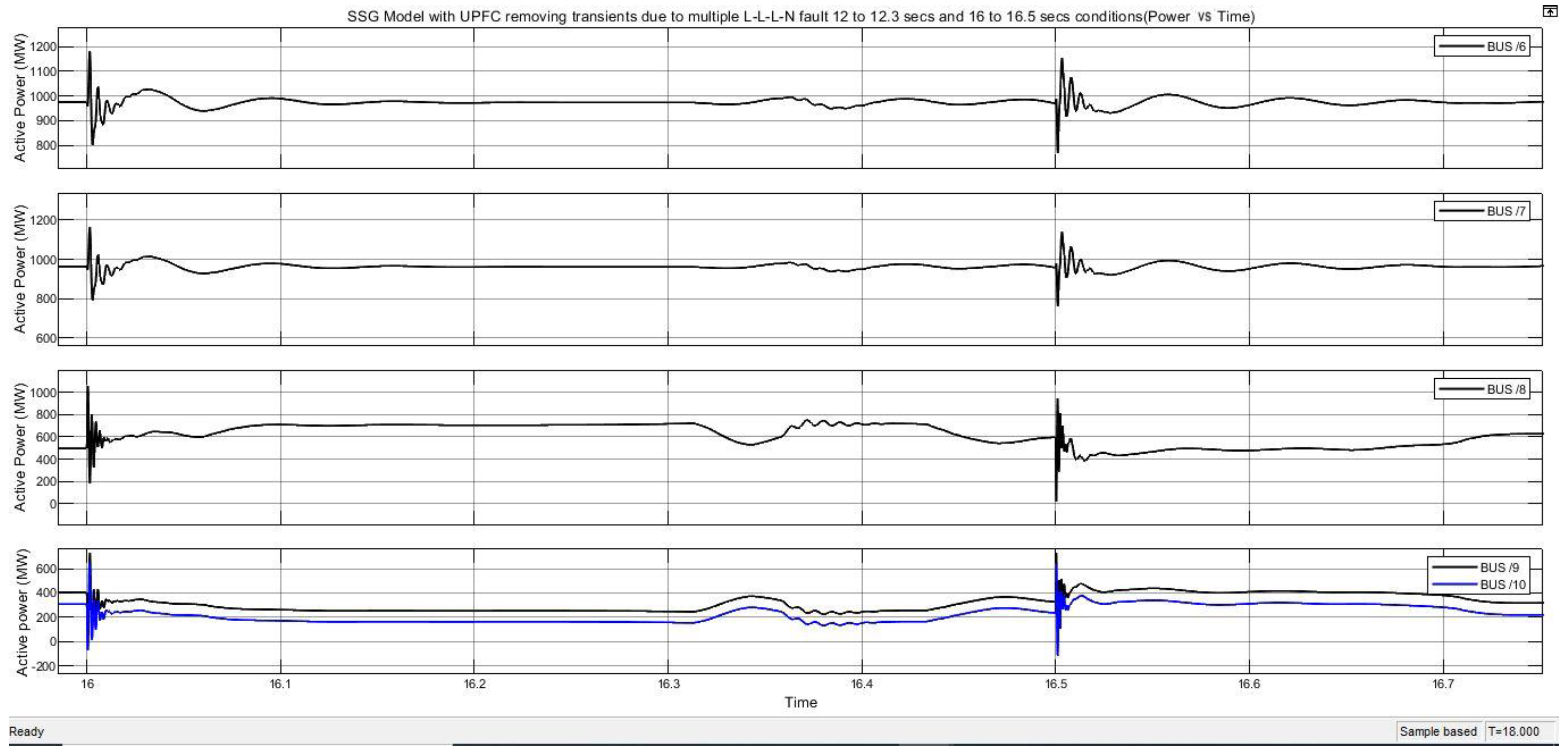
7.7. Case 7. By Incorporation of UPFC, and Multiple L-L-L-N Faults Are Also Injected
8. Conclusions and Future Research
- Upgrading the SSGs in terms of their protection and monitoring using various control protocols on a periodic basis to increase the network’s reliability;
- Considering more than two clusters and performing their transmission network analysis on the DIG silent power factory;
- Utilizing more than one UPFC and their impact on the SSGs and operating the power system network and the study on cascading failures due to N-1 contingencies and its techniques;
- Additionally, a pre-disturbance systems study will be performed, taking into account the potential for catastrophic events.
Author Contributions
Funding
Acknowledgments
Conflicts of Interest
References
- Tariq, M.; Poor, H.V. Electricity Theft Detection and Localization in Grid-tied Microgrids. IEEE Trans. Smart Grid 2018, 9, 1920–1929. [Google Scholar] [CrossRef]
- Sato, T.; Kammen, D.M.; Duan, B.; Macuha, M.; Zhou, Z.; Wu, J.; Tariq, M.; Asfaw, S.A. Smart Grid Standards: Specifications, Requirements, and Technologies; John Wiley & Sons: Hoboken, NJ, USA, 2015; pp. 379–393. [Google Scholar]
- Adnan, M.; Tariq, M.; Zhou, Z.; Poor, H.V. Load flow balancing and transient stability analysis in renewable integrated power grids. Int. J. Electr. Power Energy Syst. 2018, 104, 744–771. [Google Scholar] [CrossRef]
- Saeedreza, J.; Badihi, H.; Zhang, Y. Passive fault-tolerant control strategies for power converter in a hybrid microgrid. Energies 2020, 13, 5625. [Google Scholar]
- Mehdi, H.; Salmasi, F.R. Fault-tolerant supervisory controller for a hybrid AC/DC micro-grid. IEEE Trans. Smart Grid 2016, 9, 2809–2823. [Google Scholar]
- Chan, J.C.L.; Lee, T.H. Sliding mode observer-based fault-tolerant secondary control of microgrids. Electronics 2020, 9, 1417. [Google Scholar] [CrossRef]
- Ali, M.; Adnan, M.; Tariq, M. Optimum control strategies for short term load forecasting in smart grids. Int. J. Electr. Power Energy Syst. 2019, 113, 792–806. [Google Scholar] [CrossRef]
- Khan, N.H.; Wang, Y.; Tian, D.; Jamal, R.; Ebeed, M.; Deng, Q. Fractional PSOGSA Algorithm Approach to Solve Optimal Reactive Power Dispatch Problems with Uncertainty of Renewable Energy Resources. IEEE Access 2020, 8, 215399–215413. [Google Scholar] [CrossRef]
- Youssef, K.H.; Abouelenin, F.M. Analysis of simultaneous unbalanced short circuit and open conductor faults in power systems with transposed lines and six-phase sections. Alex. Eng. J. 2016, 553, 69–377. [Google Scholar]
- Novak, M.; Kravec, R.; Kanalik, M.; Conka, Z.; Kolcun, M. UPFC influence to transient stability of power system. In Proceedings of the 2014 ELEKTRO, Rajecke Teplice, Slovakia, 19–20 May 2014; pp. 343–346. [Google Scholar] [CrossRef]
- Liu, Y.; Sun, K.; Yao, R.; Wang, B. Power system time domain simulation using a differential transformation method. IEEE Trans. Power Syst. 2019, 34, 3739–3748. [Google Scholar] [CrossRef]
- Jafarzadeh, S.; Genc, I.; Nehorai, A. Real-time transient stability prediction and coherency identification in power systems using Koopman mode analysis. Electr. Power Syst. Res. 2021, 201, 107565. [Google Scholar] [CrossRef]
- Wang, L.; Li, H.-W.; Wu, C.-T. Stability analysis of an integrated offshore wind and seashore wavefarmfed to a power grid using a unified power flow controller. IEEE Trans. Power Syst. 2013, 28, 2211–2221. [Google Scholar] [CrossRef]
- Gholipour, E.; Saadate, S. Improving of transient stability of power systems using UPFC. IEEE Trans. Power Deliv. 2005, 20, 1677–1682. [Google Scholar] [CrossRef]
- Gholipour, E.; Saadate, S. A new method for improving transient stability of power systems by using UPFC. In Proceedings of the European Power Electronics, Toulouse, France, 2–4 September 2003. [Google Scholar]
- Canizares, C.A. Power flow and transient stability models of FACTS controllers for voltage and angle stability studies. In Proceedings of the IEEE Power Engineering Society Winter Meeting, Singapore, 23–27 January 2000; Volume 2, pp. 1447–1452. [Google Scholar]
- Laufenberg, M.; Pai, M. A new approach to dynamic security assessment using trajectory sensitivities. IEEE Trans. Power Syst. 1998, 13, 953–958. [Google Scholar] [CrossRef]
- Nguyen, T.B. Dynamic Security Assessment of Power Systems using Trajectory Sensitivity Approach. Doctoral Dissertation, University of Illinois, Champaign, IL, USA, 2002. [Google Scholar]
- Rodriguez, J.; Lai, J.S.; Peng, F.Z. Multilevel inverters: A survey of topologies, controls and applications. IEEE Trans. Ind. Electron. 2002, 49, 724e38. [Google Scholar] [CrossRef] [Green Version]
- Papic, I. Mathematical analysis of FACTS devices based on a voltage source converter, part II: Steady state operational characteristics. Electr. Power Syst. Res. 2000, 56, 149e57. [Google Scholar] [CrossRef]
- Kannan, S.; Jayaram, S.; Salama, M.M.A. Real and reactive power coordination for a Unified Power Flow Controller. IEEE Trans. Power Syst. 2004, 19, 1454–1461. [Google Scholar] [CrossRef]
- Nabavi-Niaki, A.; Iravani, M.R. Steady-state and dynamic models of unified power flow controller (UPFC) for power system studies. IEEE Trans. Power Syst. 1996, 11, 1937–1943. [Google Scholar] [CrossRef]
- El Saeed, A.; Tantawi, M.; Youssef, K. Power quality phenomena in academic building. In Proceedings of the IEEE Porto Power Tech Proceedings, Porto, Portugal, 10–13 September 2001. [Google Scholar]
- Bollen, M.H.J. Understanding Power Quality Problems: Voltage Sags and Interruptions; Power Engineering Series; IEEE: Piscataway, NJ, USA, 2000. [Google Scholar]
- Dou, C.; Yang, J.; Bo, Z.; Bi, Y.; Gui, T.; Li, X. Decentralized coordinated robust controller design for multimachine power system based on multi-agent system. In Proceedings of the 11th IET International Conference on developments in Power Systems Protection, Birmingham, UK, 23–26 April 2012. [Google Scholar]
- Abood, A.A.; Avakian, S.K.; Abdalla, A.N. The application of multi-agent technology on transient stability assessment of Iraqi super grid network. Am. J. Appl. Sci. 2008, 5, 1494–1498. [Google Scholar] [CrossRef] [Green Version]
- Tariq, M.; Adnan, M. Stabilizing Super Smart Grids Using V2G: A Probabilistic Analysis. In Proceedings of the 2019 IEEE 89th Vehicular Technology Conference (VTC2019-Spring), Kuala Lumpur, Malaysia, 28 April–1 May 2019; pp. 1–5. [Google Scholar] [CrossRef]
- Tariq, M.; Adnan, M.; Srivastava, G.; Poor, H.V. Instability Detection and Prevention in Smart Grids Under Asymmetric Faults. IEEE Trans. Ind. Appl. 2020, 56, 4510–4520. [Google Scholar] [CrossRef]
- Huang, T.; Wang, J. A practical method of transient stability analysis of stochastic power systems based on EEAC. Int. J. Electr. Power Energy Syst. 2019, 107, 167–176. [Google Scholar] [CrossRef]
- Li, M.; Pal, A.; Phadke, A.G.; Thorp, J.S. Transient stability prediction based on apparent impedance trajectory recorded by PMUs. Int. J. Electr. Power Energy Syst. 2014, 54, 498–504. [Google Scholar] [CrossRef]
- Farantatos, E.; Huang, R.; Cokkinides, G.J.; Meliopoulos, A.P. A predictive generator out-of-step protection and transient stability monitoring scheme enabled by a distributed dynamic state estimator. IEEE Trans. Power Deliv. 2015, 31, 1826–1835. [Google Scholar] [CrossRef]
- Rahman, M.S.; Pota, H.R.; Orchi, T.F. A multi-agent approach for enhancing transient stability of smart grids with renewable energy. In Proceedings of the 2013 Australasian Universities Power Engineering Conference (AUPEC), Hobart, TAS, Australia, 29 September–3 October 2013; pp. 1–6. Available online: https://www.aconf.org/conf_35795/photo.html (accessed on 30 August 2022). [CrossRef]
- Chatterjee, D.; Ghosh, A. Transient stability assessment of power systems containing series and shunt compensators. IEEE Trans. Power Eng. 2007, 22, 1210–1220. [Google Scholar] [CrossRef] [Green Version]
- Mohamed, M.A.; Karady, G.G.; Yousuf, A.M. New strategy agents to improve power system transient stability. World Acad. Sci. Eng. Technol. 2007, 3, 678–683. [Google Scholar]
- Karady, G.; Daoud, A.; Mohamed, M. On-line transient stability enhancement using multi-agent technique. IEEE Power Eng. Soc. Winter Meet. 2002, 2, 893–899. [Google Scholar]
- Karady, G.; Mohamed, M. Improving transient stability using fast valving based on tracking rotor-angle and active power. In Proceedings of the IEEE Power Engineering Society Summer Meeting, Chicago, IL, USA, 21–25 July 2002; Volume 3, pp. 1576–1581. [Google Scholar] [CrossRef]
- Hadidi, R.; Jeyasurya, B. A real-time multiagent wide-area stabilizing control framework for power system transient stability enhancement. In Proceedings of the IEEE Power Engineering Society General Meeting, Denver, CO, USA, 17–21 July 2011; pp. 1–8. [Google Scholar]
- Ahmad, N.; Ghadi, Y.; Adnan, M.; Ali, M. Load Forecasting Techniques for Power System: Research Challenges and Survey. IEEE Access 2022, 10, 71054–71090. [Google Scholar] [CrossRef]
- Tariq, M.; Adnan, M. Load flow balancing and transient stability analysis in super smart girds using V2G. In Proceedings of the 2018 IEEE Power Energy Society Innovative Smart Grid Technologies Conference (ISGT), Washington, DC, USA, 19–22 February 2018. [Google Scholar]
- Adnan, M.; Ali, M.; Basalamah, A.; Tariq, M. Preventing Cascading Failure Through Fuzzy Co-Operative Control Mechanism Using V2G. IEEE Access 2019, 7, 142607–142622. [Google Scholar] [CrossRef]
- Liaqat, M.; Khan, M.G.; Fazal, M.R.; Ghadi, Y.; Adnan, M. Multi-Criteria Storage Selection Model for Grid-Connected Photovoltaics Systems. IEEE Access 2021, 9, 115506–115522. [Google Scholar] [CrossRef]
- Liaqat, M.; Ghadi, Y.; Adnan, M. Multi-Objective Optimal Power Sharing Model for Futuristic SAARC Super Smart Grids. IEEE Access 2022, 10, 328–351. [Google Scholar] [CrossRef]
- Adnan, M.; Ali, M.; Tariq, M. A Probabilistic Approach For Power Network Stability in Smart Grids. In Proceedings of the 2019 15th International Conference on Emerging Technologies (ICET), Peshawar, Pakistan, 2–3 December 2019; pp. 8138–8143. [Google Scholar] [CrossRef]
- Shahbaz, M.H.; Amin, A.A. A Review of Classical and Modern Control Techniques Utilized in Modern Microgrids. Recent Adv. Electr. Electron. Eng. 2021, 14, 459–472. [Google Scholar] [CrossRef]
- Ebrahimpour, R.; Abharian, E.K.; Birjandi, A.A.M.; ZeinolabedinMoussavi, S. Transient Stability Assessment of a Power System with a UPFC by Mixture of Experts. Int. J. Comput. Electr. Eng. 2010, 2, 643–648. [Google Scholar] [CrossRef] [Green Version]
- Kundur, P.; Malik, O. Power System Stability and Control; McGraw-Hill: New York, NY, USA, 1994. [Google Scholar]
- Pota, H.R.; Dong, Y. Recent development in direct assessment of transient stability limit. Electr. Energy Conf. 1990, 134–138. Available online: https://search.informit.org/doi/10.3316/INFORMIT.608906274959883 (accessed on 30 August 2022).
- Ayar, M.; Obuz, S.; Trevizan, R.D.; Bretas, A.S.; Latchman, H.A. A Distributed Control Approach for Enhancing Smart Grid Transient Stability and Resilience. IEEE Trans. Smart Grid 2017, 8, 3035–3044. [Google Scholar] [CrossRef]
- Vijayan, J. Stuxnet renews power grid security concerns. Comput. World 2010, 26. Available online: https://www.computerworld.com/article/2519574/stuxnet-renews-power-grid-security-concerns.html (accessed on 30 August 2022).
- Lee, R.M.; Assante, M.J.; Conway, T. Analysis of the cyber-attack on the Ukrainian power grid. SANS Ind. Control. Syst. 2016, 388, 1–29. [Google Scholar]
- Office of Electricity Delivery and Energy Reliability. Advancement of Synchro Phasor Technology in Projects Funded by the American; Technical Report No. Available online: https://www.energy.gov/sites/default/files/2019/12/f70/Advancement%20of%20Synchrophasor%20Technology%20Report%20March%202016.pdf (accessed on 30 August 2022).
- Karimi, A.; Feliachi, A. Decentralized adaptive back stepping control of electric power systems. Electr. Power Syst. Res. 2008, 78, 484–493. [Google Scholar] [CrossRef]
- Nur Asyik, H.; Zahir, J.P.; Akhtar, K. Impact of distributed generation on smart grid transient stability. Smart Grid Renew. Energy 2011, 2, 99–109. [Google Scholar]
- Rajabi-Ghahnavieh, A.; Fotuhi-Firuzabad, M.; Shahidehpour, M.; Feuillet, R. UPFC for enhancing power system reliability. IEEE Trans. Power Deliv. 2010, 25, 2881–2890. [Google Scholar] [CrossRef]
- Mihalic, R.; Zunko, P.; Povh, D. Improvement of transient stability using unified power flow controller. IEEE Trans. Power Deliv. 1996, 11, 485–492. [Google Scholar] [CrossRef]
- Qader, M. Design and simulation of a different innovation controller-based UPFC (unified power flow controller) for the enhancement of power quality. Energy 2015, 89, 576–592. [Google Scholar] [CrossRef]
- Aghaei, J.; Zarei, M.; Asban, M.; Ghavidel, S.; Heidari, A.; Agelidis, V.G. Determining potential stability enhancements of flexible AC transmission system devices using corrected transient energy function. IET Gener. Transm. Distrib. 2016, 10, 470–476. [Google Scholar] [CrossRef]
- Sullivan, D.; Mader, D. Fundamentals and Characteristics of Dynamic Reactive Power Control. In Proceedings of the IEEE PESWebinar, 18 December 2018; Available online: https://resourcecenter.ieee-pes.org/education/webinars/PESVIDWEBGPS0016.html (accessed on 25 September 2022).
- IEEE. IEEE Approved Draft Guide for the functional Specifications for Transmission Static Synchronous Compensator (STATCOM) Systems; IEEE: Piscataway, NJ, USA, 2018. [Google Scholar]
- IEEE. IEEE Guide for the Functional Specification of Transmission Static Var Compensators; IEEE: Piscataway, NJ, USA, 2011. [Google Scholar]
- Lannoye, E.; Flynn, D.; O’Malley, M. Transmission, variable generation and power system flexibility. IEEE Trans. Power Syst. 2015, 30, 57–66. [Google Scholar] [CrossRef]
- Refaat, S.S.; Abu-Rub, H.; Sanfilippo, A.P.; Mohamed, A. Impact of grid-tied large-scale photovoltaic system on dynamic voltage stability of electric power grids. IET Renew. Power Gener. 2018, 12, 157–164. [Google Scholar] [CrossRef]
- Cong, L.; Wang, Y. Co-ordinated control of generator excitation and STATCOM for rotor angle stability and voltage regulation enhancement of power systems. IEE Proc. Gener. Transm. Distrib. 2002, 149, 659–666. [Google Scholar] [CrossRef]
- Esparza, A.; Segundo, J.; Nunez, C.; Visairo, N.; Barocio, E.; Garcia, H. Transient stability enhancement using a wide-area controlled SVC: An HIL validation approach. Energies 2018, 11, 1639. [Google Scholar] [CrossRef] [Green Version]
- Kanchanaharuthai, A.; Chankong, V.; Loparo, K.A. Transient stability and voltage regulation in multimachine power systems vis-a-vis STATCOM and battery energy storage. IEEE Trans. Power Syst. 2015, 30, 2404–2416. [Google Scholar] [CrossRef]
- Adnan, M.; Israr, A.; Khan, N.; Irfan, M. A generic scenario of a load flow study in saarc countries super grid using high voltage alternating current (hvac) and high voltage direct current (hvdc). Int. J. Sci. Eng. Res. 2016, 7, 210–223. [Google Scholar]
- Movahedi, A.; Niasar, A.H.; Gharehpetian, G.B. Designing SSSC, TCSC, and STATCOM controllers using AVURPSO, GSA, and GA for transient stability improvement of a multi-machine power system with PV and wind farms. Int. J. Electr. Power Energy Syst. 2019, 106, 455–466. [Google Scholar] [CrossRef]
- Vittal, V.; Zhou, E.; Hwang, C.; Fouad, A.A. Derivation of stability limits using analytical sensitivity of the transient energy margin. IEEE Trans. Power Syst. 1989, 4, 1363–1372. [Google Scholar] [CrossRef]
- Shubhanga, K.N.; Kulkarni, A.M. Application of structure preserving energy margin sensitivity to determine the effectiveness of shunt and series FACTS devices. IEEE Trans. Power Syst. 2002, 17, 730–738. [Google Scholar] [CrossRef]
- Padiyar, K.; Devi, A.L. Control and simulation of static condenser. In Proceedings of the 9th Annual Applied Power Electronics Conference and Exposition, Orlando, FL, USA, 13–17 February 1994. [Google Scholar]
- Padiyar, K.; Rao, K.U. Discrete control of TCSC for stability improvement in power systems. In Proceedings of the 4th IEEE Conference Control Applications, Albany, NY, USA, 28–29 September 1995. [Google Scholar]
- Hingorani, N.G.; Gyugyi, L. Understanding FACTS; Standard Publishers Distributors: Delhi, India, 2001. [Google Scholar]
- Yousaf, S.; Mughees, A.; Khan, M.G.; Amin, A.A.; Adnan, M. A Comparative Analysis of Various Controller Techniques for Optimal Control of Smart Nano-Grid Using GA and PSO Algorithms. IEEE Access 2020, 8, 205696–205711. [Google Scholar] [CrossRef]
- Kumar, N.S.; Gokulakrishnan, J. Impact of facts controllers on the stability of power systems connected with doubly fed induction generators. Int. J. Electr. Power Energy Syst. 2011, 33, 1172–1184. [Google Scholar] [CrossRef]
- Guo, J.; Crow, M.; Sarangapani, J. An improved UPFC control for oscillation damping. IEEE Trans. Power Syst. 2009, 24, 288–296. [Google Scholar] [CrossRef]
- Zhang, S.; Zhu, Z.; Li, Y. A Critical Review of Data-Driven Transient Stability Assessment of Power Systems: Principles, Prospects and Challenges. Energies 2021, 14, 7238. [Google Scholar] [CrossRef]
- Abdelouahed, T.; Ahmed, Z.S. Modeling and transient simulation of unified power ow controllers UPFC in power system. In Proceedings of the 2015 4th International Conference on Electrical Engineering (ICEE), Boumerdes, Algeria, 13–15 December 2015; pp. 1–7. [Google Scholar]
- Chowdhury, M.S.R.; Howlader, M.M.; Hasan, A.K.M.K.; Ferdaus, M.R. Distinctive study of UPFC and fault analysis under simulated environment. In Proceedings of the 2015 Third International Conference on Technological Advances in Electrical, Electronics and Computer Engineering (TAEECE), Beirut, Lebanonpp, 29 April–1 May 2015; pp. 251–255. [Google Scholar]
- Moravej, Z.; Pazoki, M.; Khederzadeh, M. New pattern-recognition method for fault analysis in transmission line with UPFC. IEEE Transactions on Power Delivery. IEEE Trans. Power Deliv. 2015, 30, 1231–1242. [Google Scholar] [CrossRef]
- Pai, M.A. Transient Stability of Power System; Kluwer Academic Publishers: Norwell, MA, USA, 2000. [Google Scholar]
- Salim, R.; Oleskovicz, M.; Ramos, R. Power quality of distributed generation systems as affected by electromechanical oscillations-definitions and possible solutions. IET Gener. Transm. Distrib. 2011, 5, 1114–1123. [Google Scholar] [CrossRef]
- Adnan, M.; Khan, M.G.; Amin, A.A.; Fazal, M.R.; Tan, W.-S.; Ali, M. Cascading Failures Assessment in Renewable Integrated Power Grids Under Multiple Faults Contingencies. IEEE Access 2021, 9, 82272–82287. [Google Scholar] [CrossRef]


| Method | Function | Advantage | Drawback |
|---|---|---|---|
| Data-driven | The stability status of the system is analyzed by the transient stability assessment model | Fast speed for the calculation is used and a strong learning ability | Poor adaptability and representation to the topological changes |
| Direct method | Energy function implementation to judge and enhance the transient stability | The speed of calculation is high and enough margin for the stability | Difficulty in energy function and the result calculation is conservative. |
| Time-domain simulation-based | The system’s dynamic processes are defined by algebraic and differential equations | Scalability is good and accurate results | The accuracy of the system can be affected by the results of the calculation |
Publisher’s Note: MDPI stays neutral with regard to jurisdictional claims in published maps and institutional affiliations. |
© 2022 by the authors. Licensee MDPI, Basel, Switzerland. This article is an open access article distributed under the terms and conditions of the Creative Commons Attribution (CC BY) license (https://creativecommons.org/licenses/by/4.0/).
Share and Cite
Alsuwian, T.; Basit, A.; Amin, A.A.; Adnan, M.; Ali, M. An Optimal Control Approach for Enhancing Transients Stability and Resilience in Super Smart Grids. Electronics 2022, 11, 3236. https://doi.org/10.3390/electronics11193236
Alsuwian T, Basit A, Amin AA, Adnan M, Ali M. An Optimal Control Approach for Enhancing Transients Stability and Resilience in Super Smart Grids. Electronics. 2022; 11(19):3236. https://doi.org/10.3390/electronics11193236
Chicago/Turabian StyleAlsuwian, Turki, Abdul Basit, Arslan Ahmed Amin, Muhammad Adnan, and Mansoor Ali. 2022. "An Optimal Control Approach for Enhancing Transients Stability and Resilience in Super Smart Grids" Electronics 11, no. 19: 3236. https://doi.org/10.3390/electronics11193236