Article

Strain Modulation of Microstructure, Magnetic Domains, and Magnetic Properties of Ti/Fe/Ni81Fe19/Fe/Ti Multilayer Thin Films

1
School of Materials and Energy, University of Electronic Science and Technology of China, Chengdu 610054, China
2
Hengdian Group DMEGC Magnetics Company, Ltd., Jinhua 322118, China
3
Guangdong EXSENSE Electronics Technology Company, Ltd., Zhaoqing 526000, China
*
Author to whom correspondence should be addressed.
Coatings 2023, 13(2), 363; https://doi.org/10.3390/coatings13020363
Submission received: 6 January 2023 / Revised: 1 February 2023 / Accepted: 3 February 2023 / Published: 5 February 2023

Abstract

:
A simple and convenient method is demonstrated in this work by continuously applying uniaxial tensile strains to tune the high-frequency properties of flexible magnetic films. The magnetostriction effect causes the uniaxial magnetic anisotropy in the Ti/Fe/Ni81Fe19/Fe/Ti multilayer film when the flexible substrate transitions from the convex state to the planar state after preparation. In addition, the microstructure, magnetic domain morphology, and the high-frequency magnetic performance of the pre-strained Ti/Fe/Ni81Fe19/Fe/Ti multilayer films are investigated. The results show that the flexible Ti/Fe/Ni81Fe19/Fe/Ti multilayer films’ initial permeability can be monotonically varied over a hundred units, and the resonant frequency can be adjusted around 1.5 GHz. The flexible Ti/Fe/Ni81Fe19/Fe/Ti films, with their elastic-tunable magnetic performance, are promising candidate materials for flexible microwave devices.

1. Introduction

Microwave magnetic devices are indispensable components in satellite and mobile communications systems [1,2,3,4,5,6]. The demand for microwave devices such as higher integration, higher operating frequency, and smaller size is an important reflection of the rapid development of the electronic communication industry [7,8,9]. There is a significant demand to improve the performance of magnetoelectronic units, which are the core components of microwave devices. Further study of the relationship between the magnetic domain structure and the microscopic results of soft magnetic films in the origin of magnetic behavior is an important prerequisite for optimizing magnetic properties [10,11,12,13]. In previous studies, most of the magnetic films used in microwave devices were prepared using traditional rigid substrates such as silicon and glass [14,15,16]. High-frequency microwave magnetic devices are applied to reconfigurable electromagnetic interference shielding and wearable wireless transmission systems, and have been used in the development of flexible substrates. These are the embodiment of the popularity of flexible electronic technology in recent years [17,18]. The flexible high-frequency devices usually show good mechanical strain adjustability [19,20,21,22]. Recently, Tang et al. reported amorphous CoFeB films deposited on flexible polyethylene terephthalate (PET) substrates and the magneto-mechanical coupling effect was studied [23]. Liu et al. fabricated flexible CoFeB films grown on pre-strained polydimethylsiloxane, and the high-frequency characteristics of the film were adjusted by changing the applied pre-strain [24]. Flexible magnetic thin films and spintronic devices grown on plastic substrates are conformable, attracting extensive attention. However, the external strain caused by mechanical deformation can significantly change the magnetic anisotropy due to the magnetostriction effect for magnetic thin films deposited on flexible substrates, [25]. Previous works have shown that strain deposition is one of the simplest and most effective methods to adjust the resonance frequency (fr) of magnetic films [25]. Thin films deposited on flexible substrates are useful in stretchable magnetoelectronics and high-frequency electromagnetic devices due to their strain sensitivity. For practical applications, such as microwave filters and inductors, the fr is related to strain-induced magnetic anisotropy [26]. In addition, the ability to generate adjustable anisotropy through pre-strain from the flexible substrate bending can eliminate the complex in situ annealing process and clamping effect of the rigid substrate. Therefore, the magnetostrictive thin films deposited on flexible substrates are suitable for studying the relationship between magnetism and external strain. The high-frequency characteristics of magnetic thin films’ can be easily tuned by pre-stretching strain.
In this study, we prepared flexible soft magnetic films on PET using a self-made bending die and pre-stretching elastic substrate. The permalloys for changing the anisotropic field Hk is preferred. Fe and Ni81Fe19 thin films were deposited on pre-stretched elastomeric substrates by electron beam evaporation. The evolution of magnetic anisotropy with microstructure was studied. It is important to establish the relationship between magnetic anisotropy, texture formation, magnetization reversal, and external strains. The continuous tunability of magnetic films’ fr may pave the way for creating devices with mechanically adjustable resonance frequencies suitable for various frequency-based applications.

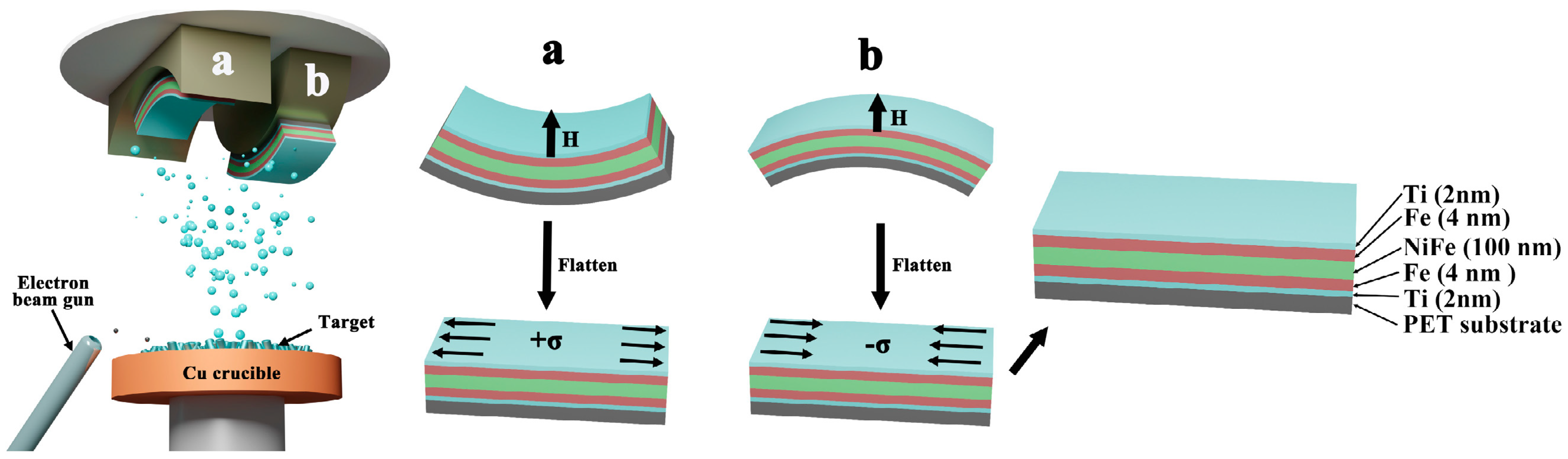
2. Experimental Details

The TFNFT magnetic film consists of Ti/Fe/Ni81Fe19/Fe/Ti films having a thickness of 2 nm /4 nm/100 nm/4 nm/2 nm, respectively, deposited on the PET flexible substrates using the electron beam evaporation (EB-500). The magnetic anisotropy was controlled by regulating the radius of curvature during the deposition. Figure 1 shows a schematic diagram of the strain induced by bending the flexible PET substrate. Six bases with different curvature were prepared to produce different compressive and tensile strains (ε = −0.26%, ε = −0.52%, ε = −0.78%, ε = 0.26%, ε = 0.52%, ε = 0.78%). Then, different flexible substrates were pasted on the convex mold and the concave mold so that different bending stresses were introduced into the film sample through the flexible substrate. The induced stress on the TFNFT films can be calculated by Hooke’s law, which describes the strain–stress relationship in the film.
The surface morphology, surface roughness, and average grain size of the PET/TFNFT multilayer films were investigated and calculated by atomic force microscopy (AFM, Bruker MultiMode8, Bruker, Billerica, MA, USA), and its scanning area was 2 × 2 μm2. The hysteresis loop, coercivity distribution, and magnetic film interaction of the samples were measured by using a vibrating sample magnetometer (VSM, Lake Shore 8604, Lake Shore Cryotronics, Inc., Westerville, OH, USA). Magneto-optical Kerr microscopy (MOKE, Evico Magnetics GmbH, Em-Kerr-Highres, Dresden, Germany) was used to study the domain wall displacement and magnetic domain morphology of the samples. The longitudinal Kerr effect was used to observe the magnetic domain structure. The permeability spectra were obtained using the one port short-circuit microstrip transmission line perturbation method and an Agilent network analyzer (PNA, N5227A, Keysight, Santa Rosa, CA, USA) in the frequency range of 0.1–4 GHz [27].

3. Results and Discussion

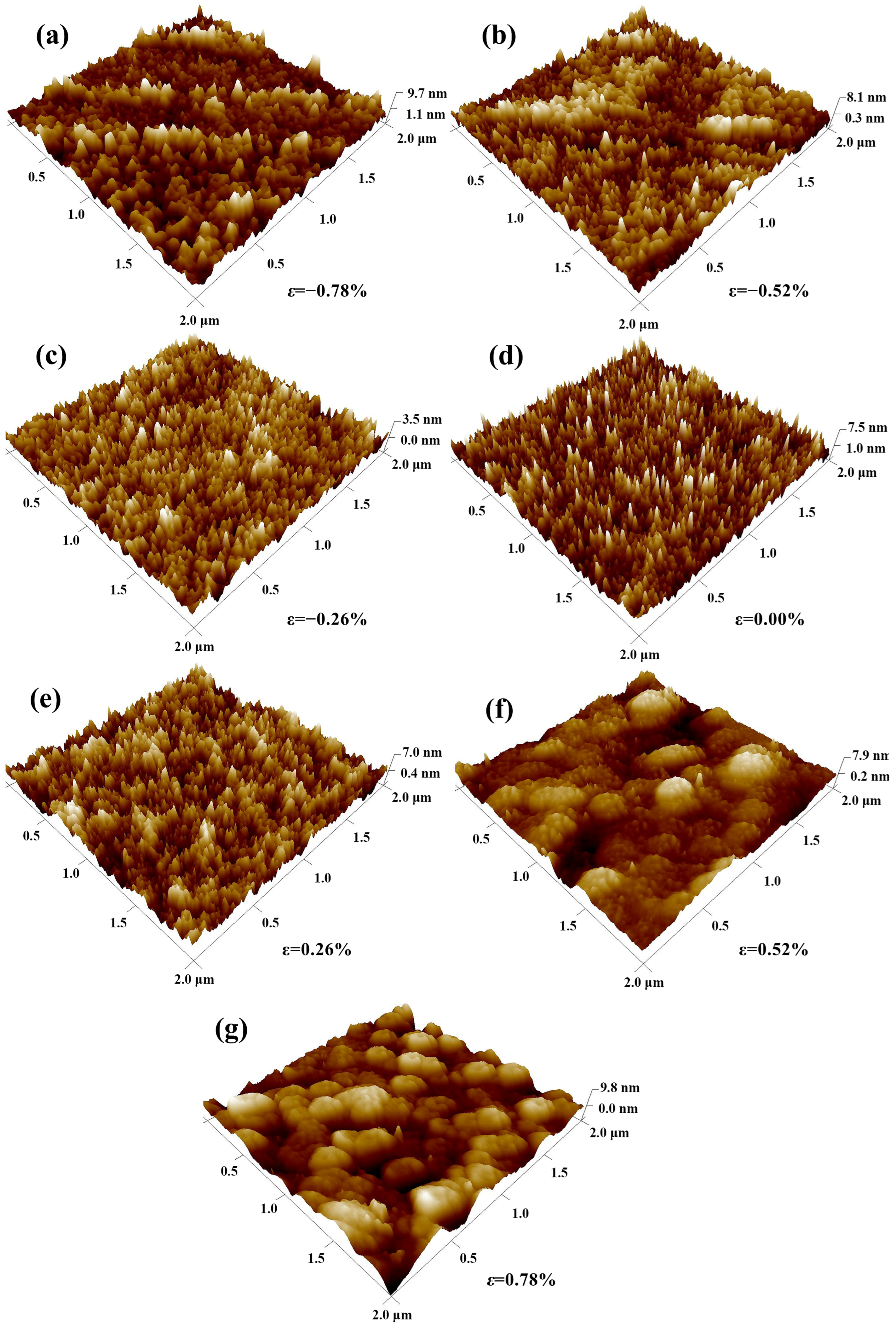
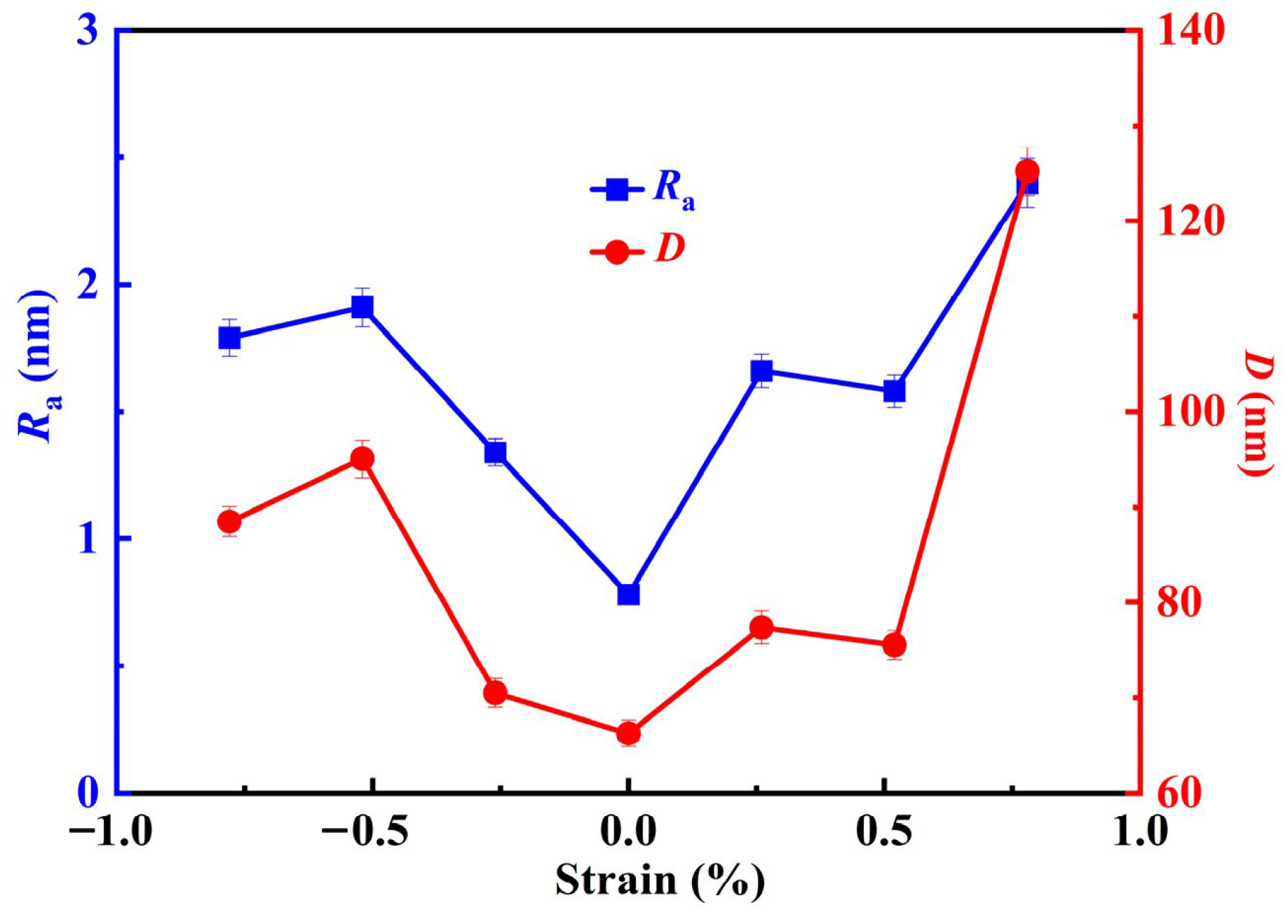
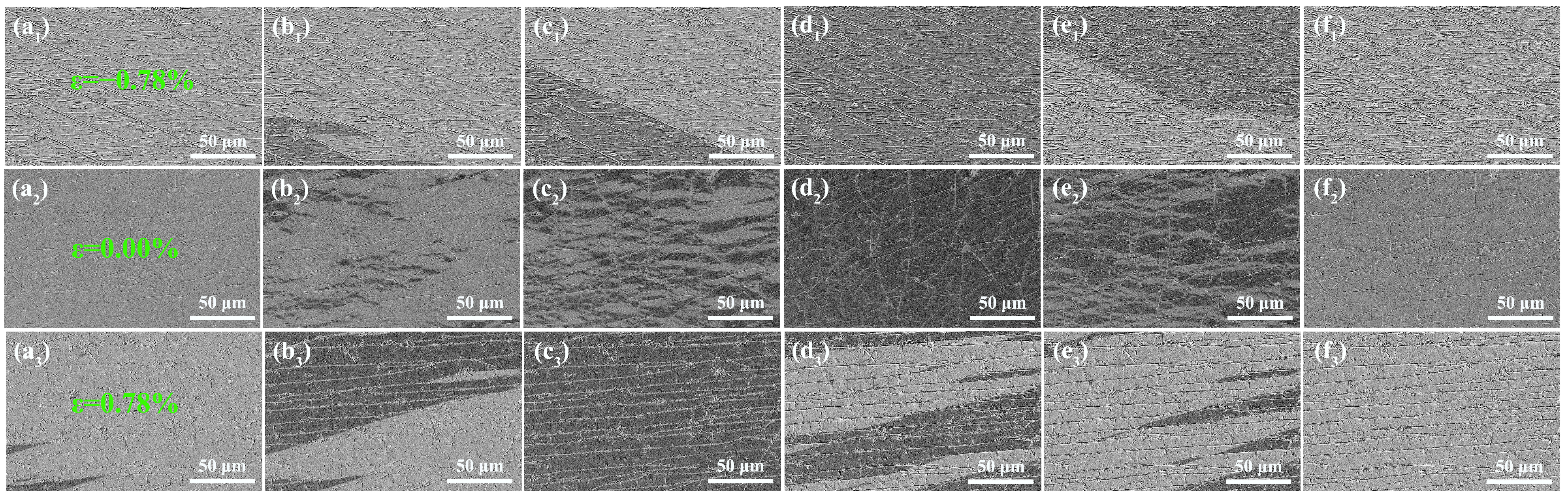
3.1. Surface Morphology Analysis

The AFM images of the TFNFT multilayer films deposited on PET substrates at various external strains are shown in Figure 2. The surface morphology’s evolution reflects the growth mode change under different strains. Figure 2d shows the surface topography for the TFNFT multilayer films without external strain, which has excellent uniformity and a relatively smooth surface. When the strain is relatively small, as shown in Figure 2c,e, the grain grows vertically, improving the densification and uniformity. When the compressive strain increases, as shown in Figure 2d–g, the film’s surface morphology changes from a flat needle to a valley pile shape. Due to the tensile stress and compressive stress, different surface morphologies are formed. The magnetic moment distribution in the film varies with the surface morphology. The Ra and D of the film are calculated from the AFM images, as shown in Figure 3. When the compressive strain is changed from ε = 0 to ε = −0.78%, the D increases from 66 nm to 88 nm. However, when the tensile strain is changed from ε = 0 to ε = 0.78%, the D increases, and large particles appear on the film surface. It is clear that the Ra of the TFNFT multilayer films first decreases and then increases with strain. With the strain from ε = −0.78% to ε = 0.78%, the Ra of TFNFT multilayer films are 1.79 nm, 1.91 nm, 1.34 nm, 0.78 nm, 1.66 nm, 1.58 nm, and 2.41 nm. The reason may be that with increasing strain, the Ra decreases slightly at the beginning of growth due to the difference in growth mode, where the film is smooth in the absence of strain. When the tensile and compressive strains increase, the microdefects increase, increasing Ra and D. The difference in average grain size and surface morphology is caused by the restoration of the flexible substrate from the arc surface with a different radius of curvature. Therefore, the microscopic morphology of TFNFT multilayer films may change due to the diffusion mechanism or local overheating, which is not surprising for a polymer substrate, because of its low thermal conductivity [28].

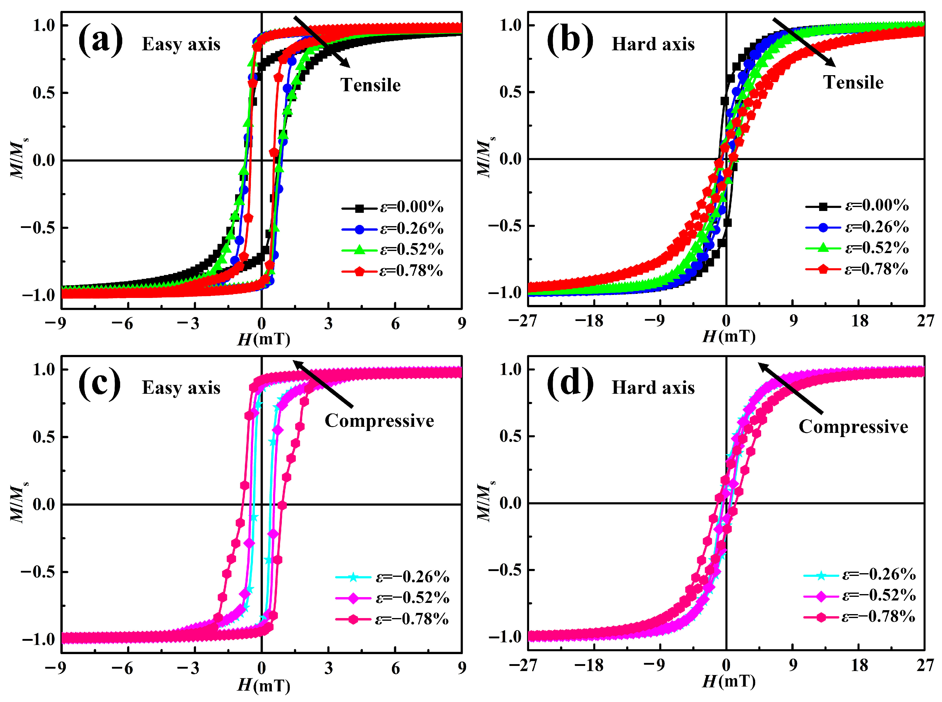
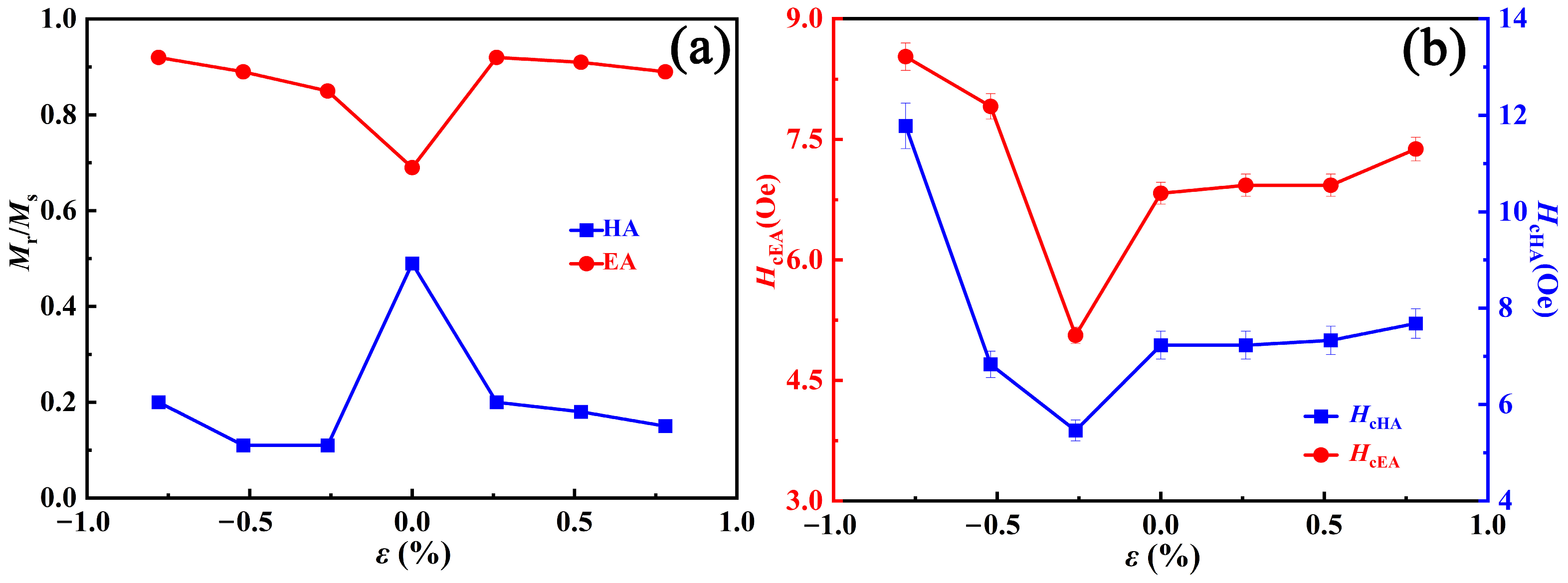
3.2. Static Magnetic Property

The magnetization (M)-magnetic field (H) hysteresis loops are measured along both the easy axis (EA) and the hard axis (HA) in the plane of the TFNFT multilayer films grown on flexible PET substrates, to investigate their magnetic properties. Figure 4 shows the in-plane magnetic hysteresis loops of the TFNFT multilayer films at various strains. In-plane measurements are mainly the characteristic of the in-plane uniaxial magnetic anisotropy. As shown in Figure 4, the magnetic hysteresis loops along the EA are rectangular in shape, while those along the HA are sheared. The coercivity (Hc) and the remanence ratio Mr/Ms along the EA and HA obtained from Figure 4 are shown in Figure 5. The remanence ratio Mr/Ms of the hysteresis loop measured along the EA increases from 0.69 to 0.92 as the tensile strain increases from ε = 0 to ε = 0.78%, while the remanence ratio Mr/Ms of the hysteresis loop measured along the EA increases from 0.69 to 0.89 as the compressive strain changes from ε = 0 to ε = −0.78%, indicating that the magnetic moments are transversely aligned under both tensile and compressive strains. Due to the enhanced uniaxial anisotropy, the coercivity field Hc measured along the EA increases from 5 Oe to 9 Oe, while the coercivity field Hc for the tensile strain increases correspondingly from 6.83 to 7.38. For the hysteresis loop measured along the HA, the value of Mr/Ms decreases sharply from 0.49 to 0.20 and Hc increases from 7 Oe to 12 Oe with increasing compressive strain from ε = 0% to ε = −0.78%. In contrast, the value of Mr/Ms decreases sharply from 0.49 to 0.15 and Hc increases from 7 Oe to 8 Oe with increasing tensile strain from ε = 0% to ε = 0.78%. It follows that the EA of the film can be tuned to the HA by applying tensile strain in the hard magnetization direction or compressive strain in the easy magnetization direction of the film. Conversely, the HA of the film can be tuned to the EA. Therefore, the magnetic anisotropy of the film can be effectively regulated by strain. The distinctive features of uniaxial magnetic anisotropy are most likely generated by residual stresses caused by the deformation of the PET substrate. The strain-induced uniaxial magnetic anisotropy HK is closely related to the field corresponding to the intersection of the HA and EA hysteresis loops [29]. It is obvious from Figure 4 that HK increases gradually with increasing tensile strain, while HK decreases gradually with increasing compressive strain. The stress has an obvious regulatory effect on the rectangular ratio and the corrective force of the magnetization curve. In the direction of the easy magnetization axis of the TFNFT film, the correction force increases with the enhancement of the stress-induced anisotropy. This is mainly because the enhancement of the magnetic anisotropy will hinder the rotation of the magnetic domain, thus forming hysteresis, which increases the correction force of the TFNFT film. However, when the magnetic field is perpendicular to the easily magnetized axis, the control of compressive stress on the coercivity is not obvious.
Figure 6 shows the FORC diagrams of TFNFT multilayer films at various external strains. In Figure 6, the coercivity field distributions exhibit closed profiles, indicating that the samples are in a single-domain state [30,31]. The coercivity distribution of the tensile and the compressive strain in the HA and the EA are distributed wider in the transverse axis direction, compared to the coercivity distribution in the absence of external strain, due to greater coercivity. The vertical axis of the 2-D FORC diagram shows different magnetic interaction, with the strain being ε = −0.78%, ε = 0, and ε = 0.78%. A broader distribution along the Hu axis can be seen in Figure 6b,e, indicating the existence of strong magnetic interaction. From Figure 6d, it can be seen that the coercivity distribution is relatively wide, which is due to the appearance of aligned peaks in the surface morphology (as shown in Figure 2f). It affects the distribution of coercivity and magnetic interactions when the surface micromorphology clusters into packets (as shown in Figure 2a). Therefore, the changes in surface micromorphology are closely related to the distribution of coercivity.

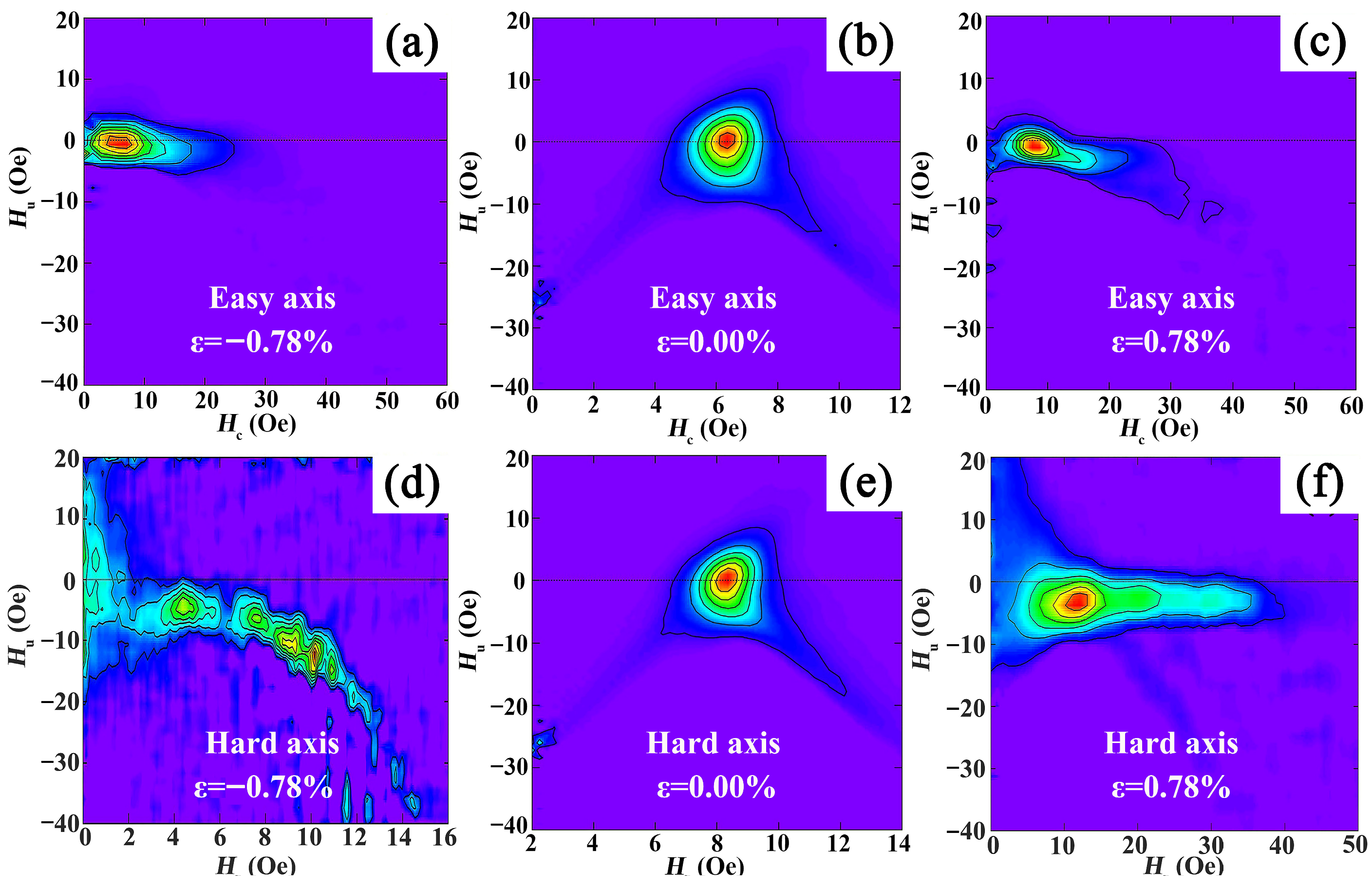
3.3. Magnetic Domain Analysis

MOKE measurements of the TFNFT multilayer films are performed, and the images are shown in Figure 7. The dark and light colors represent the two different states of magnetization with the magnetic moment perpendicular to the film face downward and upward, respectively. The MOKE images in the sample when the compression strain is ε = −0.78% is shown in Figure 7(a1–f1). When the external magnetic field is applied, all magnetic moments appear upward (as shown in Figure 7(a1)). In Figure 7(b1), the external magnetic field gradually increases to −1.10 mT, and the domain wall is displaced. When the external magnetic field is increased to −1.59 mT, the magnetic moment is completely reversed in the first step, as shown in Figure 7(d1). The external magnetic field c reverses and increases to 1.21 mT, and the domain wall shifts, as shown in Figure 7(e1). When the external magnetic field increases to 1.51 mT, the magnetization state of the magnetic moment becomes completely perpendicular to the film surface (Figure 7(f1)). The whole process of flipping the magnetic domains in the sample is achieved by changing the magnitude of the external magnetic field perpendicular to the film surface.
The MOKE images of the magnetic domain change in the sample when there is no external strain, as shown in Figure 7(a2–f2). As shown in Figure 7(a2–d2), when the external magnetic field is −1.42 mT, the magnetization state of the magnetic moments in the film surface is perpendicular to the film surface. Gradually increasing the external magnetic field to −2.58 mT, the domain wall nucleation appears. As the external magnetic field increases to −4.01 mT, the growth, expansion, and overturning process occurs sequentially. The MOKE images of the magnetic domain change in the sample when the tensile strain is ε = 0.78%, as shown in Figure 7(a3–f3). When the sample is subjected to tensile and compressive strain, the magnetic moment is reversed consistently over a large range. It shows a dendritic expansion process, which finally achieves the reversal process of the magnetic domain in the sample when the sample is not subject to external strain. It can be seen that the strain has a strong influence on the magnetic domains of the film. As the strain increases, the influence of the degenerate magnetic field in the sample decreases and the in-plane anisotropy increases.

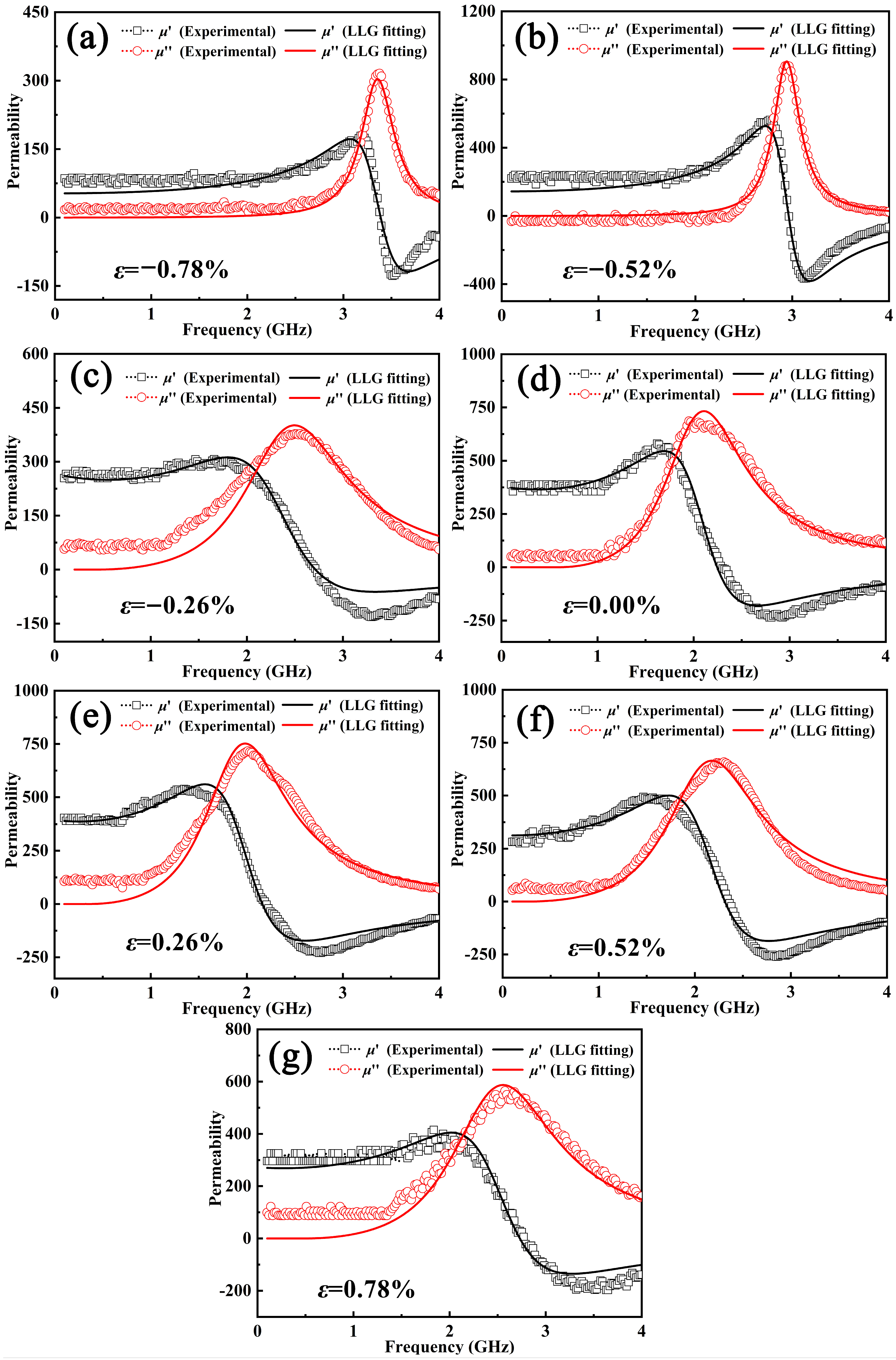
3.4. High-Frequency Properties

Based on the Kittle equation [26], the fr of magnetic films depends on the in-plane uniaxial anisotropy field. According to Figure 4, the in-plane anisotropy field increases with the strain. The complex permeability spectra of TFNFT multilayer films grown with various pre-strains are shown in Figure 8, to evaluate the impact of strain on the dynamic characteristics of TFNFT multilayer films. The LLG (Landau–Liftshitz–Gilbert) equation is used to fit the experimental results [32]. It is clear from Figure 8 that the experimental data is consistent with the fitted curve. With the compressive strain increasing from ε = 0% to ε = −0.78%, μi decreases from 385 to 80, while fr increases from 1.9 to 3.4 GHz, as shown in Figure 8a–d. The result reflects the positive correlation between the in-plane uniaxial magnetic anisotropy and the fr of the TFNFT multilayer films. The initial susceptibility decreases with increasing strain. The opposite features can be explained by Snoek–Archer’s limit and are associated with an exchange behavior between fr and permeability [32,33]. With the tensile strain increasing from ε = 0% to ε = 0.78%, μi decreases from 385 to 300, while fr increases from 1.9 to 2.5 GHz, as shown in Figure 8d–g. For all samples, as the frequency is increased, there is the displacement and split of the peaks. At the higher frequencies, the Villary effect is mainly due to the resonance frequency effect [34]. It can be seen that the compressive strain can effectively modulate the fr compared to the tensile strain.

4. Conclusions

In summary, we employed a pre-stretched and compressed surface structure on PET to fabricate flexible TFNFT multilayer films. We reported the effects of the strain on the microscopic morphology, magnetic domain morphology, and magnetic properties of TFNFT multilayer films. They showed uniaxial magnetic anisotropy and displayed good high-frequency performance, with μi varying from 80 to 385 and fr varying from 1.9 to 3.4 GHz by varying the pre-strain. When pre-strained uniaxial tensile and compressive strains were applied to the TFNFT film, the surface morphology of the sample exhibited different states. Moreover, μi c varied continuously around a few hundred units, and fr varied in the range of 1.5 GHz. These results demonstrate a simple and convenient method for continuously tuning the high-frequency characteristics of flexible magnetic films by applying uniaxial strain. Flexible magnetic films have a wide range of tunable resonance frequencies, which paves a new way to develop flexible high-frequency devices with adjustable mechanical strain. Moreover, it plays a vital role in magnetic-integrated device applications.

Author Contributions

Conceptualization, Z.H., X.J. and K.S.; Methodology, Z.H., Z.M., Y.D., J.Y., X.J. and K.S.; Writing-original draft, Z.H.; Writing—review & editing, Z.H., Q.L., Z.L. (Ziyu Li) and K.S.; Investigation, C.W. (Chuanjian Wu); Software, C.W. (Chaoming Wang); Visualization, Z.Y. and Z.L. (Zhongwen Lan); Project administration: Z.Y.; Validation, Z.L. (Zhongwen Lan); Funding acquisition, K.S.; Supervision, K.S. All authors have read and agreed to the published version of the manuscript.

Funding

This present work was financially supported by the National Natural Science Foundation of China under Grant Nos. 52172267 and 51772046, and the Innovation Group Project of Sichuan Province (2022JDTD0018).

Institutional Review Board Statement

Not applicable.

Informed Consent Statement

Not applicable.

Data Availability Statement

Data underlying the results presented in this paper are not publicly available at this time but may be obtained from the authors upon reasonable request.

Conflicts of Interest

The authors declare no conflict of interest.

References

  1. Su, Z.; Bennett, S.; Hu, B.; Chen, Y.; Harris, V.G. Magnetic and microwave properties of U-type hexaferrite films with high remanence and low ferromagnetic resonance linewidth. J. Appl. Phys. 2014, 115, 17A504. [Google Scholar] [CrossRef]
  2. Osaka, T.; Takai, M.; Hayashi, K.; Ohashi, K.; Saito, M.; Yamada, K. A Soft Magnetic CoNiFe film with high saturation magnetic flux density and low coercivity. Nature 1998, 392, 796–798. [Google Scholar] [CrossRef]
  3. Chen, X.; Ma, Y.G.; Ong, C.K. Magnetic Anisotropy and resonance frequency of patterned soft magnetic strips. J. Appl. Phys. 2008, 104, 013921. [Google Scholar] [CrossRef]
  4. Belyaev, B.A.; Lemberg, K.V.; Serzhantov, A.M.; Leksikov, A.A.; Bal’va, Y.F.; Leksikov, A.A. Magnetically tunable resonant phase shifters for UHF band. IEEE Trans. Magn. 2015, 51, 1–5. [Google Scholar] [CrossRef]
  5. Sharma, V.; Khivintsev, Y.; Harward, I.; Kuanr, B.K.; Celinski, Z. Fabrication and characterization of microwave phase shifter in microstrip geometry with Fe film as the frequency tuning element. J. Magn. Magn. Mater. 2019, 489, 165412. [Google Scholar] [CrossRef]
  6. Li, Q.; Chen, Y.; Yu, C.; Young, L.; Spector, J.; Harris, V.G. Emerging Magnetodielectric Materials for 5G Communications: 18H Hexaferrites. Acta Mater. 2022, 231, 117854. [Google Scholar] [CrossRef]
  7. Kuanr, B.K.; Veerakumar, V.; Camley, R.E.; Celinski, Z. Permalloy (NiFe) nanometer square-antidot arrays: Dynamic modes and use as a monolithic microwave band-pass filter. J. Magn. Magn. Mater. 2019, 484, 272–278. [Google Scholar] [CrossRef]
  8. Lu, Q.; Yu, B.; Hu, Z.; He, Y.; Hu, T.; Zhao, Y.; Wang, Z.; Zhou, Z.; Cui, W.; Liu, M. Surface roughness evolution induced low secondary electron yield in carbon coated Ag/Al substrates for space microwave devices. Appl. Surf. Sci. 2020, 501, 144236. [Google Scholar] [CrossRef]
  9. Paiva, D.V.M.; Silva, M.A.S.; Sombra, A.S.B.; Fechine, P.B.A. Properties of the Sr3MoO6 electroceramic for RF/microwave devices. J. Alloys Compd. 2018, 748, 766–773. [Google Scholar] [CrossRef]
  10. Talapatra, A.; Arout Chelvane, J.; Satpati, B.; Kumar, S.; Mohanty, J. Tunable magnetic domains and depth resolved microstructure in Gd-Fe thin films. J. Alloys Compd. 2019, 774, 1059–1068. [Google Scholar] [CrossRef]
  11. Streubel, R.; Lee, J.; Makarov, D.; Im, M.; Karnaushenko, D.; Han, L.; Schäfer, R.; Fischer, P.; Kim, S.; Schmidt, O.G. Magnetic microstructure of rolled-up single-layer ferromagnetic nanomembranes. Adv. Mater. 2014, 26, 316–323. [Google Scholar] [CrossRef]
  12. Zheng, C.; Kirmse, H.; Long, J.; Laughlin, D.E.; McHenry, M.E.; Neumann, W. Investigation of (Fe, Co)NbB-based nanocrystalline soft magnetic alloys by lorentz microscopy and off-axis electron holography. Microsc. Microanal. 2015, 21, 498–509. [Google Scholar] [CrossRef]
  13. Shen, C.Y.; Yeh, P.Y.; Yuan, F.T.; Chang, H.W.; Lee, M.Y.; Lin, D.Y.; Wang, C.R. Improved perpendicular magnetic properties of pulsed-dc-sputtered FePt thin films. Surf. Coat. Technol. 2018, 350, 795–800. [Google Scholar] [CrossRef]
  14. Jin, S.; Zhu, W.; Tiefel, T.H. Fe-Cr-N soft magnetic thin films. J. Appl. Phys. 1997, 81, 4042–4044. [Google Scholar] [CrossRef]
  15. Han, X.M.; Ma, J.H.; Wang, Z.; Yao, Y.L.; Zuo, Y.L.; Xi, L.; Xue, D.S. Tunable in-plane uniaxial anisotropy and the magnetization reversal mechanism of patterned high-frequency soft magnetic FeTa strips. J. Phys. D Appl. Phys. 2013, 46, 485004. [Google Scholar] [CrossRef]
  16. Phuoc, N.N.; Ong, C.K. Observation of magnetic anisotropy increment with temperature in composition-graded FeCoZr thin films. Appl. Phys. Lett. 2013, 102, 212406. [Google Scholar] [CrossRef]
  17. Lou, Z.; Wang, L.; Shen, G. Recent advances in smart wearable sensing systems. Adv. Mater. Technol. 2018, 3, 1800444. [Google Scholar] [CrossRef]
  18. Liu, C.; Cai, J.; Li, X.; Zhang, W.; Zhang, D. Flexible and tunable electromagnetic meta-atom based on silver nanowire networks. Mater. Des. 2019, 181, 107982. [Google Scholar] [CrossRef]
  19. Yang, S.; Liu, P.; Yang, M.; Wang, Q.; Song, J.; Dong, L. From Flexible and Stretchable Meta-Atom to Metamaterial: A Wearable Microwave Meta-Skin with Tunable Frequency Selective and Cloaking Effects. Sci Rep. 2016, 6, 21921. [Google Scholar] [CrossRef] [PubMed]
  20. Gutruf, P.; Zou, C.; Withayachumnankul, W.; Bhaskaran, M.; Sriram, S.; Fumeaux, C. Mechanically Tunable Dielectric Resonator Metasurfaces at Visible Frequencies. ACS. Nano 2016, 10, 133–141. [Google Scholar] [CrossRef] [Green Version]
  21. Liu, W.; Shen, Y.; Xiao, G.; She, X.; Wang, J.; Jin, C. Mechanically tunable sub-10 nm metal gap by stretching PDMS substrate. Nanotechnology 2017, 28, 075301. [Google Scholar] [CrossRef]
  22. Li, J.; Shah, C.M.; Withayachumnankul, W.; Ung, B.S.-Y.; Mitchell, A.; Sriram, S.; Bhaskaran, M.; Chang, S.; Abbott, D. Mechanically tunable terahertz metamaterials. Appl. Phys. Lett. 2013, 102, 121101. [Google Scholar] [CrossRef]
  23. Tang, Z.; Wang, B.; Yang, H.; Xu, X.; Liu, Y.; Sun, D.; Xia, L.; Zhan, Q.; Chen, B.; Tang, M.; et al. Magneto-mechanical coupling effect in amorphous Co40Fe40B20 films grown on flexible substrates. Appl. Phys. Lett. 2014, 105, 103504. [Google Scholar] [CrossRef]
  24. Liu, J.; Chen, J.; Zhang, Y.; Fu, S.; Chai, G.; Cao, C.; Zhu, X.; Guo, Y.; Cheng, W.; Jiang, D.; et al. Stretching-tunable high-frequency magnetic properties of wrinkled CoFeB films grown on PDMS. ACS. Appl. Mater. Interfaces 2021, 13, 29975–29983. [Google Scholar] [CrossRef]
  25. Dai, G.; Zhan, Q.; Liu, Y.; Yang, H.; Zhang, X.; Chen, B.; Li, R.-W. Mechanically tunable magnetic properties of Fe81Ga19 films grown on flexible substrates. Appl. Phys. Lett. 2012, 100, 122407. [Google Scholar] [CrossRef]
  26. Kittel, C. Interpretation of anomalous larmor frequencies in ferromagnetic resonance experiment. Phys. Rev. 1947, 71, 270–271. [Google Scholar] [CrossRef]
  27. Li, Y.F.; Li, E.; Zhang, Y.P.; Zhao, C.; Yang, T. Ultra-wideband variable temperature measurement system for complex permeability of magnetic thin film Fe66Co17B16Si1. IEEE Trans. Magn. 2018, 54, 1–7. [Google Scholar] [CrossRef]
  28. Kurlyandskaya, G.V.; Fernández, E.; Svalov, A.; Burgoa Beitia, A.; García-Arribas, A.; Larrañaga, A. Flexible Thin Film Magnetoimpedance Sensors. J. Magn. Magn. Mater. 2016, 415, 91–96. [Google Scholar] [CrossRef]
  29. Neudert, A.; McCord, J.; Schäfer, R.; Schultz, L. Dynamic anisotropy in amorphous CoZrTa films. J. Appl. Phys. 2004, 95, 6595–6597. [Google Scholar] [CrossRef]
  30. Wu, C.; Wang, W.; Li, Q.; Wei, M.; Luo, Q.; Fan, Y.; Jiang, X.; Lan, Z.; Jiao, Z.; Tian, Y.; et al. Barium Hexaferrites with Narrow Ferrimagnetic Resonance Linewidth Tailored by Site-controlled Cu Doping. J. Am. Ceram. Soc. 2022, 105, 7492–7501. [Google Scholar] [CrossRef]
  31. Xu, J.; Zhang, J.; Wang, J.; Hong, B.; Peng, X.; Wang, X.; Ge, H.; Hu, J. Effects of gradient diameter on magnetic properties of FeNi alloys nanowires arrays. J. Magn. Magn. Mater. 2020, 499, 166207. [Google Scholar] [CrossRef]
  32. Phuoc, N.N.; Xu, F.; Ong, C.K. Tuning magnetization dynamic properties of Fe–SiO2 multilayers by oblique deposition. J. Appl. Phys. 2009, 105, 113926. [Google Scholar] [CrossRef]
  33. Phuoc, N.N.; Xu, F.; Ong, C.K. Ultrawideband microwave noise filter: Hybrid antiferromagnet/ferromagnet exchange-coupled multilayers. Appl. Phys. Lett. 2009, 94, 092505. [Google Scholar] [CrossRef]
  34. Agra, K.; Mori, T.J.A.; Dorneles, L.S.; Escobar, V.M.; Silva, U.C.; Chesman, C.; Bohn, F.; Corrêa, M.A. Dynamic Magnetic Behavior in Non-Magnetostrictive Multilayered Films Grown on Glass and Flexible Substrates. J. Magn. Magn. Mater. 2014, 355, 136–141. [Google Scholar] [CrossRef]
Figure 1. Schematic diagram of electron beam evaporation of flexible TFNFT film: (a) concave mold, (b) convex mold.
Coatings 13 00363 g001
Figure 2. AFM images of the TFNFT multilayer films at various external strains: (a) ε = −0.78%, (b) ε = −0.52%, (c) ε = −0.26%, (d) ε = 0.00%, (e) ε = 0.26%, (f) ε = 0.52%, (g) ε = 0.78%.
Coatings 13 00363 g002
Figure 3. External strain dependence of surface roughness (Ra) and average grain size (D) in TFNFT multilayer films.
Coatings 13 00363 g003
Figure 4. Magnetic hysteresis loops of TFNFT multilayer films under various external strains: (a) tensile strain along the easy axis (EA), (b) tensile strain along the hard axis (HA), (c) compressive strain along the EA, (d) compressive strain along the HA.
Coatings 13 00363 g004
Figure 5. Static magnetic properties of TFNFT multilayer films under various external strains: (a) remanence ratio Mr/Ms in the EA and HA, respectively; (b) the coercivity (Hc).
Coatings 13 00363 g005
Figure 6. FORC diagrams of TFNFT multilayer films at various external strains: (a) ε = −0.78%, (b) no strain, (c) ε = 0.78% (along the EA); (d) ε = −0.78%, (e) no strain, (f) ε = 0.78% (along the HA).
Coatings 13 00363 g006
Figure 7. MOKE images of Ti/Fe/Ni81Fe19/Fe/Ti multilayer films. ((a1)–(f1)) indicate variations in the magnetic domain under an external strain of ε = −0.78%: (a1) −0.94 mT, (b1) −1.10 mT, (c1) −1.20 mT, (d1) −1.59 mT, (e1) 1.21 mT, and (f1) 1.51 mT; ((a2)–(f2)) indicate variations in the magnetic domain under no external strain: (a2) −1.42 mT, (b2) −2.58 mT, (c2) −2.72 mT, (d2) −4.01 mT, (e2) 2.66 mT, and (f2) 4.03 mT; ((a3)–(f3)) indicate variations in the magnetic domain under an external strain of ε = 0.78%: (a3) −0.68 mT, (b3) −0.88 mT, (c3) −1.57 mT, (d3) −0.82 mT, (e3) 0.93 mT, and (f3) 1.76 mT.
Coatings 13 00363 g007
Figure 8. Permeability spectra of TFNFT films at various external strains: (a) ε = −0.78%, (b) ε = −0.52%, (c) ε = −0.26%, (d) no strain, (e) ε = 0.26%, (f) ε = 0.52%, (g) ε = 0.78%.
Coatings 13 00363 g008
Disclaimer/Publisher’s Note: The statements, opinions and data contained in all publications are solely those of the individual author(s) and contributor(s) and not of MDPI and/or the editor(s). MDPI and/or the editor(s) disclaim responsibility for any injury to people or property resulting from any ideas, methods, instructions or products referred to in the content.

