Article

Application of Biocompatible Noble Metal Film Materials to Medical Implants: TiNi Surface Modification

by
Evgeniia S. Vikulova
1,
Ksenya I. Karakovskaya
1,
Ilya V. Korolkov
1,*,
Tatyana P. Koretskaya
1,
Elena V. Chepeleva
2,
Nikolay B. Kuz’min
3,
Anastasiya D. Fedorenko
1,
Denis P. Pischur
1,
Tatiana Ya. Guselnikova
1,
Eugene A. Maksimovskii
1,
Ekaterina S. Marchenko
4,
Aleksander A. Zheravin
2,* and
Natalya B. Morozova
1,*
1
Nikolaev Institute of Inorganic Chemistry, Siberian Branch, Russian Academy of Sciences, Ac. Lavrentiev Ave. 3, 630090 Novosibirsk, Russia
2
Meshalkin National Medical Research Center, Ministry of Public Health of the Russian Federation, Rechkunovskaya Str. 15, 630055 Novosibirsk, Russia
3
Rzhanov Institute of Semiconductor Physics, Siberian Branch, Russian Academy of Sciences, Ac. Lavrentiev Ave. 13, 630090 Novosibirsk, Russia
4
Kuznetsov Siberian Physical-Technical Institute, Tomsk State University, Novo-Sobornaya Sq. 1, 634050 Tomsk, Russia
*
Authors to whom correspondence should be addressed.
Coatings 2023, 13(2), 222; https://doi.org/10.3390/coatings13020222
Submission received: 15 December 2022 / Revised: 13 January 2023 / Accepted: 15 January 2023 / Published: 18 January 2023

Abstract

:
Recently, film materials based on the combination of noble metals have showed promising results for surface modification of medical implants, allowing both to improve biocompatibility and to acquire the increased antibacterial effect. An important challenge here is to combine the developed coating morphology, which is favorable for biological response, with a high protective function, which, on the contrary, requires a compact coating microstructure. In this work, we aimed to solve this problem with respect to the TiNi implant material. We have tested two types of compact thin sublayers: Iridium (Ir’), formed by metal-organic chemical vapor deposition (MOCVD), and gold (Au), formed by physical vapor deposition (PVD). Subsequently these sublayers were coated with a developed-columnar-iridium (Ir) by MOCVD. Features of the microstructure, chemical and phase composition of all these film materials were studied using powder X-ray diffraction (XRD), scanning electron microscopy (SEM) and X-ray photoelectron spectroscopy (XPS). The changes in the characteristics of TiNi martensitic transformation due to MOCVD experiments were also studied by differential scanning calorimetry (DSC). The biocompatibility of Ir’/TiNi, Au/TiNi, Ir/Ir’/TiNi, Ir/Au/TiNi samples was assessed by cytoxicity testing (Man-1 cells) and measuring of nickel content in the biological extracts. The application of both sublayers effectively reduces the release of nickel, which was previously shown for Ir/TiNi samples. This prevents the toxic effect. Note that the Ir’ sublayer better protects against nickel release, while the Au sublayer promotes cell proliferation.

Graphical Abstract

1. Introduction

A number of advantages over stainless steel and cobalt alloys, including better biocompatibility, osseointegration and corrosion resistance, lower weight and Young’s modulus, are driving the growing use of titanium and its alloys (e.g., Ti-6Al-4V) for the fabrication of medical hard tissue implants [1,2,3,4]. Despite the complicated processing [5], a special place here belongs to titanium and nickel alloys, in particular those close to the equiatomic composition, TiNi. These alloys are the most compatible with bone tissue in terms of biomechanical characteristics, and possess unique properties including shape memory effect due to reversible austenite–martensite phase transformation [1,6,7]. Notably, the characteristics of this transformation, such as temperature, can be tuned by changing the composition of the alloy or heat treatments [8,9,10].
The main complications after implant placement are due to infection and inflammation [11]. Therefore, it is necessary to modify the implant surface: Imparting an antibacterial effect will solve the first problem, while enchasing biocompatibility will prevent the second one [12,13,14,15,16,17,18]. Improvement in corrosion resistance is also desirable in order to prevent the leaching of metal cations that cause allergic and toxic reactions from the implant surface [4,19,20,21]. All this is especially important for oncological patients, since the percentage of sequela here is on average an order of magnitude higher due to suppressed immunity [11].
An effective approach to modify the surface properties of implants is the application of multifunctional coatings. For these purposes, the possibility of using composites based on ceramics [22,23,24], polymers [25,26], oxides [27,28], and other systems [29] is now being intensively studied. Promising results have recently been shown for film materials made from combinations of noble metals (Pt, Pd, Ir, Au, and Ag) [30,31], which are known to have an excellent biocompatibility and high corrosion resistance (Pt, Ir, Au). The main feature of such compositions is the enhanced antibacterial effect due to electrochemical effects and synergism. This effect can be tuned by varying the combination of metals, the amount of the bioactive component (usually Au or Ag) and the type of material: Bimetallic [32,33] or layered coatings [34], bimetallic nanoparticles (alloys/core-shell) [31,35,36,37,38], or a mixture of individual nanoparticles [39], heterostructures formed by discrete coatings [40], nanoparticles [40,41] or microarrays [42,43,44,45] of bioactive metal deposited onto a continuous layer of the more inert one.
Long-term model in vivo studies (up to three months) for Au/M and Ag/M (M = Pt, Ir, PtIr) heterostructures on a Ti-6Al-4V showed an acceleration of engraftment compared to uncoated alloy implants [40]. The best in vivo biocompatibility was observed for the heterostructures contained a continuous (bottom) layer with the most developed morphology, namely iridium with a columnar-dendritic microstructure obtained Metal-Organic Chemical Vapor Deposition (MOCVD). This is consistent with the favorable growth of fibroblasts onto high-roughness-surfaces [46,47]. Moreover, developed morphology is also preferable for promoting osseointegration [48]. Note that this iridium layer also improved the corrosion resistance of the Ti-alloy [40].
However, when such coating was applied to a TiNi carrier, a strong cytotoxic effect appeared due to increased nickel release [49]. It can be assumed that the application of a compact noble metal sublayer would solve this problem and impart a pronounced protective function to the materials being developed. In the current work, the aim was to test this hypothesis by evaluating the cytotoxicity and nickel release for TiNi coated with (i) a compact film or (ii) a layered structure formed by this compact film as a bottom and above discussed MOCVD-iridium with a developed morphology as a top. To prepare the protective (compact) layer, we involved both the traditional method of physical vapor deposition (using Au as an example) and an alternative MOCVD approach (using Ir as an example). Since the latter is attractive in terms of the formation of all parts of the heterostructures in one setup, special attention was focused on these objects. Compact iridium protective sublayers and the proposed layer-by-layer noble metal film materials on TiNi were obtained for the first time. A schematic illustration of the sample preparation is shown in Figure 1.

2. Materials and Methods

2.1. Substrates

TiNi alloy (Ti = 49.72 ± 0.18 at. %, Ni = 50.28 ± 0.18 at. %) was manufactured by remelting of titanium sponge and nickel in an induction furnace [50]. The resulting ingots were rolled into strips and then were cut to produce the 2 mm-thick plate substrates, namely 2 × 2 mm2 for DSC studies and 10 × 10 mm2 for other purposes. Additionally, 10 × 10 mm2 plates of monocrystalline Si(100) (Alga-SW, Novosibirsk, Russia) were used in the experiments of noble metal films deposition as model substrates.

2.2. MOCVD Precursors

Volatile iridium precursors for MOCVD experiments, Ir(CO)2(acac) and Ir(cod)(acac), cod = cyclooctadiene-1,5, acac = acetylacetonate, were prepared using a standard Schlenk equipment. Ir(cod)(acac) was synthesized via the reaction between [Ir(cod)Cl]2 (97%, Sigma-Aldrich Rus LLC, Moscow, Russia) and potassium salt of acetylacetone (Hacac, 99%, Dalchem, Nizhny Novgorod, Russia) obtained in situ [51]. Ir(CO)2(acac) was then prepared by passing of carbon monoxide flow through a hexane solution of Ir(cod)(acac) [52]. The precursors were purified by zone sublimation (5 × 10⁻² Torr, 140 and 100 °C for Ir(cod)(acac) and Ir(CO)2(acac), respectively) with 80% yield. The compounds were characterized by elemental analysis (vario MICRO cube, Elementar, Langenselbold, Hesse, Germany). For Ir(cod)(acac), IrC13O2H19, found C, 39.3; H, 4.9; calculated C, 39.1; H, 4.8 (wt.%). Saturated vapor pressure (100–150 °C): ln(p, atm) = 23.03 + 12,817/T (K); m.p. 155 °C [53]. For Ir(CO)2(acac), IrC7O4H7, found C, 24.0; H, 2.3; calculated C, 24.2; H, 2.0 (wt.%). Saturated vapor pressure (33–60 °C): ln(p, atm) = 22.40 + 11,293/T (K); m.p. 145 °C (dec.) [53].

2.3. Noble Metal Films Deposition

Gold thin films were prepared by the thermal evaporation of metallic Au (200 mg, 99.99%, Novosibirsk Refinery Plant OJSC, Novosibirsk, Russia) in vacuum (p = 5 × 10⁻⁷ Torr, Ievap. = 550 A) at substrate temperature of 300 °C using a standard UVN-71P-3 installation [54].
Iridium films were prepared in an original vertical cold-wall MOCVD reactor [49] at a reduced pressure (1.7–2.1 Torr) using argon as a carrier-gas.
Compact layers (Ir’) were deposited from Ir(CO)2(acac) using hydrogen (2 L/h) as a reagent-gas. The deposition and evaporation temperatures were varied in the ranges of 280–300 and 60–80 °C, respectively. The argon flow was 1 L/h and the experiment durations were 60–120 min. In some experiments, vacuum ultraviolet (VUV) stimulation was additionally used through Ar lamp (λ = 126 nm).
The coatings with columnar microstructure (Ir) were deposited from Ir(cod)(acac) using oxygen (2 L/h) as a reagent-gas [49]. The deposition and evaporator temperatures were 310 and 110 °C, respectively. The argon flow was 2 L/h and the experiment duration was 60 min.
Special batches of all-side-coated TiNi plates were prepared for DSC and cytotoxicity testing. Table 1 summarizes the samples onto TiNi substrates discussed in this work.

2.4. Characterization Methods

XRD analysis was applied to study the phase composition and structural features. For this, a Shimadzu XRD-7000 diffractometer (Shimadzu, Kyoto, Japan) equipped with OneSight linear detector was used. The XRD patterns were recorded with the step of 2θ = 0.0143° for 5 s with CuKα radiation (Ni filter, 2θ = 10–65°) or CoKα radiation (Fe filter, 2θ = 10–80°). The results were transferred to CuKα radiation. The data of PDF-2 database [55] were used for the qualitative phase analysis. The coherent scattering regions (CSR) were calculated according to the Scherrer equation taking into account the half-widths of an external polycrystalline silicon standard. Unit cell parameters (UCPs) of iridium were calculated in the PowderCell 2.4 program [56] using internal or external standards (Si substrate or polycrystalline silicon, respectively). The UCP of gold was calculated from the position of the (111) peak.
Scanning electron microscopy (SEM) was applied to study the microstructural features of the surface and cleavage of the obtained films. For this, a JEOL-ISM 6700 F microscope (JEOL, Kyoto, Japan) was used. For cross-section study of noble metal films on TiNi substrates, the samples were cut in half with a diamond cutting disc, then filled with SpeciFix-40 epoxy resin, ground with diamond grinding wheels and polished with Struers DP-Suspension P diamond suspensions on a Struers RotoPol-35 grinder and polisher. The used equipment and materials were manufactured by Struers (Ballerup, Denmark).
Energy dispersive analysis (EDX) was applied to primary estimate the elemental composition. For this, an analyzer EX-2300BU (JEOL, Tokyo, Japan) connected with a JEOL-ISM 6700 F microscope (JEOL, Tokyo, Japan) was used. EDX elemental mapping showed a uniform distribution of coating components (Figure S1).
XPS was applied to obtain the quantitative data on the chemical composition. For this, a FlexPS spectrometer (SPECS, Berlin, Germany) equipped with PHOIBOS-150 analyzer (1D DLD detector, SPECS, Berlin, Germany) and FOCUS-500 monochromator (Al Kα radiation, hv = 1486.71 eV, 200 W, SPECS, Berlin, Germany) was used. The binding energy (Eb) scale was calibrated based on the position of a Fermi edge (0.0 eV) for metallic samples [57]. The samples were etched to remove the surface contamination with 1 keV Ar+ ions for 10 min for Au/NiTi; 1 keV Ar+ ions for 30 min for Ir’/TiNi. The spectra were processed using the product of a Gaussian and Lorentzian function. For Ir 4f peaks fitting, the parameters proposed by Freakley et al. were used [58]. The background was taken into account using the Shirley method. Depth profiles was carried out using Ar+ sputtering etching with following parameters: for Ir’/TiNi = 1 keV ion energy during all etching; for Au/TiNi = 1 keV ion energy for 10 min and 30 min, respectively, and then 3 keV ion energy was used.

2.5. Differential Scanning Calorimetry

Differential scanning calorimeter (DSC, NETZSCH-Gerätebau GmbH, Selb, Germany) 204 F1 Phoenix was used to study phase transformations of bare and coated TiNi. DSC measurements of were carried out by heat flow measurement method at a constant heating/cooling rate of 9 ℃/min in 25 mL/min Ar flux in unsealed aluminum crucibles. Thermocycling of 3 samples weighting 150–170 mg of each film material was performed at least 2 times in temperature interval from −100 to +80 °C. Netzsch Proteus Analysis software was used to determine DSC peak areas and transition temperatures values. The transition temperatures were defined from the resulting heat flow as intersections of the peak onset and end with the corresponding baseline. The sensitivity of the sample carrier sensors calibration and temperature scale graduation were performed by melting and crystal-to-crystal transition measurements of standard samples: cyclohexane, adamantane, Hg, naphthalene, In, Sn (Certificate of verification No. C-C/02-02-2022/129404261).

2.6. Cytotoxicity Testing

The cytotoxicity tests were carried out by indirect contact. The extraction solutions (biological extracts) were prepared as a result of the keeping of TiNi, Ir’/TiNi, Au/TiNi, Ir/Ir’/TiNi and Ir/Au/TiNi samples in Dulbecco’s modified Eagle’s medium (DMEM, Thermo Fisher Scientific, Waltham, MA, USA) in a humidified atmosphere with 5% CO2 at 37 °C for 72 h [59]. The sample surface area to extraction medium ratio was 1.25 mL/cm2.
The cytotoxicity was examined towards to Man-1 cells obtained from the cell culture collection of Laboratory of Developmental epigenetics of the Federal Research Center Institute of Cytology and Genetics SB RAS [60]. The cells were cultured in DMEM medium, supplemented with 10% fetal bovine serum (Thermo Fisher Scientific, Waltham, MA, USA), 100 U/mL penicillin (Gibco, Waltham, MA, USA), 100 U/mL streptomycin (Gibco, Waltham, MA, USA) and 2 mmol/L L-glutamine (Invitrogen, Carlsbad, CA, USA) at 37 °C in a humidified atmosphere with 5% CO2. The control groups involved the use of DMEM medium as negative controls. Cells were incubated in 96-well flat-bottomed cell culture plates at 1 × 10⁴ cells per 200 μL in each well and incubated for 24 h to allow attachment. The medium was then replaced with 200 μL of extracts. After incubating the cells in the extracts under standard conditions (37 °C, humidified atmosphere with 5% CO2) for 1, 3, and 5 days, cell morphologies were observed by optical microscopy (Nikon Ti-E microscope, Nikon, Tokyo, Japan). The cytotoxic effect was measured using the Cell Proliferation Kit XTT (Applichem, PanReac Applichem, Barcelona, Spain). The optical density of the well contents was measured at a wavelength of 450 nm and a reference wavelength of 655 nm using an iMark plate photometer (Bio-Rad Laboratories Inc., Hercules, CA, USA). DMEM medium was a reference solution. Cell viability was calculated as a ratio of the differences between the optical density of the samples and the corresponding reference solution (A): Cell viability = (Aexperimental group/Acontrol) × 100%.

2.7. Statistical Analysis

Statistical processing of the results was carried out using the STATISTICA 8.0 software (StatSoft Inc., Tulsa, OK, USA). Normality of data distribution was assessed using the Shapiro-Wilk test. Mann-Whitney U-test was used to identify differences between groups. Differences between groups were considered significant at p < 0.05. The results are presented as median and interquartile range.

2.8. Biological Extracts Studies

Inductively coupled plasma atomic emission spectroscopy (ICP-AES) was applied to determine the metal contents in the biological extracts obtained for the cytotoxicity study. For this, a High-Resolution Spectrometer iCAP 6500 (Thermo Fisher Scientific, Waltham, MA, USA) was used. A pneumatic spray system was used to inject the sample solution. The nebulizer was of the SeaSpray type (Glass Expansion, Melbourne, Australia), the peristaltic pump rate was 0.7 mL/min. Metal concentration was determined at instrumental conditions recommended by the manufacturer: cooling argon flow = 12 L/min, secondary = 0.5 L/min; registration time on the first slit = 15 s; on the second slit = 5 s, the power supplied to ICP inductor was 1150 W. The plasma was observed axially to register emission spectra to provide high analytical signals [61,62]. The solutions for quantitative measurements were prepared by adding purified sub-boiler distillation concentrated nitric acid (DuoPur system, Millistone, Italy) and heating at 85–90 °C for 30 min. Then, solutions were diluted with ultra-pure water >18 MOhm/cm obtained on a Direct-Q3 system (Millipore, Burlington, MA, USA). Calibration curves were obtained using a multi-element standard solution (Skat, Novosibirsk, Russia) contained 50 µg/mL of Ni and Ti. Metal concentrations were determined by analytical lines without spectral interferences: 231.604 and 221.641 nm for Ni; 336.121 and 337.280 nm for Ti.
A pH-meter Anion 4102 with a combined glass electrode ESK-10601/7 (Infraspack-Analit, Novosibirsk, Russia) was applied to measure the pH of extracts. The electrode was calibrated against standard buffer solutions (pH = 6.86, 9.18).

3. Results and Discussion

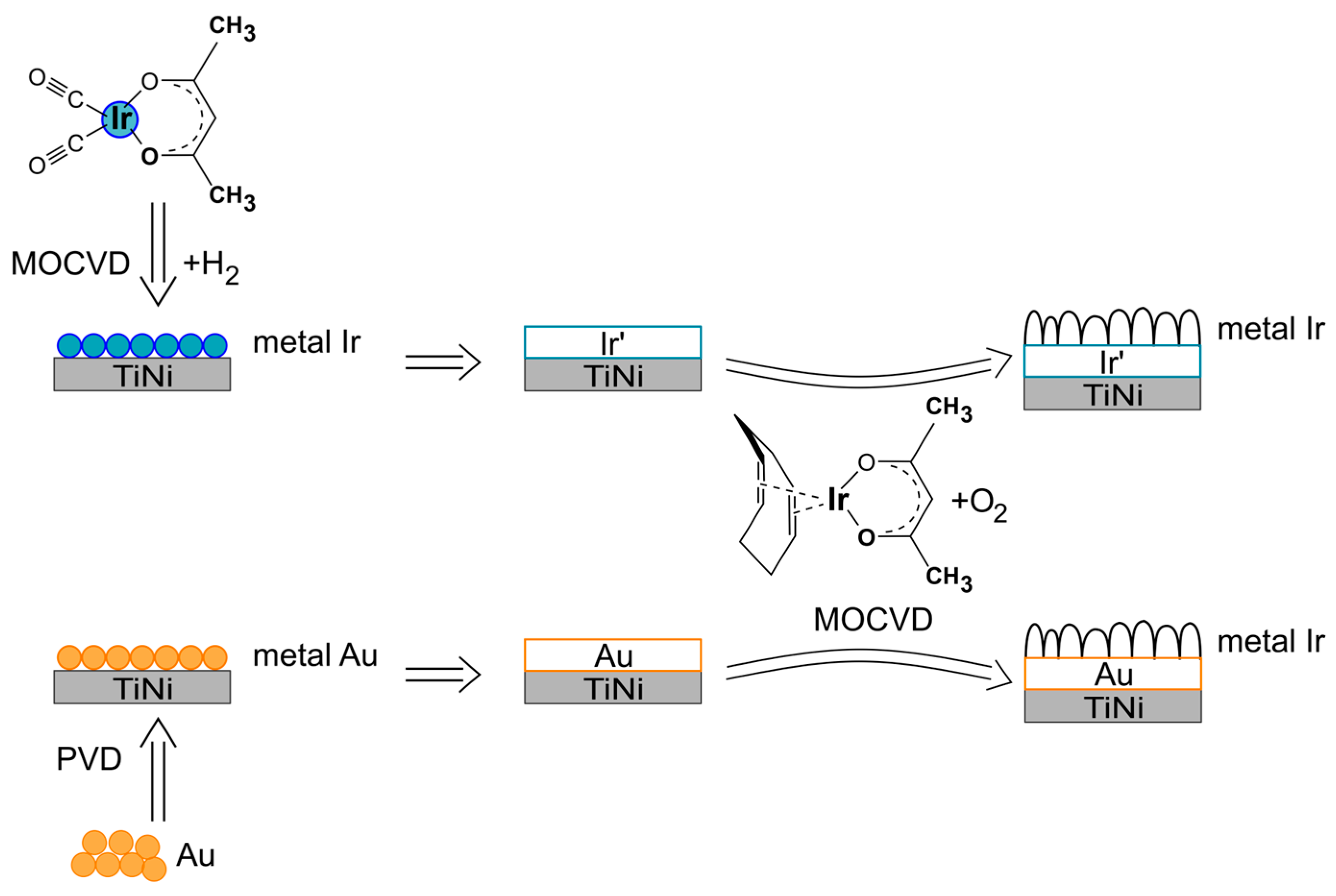
3.1. Composition and Microstructure of Compact Iridium Sublayers on Si(100) Substrates

The formation of an ideal protective layer characterized by a compact/dense microstructure is a specific challenge within the MOCVD approach. For this, the deposition process should be organized to afford a large density of relatively disperse and fine nuclei on the substrate surface [63]. The subsequent coalescence of such nuclei into a film without a significant increase in their size leads to the desired microstructure. Accordingly, such processes generally require low growth rates.
In the case of iridium MOCVD, the similar disperse nuclei were shown to be able to form during the deposition from iridium(III) acetylacetonate, Ir(acac)3, in a reducing atmosphere (gas-reagent = H2) at the bottom of the film growth temperature boundary [64]. However, in traditionally organized MOCVD processes, such a layer is too thin, and then the particles are condensed and/or combined into characteristic columnar-dendritic agglomerates [65]. In addition, it is important to note that the Ir(acac)3 has a relatively high vapor thermal stability in the presence of hydrogen [53]. Therefore, iridium films can be successfully deposited at temperatures above 400 °C [53,66]. At the same time, lower temperatures are favorable for preventing both the agglomeration of primary metallic particles and thermally induced strong changes of the substrate. In the case of TiNi, heat treatments above 450 °C increase the further nickel leaching into solutions, which is unacceptable for biological applications [67].
Thus, for obtaining the iridium compact films being able to perform the protective sublayer function, herein we select a special iridium precursor, Ir(CO)2(acac). In fact, this compound is characterized by the reduced vapor decomposition temperatures in the presence of hydrogen [53]. The presence of carbonyl (CO) groups potentially provides an additional route to promote decomposition through irradiation [68]. In this work, we have tested this possibility using vacuum ultraviolet (VUV) stimulation. Note that the features of the formation of iridium layers via MOCVD in the presence of hydrogen at relatively low temperatures (≤300 °C) have not been previously described.
To determine the optimal deposition conditions, a series of MOCVD experiments were carried out using silicon as a model substrate. The experimental parameters were selected to ensure low growth rates (no more than 1 nm/min). The temperatures of deposition and evaporator, exposure time, as well as VUV-stimulation were varied. The deposition conditions for the representative samples are shown in Table 2.
It should be noted that all the coated samples visually look like metallic mirrors. However, no reflections, except for the Si(100) substrate, appeared in the XRD patterns of all the obtained samples. This clearly indicates a very low crystallinity/amorphism of the films. The presence of iridium is clearly reflected in the EDX spectra. The SEM study allows us to determine the features of the surface and cross-section morphology of the coatings and to estimate their thickness. Further, the growth rates were calculated as the ratio of thicknesses to deposition times (Table 2).
All the films are formed by fine and relatively homogeneous particles (10–20 nm, Figure S2). Samples 1 and 2 illustrate the effect of VUV stimulation. Additional activation increases the growth rate (by about 20%–25%), but the particle size decreases (Figure 2a,b). Apparently, this indicates an acceleration of the precursor decomposition process, and consequently, a higher nucleation density. This reduces particle agglomeration and results in a more compact microstructure (Figure 2b). Therefore, we focus on obtaining samples using VUV activation below.
Decreasing the evaporator temperature (samples 2 and 3) lowers the concentration of the precursor in the reaction zone, and as expected, reduces the film growth rate (Table 2). At the same time, an increase in the deposition time makes it possible to obtain thicker films without a significant loss in the quality of the target microstructure (Figure 2c). However, the more pronounced signs of agglomeration (<30 nm) appear on the surface.
An increase in the deposition temperature (samples 3 and 4) also leads to a decrease in the film growth rate. The particles here are more homogeneously distributed over the surface (Figure 2d). Apparently, these changes are induced by the fact that the precursor begins to decompose in the gas phase, and thus, part of the substance does not reach the substrate.
Thus, to obtain a protective iridium sublayer on TiNi, we selected the conditions for the preparation of sample 3.

3.2. Deposition of Protective Noble Metal Sublayers onto TiNi Substrates

The compact iridium films (protective sublayers) were deposited onto TiNi substrates by MOCVD under the conditions defined above (Section 3.1, Table 2, Sample 3). This sample group will be referred to as “Ir’/TiNi”.
Only the reflections of the substrate are clearly observed in the diffraction patterns of Ir’/TiNi (Figure 3). However, a small shoulder in the region of 2θ = 40.7° can be attributed to metallic iridium ((111) reflection of fcc-Ir) of low crystallinity. The EDX data confirm the successful deposition of the iridium layer.
The quantitative composition of the resulting film has been determined using XPS. The depth profiles of the element concentrations are shown in Figure 4a. According to Ir 4f spectra, in addition to metallic iridium Ir0 with a binding energy of 60.9 eV, IrO2 with a binding energy of 61.5 eV is observed on the surface Ir’ layer (Figure 5a). However, the amount of the oxidized iridium is insignificant (8.9%). When etching deep into the film, only the components related to metallic iridium remain in the Ir 4f spectrum. When approaching the film-substrate interface, a line related to the oxide reappears in the spectrum; its area does not exceed 1%. According to the C1s spectrum, various carbon groups are observed on the sample surface: C-C, C-OH, C=O, and COOH with binding energies of 284.6 eV, 286.2 eV, 287.1 eV, and 288.8 eV, respectively (Figure 5b). Only C-C with a binding energy of 284.3 eV remains in the depth of the film. Contributions from C-OH groups appear at the film-substrate interface in the spectrum of C1s (285.8 eV). In the case of O1s spectra, when approaching the TiNi surface, an increase in the component related to metal oxides with a binding energy (530.7 eV) is observed (Figure 5c). This is primarily due to the spontaneous oxidation of titanium on the TiNi surface (native oxide film) [69]. In particular, only lines related to the metal (852.9 eV) are observed at Ni 2p spectra (Figure 5e). However, in the spectra of Ti 2p (Figure 5d), there are intense components related to the oxidized states of the metal with the total contribution of 85.1% (TiII–455.7 eV, TiIII–457.3 eV, TiIV–459.1 eV).
According to SEM, the shapes and sizes of the surface particles for Ir’/TiNi (Figure S3a) correspond to those observed on the model Si sample (Figure S2). On smooth areas, the particles are sufficiently segregated. However, the primary inhomogeneity of the TiNi surface leads to the formation of globular primary Ir’ agglomerates (~0.1–0.2 µm, Figure 6b). They are grouped into secondary agglomerates up to 1.5 μm in size (Figure 6b), apparently at the sites of the surface microdefects of the TiNi surface (Figure 6a). It should be underlined that there are practically no cracks and clearances in the Ir’ layer. This allows us to expect an effective protective function.
Since different PVD techniques are traditionally used to produce protective coatings for metallic materials [70,71,72], we have also adopted this approach here. In particular, the gold films were deposited onto TiNi substrates via thermal PVD using well-developed procedures [54]. We have adjusted the mass of the metal weight to provide a thickness comparable to the iridium sublayer (Ir’) described above (~90 nm, according to model samples on Si(100)). This sample group will be referred to as “Au/TiNi”.
The results of XRD analysis confirm the formation of the fcc-Au phase (2θ = 38.4° (111), 44.0° (200)). A characteristic strong (111) texture [54] is also observed (Figure 3). The average sizes of the crystallites oriented in (111) and (200) directions calculated from the CSR are 170–180 and 48–57 nm, respectively. The calculated unit cell parameter, a(Au), is 4.082(3) Å, which corresponds to pure gold (4.080 Å, PDF 010-75-6560).
The quantitative composition of the film has been studied using XPS. The depth profiles of the element concentrations are shown in Figure 4b. According to the Au 4f spectra, gold is in the metallic Au0 state with a binding energy of 84.0 eV over the entire depth of the film (Figure 7a). The C1s spectra (Figure 7b) show the presence of various carbon groups on the film surface: C-C, C-OH, C=O, and COOH with binding energies of 284.5 eV, 285.9 eV, 287.0 eV, and 288.3 eV, respectively, as for the Ir’/TiNi sample. No contributions of oxygen and carbon are observed in the depth of the film. When approaching the TiNi surface, the C1s and O1s spectra (Figure 7b,c) show lines corresponding to metal bonds (282.4 eV and 530.6 eV, respectively). Note that the gold here remains in the state Au0. At the same time, in the spectrum of Ti 2p related (Figure 7d) to the surface of TiNi, in addition to the metallic state Ti0 with a binding energy of 454.4 eV (providing the largest contribution of 51%), oxidized states of titanium are also observed (TiII–455.3 eV, TiIII–457.2 eV, TiIV–459.1 eV). It can be assumed that the native titanium oxide is partially transformed here into the corresponding carbide. This aspect needs further study. In the case of the Ni 2p spectra (Figure 7e), only the features related to metallic nickel Ni0 with a binding energy of 853.0 eV are observed. The surface of the substrate is enriched with nickel.
According to SEM, the film surface is formed by particles with sizes of about 50 nm (Figure S3b). In general, the relief of the Au layer repeats the initial relief of the alloy surface interspersed with primary near globular agglomerates (Figure 6c) similar to those described for the Ir’ layer (Figure 6b). Chaotic secondary agglomerates (Figure 8b) also form at the large surface microdefects of initial TiNi (Figure 8a). Here, the cracks appear in the Au layer, the substrate surface in them is filled with small gold particles 10–20 nm in size (Figure S4). Thus, the protective function, can apparently be performed quite effectively.

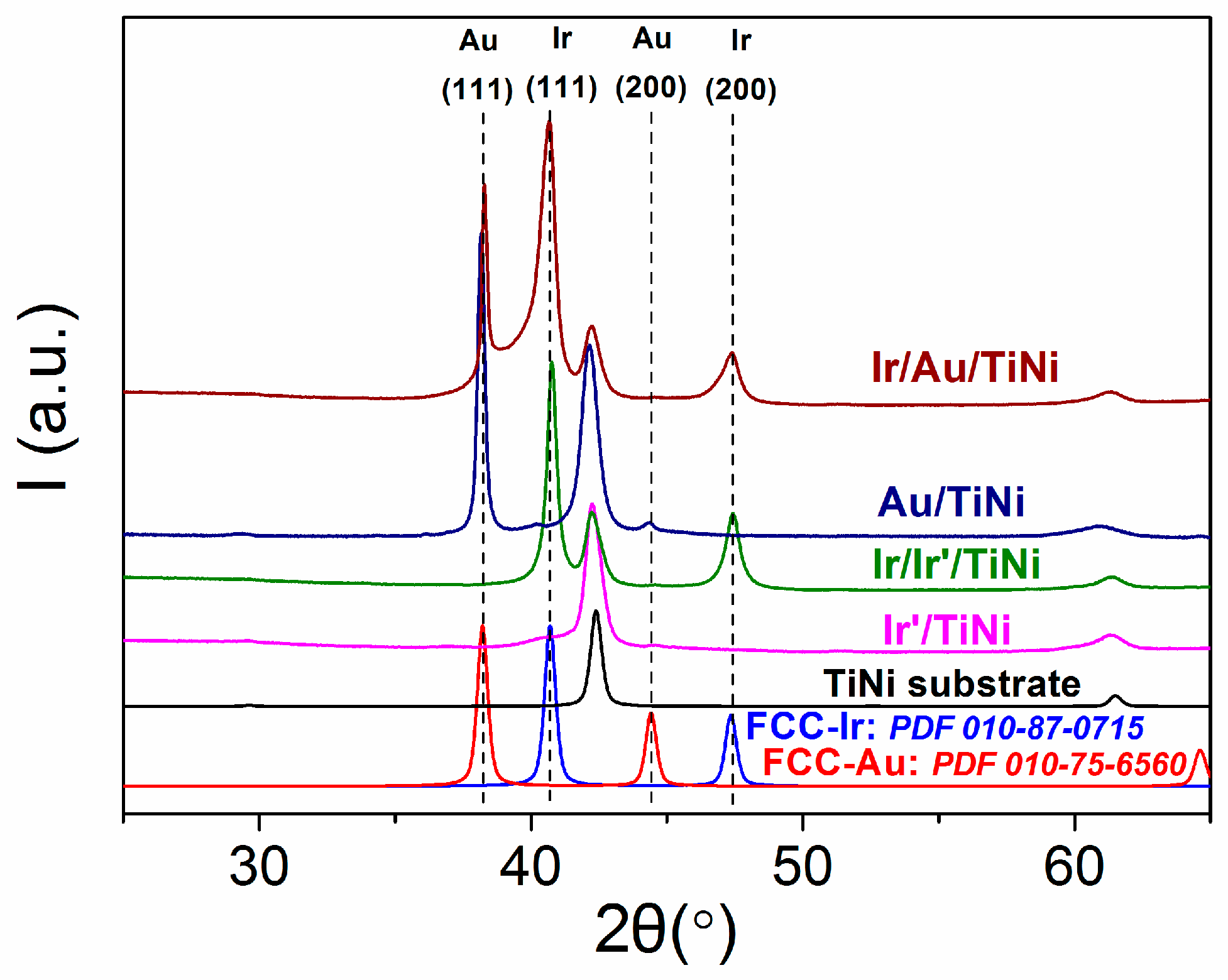
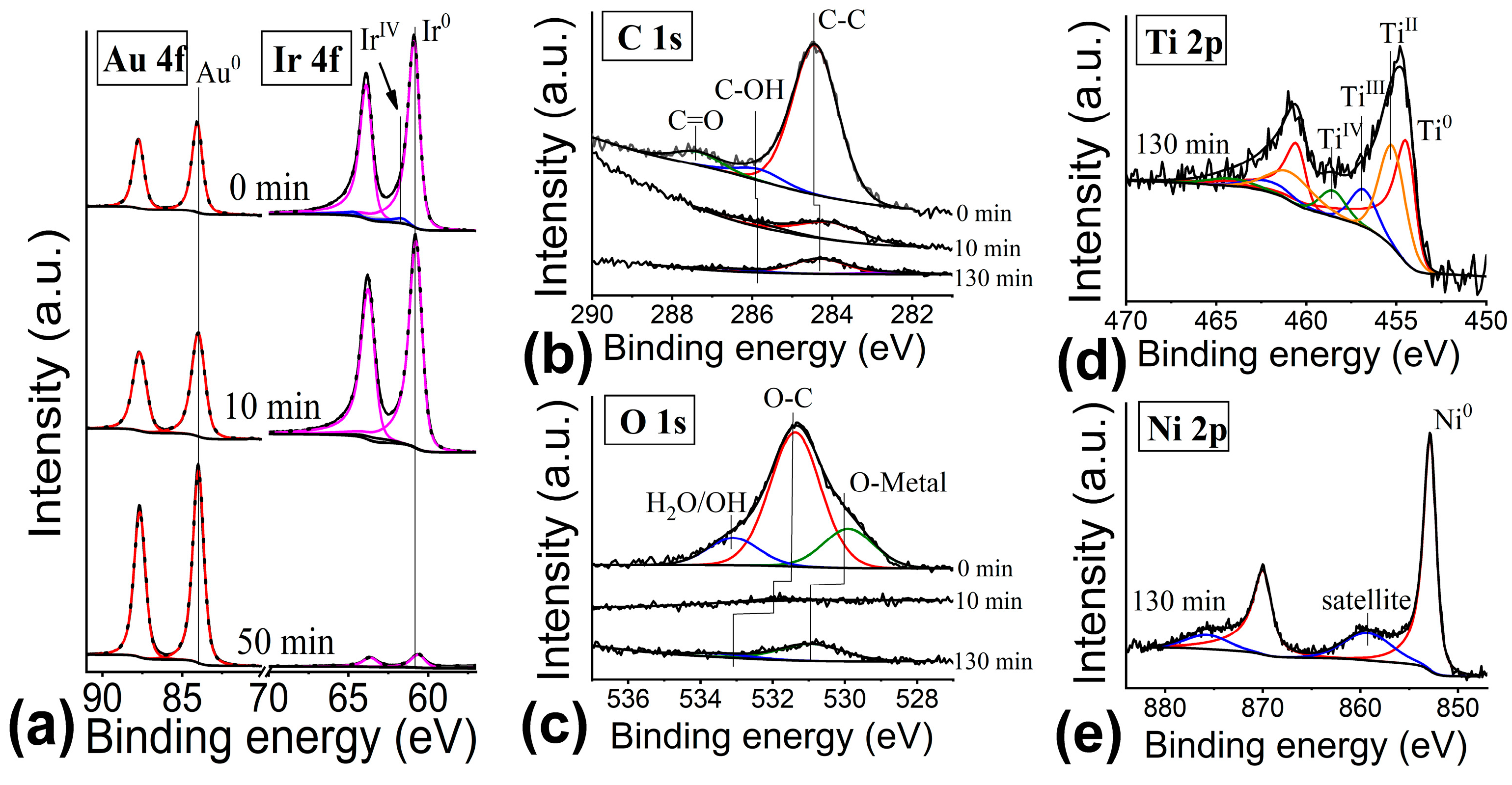
3.3. Deposition of Developed Ir onto TiNi Substrates Coated with Noble Metal Sublayers

The next step was the formation of an iridium film with a developed morphology on both tested sublayers. For this purpose, we have chosen the MOCVD-Ir-coatings with a columnar-dendritic microstructure, which, being previously deposited on TiNi without a sublayer (Ir/TiNi), actively stimulated the release of nickel ions [49]. Here we applied the published MOCVD procedures using Ir(cod)(acac) precursor in oxidation atmosphere to cover the Ir’/TiNi and Au/TiNi samples with these coatings, obtaining Ir/Ir’/TiNi and Ir/Au/TiNi samples, respectively. Note that subsequent deposition leads to an increase of the average Au crystallite sizes to 80 nm, while the unit cell parameter, a(Au), slightly reduces to 4.071(6) Å.
The clear reflexes of metallic fcc-Ir (2θ = 40.7° (111), 47.3° (200)) appear at the diffraction patterns of Ir/Ir’/TiNi and Ir/Au/TiNi (Figure 3). The relative intensities ratio I(111)/I(200) of the fcc-Ir reflexes vary within 3–6 indication a slightly texture in (111) direction. In fact, this ratio is 2 for randomly oriented polycrystalline iridium. For both sample series, the calculated unit cell parameter, a(Ir), vary in a very narrow range 3.836(2)-3.837(2) Å corresponding to pure iridium (3.839 Å, PDF 010-87-0715). The average crystallite sizes of Ir coatings on metallic sublayers estimated from CSR are 15–28 nm, being slightly larger than those observed for similar coatings on TiNi (11–21 nm). These sizes correspond to the sizes of surface particles determined from SEM data (Figure S3c,d). Due to the high coating growth rates, the crystallites are grouped into characteristic globular formations of the “cauliflower” type, including relatively large ones (~1 μm, Figure 6d,e). The visible cracks are often observed between these large agglomerates. This is especially pronounced for the areas of large microdefects coverage of the original substrate surface (Figure 8c), where the particle agglomerates of the sublayer were also formed.
For iridium coatings on TiNi, we managed to prepare a cross-section for SEM examination. Due to the complexity of TiNi processing, the applied coatings partially peeled off during grinding and polishing. The obtained micrographs are shown in Figure 9. The Ir’ layer obtained in a reducing atmosphere with a low growth rate appears to have a compact microstructure and a thickness of less than 100 nm (Figure 9a). In an oxidizing atmosphere, under conditions that ensure a high growth rate, the Ir coating of a columnar-dendritic microstructure is formed (Figure 9b). The thickness of such a coating varies within 0.8–1.0 µm. In the case of Ir/Ir’/TiNi sample, two types of iridium films have been observed: a coating with a developed microstructure on a compact sublayer (marked with arrows, Figure 9c). The average Ir coating thickness on the Ir’ sublayer (~1.0 µm) is comparable to that on the original TiNi.
For the Ir/Au/TiNi sample, due to the lack of cross-section SEM, we performed an XPS study including depth etching. The depth profiles of the element concentrations are shown in Figure 10. The curve profiles clearly show the presence of a gold sublayer between the Ir coating and the TiNi substrate. However, the presence of a noticeable amount of gold (about 20 at. %) directly in the Ir coating is noteworthy. Since these metals are practically immiscible, this observation can be explained by the diffusion of Au particles along the boundaries of Ir crystallites forming dendritic columns. The small grain size of iridium and thus the high porosity of this coating might facilitate such a diffusion at a relatively low temperature (350 °C) during the MOCVD experiment. The detailed studies are required to confirm this assumption. Note that the diffusion of gold to the surface through the iridium layer was recently observed when the corresponding layer-by-layer nanostructures were annealed on carbon paper under similar conditions: 300–500 °C for 60 min in air [73].
An analysis of the Au 4f spectra of the Ir/Au/TiNi sample (Figure 11a) showed the single gold state (Au0) with a binding energy of 84.0 eV that equal to Au/TiNi sample. According to the Ir 4f spectra (Figure 11a), iridium mainly presents on the surface in the metallic state (Ir0, 60.8 eV) with approximately 4.7% of oxidized form (IrIV, 61.5 eV). Only the first component remains after the etching, and no oxidized states have been registered near the interface with the Au sublayer. From the C1s spectra (Figure 11b), the presence of various carbon groups is seen on the surface of the film, namely, C-C, C-OH, C=O with binding energies of 284.4 eV, 285.8 eV, 287.4 eV, respectively. The O1s spectrum on the surface (Figure 10c) contains components corresponding to the O-Ir (529.9 eV, denoted as O-metal), C-O (531.4 eV) and H2O/OH (533.1 eV) bonds. Only C-C and C-OH components with binding energies of 284.1 and 286.0 eV, respectively, remain in the depth of the film. Herein, the intensity of O1s becomes very low and the position of the line (531.9 eV) corresponds to C-O groups.
When approaching the TiNi surface, the C1s and O1s spectra (Figure 11b,c) show lines corresponding to bonds with the metal (282.4 eV and 530.6 eV, respectively). At the same time, only one line with a binding energy of 84.1 eV, corresponding to Au0, is observed in the Au 4f spectrum (Figure 11a). In addition to the metallic state Ti0 with a binding energy of 454.4 eV (45.7%), the Ti 2p spectrum (Figure 11d) related to the TiNi surface contains oxidized states of titanium (TiII, 455.3 eV; TiIII, 457.2 eV; and TiIV, 459.1 eV), which were also observed for the other samples. In the case of the Ni 2p spectra (Figure 11e), only the features related to metallic nickel Ni0 with a binding energy of 852.9 eV are observed.

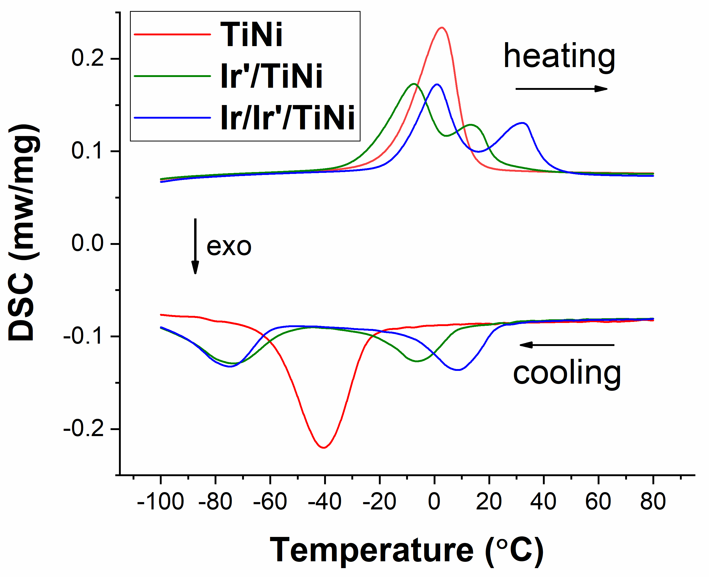
3.4. DSC Investigation of TiNi Coated with Noble Metal Films

Since the substrate to be coated is subjected to heat treatment in the reaction gas medium at the first stages of the MOCVD processes, the corresponding changes in the characteristics of TiNi phase transformations are expected. We have studied this point using the DSC method. The bare TiNi substrates exhibited a standard austenitic (heating, B19′ → B2, from −16.9 to 12.3 °C) and marstenite (cooling, B2 → B19′, from −24.8 to −62.2 °C) transitions with a small hysteresis ~7.9 °C (Figure 12).
The deposition of a compact thin iridium sublayer in a reducing atmosphere (Ir’/TiNi samples) leads a two-stage transition through the rhombohedral phase (R), e.g., B2 → R → B19′. On the heating DSC curve of Ir/TiNi (Figure 12), the peaks of the corresponding phase transformations overlap (from −26.6 to 33.3 °C), while on the cooling curve they are separated (B2 → R from 18.2 to −11.6 °C, R → B19′ from −63.3 to −96.5 °C). A shift of starting temperatures on heating and cooling towards lower values is observed. These observations are typical for heat treated TiNi alloys [8,9,10]. The appearance of the R phase after deposition of coatings in nickel-rich titanium nickelide alloys is due to the complication of the austenite structure during heat treatment with secondary phases. Secondary phases are an obstacle to the development of martensitic transformations and shift martensitic transformations to the region of low temperatures.
Further formation of a developed-columnar-iridium in an oxidizing atmosphere (Ir/Ir’/TiNi samples) shifts the phase transition temperatures towards higher temperatures: B19′ → R → B2 from −16.6 to 41.0 °C, B2 → R from 23.4 to −8.1 °C, R → B19′ from −58.8 to −90.5 °C (Figure 12). Note that the phase transition characteristics are stable over repeated heating–cooling cycles.

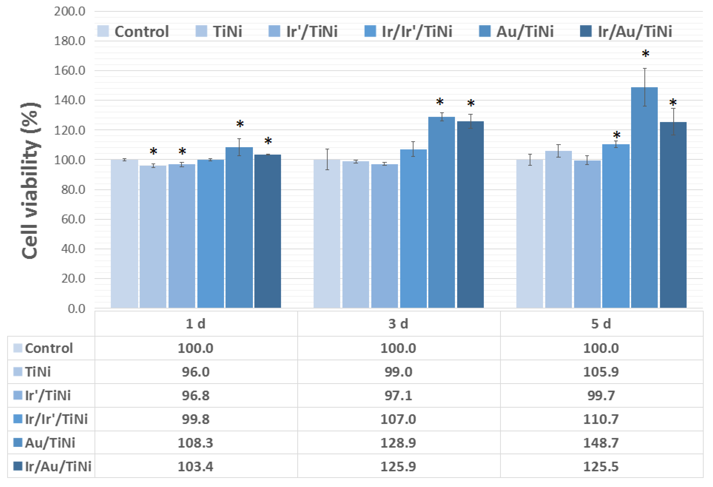
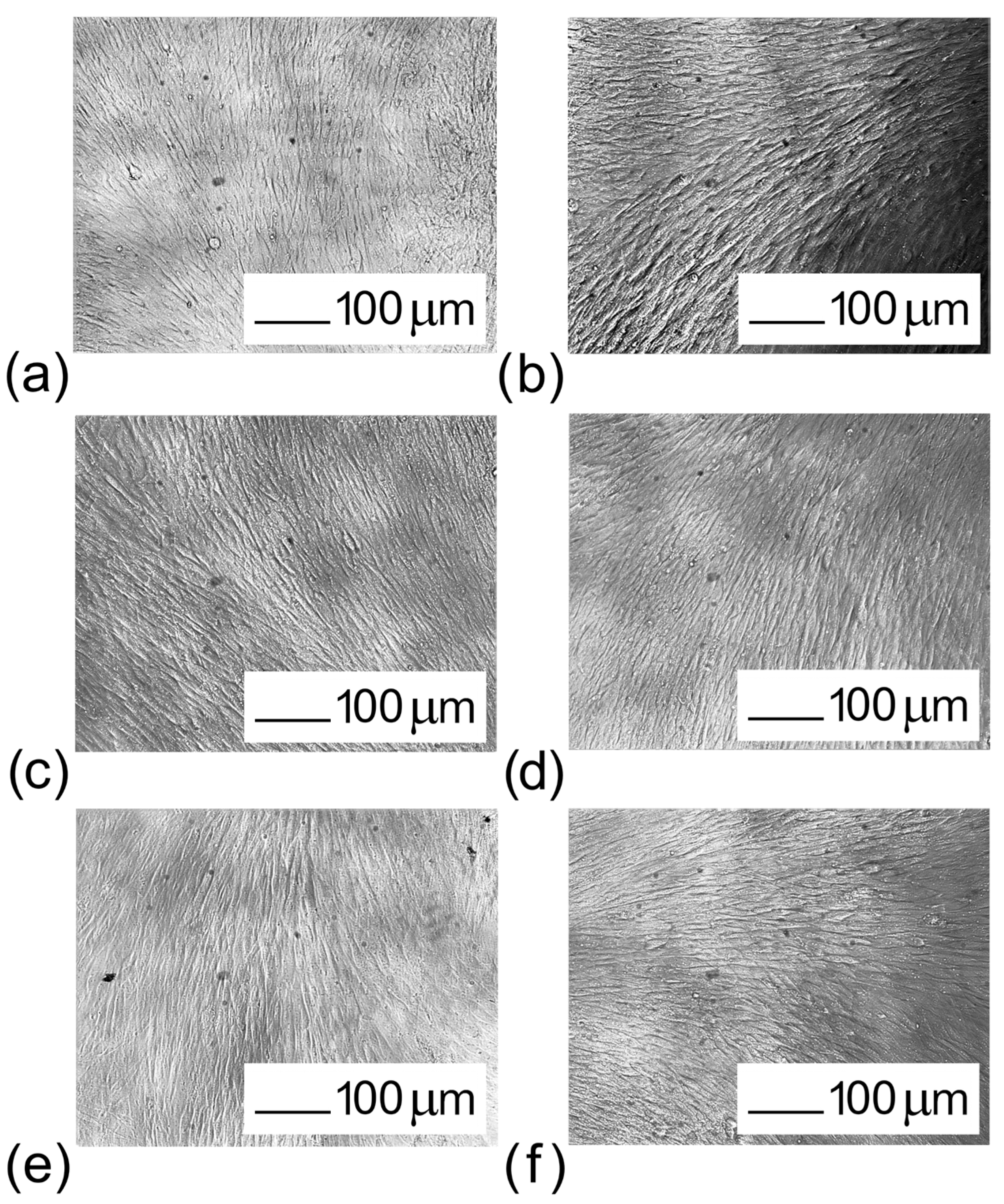
3.5. Biological Characteristics of TiNi Coated with Noble Metal Films

For primary biocompatibility assessment, a series of all-side-coated Ir’/TiNi, Au/TiNi, Ir/Ir’/TiNi and Ir/Au/TiNi samples were prepared as described above. These sample groups (5 pieces each) and original TiNi substrates were placed in a culture medium for 3 days. The resulting extracts were tested for pH, metal contents and cytotoxicity towards the sensitive Man-1 cells [74] compared to a standard culture medium as a control.
The cell viability during 1, 3 and 5 days was studied. In fact, such a period was sufficient for the almost complete cell death in the extracts obtained previously in a similar way using Ir/TiNi samples, i.e., without a compact protective Ir’ or Au sublayer [49]. In contrast, no negative effects have been observed for all the samples studied here (Figure 13). The cell morphologies and all the extracts are normal and healthy (spindle shapes), similar to that of the control group (Figure 14).
Moreover, for Au-containing samples, there is a clear trend to increase cell proliferation (Figure 13). This effect is more pronounced and constantly increases for the Au/TiNi sample (up to 150% in 5 days), while for the Ir/Au/TiNi sample the initial growth is observed (125% in 3 days), and then the number of cells remains practically unchanged. Increased proliferation in the presence of gold surfaces is quite typical. In particular, Au ions can induce the generation of reactive oxygen species (ROS), including singlet oxygen, superoxide, hydroxyl radical, various peroxides and hydroperoxides [75]. In turn, ROS serve as a signal molecule through oxidative modification of signaling proteins and at low concentrations ROS are essential participants in induction of mitogenic response [76,77]. It should be noted that small amounts of gold have been found in the corresponding extracts by ISP-OES (≤ 0.036 µg/mL). Apparently, the solution is able to diffuse through cracks and clearances between columnar dendrite agglomerates in the Ir coating (Figure 8c). A noticeable release of gold is also consistent with the presence of Au throughout the depth of the Ir coating (Figure 10). Note that a slightly increased cell proliferation is also observed for the TiNi and Ir/Ir’/TiNi sample extracts.
The safety of the samples is also confirmed by chemical studies of the extracts. In fact, the pH of the extracts differs from the culture medium by no more than 0.15 (Table 3). The content of metals (Ni and Ti) in the extracts obtained using all coated TiNi samples is comparable or lower than that for bare TiNi (Table 3). At the same time, the original Ir’ and Au sublayers more effectively prevent the release of both metals than Ir/Ir’ an Ir/Au layered systems. It can be assumed that the subsequent heat treatment during the MOCVD formation of a developed Ir coating somewhat disturbs the sublayer microstructure, but this is not critical for the overall protective function. For comparison, in the previous work for Ir/TiNi samples, the content of nickel in the extract was 0.86 µg/mL, which exceeded the toxic concentration [49,78,79].
The notably lower content of nickel (0.005 µg/mL) and titanium (0.0017 µg/mL) in the extracts obtained for sample Ir’/TiNi makes it possible to recommend this type of iridium films as protective layers for biological applications due to the compact microstructure ensuring the absence of clearances.

4. Conclusions

The work was focused on improving the protective function of film heterostructures based on noble metals for surface modification of medical implants. For this purpose, we have applied thin compact sublayers (iridium or gold), on which the antibacterial heterostructures with target developed morphology can be further formed. Titanium nickelide (TiNi) has been used here as an implant material (carrier) to test such systems for protection against nickel release causing toxic effects.
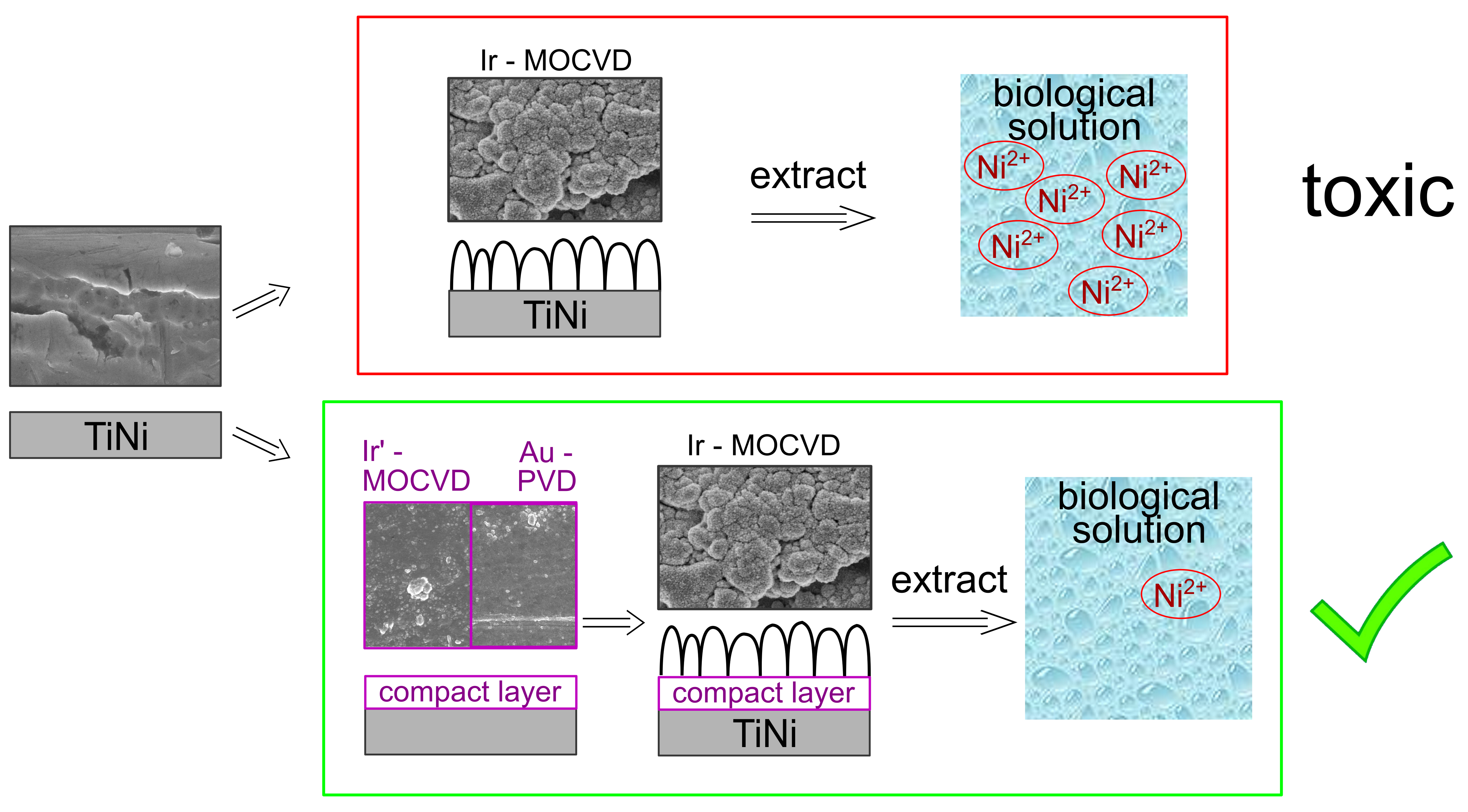
  • A new MOCVD approach to obtaining compact protective iridium layers (Ir’) is demonstrated. In fact, the usage of the Ir(CO)2(acac) precursor at relatively low temperature of 280 °C in a reducing atmosphere under VUV radiation ensure the emergence of multiple nucleation centers.
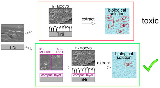
  • The application of a compact protective Ir’ or Au sublayer as thin as <100 nm effectively prevent the release of nickel and titanium from TiNi. In fact, the concentrations of metals in the culture medium extracts obtained using Au/TiNi and Ir’/TiNi are more than two times lower than for bare TiNi.
  • Application of new Ir’ protective layer is the most effective due to the absence of cracks and clearances (Ni concentration decrease by an order of magnitude, up to 0.005 µg/mL).
  • Cytotoxicity test (MAN-1 cells) confirm the high biocompatibility of the proposed noble metal film materials (cell viability ≥ 97%). Moreover, Au sublayer increases cell proliferation (cell viability ≥ 120%).
  • The protective functions of the sublayers are sufficiently preserved after the deposition of an Ir coating with a developed morphology on them by MOCVD in an oxidizing atmosphere at 350 °C. The application of the latter type of Ir coating previously stimulated increased nickel release, and accordingly, a strong cytotoxic effect on MAN-1 cells. In this work, such effects were prevented, since Ir/Ir’/TiNi and Ir/Au/TiNi sample extracts are characterized by a cell viability ≥99% with the nickel concentration <0.1 µg/mL.
The proposed protective films can be applied to other implant materials and used as sublayers for growing other nanostructures. Moreover, the efficiency of both deposition methods makes it possible to effectively adapt the combination “bottom protective sublayer–top developed coating” to specific tasks, taking into account the compatibility of materials with each other and with a carrier in terms of thermal expansion coefficients, adhesion characteristics, etc. Thus, the success of the proposed strategy expands the possibilities for the formation of antibacterial biocompatible film materials based on noble metals.

Supplementary Materials

The following supporting information can be downloaded at: https://www.mdpi.com/article/10.3390/coatings13020222/s1, Figure S1: EDX elemental mapping of TiNi coated with noble metal films: (a) Ir’/TiNi; (b) Au/TiNi; (c) Ir/Ir’/TiNi; (d) Ir/Au/TiNi; Figure S2. Typical high-resolution SEM images (magnification 400,000 and 200,000) of the surface of compact iridium layers on Si substrates (Sample 3); Figure S3. High-resolution SEM images (magnification 200,000) of the surface of noble metal films on TiNi substrates: (a) Ir’/TiNi; (b) Au/TiNi; (c) Ir/Ir’/TiNi; (d) Ir/Au/TiNi; Figure S4. High-resolution SEM images (magnification 50,000 and 200,000) of the cracks in Au layer on TiNi substrate.

Author Contributions

E.S.V.—conceptualization, writing—original draft preparation; K.I.K.—investigation (precursor synthesis and identification, coating characterization), writing—original draft preparation, visualization; I.V.K.—conceptualization, validation, investigation (powder XRD); T.P.K.—investigation (MOCVD experiments); E.V.C.—investigation (biological properties); N.B.K.—investigation (PVD experiments); A.D.F.—investigation (XPS); D.P.P.—investigation (DSC); T.Y.G.—investigation (ICP-AES); E.A.M.—investigation (SEM, EDX, cross section preparation); E.S.M.—resources, writing—review and editing; A.A.Z.—conceptualization, writing—review and editing, funding acquisition, project administration; N.B.M.—conceptualization, writing—review and editing. All authors have read and agreed to the published version of the manuscript.

Funding

The research was carried out within the state assignment of Ministry of Health of Russian Federation (theme No. 121032300337-5).

Institutional Review Board Statement

The study was conducted according to the guidelines of the Declaration of Helsinki, and approved by the by the Scientific Ethics Committee of Research Institute of Medical Genetics, Tomsk NRMC (protocol number 106; 27 June 2017).

Informed Consent Statement

Not applicable.

Data Availability Statement

Data can be provided upon request to the corresponding authors.

Acknowledgments

The authors thank the Ministry of Education and Science of the Russian Federation (projects 121031700314-5 and 121031700313-8) for access to the literature search databases and the equipment of the Collaborative Use Center to determine the film composition and morphology. Authors also thank the Tomsk State University Development Programme (Priority-2030) for the possibility for TiNi substrate production.

Conflicts of Interest

The authors declare no conflict of interest.

References

  1. Chen, Q.; Thouas, G.A. Metallic Implant Biomaterials. Mater. Sci. Eng. R Rep. 2015, 87, 1–57. [Google Scholar] [CrossRef]
  2. Li, Y.; Yang, C.; Zhao, H.; Qu, S.; Li, X.; Li, Y. New Developments of Ti-Based Alloys for Biomedical Applications. Materials 2014, 7, 1709–1800. [Google Scholar] [CrossRef] [Green Version]
  3. Valiev, R.Z.; Prokofiev, E.A.; Kazarinov, N.A.; Raab, G.I.; Minasov, T.B.; Stráský, J. Developing Nanostructured Ti Alloys for Innovative Implantable Medical Devices. Materials 2020, 13, 967. [Google Scholar] [CrossRef] [PubMed] [Green Version]
  4. Unune, D.R.; Brown, G.R.; Reilly, G.C. Thermal Based Surface Modification Techniques for Enhancing the Corrosion and Wear Resistance of Metallic Implants: A Review. Vacuum 2022, 203, 111298. [Google Scholar] [CrossRef]
  5. Elahinia, M.H.; Hashemi, M.; Tabesh, M.; Bhaduri, S.B. Manufacturing and Processing of NiTi Implants: A Review. Prog. Mater. Sci. 2012, 57, 911–946. [Google Scholar] [CrossRef]
  6. Bansiddhi, A.; Sargeant, T.D.; Stupp, S.I.; Dunand, D.C. Porous NiTi for Bone Implants: A Review. Acta Biomater. 2008, 4, 773–782. [Google Scholar] [CrossRef] [Green Version]
  7. Zhu, J.; Zeng, Q.; Fu, T. An Updated Review on TiNi Alloy for Biomedical Applications. Corros. Rev. 2019, 37, 539–552. [Google Scholar] [CrossRef]
  8. Yeung, K.W.K.; Cheung, K.M.C.; Lu, W.W.; Chung, C.Y. Optimization of Thermal Treatment Parameters to Alter Austenitic Phase Transition Temperature of NiTi Alloy for Medical Implant. Mater. Sci. Eng. A 2004, 383, 213–218. [Google Scholar] [CrossRef]
  9. Velmurugan, C.; Senthilkumar, V.; Dinesh, S.; Arulkirubakaran, D. Review on Phase Transformation Behavior of NiTi Shape Memory Alloys. Mater. Today Proc. 2018, 5, 14597–14606. [Google Scholar] [CrossRef]
  10. Chan, W.-S.; Gulati, K.; Peters, O.A. Advancing Nitinol: From Heat Treatment to Surface Functionalization for Nickel–Titanium (NiTi) Instruments in Endodontics. Bioact. Mater. 2023, 22, 91–111. [Google Scholar] [CrossRef]
  11. Lex, J.R.; Koucheki, R.; Stavropoulos, N.A.; Di Michele, J.; Toor, J.S.; Tsoi, K.; Ferguson, P.C.; Turcotte, R.E.; Papagelopoulos, P.J. Megaprosthesis Anti-Bacterial Coatings: A Comprehensive Translational Review. Acta Biomater. 2022, 140, 136–148. [Google Scholar] [CrossRef] [PubMed]
  12. Gallo, J.; Holinka, M.; Moucha, C. Antibacterial Surface Treatment for Orthopaedic Implants. Int. J. Mol. Sci. 2014, 15, 13849–13880. [Google Scholar] [CrossRef] [PubMed] [Green Version]
  13. Chouirfa, H.; Bouloussa, H.; Migonney, V.; Falentin-Daudré, C. Review of Titanium Surface Modification Techniques and Coatings for Antibacterial Applications. Acta Biomater. 2019, 83, 37–54. [Google Scholar] [CrossRef] [PubMed]
  14. Sarao, T.P.S.; Singh, H.; Singh, H. Enhancing Biocompatibility and Corrosion Resistance of Ti-6Al-4V Alloy by Surface Modification Route. J. Therm. Spray Technol. 2018, 27, 1388–1400. [Google Scholar] [CrossRef]
  15. Priyadarshini, B.; Rama, M.; Chetan; Vijayalakshmi, U. Bioactive Coating as a Surface Modification Technique for Biocompatible Metallic Implants: A Review. J. Asian Ceram. Soc. 2019, 7, 397–406. [Google Scholar] [CrossRef] [Green Version]
  16. Hussain, M.; Askari Rizvi, S.H.; Abbas, N.; Sajjad, U.; Shad, M.R.; Badshah, M.A.; Malik, A.I. Recent Developments in Coatings for Orthopedic Metallic Implants. Coatings 2021, 11, 791. [Google Scholar] [CrossRef]
  17. Yougbaré, S.; Mutalik, C.; Okoro, G.; Lin, I.-H.; Krisnawati, D.I.; Jazidie, A.; Nuh, M.; Chang, C.-C.; Kuo, T.-R. Emerging Trends in Nanomaterials for Antibacterial Applications. Int. J. Nanomed. 2021, 16, 5831–5867. [Google Scholar] [CrossRef]
  18. Na, X.; Jijiang, F.; Lingzhou, Z.; Chu, P.K.; Huo, K. Biofunctional Elements Incorporated Nano/Microstructured Coatings on Titanium Implants with Enhanced Osteogenic and Antibacterial Performance. Adv. Healthc. Mater 2020, 9, 2000681. [Google Scholar]
  19. Zhao, T.; Yang, R.; Zhong, C.; Li, Y.; Xiang, Y. Effective Inhibition of Nickel Release by Tantalum-Implanted TiNi Alloy and Its Cyto-Compatibility Evaluation in Vitro. J. Mater. Sci. 2011, 46, 2529–2535. [Google Scholar] [CrossRef]
  20. Costa, B.C.; Tokuhara, C.K.; Rocha, L.A.; Oliveira, R.C.; Lisboa-Filho, P.N.; Costa Pessoa, J. Vanadium Ionic Species from Degradation of Ti-6Al-4V Metallic Implants: In Vitro Cytotoxicity and Speciation Evaluation. Mater. Sci. Eng. C 2019, 96, 730–739. [Google Scholar] [CrossRef]
  21. Eliaz, N. Corrosion of Metallic Biomaterials: A Review. Materials 2019, 12, 407. [Google Scholar] [CrossRef] [PubMed] [Green Version]
  22. Mohammadi, H.; Muhamad, N.; Sulong, A.B.; Ahmadipour, M. Recent Advances on Biofunctionalization of Metallic Substrate Using Ceramic Coating: How Far Are We from Clinically Stable Implant? J. Taiwan Inst. Chem. Eng. 2021, 118, 254–270. [Google Scholar] [CrossRef]
  23. Beig, B.; Liaqat, U.; Niazi, M.F.K.; Douna, I.; Zahoor, M.; Niazi, M.B.K. Current Challenges and Innovative Developments in Hydroxyapatite-Based Coatings on Metallic Materials for Bone Implantation: A Review. Coatings 2020, 10, 1249. [Google Scholar] [CrossRef]
  24. Kostelac, L.; Pezzato, L.; Settimi, A.G.; Franceschi, M.; Gennari, C.; Brunelli, K.; Rampazzo, C.; Dabalà, M. Investigation of Hydroxyapatite (HAP) Containing Coating on Grade 2 Titanium Alloy Prepared by Plasma Electrolytic Oxidation (PEO) at Low Voltage. Surf. Interfaces 2022, 30, 101888. [Google Scholar] [CrossRef]
  25. Zhang, S.; Liang, X.; Gadd, G.M.; Zhao, Q. A Sol–Gel Based Silver Nanoparticle/Polytetrafluorethylene (AgNP/PTFE) Coating with Enhanced Antibacterial and Anti-Corrosive Properties. Appl. Surf. Sci. 2021, 535, 147675. [Google Scholar] [CrossRef]
  26. Liu, L.; Peng, W.; Zhang, X.; Peng, J.; Liu, P.; Shen, J. Rational Design of Phosphonate/Quaternary Amine Block Polymer as an High-Efficiency Antibacterial Coating for Metallic Substrates. J. Mater. Sci. Technol. 2021, 62, 96–106. [Google Scholar] [CrossRef]
  27. Voicu, G.; Miu, D.; Ghitulica, C.D.; Jinga, S.I.; Nicoara, A.I.; Busuioc, C.; Holban, A.M. Co Doped ZnO Thin Films Deposited by Spin Coating as Antibacterial Coating for Metallic Implants. Ceram. Int. 2020, 46, 3904–3911. [Google Scholar] [CrossRef]
  28. Guo, Y.; Xu, Z.; Wang, Q.; Zu, S.; Liu, M.; Yu, Z.; Zhang, Z.; Ren, L. Corrosion Resistance and Biocompatibility of Graphene Oxide Coating on the Surface of the Additively Manufactured NiTi Alloy. Prog. Org. Coat. 2022, 164, 106722. [Google Scholar] [CrossRef]
  29. Gunputh, U.F.; Le, H. A Review of In-Situ Grown Nanocomposite Coatings for Titanium Alloy Implants. J. Compos. Sci. 2020, 4, 41. [Google Scholar] [CrossRef] [Green Version]
  30. Basova, T.V.; Vikulova, E.S.; Dorovskikh, S.I.; Hassan, A.; Morozova, N.B. The Use of Noble Metal Coatings and Nanoparticles for the Modification of Medical Implant Materials. Mater. Des. 2021, 204, 109672. [Google Scholar] [CrossRef]
  31. Ye, L.; Cao, Z.; Liu, X.; Cui, Z.; Li, Z.; Liang, Y.; Zhu, S.; Wu, S. Noble Metal-Based Nanomaterials as Antibacterial Agents. J. Alloys Compd. 2022, 904, 164091. [Google Scholar] [CrossRef]
  32. Dowling, D.; Betts, A..; Pope, C.; McConnell, M..; Eloy, R.; Arnaud, M. Anti-Bacterial Silver Coatings Exhibiting Enhanced Activity through the Addition of Platinum. Surf. Coat. Technol. 2003, 163–164, 637–640. [Google Scholar] [CrossRef]
  33. Ryu, H.-S.; Bae, I.-H.; Lee, K.-G.; Hwang, H.-S.; Lee, K.-H.; Koh, J.-T.; Cho, J.-H. Antibacterial Effect of Silver-Platinum Coating for Orthodontic Appliances. Angle Orthod. 2012, 82, 151–157. [Google Scholar] [CrossRef] [PubMed] [Green Version]
  34. Markowska-Szczupak, A.; Paszkiewicz, O.; Michalkiewicz, B.; Kamińska, A.; Wróbel, R.J. Fabrication of Antibacterial Metal Surfaces Using Magnetron-Sputtering Method. Materials 2021, 14, 7301. [Google Scholar] [CrossRef]
  35. Cai, T.; Fang, G.; Tian, X.; Yin, J.J.; Chen, C.; Ge, C. Optimization of Antibacterial Efficacy of Noble-Metal-Based Core-Shell Nanostructures and Effect of Natural Organic Matter. ACS Nano 2019, 13, 12694–12702. [Google Scholar] [CrossRef]
  36. Ramteke, L.; Gawali, P.; Jadhav, B.L.; Chopade, B.A. Comparative Study on Antibacterial Activity of Metal Ions, Monometallic and Alloy Noble Metal Nanoparticles Against Nosocomial Pathogens. Bionanoscience 2020, 10, 1018–1036. [Google Scholar] [CrossRef]
  37. Abuayyash, A.; Ziegler, N.; Meyer, H.; Meischein, M.; Sengstock, C.; Moellenhoff, J.; Rurainsky, C.; Heggen, M.; Garzón-Manjón, A.; Scheu, C.; et al. Enhanced Antibacterial Performance of Ultrathin Silver/Platinum Nanopatches by a Sacrificial Anode Mechanism. Nanomed. Nanotechnol. Biol. Med. 2020, 24, 102126. [Google Scholar] [CrossRef]
  38. Loza, K.; Heggen, M.; Epple, M. Synthesis, Structure, Properties, and Applications of Bimetallic Nanoparticles of Noble Metals. Adv. Funct. Mater. 2020, 30, 1909260. [Google Scholar] [CrossRef] [Green Version]
  39. Breisch, M.; Loza, K.; Pappert, K.; Rostek, A.; Rurainsky, C.; Tschulik, K.; Heggen, M.; Epple, M.; Tiller, J.C.; Schildhauer, T.A.; et al. Enhanced Dissolution of Silver Nanoparticles in a Physical Mixture with Platinum Nanoparticles Based on the Sacrificial Anode Effect. Nanotechnology 2020, 31, 055703. [Google Scholar] [CrossRef]
  40. Dorovskikh, S.I.; Vikulova, E.S.; Chepeleva, E.V.; Vasilieva, M.B.; Nasimov, D.A.; Maksimovskii, E.A.; Tsygankova, A.R.; Basova, T.V.; Sergeevichev, D.S.; Morozova, N.B. Noble Metals for Modern Implant Materials: MOCVD of Film Structures and Cytotoxical, Antibacterial, and Histological Studies. Biomedicines 2021, 9, 851. [Google Scholar] [CrossRef]
  41. Dorovskikh, S.I.; Vikulova, E.S.; Sergeevichev, D.S.; Guselnikova, T.Y.; Zheravin, A.A.; Nasimov, D.A.; Vasilieva, M.B.; Chepeleva, E.V.; Saprykin, A.I.; Basova, T.V.; et al. Biological Studies of New Implant Materials Based on Carbon and Polymer Carriers with Film Heterostructures Containing Noble Metals. Biomedicines 2022, 10, 2230. [Google Scholar] [CrossRef] [PubMed]
  42. Köller, M.; Sengstock, C.; Motemani, Y.; Khare, C.; Buenconsejo, P.J.S.; Geukes, J.; Schildhauer, T.A.; Ludwig, A. Antibacterial Activity of Microstructured Ag/Au Sacrificial Anode Thin Films. Mater. Sci. Eng. C 2015, 46, 276–280. [Google Scholar] [CrossRef]
  43. Köller, M.; Bellova, P.; Javid, S.M.; Motemani, Y.; Khare, C.; Sengstock, C.; Tschulik, K.; Schildhauer, T.A.; Ludwig, A. Antibacterial Activity of Microstructured Sacrificial Anode Thin Films by Combination of Silver with Platinum Group Elements (Platinum, Palladium, Iridium). Mater. Sci. Eng. C 2017, 74, 536–541. [Google Scholar] [CrossRef] [PubMed]
  44. El Arrassi, A.; Bellova, P.; Javid, S.M.; Motemani, Y.; Khare, C.; Sengstock, C.; Köller, M.; Ludwig, A.; Tschulik, K. A Unified Interdisciplinary Approach to Design Antibacterial Coatings for Fast Silver Release. ChemElectroChem 2017, 4, 1975–1983. [Google Scholar] [CrossRef]
  45. Abuayyash, A.; Ziegler, N.; Gessmann, J.; Sengstock, C.; Schildhauer, T.A.; Ludwig, A.; Köller, M. Antibacterial Efficacy of Sacrifical Anode Thin Films Combining Silver with Platinum Group Elements within a Bacteria-Containing Human Plasma Clot. Adv. Eng. Mater. 2018, 20, 1700493. [Google Scholar] [CrossRef]
  46. Groessner-Schreiber, B.; Neubert, A.; Müller, W.-D.; Hopp, M.; Griepentrog, M.; Lange, K.-P. Fibroblast Growth on Surface-Modified Dental Implants: An in Vitro Study. J. Biomed. Mater. Res. Part A 2003, 64, 591–599. [Google Scholar] [CrossRef] [PubMed]
  47. Khalili, A.; Ahmad, M. A Review of Cell Adhesion Studies for Biomedical and Biological Applications. Int. J. Mol. Sci. 2015, 16, 18149–18184. [Google Scholar] [CrossRef] [Green Version]
  48. Souza, J.C.M.; Sordi, M.B.; Kanazawa, M.; Ravindran, S.; Henriques, B.; Silva, F.S.; Aparicio, C.; Cooper, L.F. Nano-Scale Modification of Titanium Implant Surfaces to Enhance Osseointegration. Acta Biomater. 2019, 94, 112–131. [Google Scholar] [CrossRef]
  49. Vikulova, E.S.; Karakovskaya, K.I.; Koretskaya, T.P.; Korolkov, I.V.; Chepeleva, E.V.; Asanov, I.P.; Tsygankova, A.R.; Maksimovskii, E.A.; Marchenko, E.S.; Lantsukhay, Y.A.; et al. MOCVD of Noble Metal Film Materials for Medical Implants: Microstructure and Biocompatibility of Ir and Au/Ir Coatings on TiNi. Coatings 2021, 11, 638. [Google Scholar] [CrossRef]
  50. Gunther, V.; Marchenko, E.; Chekalkin, T.; Baigonakova, G.; Kang, J.; Kim, J.; Klopotov, A. Study of Structural Phase Transitions in Quinary TiNi(MoFeAg)-Based Alloys. Mater. Res. Express 2017, 4, 105702. [Google Scholar] [CrossRef]
  51. Vikulova, E.S.; Karakovskaya, K.I.; Ilyin, I.Y.; Zelenina, L.N.; Sysoev, S.V.; Morozova, N.B. Thermodynamic Study of Volatile Iridium (I) Complexes with 1,5-Cyclooctadiene and Acetylacetonato Derivatives: Effect of (O,O) and (O,N) Coordination Sites. J. Chem. Thermodyn. 2019, 133, 194–201. [Google Scholar] [CrossRef]
  52. Zherikova, K.V.; Kuratieva, N.V.; Morozova, N.B. Crystal Structure of (Acetylacetonato) (Dicarbonyl)Iridium(I). J. Struct. Chem. 2009, 50, 574–576. [Google Scholar] [CrossRef]
  53. Karakovskaya, K.I.; Dorovskikh, S.I.; Vikulova, E.S.; Ilyin, I.Y.; Zherikova, K.V.; Basova, T.V.; Morozova, N.B. Volatile Iridium and Platinum MOCVD Precursors: Chemistry, Thermal Properties, Materials and Prospects for Their Application in Medicine. Coatings 2021, 11, 78. [Google Scholar] [CrossRef]
  54. Zamchiy, A.O.; Baranov, E.A.; Konstantinov, V.O.; Lunev, N.A.; Sakhapov, S.Z.; Korolkov, I.V.; Volodin, V.A. Activation Energy of Gold-Induced Crystallization of Amorphous Silicon Suboxide Films. Mater. Lett. 2022, 323, 132566. [Google Scholar] [CrossRef]
  55. Gates-Rector, S.; Blanton, T. The Powder Diffraction File: A Quality Materials Characterization Database. Powder Diffr. 2019, 34, 352–360. [Google Scholar] [CrossRef] [Green Version]
  56. Kraus, W.; Nolze, G. POWDER CELL—A Program for the Representation and Manipulation of Crystal Structures and Calculation of the Resulting X-ray Powder Patterns. J. Appl. Crystallogr. 1996, 29, 301–303. [Google Scholar] [CrossRef]
  57. Greczynski, G.; Hultman, L. X-ray Photoelectron Spectroscopy: Towards Reliable Binding Energy Referencing. Prog. Mater. Sci. 2020, 107, 100591. [Google Scholar] [CrossRef]
  58. Freakley, S.J.; Ruiz-Esquius, J.; Morgan, D.J. The X-ray Photoelectron Spectra of Ir, IrO2 and IrCl3 Revisited. Surf. Interface Anal. 2017, 49, 794–799. [Google Scholar] [CrossRef]
  59. Zhang, B.; Hou, Y.; Wang, X.; Wang, Y.; Geng, L. Mechanical Properties, Degradation Performance and Cytotoxicity of Mg-Zn-Ca Biomedical Alloys with Different Compositions. Mater. Sci. Eng. C 2011, 31, 1667–1673. [Google Scholar] [CrossRef]
  60. Grigor’eva, E.V.; Malankhanova, T.B.; Surumbayeva, A.; Pavlova, S.V.; Minina, J.M.; Kizilova, E.A.; Suldina, L.A.; Morozova, K.N.; Kiseleva, E.; Sorokoumov, E.D.; et al. Generation of GABAergic Striatal Neurons by a Novel IPSC Differentiation Protocol Enabling Scalability and Cryopreservation of Progenitor Cells. Cytotechnology 2020, 72, 649–663. [Google Scholar] [CrossRef]
  61. Gouveia, S.T.; Silva, F.V.; Costa, L.M.; Nogueira, A.R.A.; Nóbrega, J.A. Determination of Residual Carbon by Inductively-Coupled Plasma Optical Emission Spectrometry with Axial and Radial View Configurations. Anal. Chim. Acta 2001, 445, 269–275. [Google Scholar] [CrossRef]
  62. de Souza, R.M.; Leocádio, L.G.; da Silveira, C.L.P. ICP OES Simultaneous Determination of Ca, Cu, Fe, Mg, Mn, Na, and P in Biodiesel by Axial and Radial Inductively Coupled Plasma-Optical Emission Spectrometry. Anal. Lett. 2008, 41, 1615–1622. [Google Scholar] [CrossRef]
  63. Abelson, J.R.; Girolami, G.S. New Strategies for Conformal, Superconformal, and Ultrasmooth Films by Low Temperature Chemical Vapor Deposition. J. Vac. Sci. Technol. A 2020, 38, 030802. [Google Scholar] [CrossRef] [Green Version]
  64. Igumenov, I.K.; Gelfond, N.V.; Morozova, N.B.; Nizard, H. Overview of Coating Growth Mechanisms in MOCVD Processes as Observed in Pt Group Metals. Chem. Vap. Depos. 2007, 13, 633–637. [Google Scholar] [CrossRef]
  65. Dorovskikh, S.I.; Vikulova, E.S.; Korolkov, I.V.; Maksimovskiy, E.A.; Kal’nyi, D.B.; Morozova, N.B. Microstructure of Iridium Enriched PtxIr(1–x) Films Prepared by Chemical Vapor Deposition. J. Struct. Chem. 2021, 62, 1447–1456. [Google Scholar] [CrossRef]
  66. Vikulova, E.S.; Kal’nyi, D.B.; Shubin, Y.V.; Kokovkin, V.V.; Morozova, N.B.; Hassan, A.; Basova, T.V. Metal Ir Coatings on Endocardial Electrode Tips, Obtained by MOCVD. Appl. Surf. Sci. 2017, 425, 1052–1058. [Google Scholar] [CrossRef]
  67. Wu, S.; Liu, X.; Chan, Y.L.; Ho, J.P.Y.; Chung, C.Y.; Chu, P.K.; Chu, C.L.; Yeung, K.W.K.; Lu, W.W.; Cheung, K.M.C.; et al. Nickel Release Behavior, Cytocompatibility, and Superelasticity of Oxidized Porous Single-Phase NiTi. J. Biomed. Mater. Res. Part A 2007, 81, 948–955. [Google Scholar] [CrossRef]
  68. Tanaka, S.; Nomura, N.; Nishioka, T.; Hirotsu, M.; Nakajima, H. Synthesis of Iron(III)-Carbonyl Complex with Variable Wavelength Range for CO Release Depending on Protonation and Deprotonation of Axial Phosphorous Ligands. J. Organomet. Chem. 2021, 943, 121843. [Google Scholar] [CrossRef]
  69. Wong, M.H.; Cheng, F.T.; Pang, G.K.H.; Man, H.C. Characterization of Oxide Film Formed on NiTi by Laser Oxidation. Mater. Sci. Eng. A 2007, 448, 97–103. [Google Scholar] [CrossRef]
  70. Fotovvati, B.; Namdari, N.; Dehghanghadikolaei, A. On Coating Techniques for Surface Protection: A Review. J. Manuf. Mater. Process. 2019, 3, 28. [Google Scholar] [CrossRef] [Green Version]
  71. Panjan, P.; Drnovšek, A.; Gselman, P.; Čekada, M.; Panjan, M. Review of Growth Defects in Thin Films Prepared by PVD Techniques. Coatings 2020, 10, 447. [Google Scholar] [CrossRef]
  72. Dan, A.; Bijalwan, P.K.; Pathak, A.S.; Bhagat, A.N. A Review on Physical Vapor Deposition-Based Metallic Coatings on Steel as an Alternative to Conventional Galvanized Coatings. J. Coat. Technol. Res. 2022, 19, 403–438. [Google Scholar] [CrossRef]
  73. Kim, H.; Kim, J.; Kim, J.; Han, G.H.; Guo, W.; Hong, S.; Park, H.S.; Jang, H.W.; Kim, S.Y.; Ahn, S.H. Dendritic Gold-Supported Iridium/Iridium Oxide Ultra-Low Loading Electrodes for High-Performance Proton Exchange Membrane Water Electrolyzer. Appl. Catal. B Environ. 2021, 283, 119596. [Google Scholar] [CrossRef]
  74. Marchenko, E.; Baigonakova, G.; Yasenchuk, Y. Gradient Crystalline Coating on a Biomedical TiNi Alloy Prepared by Magnetron Sputtering and Annealing. Vacuum 2020, 181, 109652. [Google Scholar] [CrossRef]
  75. Jia, S.; Ge, S.; Fan, X.; Leong, K.W.; Ruan, J. Promoting Reactive Oxygen Species Generation: A Key Strategy in Nanosensitizer-Mediated Radiotherapy. Nanomedicine 2021, 16, 759–778. [Google Scholar] [CrossRef]
  76. Patel, R.; Rinker, L.; Peng, J.; Chilian, W.M. Reactive Oxygen Species: The Good and the Bad. In Reactive Oxygen Species (ROS) in Living Cells; InTech: Rang-Du-Fliers, France, 2018. [Google Scholar]
  77. Carvajal Carvajal, C. Reactive Oxygen Species: Training, Function and Oxidative Stress. Rev. Med. Leg. Costa Rica 2019, 36, 91–100. [Google Scholar]
  78. Das, K.K.; Reddy, R.C.; Bagoji, I.B.; Das, S.; Bagali, S.; Mullur, L.; Khodnapur, J.P.; Biradar, M.S. Primary Concept of Nickel Toxicity—An Overview. J. Basic Clin. Physiol. Pharmacol. 2019, 30, 141–152. [Google Scholar] [CrossRef] [Green Version]
  79. Buxton, S.; Garman, E.; Heim, K.E.; Lyons-Darden, T.; Schlekat, C.E.; Taylor, M.D.; Oller, A.R. Concise Review of Nickel Human Health Toxicology and Ecotoxicology. Inorganics 2019, 7, 89. [Google Scholar] [CrossRef] [Green Version]
Figure 1. Preparation of noble metal films on TiNi substrates. Compact thin sublayers are color-marked.
Coatings 13 00222 g001
Figure 2. SEM micrographs of the surfaces and cross-sections of iridium films on Si(100) substrates: (a) Sample 1; (b) Sample 2; (c) Sample 3; (d) Sample 4. Magnification 100,000 times.
Coatings 13 00222 g002
Figure 3. XRD patterns of noble metal films on TiNi substrates.
Coatings 13 00222 g003
Figure 4. The XRS depth profiles of the element concentrations for noble metal sublayers on TiNi substrates (a) Ir’/TiNi and (b) Au/TiNi.
Coatings 13 00222 g004
Figure 5. XPS spectra of Ir’/TiNi sample at different Ar+ etching times: (a) Ir 4f; (b) C 1s; (c) O 1s; (d) Ti 2p; and (e) Ni 2p.
Coatings 13 00222 g005
Figure 6. SEM micrographs of the surfaces of TiNi substrates and those coated with noble metal films: (a) bare TiNi (b) Ir’/TiNi; (c) Au/TiNi; (d) Ir/Ir’/TiNi; (e) Ir/Au/TiNi. Magnification 100,000 times (left) and 10,000 times (right). The arrows indicate examples of primary surface agglomerates.
Coatings 13 00222 g006
Figure 7. XPS spectra of Au/TiNi sample at different Ar+ etching times: (a) Au 4f; (b) C 1s; (c) O 1s; (d) Ti 2p; and (e) Ni 2p.
Coatings 13 00222 g007
Figure 8. SEM micrographs of the large surface microdefects of TiNi substrates and the noble metal films formed on them: (a) bare TiNi; (b) Au/TiNi; and (c) Ir/Au/TiNi. Magnification 1000 times (left) and 10,000 times (right, circle-marked areas). Circles mark areas captured at high magnification. The arrows indicate examples of secondary surface agglomerates (b,c) at the large surface microdefects of initial TiNi surface (a).
Coatings 13 00222 g008
Figure 9. SEM micrographs of the cross-sections of TiNi coated with iridium films: (a) Ir’/TiNi; (b) Ir/TiNi; and (c) Ir/Ir’/TiNi.
Coatings 13 00222 g009
Figure 10. The XRS depth profiles of the element concentrations for the Ir/Au/TiNi sample.
Coatings 13 00222 g010
Figure 11. XPS spectra of Ir/Au/TiNi sample at different Ar+ etching times: (a) Au 4f and Ir 4f; (b) C 1s; (c) O 1s; (d) Ti 2p; and (e) Ni 2p.
Coatings 13 00222 g011
Figure 12. DSC curves for the TiNi substrates and those all-side-coated with iridium films.
Coatings 13 00222 g012
Figure 13. Viability of Man-1 cells cultured for 1, 3 and 5 days in 100% extraction medium obtained using TiNi substrates and those coated with noble metal films: Ir’/TiNi, Au/TiNi, Ir/Ir’/TiNi and Ir/Au/TiNi samples. * p < 0.05.
Coatings 13 00222 g013
Figure 14. Micrographs of Man-1 cells cultured in the extraction media 3 days: (a) Control; (b) TiNi; (c) Ir’/TiNi; (d) Ir/Ir’/TiNi; (e) Au/TiNi; and (f) Ir/Au/TiNi.
Coatings 13 00222 g014
Table 1. Summarized information for TiNi substrates coated with noble metal film materials discussed in this work.
SampleSublayerDeveloped CoatingCharacterizationLayer Thickness (nm)
MetalDeposition MethodMetalDeposition Method
Au/TiNigoldPVD, 300 °C--XRD, SEM, XPS, cytotoxicity test *, Ni release *90 nm
(model layer on Si)
70 nm
(estimated from XPS)
Ir’/TiNiiridiumMOCVD, Ir(CO)2(acac) + H2, VUV, 280 °C--XRD, SEM, cross-section SEM, XPS, DSC *, cytotoxicity test *, Ni release *85 nm
(model layer on Si);
50 nm
(cross-section SEM)
Ir/TiNi--iridiumMOCVD, Ir(cod)(acac) + O2, 350 °CCross-section SEM (this work);
XRD, SEM, cytotoxicity test *, Ni release * [49]
800–1000 nm
(cross-section SEM)
Ir/Au/TiNigoldPVD, 300 °CiridiumXRD, SEM, XPS cytotoxicity test *, Ni release *Ir: 800–900 nm
Au: 60–80 nm
(estimated from XPS)
Ir/Ir’/TiNiiridiumMOCVD, Ir(acac)(CO)2 + H2, VUV, 280 °CiridiumXRD, SEM, cross-section SEM, XPS, DSC *, cytotoxicity test *, Ni release *Ir: 1000 nm
Ir’: 50 nm
(cross-section SEM)
* all-side-coated samples were used.
Table 2. Deposition conditions, growth rate and coating thickness of the samples of compact iridium layers on Si(100).
NoTdep. (°C)Tevap. (°C)τ (min)VUVGrowth Rate (nm/min)Layer Thickness (nm)
128080600.6740
28060+0.8350
360120+0.7185
430060120+0.5460
Table 3. Characteristics of the extracts obtained by keeping the bare TiNi samples and those coated with noble metal films in the culture medium.
Sample GrouppHNi Content (µg/mL)Ti Content (µg/mL)
Control (culture medium)7.70n.d. (0.001) *n.d. (0.0005) *
TiNi7.630.0560.0075
Ir’/TiNi7.740.0050.0017
Ir/Ir’/TiNi7.740.0400.0082
Au/TiNi7.750.0270.0036
Ir/Au/TiNi7.850.0900.018
* not determined. Limit of detection (LODs) is indicated in brackets.
Disclaimer/Publisher’s Note: The statements, opinions and data contained in all publications are solely those of the individual author(s) and contributor(s) and not of MDPI and/or the editor(s). MDPI and/or the editor(s) disclaim responsibility for any injury to people or property resulting from any ideas, methods, instructions or products referred to in the content.

