Article

Improved Corrosion Resistance Behaviour of AlSi10Mg Alloy due to Selective Laser Melting

by
Abhishek Tiwari
1,2,*,
Gaurav Singh
1 and
Rengaswamy Jayaganthan
1
1
Department of Engineering Design, Indian Institute of Technology Madras, Chennai 600036, Tamil Nadu, India
2
Department of Mechanical and Aerospace Engineering, Indian Institute of Technology Hyderabad, Kandi, Sangareddy 502284, Telangana, India
*
Author to whom correspondence should be addressed.
Coatings 2023, 13(2), 225; https://doi.org/10.3390/coatings13020225
Submission received: 25 November 2022 / Revised: 7 January 2023 / Accepted: 9 January 2023 / Published: 18 January 2023
(This article belongs to the Special Issue Investigation on Structure and Corrosion Resistance of Steels/Alloys)

Abstract

:
The corrosion behaviour of AlSi10Mg alloy produced by selective laser melting (SLM) under two different atmospheres, namely argon and nitrogen, was compared to that of AlSi10Mg alloy that had been cast. The present study demonstrates the systematic electrochemical behaviour of selective-laser-melted (SLMed) AlSi10Mg. Potentiodynamic polarisation and electrochemical impedance spectroscopy (EIS) were used to investigate the electrochemical behaviour, illustrating the degrading features of SLMed AlSi10Mg alloy in 0.1 M NaCl solution. The corrosion resistance of AlSi10Mg produced using selective laser melting was found to be 2–3 times greater than that of AlSi10Mg that had been cast. The degradation behaviour was also explained by SEM analysis of the corroded samples of SLMed AlSi10Mg and as-cast AlSi10Mg alloy. It may be deduced that the better corrosion resistance of AlSi10Mg produced through selective laser melting is due to the fast cooling rate associated with the solidification of AlSi10Mg alloy fabricated through selective laser melting, compared with the slow cooling rate associated with the solidification of AlSi10Mg produced by casting.

1. Introduction

Additive manufacturing has emerged as a promising technique to manufacture complex structures using metallic, ceramic and polymeric materials [1]. Selective laser melting (a type of additive manufacturing) is an advanced manufacturing technique wherein the production of a part is built layer-by-layer by rastering a high-powered laser as directed by a computer-aided design (CAD) model [2]. The corrosion of additively manufactured alloy is a very important aspect of applications, e.g., in marine industries. It is important to look at the effect of microstructural features such as porosity, grain structures, dislocation networks, residual stress, solute segregation and surface roughness on the corrosion behaviour of additively manufactured alloys [3]. AlSi10Mg alloy [4,5,6,7,8,9,10] and AlSi12 alloy [11] are the most-utilised Al alloys for research on the corrosion of additively manufactured Al alloys. Si-containing aluminium alloys are frequently used due to their castability, low shrinkage and relatively low melting point [12,13,14,15,16]. Hypoeutectic AlSi10Mg alloys are used in automotive, aerospace and marine industries due to their high specific strength, low density, low thermal diffusion coefficient and low cost of reclamation [17].
AlSi10Mg has a microstructure that is made up of an α-Al phase, eutectic Si particles and secondary phases such as Mg2Si (β-phase). According to earlier investigations, the mechanical properties of AlSi10Mg alloy are degraded by eutectic Si particles with coarse and acicular morphology [18,19,20]. As a result, it is crucial to alter the microstructure of AlSi10Mg alloy in order to enhance its mechanical properties. A more refined microstructure and uniform distribution of eutectic Si particles may be achieved by quick solidification at a cooling rate of 106 °C/s (in case of selective laser melting) [21]. However, the cooling rate during casting is about 100 °C/s [22], which is less than the cooling rate of 106 oC/s in the case of additive manufacturing. Therefore, selective laser melting can be an alternative approach to achieving a cooling rate as fast as 106 °C/s for the refined microstructure and uniform distribution of eutectic Si particles [23]. Corrosion properties play a significant role in the industrial application of additively manufactured materials [24]. Literature indicates that SLMed aluminum alloys demonstrate better corrosion resistance than that of as-cast aluminum alloys [25]. According to several studies, the corrosion properties of additively manufactured samples were improved due to the homogenous microstructure and the lack of iron-based intermetallics [4,7,24], whereas other studies revealed a decline in the corrosion performances due to the reduced protection of the passive layer [9,24,26]. Rafieazad et al examined how friction stir processing affected the microstructure and the electrochemical stability of L-PBF AlSi10Mg in aerated 3.5 wt. % NaCl electrolyte [27]. The positive shift of the pitting potential and decrease in the corrosion rate and corrosion current density were evidence of improved corrosion performance of the additively manufactured sample utilising friction stir processing [27]. Damborenea et al. performed a corrosion study on additively manufactured AlSi10Mg and found similar corrosion resistance compared to as-cast AlSi10Mg [28]. Zakay et al. showed an improvement in corrosion resistance after heat treatment at 200 °C for 2 h of SLMed AlSi10Mg alloy due to a relieving of residual stresses and fine Si particles within the aluminum matrix [29]. Girelli et al. showed that T6 heat treatment on AlSi10Mg additively manufactured alloy is beneficial for corrosion resistance due to the formation of homogenised microstructure [30], while Kubacki et al. [31] and Gu et al. [16] found a decrease in corrosion resistance in heat-treated SLMed AlSi10Mg alloys. Cabrini et al. showed that building direction has no effect on additively manufactured AlSi10Mg alloy [32].
Very limited research has been conducted on how alloys made by the additive manufacturing process behave when exposed to corrosion [33]. Recent research on the corrosion behaviour of SLMed AlSi10Mg alloys has been quite limited [4-10,33]. The current study used potentiodynamic polarisation and electrochemical impedance spectroscopy to the study the corrosion behaviour of SLMed AlSi10Mg compared to as-cast AlSi10Mg. The effects of the environment and build direction on the corrosion resistance of additively manufactured AlSi10Mg alloy were also revealed by this investigation. It was hypothesised in this study that SLMed AlSi10Mg will provide better corrosion resistance due to its fine grain morphology compared to as-cast AlSi10Mg alloy.

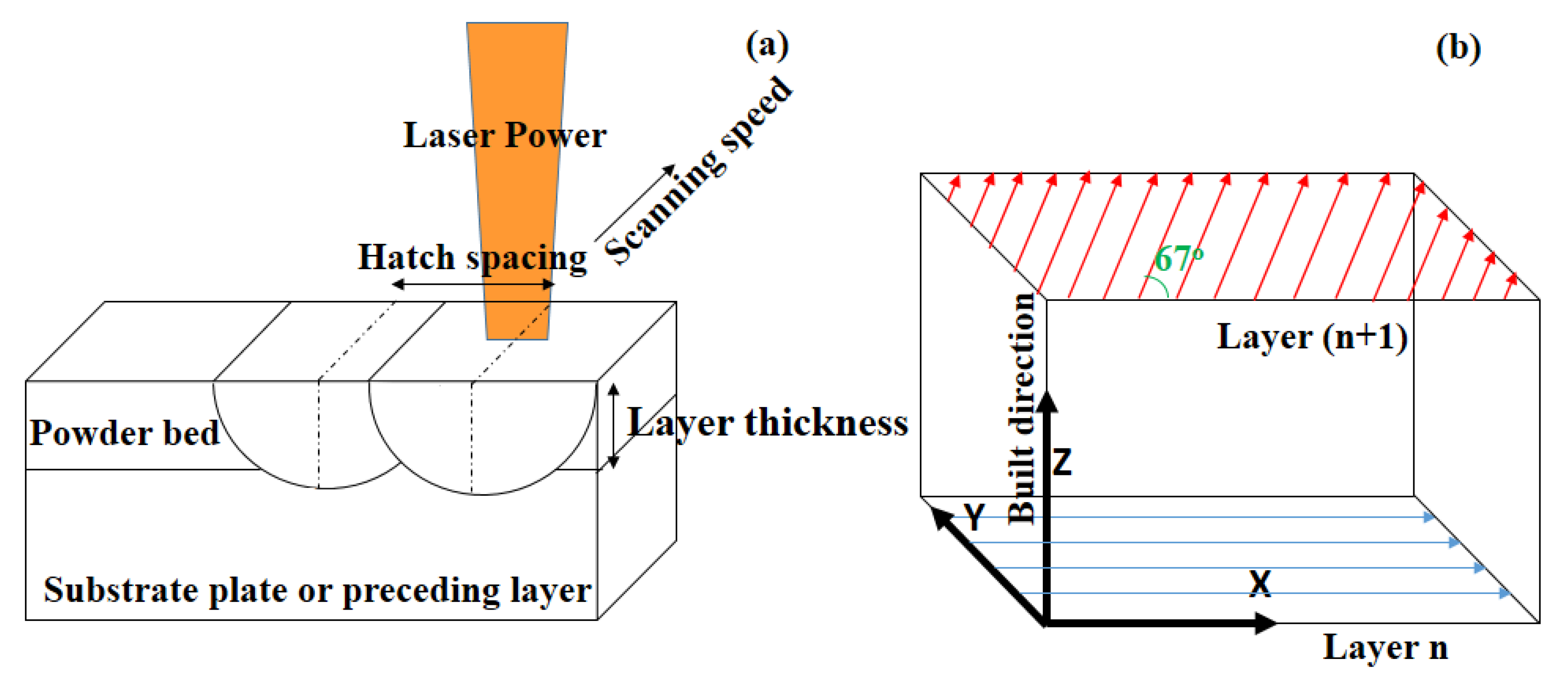
2. Materials and Experimental Procedures

Hypoeutectoid AlSi10Mg alloy powder was used to create additively manufactured samples using EOS M280 DMLS with the following parameters: laser power was 370 W, scan speed was 1300 mm/s, hatch spacing was 0.19 mm and layer thickness was 30 µm as indicated in reference [34] (Figure 1a). The AlSi10Mg specimens were printed in small rectangular blocks of the following sizes: 10 mm (x) × 8 mm (y) × 100 mm (z) and 100 mm (x) × 8 mm (y) × 10 mm (z). Vertically built samples are those with the dimensions of 10 mm × 8 mm × 100 mm, while horizontally built samples were those with dimensions of 100 mm × 8 mm × 10 mm. The samples were built layer-by-layer on a substrate that had been preheated to 300 °C. The first layer was built along the X direction and subsequent layer directions were rotated 67° after each scan (Figure 1b). The procedure was carried out in a protective environment of shielding gases, argon and nitrogen, while maintaining the same flow rate, pressure and other processing parameters. The SLMed AlSi10Mg alloy samples were made vertically and horizontally. These four SLM conditions were designated as follows: (i) under argon horizontally built, (ii) under argon vertically built, (iii) under nitrogen horizontally built and (iv) under nitrogen vertically built.
The as-cast samples of coupon size 25 mm × 25 mm × 6 mm were received from JiangyinMaideli Advanced Materials Co. Ltd., Jiangsu, China.
The chemical composition of as-cast AlSi10Mg alloys is shown in Table 1.

2.1. Microstructural Analysis

The optical microstructure of the samples was characterised using a Carl Zeiss optical microscope (Zeiss, Jena, Germany). The sample surfaces were ground using SiC sheets in the following grit sizes: 320, 800, 1200, 2000, and 2500. This was undertaken in order to characterise the samples using the optical microscope and SEM/EDS. The samples were then polished using diamond particles sized 3 µm and 1 µm. The samples were etched using Kallings reagent (5 mL of CuCl2 + 100 mL of Hydrochloric acid and 100 mL of Ethanol) following diamond polishing to observe the microstructural features.

2.2. X-ray Diffraction for Phase Identification

Phase identification was performed on the SLMed alloy under the four conditions and the as-cast AlSi10Mg alloy using a Bruker a D8 Discover AXS Powder X-ray diffractometer. The diffraction peak analysis was carried out with the aid of X’pertHighscore Plus software.

2.3. Electrochemical Characterisation

The electrochemical tests in 0.1 M NaCl were undertaken to evaluate the corrosion resistance of samples. A three-electrode cell was used for all of the electrochemical testing (the sample with an exposed area of 0.385 cm2 acted as a working electrode, the platinum wire worked as a counter electrode, and the saturated calomel electrode worked as a reference electrode). Ecorr vs. time graphs were created after immersion in 0.1 M NaCl for 30 min to determine the stabilised open-circuit potential (OCP).
SLMed AlSi10Mg and as-cast AlSi10Mg samples were polished with emery paper of up to 2500 grade and cleaned with acetone and allowed to air dry.

2.3.1. Potentiodynamic Polarisation Tests

The cathodic and anodic plots were created by sweeping the potential on either side of the OCP at a scan rate of 0.5 mV/s for the SLMed and as-cast AlSi10Mg alloy samples. The sweeping of potential was carried out over the potential range of −300/+300 mV wrt OCP for SLMed and as-cast AlSi10Mg samples.

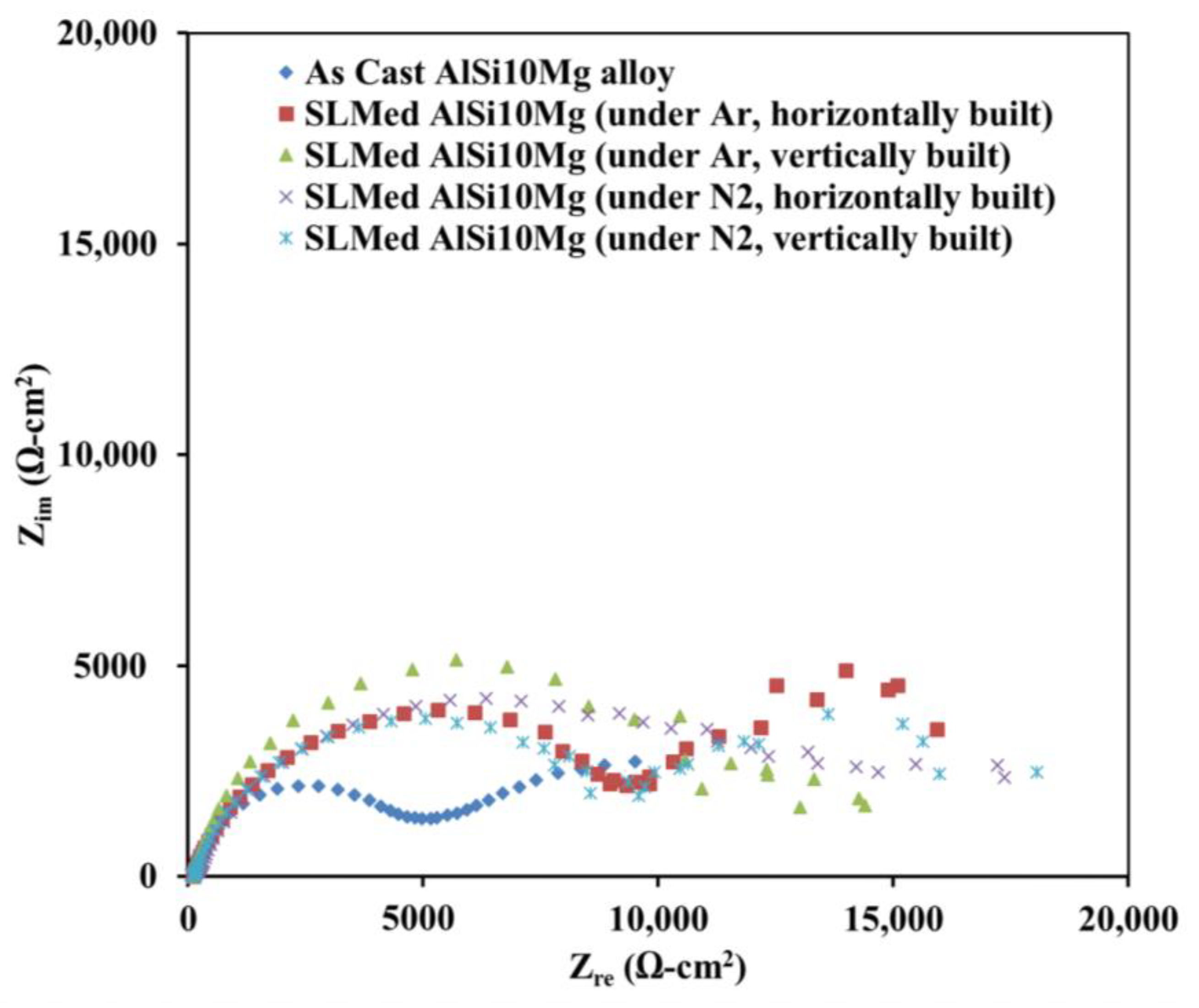
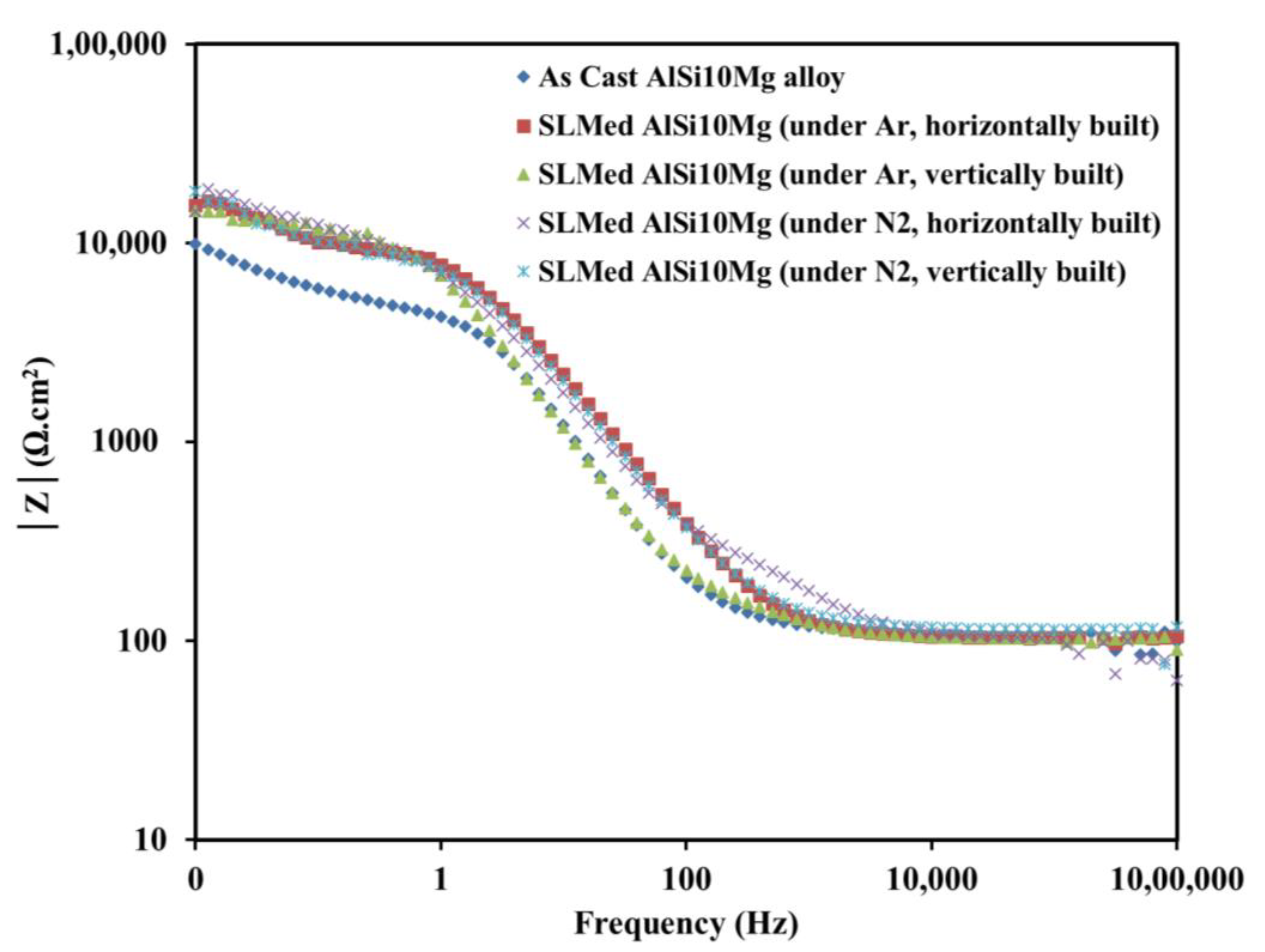
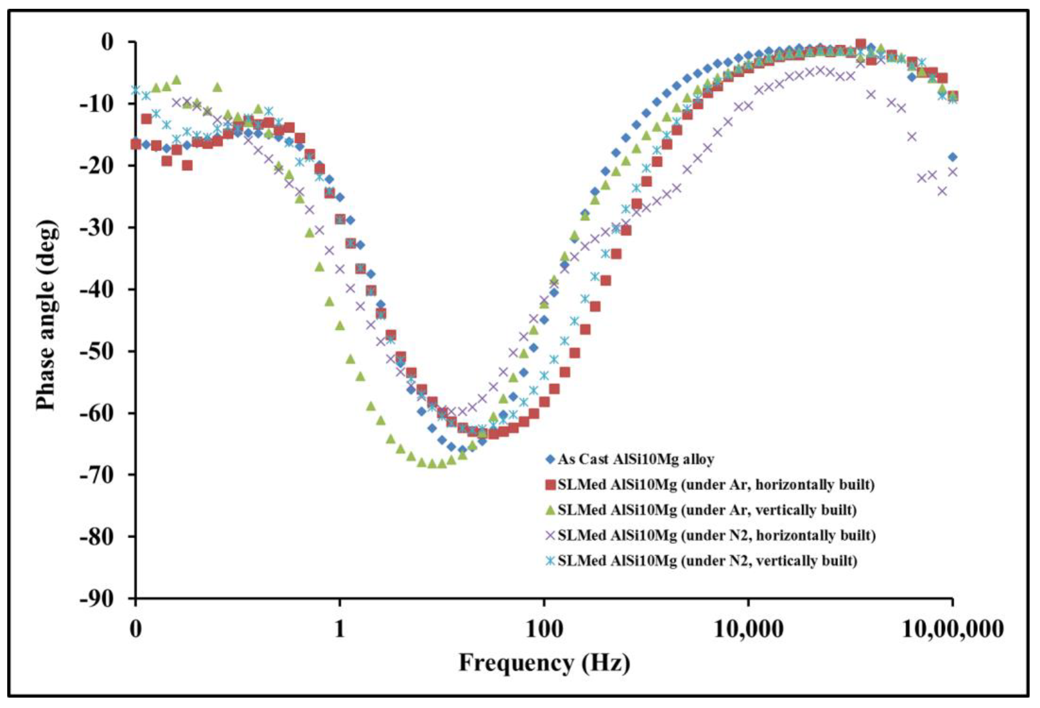
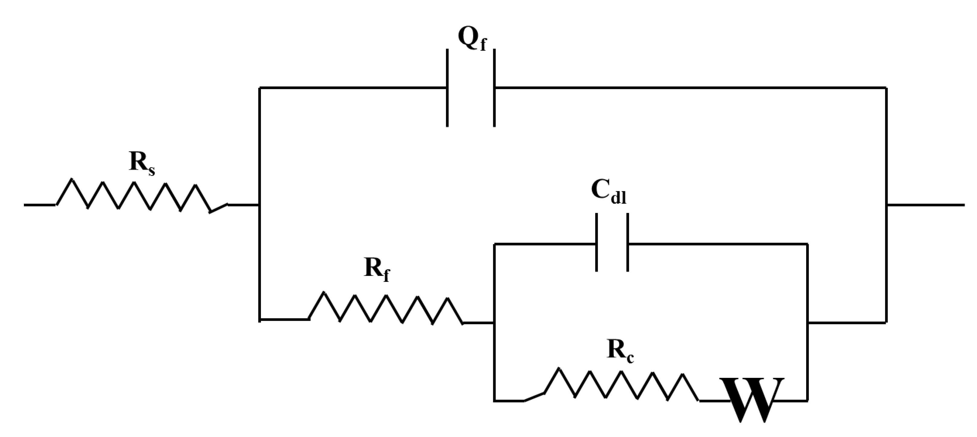
2.3.2. Electrochemical Impedance Spectroscopy (EIS)

SLMed and as-cast AlSi10Mg samples were subjected to electrochemical impedance spectroscopy (EIS) in 0.1 M NaCl solution using GAMRY reference 600+ potentiostat and an electrochemical cell with three electrodes. The Ecorr vs time plots were created after immersion in 0.1 M NaCl solution for 30 min to ascertain the stabilised open-circuit potential (OCP). For the purpose of EIS studies, the condition was deemed stable when the OCP fluctuation remained within 10 mV during a period of 1000 s. EIS tests were performed by applying a sinusoidal signal at Ecorr with a perturbation potential of 10 mV. Gamry Instruments Framework software (version 7.07) was used to measure the impedance response at frequencies ranging from 1 MHz to 10 mHz, capturing 10 points per decade of frequency. These frequencies were selected so that they reached the asymptotic limits where the imaginary impedance tends to be zero at the lowest and highest frequencies of the employed frequency range.

2.4. Post Corrosion Morphology

The post-corrosion morphology of the SLMed AlSi10Mg alloy under different conditions and the as-cast AlSi10Mg alloy after a 30 min immersion in 0.1 M NaCl followed by potentiodynamic polarisation test and removing corrosion products was inspected using SEM to study the localised corrosion response. The scanning electron microscope (SEM) with energy-dispersive spectroscopy was used to capture the SEM images.

3. Results and Discussion

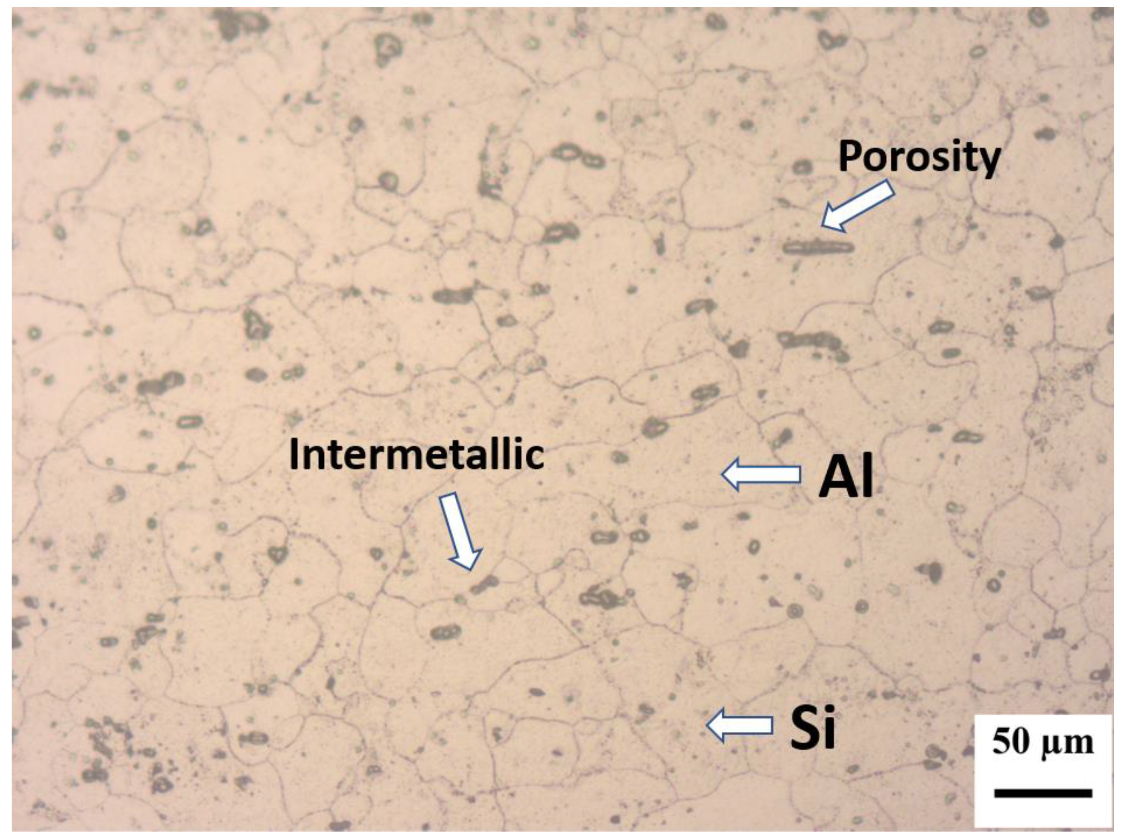
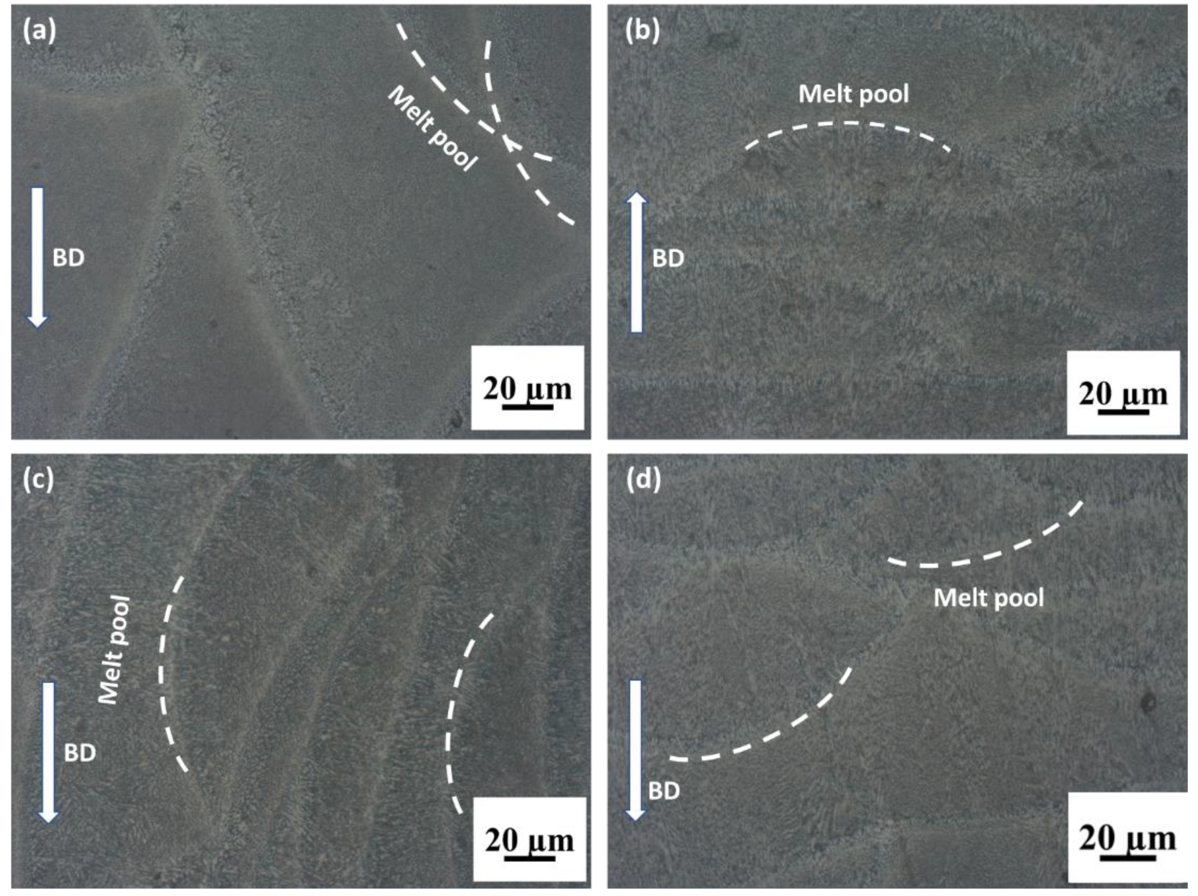
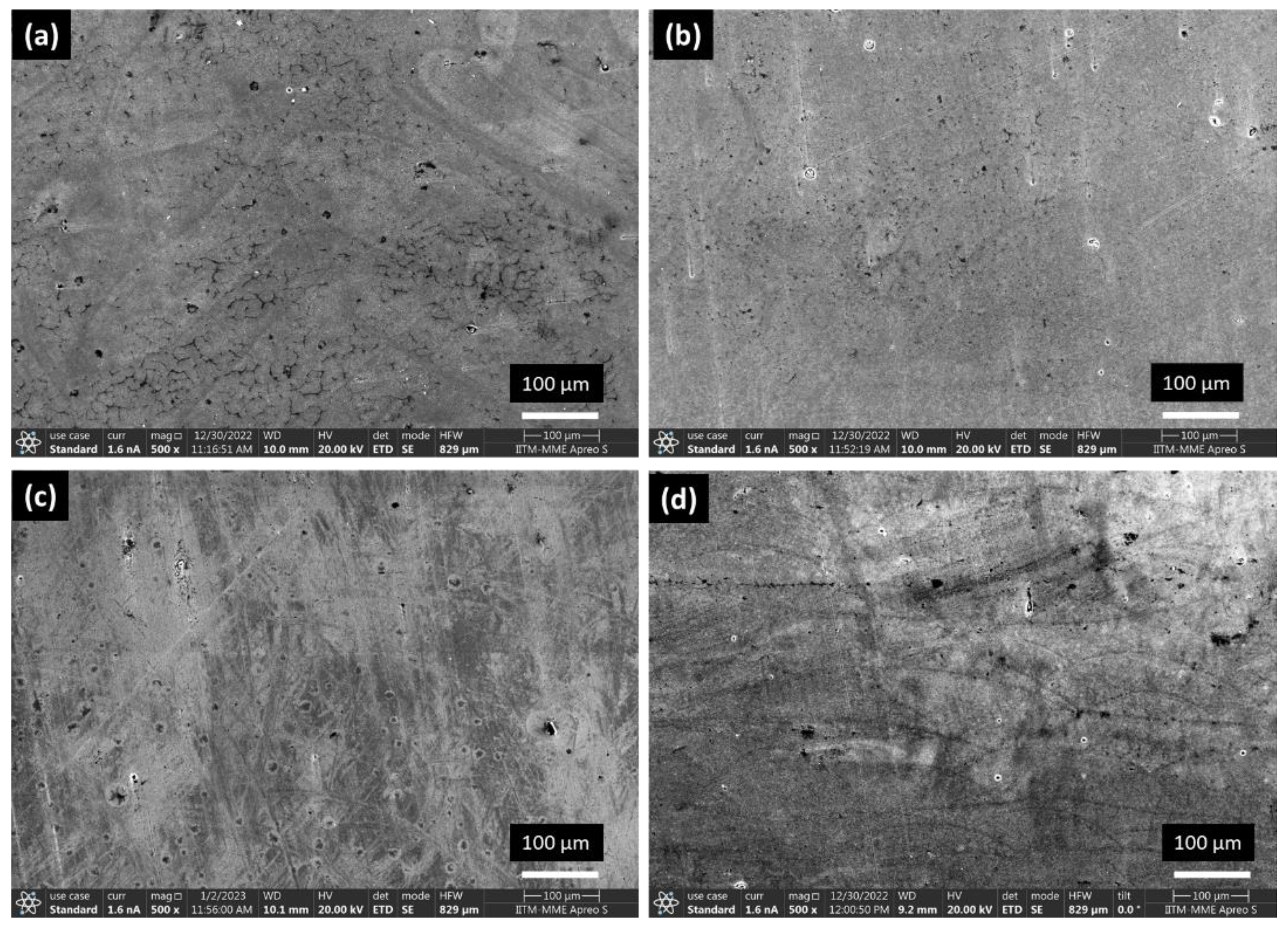
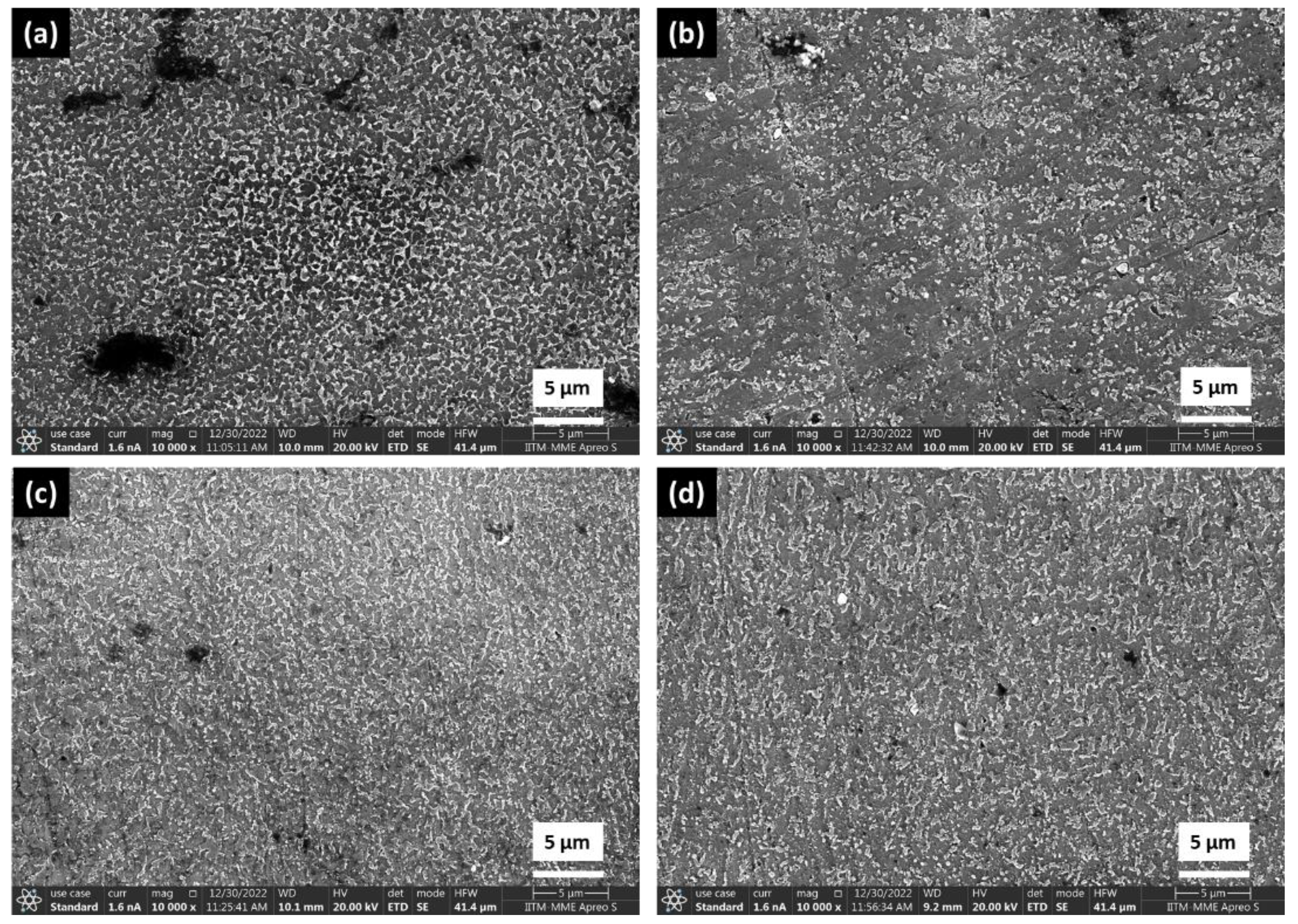
3.1. Microstructural Analysis

The selective laser-melted AlSi10Mg alloy was characterised using optical microscopy to reveal the structure through a layer-by-layer process. The microstructures of the as-cast AlSi10Mg alloy and SLMed AlSi10Mg alloy in four conditions are shown in Figure 2 and Figure 3, respectively. Figure 2 shows an optical micrograph of as-cast AlSi10Mg showing the Al matrix embedded with Si and MnFe4Al12Si2 intermetallic and some porosity. The MnFe4Al12Si2 intermetallic was also confirmed through XRD analysis. In the horizontally built sample (Figure 3a,c), the top surface (XY plane) showed the scan track features (the width of the scan tracks is about 150–200 μm). These tracks are signature features in samples manufactured by selective laser melting. The top surface (XY plane) also showed that scan path features were at an angle equal to 67°. The two Z planes (Figure 3b,d) showed a similar meso-structure of semi-circular melt pool layers (thickness of 30–100 μm). The meso-structures on the corresponding planes in the horizontally built samples were similar to the vertically built samples. The difference between the horizontally and vertically built samples was that the scanning surface was smaller in the case of the vertically built sample.
Figure 4a,b show the SEM micrographs of as-cast AlSi10Mg alloy at 1800× and 30,000× magnification. Figure 5a–d show the SEM micrographs of the SLMed AlSi10Mg alloy in four conditions at 500× magnification. For the SLMed counterparts, the microstructure consisted of overlapped melt pools (Figure 5a–d), which is due to the progressive laser rastering which causes melting and solidification of successive layers of materials. Within the melt pools, a very fine dendritic structure of the α-Al matrix bounded by the eutectic Si phase developed. Figure 6a–d show the SEM micrographs of the SLMed AlSi10Mg alloy in four conditions at 10,000× magnification. The extremely high cooling rates involved in selective laser melting caused a strong microstructural refinement. The additive manufactured (as-built) AlSi10Mg parts consisted of a fine network of Si particles inside the aluminum matrix as shown in Figure 6a–d. Microstructural refinement may therefore be the cause of the improvement of the corrosion resistance of the as-built SLMed AlSi10Mg specimens when compared with their cast counterparts. Microstructure refinement could be observed at 10,000 x SEM micrographs (Figure 6a–d).

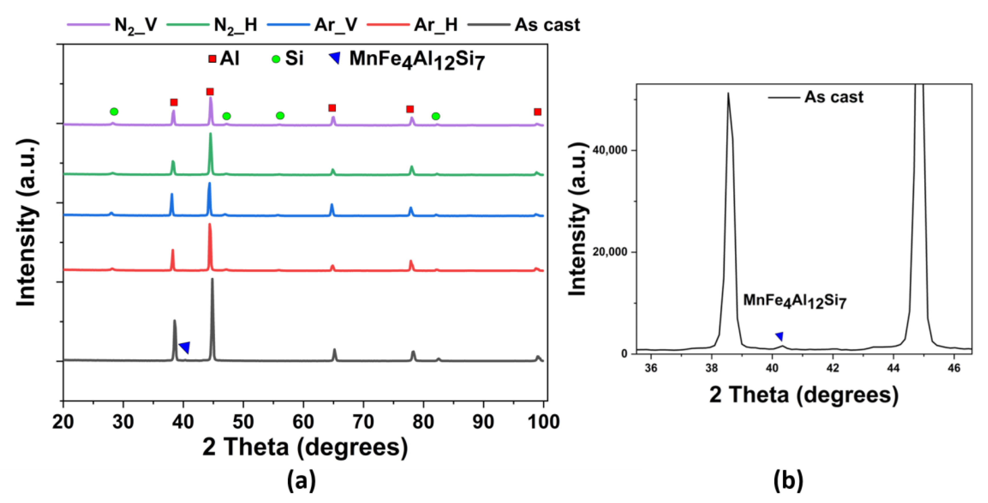
3.2. X-ray Diffraction for Phase Identification

An XRD analysis was undertaken in order to clearly distinguish between the phases that were present in the material in the SLMed AlSi10Mg alloy and the as-cast AlSi10Mg alloy. Figure 7a shows the 2θ peaks of each of the four conditions of the SLMed AlSi10Mg samples as well as the as-cast AlSi10Mg. A zoom of the XRD plot for as-cast AlSi10Mg showing MnFe4Al12Si2 is depicted in Figure 7b.
The SLMed AlSi10Mg alloy exhibited Al and Si peaks in XRD plots in all four conditions, namely under nitrogen vertically built, under nitrogen horizontally built, under argon vertically built and under argon horizontally built. The as-cast AlSi10Mg alloy also exhibited Al, Si and MnFe4Al12Si2 peaks in the XRD plot. The varied intensities were connected to the inherent epitaxial solidification characteristics of the SLMed alloy.

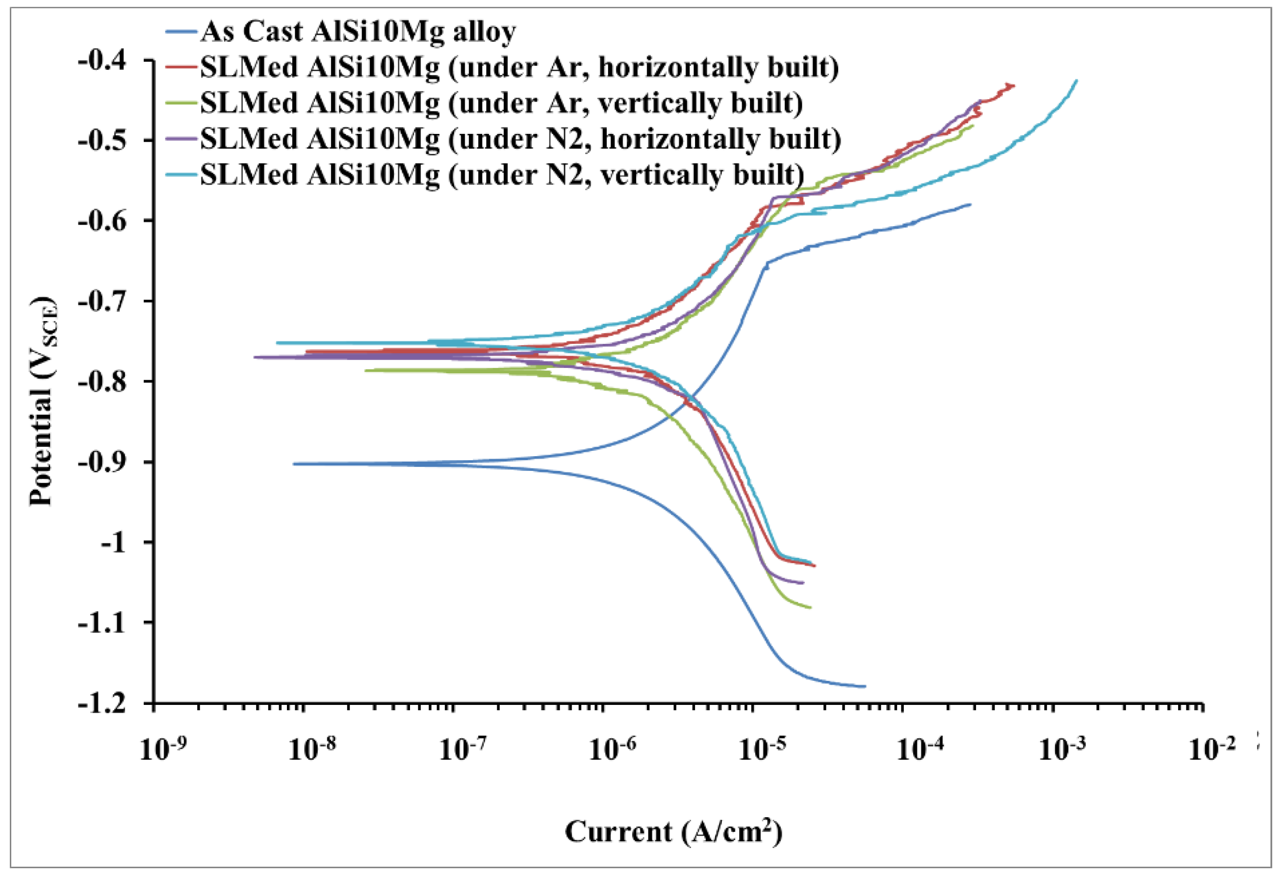
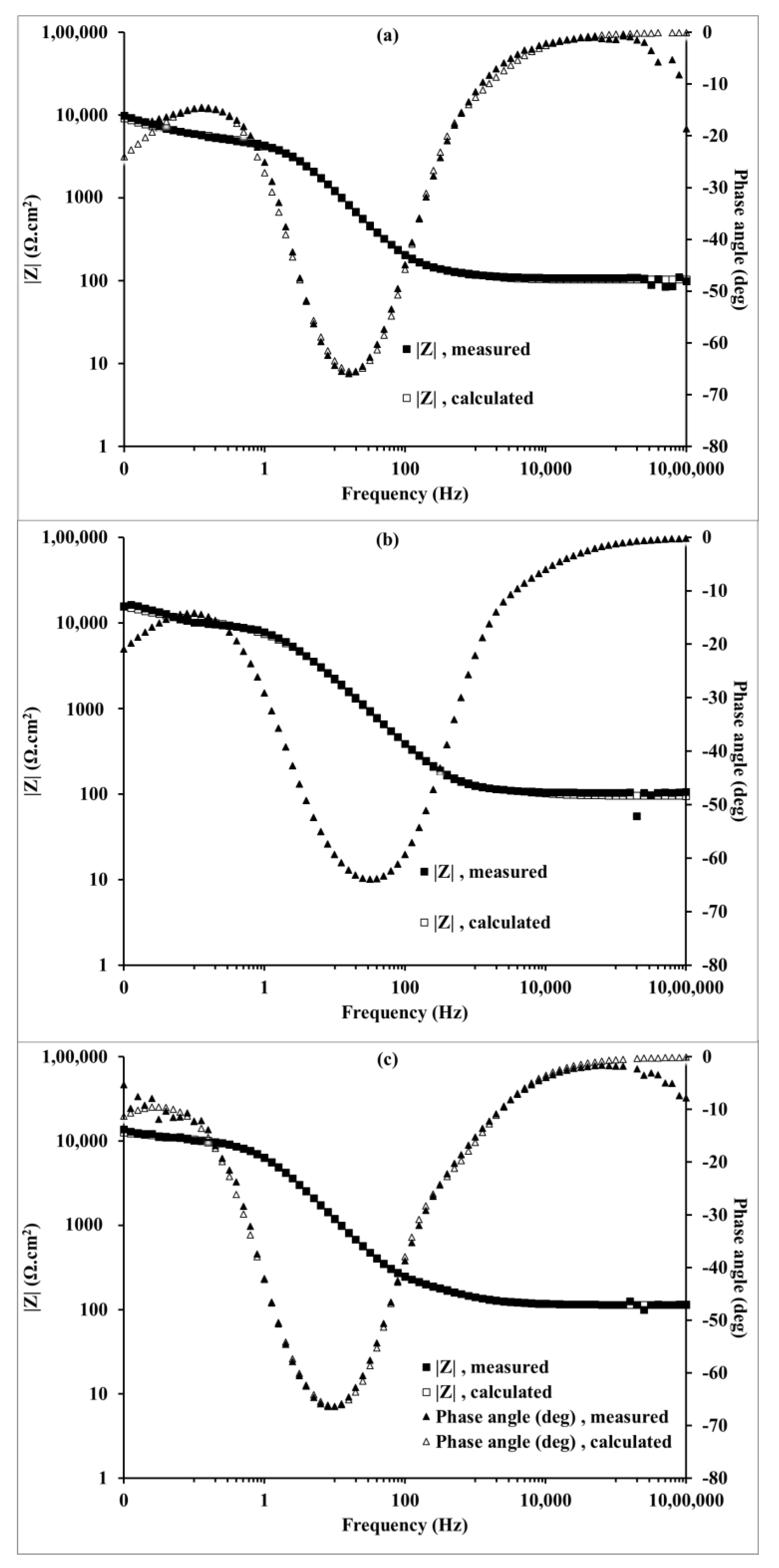
3.3. Electrochemical Characterisation

The corrosion potential (Ecorr) of the SLMed AlSi10Mg alloys (different conditions) was approximately 120–150 mV higher than that of the as-cast AlSi10Mg alloy (Figure 8). Since Ecorr is the measure of corrosion susceptibility, a positive shift in Ecorr suggests that the samples made by the additive manufacturing process have better corrosion resistance compared with that of as-cast samples. The corrosion current densities (icorr) of both of the SLMed AlSi10Mg alloys were found to be 2–3 times lower than that of the as-cast AlSi10Mg alloy, indicating a 2–3-fold improvement in corrosion resistance. The modest rise in the applied potential caused a fast increase in the anodic current demonstrating pitting corrosion characteristics, which was more prominent for the as-cast AlSi10Mg alloy sample than for the additively manufactured AlSi10Mg alloy sample, as shown in the anodic branch of the Tafel plots in Figure 8. The values of Epit-Ecorr for SLMed AlSi10Mg (under Ar, horizontally built) and as-cast samples were found to be approximately 173 mV and 243 mV, indicating a narrow passive region above the corrosion potential. Similar behaviour was observed for the other conditions of the SLMed AlSi10Mg alloys. Therefore, for definite conclusions regarding improvement in corrosion resistance, EIS studies were performed in addition to potentiodynamic polarisation.
Electrochemical impedance spectroscopy (EIS) was used to examine the stability of the protective passive layer on the SLMed AlSi10Mg alloy and the as-cast AlSi10Mg alloy after 30 min of immersion in 0.1 M NaCl solution. The magnitude of impedance at the lowest frequency in a Bode impedance plot and the diameter of the semicircle in a Nyquist plot are broad measures of the corrosion resistance. The Nyquist and Bode plots of SLMed AlSi10Mg under different conditions and the as-cast AlSi10Mg alloy (Figure 9 and Figure 10) demonstrate that the corrosion resistance of the SLMed AlSi10Mg alloy was 2–3 times better. The Bode phase plots for SLMed alloys under different conditions and as-cast AlSi10Mg after 30 min of immersion in 0.1 M NaCl solution are shown in Figure 11. The broad-phase angle troughs (minima, as phase angle values are negative) suggest a merger of two time constants in all conditions. The two time constants are related to corrosion products/solution interface and metal/solution interface. The presence of two time constants is determined by the broader nature of phase angle plots, because when two narrower peaks related to two time constants merged in phase angle plots, there was a formation of a broader peak in the phase angle plot.
A simulation of experimental EIS data was performed to quantitatively evaluate the characteristic parameters such as capacitance, charge transfer resistance and pore resistance, etc., using an appropriate equivalent electrical circuit (EEC) and a speculative corrosion mechanism. An appropriate EEC with two time constants and a Warburg element is shown in Figure 12. The time constant related to the corrosion products/solution interface is in the high-frequency range, while the time constant related to the metal/solution interface is in the lower-frequency zone.
The interconnectedness of the corrosion products on the metal surface in contact with the solution led to the selection of the EEC shown in Figure 12. In the EEC, Rs stands for the solution resistance; Qf and Rf are the constant phase element (CPE) and the pore resistance in parallel combination to represent corrosion products, respectively; Cdl is electrical double-layer capacitance; Rc is the charge transfer resistance; and W is the Warburg element. Most of the credit for the CPE conduct is given to electrode porosity, roughness and distributed surface reactivity. The impedance analysis was conducted using the Gamry Echem Analyst package for Windows. Table 2 lists the characteristic EEC parameters. Low values of χ2 goodness of fit suggests that the proposed EEC fits well with the experimental data. Charge transfer resistance is the resistance in moving an electron out of a molecule in an electrolytic solution and onto a molecule in an anode. The degree of the Warburg diffusion resistance, which represents the diffusion of corrosive solution, is the same under all conditions.
Table 2 shows that the corrosion resistance of the selective laser melted (SLMed) AlSi10Mg alloys, the sum of pore resistance (Rf) and the resistance offered by the metal/electrolyte interface (Rc) was 9.57 × 10³ Ω cm2, 12.1 × 10³ Ω cm2, 15.9 × 10³ Ω cm2 and 10.3 × 10³ Ω cm2 for under Ar horizontally built, under Ar vertically built, under N2 horizontally built and under N2 vertically built samples, respectively, and that of the as-cast AlSi10Mg alloy was 4.74 × 10³ Ω cm2. The data in Table 2 support the assertion that selective laser melted (SLMed) AlSi10Mg alloys in various conditions provide a 2–3 times improvement in corrosion resistance, and this improvement in corrosion resistance is supported by Bode impedance graphs in Figure 10. The lower chi-squared value denotes the tolerable accuracy of EEC parameters determined by EIS data simulation. The close fit of simulated EIS data with the experimental data of as-cast and selective laser melted AlSi10Mg under Ar, horizontally built condition and under N2, vertically built condition is shown in Figure 13a–c. The experimental data fit well with the simulated data in the frequency range 1,000,000 Hz to 0.01 Hz, as shown in Figure 14. The validity of the employed EEC (Figure 12) and the corrosion mechanism for as-cast and selective laser melted AlSi10Mg alloys was confirmed by the associated low chi-squared value and low errors in the EEC parameters.

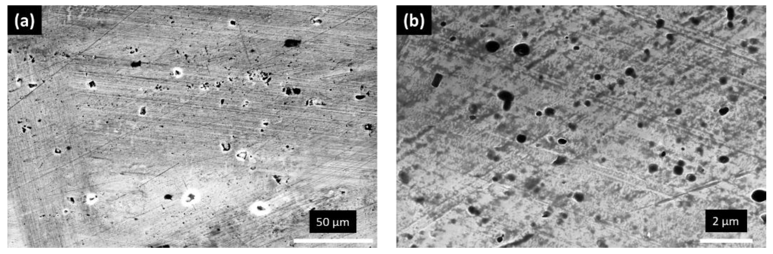
3.4. Post Corrosion Morphology

Figure 14a–d show the corrosion morphology of the SLMed AlSi10Mg alloy under different conditions and as-cast AlSi10Mg alloy after a 30 min immersion in 0.1 M NaCl followed by a potentiodynamic polarisation test and after removing corrosion products. There was more global corrosion for the as-cast alloy, but pitting corrosion was more pronounced for the SLMed AlSi10Mg alloy.
The corrosion behaviour of additively manufactured alloys differed from that of as-cast alloys due to specific conditions associated with the AM process such as layer-to-layer solidification associated with small melt pools and higher cooling rates. From a microstructure point of view, AM alloys showed fine structures as compared with cast alloys (which showed large silicon precipitates with a needle shape in the aluminum matrix), while the fine silicon precipitates formed a three-dimensional network at the grain boundaries and enclosed the aluminum matrix. These large connected silicon precipitates, which are present near or at the melt pool boundary (as shown in Figure 3a–d), decelerated the corrosion, leading to a lower corrosion rate compared with that of the as-cast AlSi10Mg alloy. The microstructure has a great influence on the corrosion resistance of the SLMed AlSi10Mg alloy, and by tailoring the microstructure, it is possible to increase the corrosion resistance in this alloy [35]. The EIS data analysis showed a higher (Rf + Rc) value for the SLMed AlSi10Mg alloys compared with the as-cast alloy (as shown in Table 2), which provide a less defective, more compact and more protective oxide layer on AM samples and indicates a lower corrosion rate. The potentiodynamic results also showed the lower current density for SLMed AlSi10Mg (2–3 times) compared with as-cast AlSi10Mg alloy, which indicates an improved corrosion resistance for the SLMed AlSi10Mg alloy. A positive shift in Ecorr suggests that the samples made by the selective laser melting process have better corrosion protection thermodynamically compared with that of the as-cast samples. The effect of build orientation (horizontal and vertical) and environment (Ar and N2) did not show any effect on the corrosion resistance of the SLMed AlSi10Mg alloy. It may be safely said that the better corrosion resistance of AlSi10Mg manufactured by selective laser melting is due to a fast cooling rate related to the solidification of AlSi10Mg alloy manufactured by selective laser melting, compared with the slow cooling rate related to the solidification of AlSi10Mg produced by casting. In the selective laser melting process (SLM), the area irradiated by the laser beam is melted and rapidly solidified, forming solidification lines (laser scan tracks) with symmetrical features. Because of this unique rapid crystallisation, the subgrain structures, typically observed inside these solidification lines, could also have variable geometric symmetrical features, e.g., cellular, pentagonal or hexagonal cellular. Because of such distinctive microstructures in the SLMed AlSi10Mg alloy, it had a significantly improved corrosion resistance compared with the as-cast AlSi10Mg alloy.

4. Conclusions

The SLMed AlSi10Mg alloys demonstrated an improvement in corrosion resistance of approximately 2–3 times compared with the as-cast AlSi10Mg alloy. The corrosion resistance did not vary much depending on the working environment and built direction. Even though the improvement in corrosion resistance of SLMed AlSi10Mg is not very impressive, it is still significant to note that there was a 2–3-fold improvement compared with as-cast AlSi10Mg. Therefore, such additive manufactured samples can find potential applications where the components are subjected to corrosive conditions and where the additively manufactured component has an advantage over the as-cast component due to the various advantages of additive manufacturing, e.g., freedom of design.

Author Contributions

Conceptualisation, A.T.; data curation, A.T. and G.S.; formal analysis, A.T., G.S. and R.J.; funding acquisition, R.J.; investigation, A.T. and G.S.; methodology, A.T.; project administration, R.J.; resources, R.J.; supervision, R.J.; validation, A.T., G.S. and R.J.; writing—original draft, A.T. and G.S.; writing—review and editing, R.J. All authors have read and agreed to the published version of the manuscript.

Funding

This research received no external funding.

Institutional Review Board Statement

Not applicable.

Informed Consent Statement

Not applicable.

Data Availability Statement

Data is contained within the article.

Acknowledgments

Authors thank Intech DMLS Pvt. Ltd., Peenya, Bangaluru, India for providing SLMed samples. Authors also thank JiangyinMaideli Advanced Materials Co. Ltd., Jiangsu, China for providing as-cast AlSi10Mg alloy samples. Abhishek Tiwari would like to acknowledge the Institute Post Doc fellowship from IIT Madras during his tenure (August 2018 to January 2020) at IIT Madras.

Conflicts of Interest

The authors declare no conflict of interest.

References

  1. Tofail, S.A.M.; Koumoulos, E.P.; Bandyopadhyay, A.; Bose, S.; O’Donoghue, L.; Charitidis, C. Additive manufacturing: Scientific and technological challenges, market uptake and opportunities. Mater. Today 2018, 21, 22–37. [Google Scholar] [CrossRef]
  2. Hopkinson, N.; Hague, R.; Dickens, P. Rapid Manufacturing: An Industrial Revolution for The Digital Age; John Wiley and Sons: Chichester, UK, 2006. [Google Scholar]
  3. Sander, G.; Tan, J.; Balan, P.; Gharbi, O.; Feenstra, D.R.; Singer, L.; Thomas, S.; Kelly, R.G.; Scully, J.R.; Birbilis, N. Corrosion of Additively Manufactured Alloys: A Review. CORROSION 2018, 74, 1318–1350. [Google Scholar] [CrossRef] [PubMed] [Green Version]
  4. Leon, A.; Shirizly, A.; Aghion, E. Corrosion Behavior of AlSi10Mg Alloy Produced by Additive Manufacturing (AM) vs. Its Counterpart Gravity Cast Alloy. Metals 2016, 6, 148. [Google Scholar] [CrossRef] [Green Version]
  5. Revilla, R.I.; Liang, J.; Godet, S.; De Graeve, I. Local corrosion behavior of additive manufactured AlSiMg alloy assessed by SEM and SKPFM. J. Electrochem. Soc. 2017, 164, C27–C35. [Google Scholar] [CrossRef]
  6. Leon, A.; Aghion, E. Effect of surface roughness on corrosion fatigue performance of AlSi10Mg alloy produced by Selective Laser Melting (SLM). Mater. Charact. 2017, 131, 188–194. [Google Scholar] [CrossRef]
  7. Fathi, P.; Mohammadi, M.; Duan, X.; Nasiri, A.M. A comparative study on corrosion and microstructure of direct metal laser sintered AlSi10Mg_200C and die cast A360.1 aluminum. J. Mater. Process. Technol. 2018, 259, 1–14. [Google Scholar] [CrossRef]
  8. Cabrini, M.; Lorenzi, S.; Pastore, T.; Pellegrini, S.; Ambrosio, E.P.; Calignano, F.; Manfredi, D.; Pavese, M.; Fino, P. Effect of heat treatment on corrosion resistance of DMLS AlSi10Mg alloy. Electrochim. Acta 2016, 206, 346–355. [Google Scholar] [CrossRef]
  9. Cabrini, M.; Lorenzi, S.; Pastore, T.; Pellegrini, S.; Manfredi, D.; Fino, P.; Biamino, S.; Badini, C. Evaluation of corrosion resistance of Al–10Si–Mg alloy obtained by means of Direct Metal Laser Sintering. J. Mater. Process. Technol. 2016, 231, 326–335. [Google Scholar] [CrossRef]
  10. Cabrini, M.; Lorenzi, S.; Pastore, T.; Pellegrini, S.; Pavese, M.; Fino, P.; Ambrosio, E.P.; Calignano, F.; Manfredi, D. Corrosion resistance of direct metal laser sintering AlSiMg alloy. Surf. Interface Anal. 2016, 48, 818–826. [Google Scholar] [CrossRef]
  11. Prashanth, K.G.; Debalina, B.; Wang, Z.; Gostin, P.F.; Gebert, A.; Calin, M.; Kühn, U.; Kamaraj, M.; Scudino, S.; Eckert, J. Tribological and corrosion properties of Al–12Si produced by selective laser melting. J. Mater. Res. 2014, 29, 2044–2054. [Google Scholar] [CrossRef]
  12. Liao, H.; Wu, Y.; Zhou, K.; Yang, J. Hot deformation behavior and processing map of Al–Si–Mg alloys containing different amount of silicon based on Gleebe-3500 hot compression simulation. Mater. Des. 2015, 65, 1091–1099. [Google Scholar] [CrossRef]
  13. Lin, Y.C.; Luo, S.-C.; Huang, J.; Yin, L.-X.; Jiang, X.-Y. Effects of solution treatment on microstructures and micro-hardness of a Sr-modified Al-Si-Mg alloy. Mater. Sci. Eng. A 2018, 725, 530–540. [Google Scholar] [CrossRef]
  14. Remøe, M.S.; Marthinsen, K.; Westermann, I.; Pedersen, K.; Røyset, J.; Marioara, C. The effect of alloying elements on the ductility of Al-Mg-Si alloys. Mater. Sci. Eng. A 2017, 693, 60–72. [Google Scholar] [CrossRef] [Green Version]
  15. Roy, M.J.; Maijer, D.M. Response of A356 to warm rotary forming and subsequent T6 heat treatment. Mater. Sci. Eng. A 2014, 611, 223–233. [Google Scholar] [CrossRef] [Green Version]
  16. Gu, X.-H.; Zhang, J.-X.; Fan, X.-L.; Zhang, L.-C. Corrosion Behavior of Selective Laser Melted AlSi10Mg Alloy in NaCl Solution and Its Dependence on Heat Treatment. Acta Metall. Sin. (Engl. Lett. ) 2020, 33, 327–337. [Google Scholar] [CrossRef] [Green Version]
  17. Read, N.; Wang, W.; Essa, K.; Attallah, M.M. Selective laser melting of AlSi10Mg alloy: Process optimisation and mechanical properties development. Materials & Design (1980-2015) 2015, 65, 417–424. [Google Scholar] [CrossRef] [Green Version]
  18. McDonald, S.D.; Nogita, K.; Dahle, A.K. Eutectic nucleation in Al–Si alloys. Acta Mater. 2004, 52, 4273–4280. [Google Scholar] [CrossRef]
  19. Jung, J.-G.; Lee, S.-H.; Lee, J.-M.; Cho, Y.-H.; Kim, S.-H.; Yoon, W.-H. Improved mechanical properties of near-eutectic Al-Si piston alloy through ultrasonic melt treatment. Mater. Sci. Eng. A 2016, 669, 187–195. [Google Scholar] [CrossRef]
  20. Ravi, K.R.; Manivannan, S.; Phanikumar, G.; Murty, B.S.; Sundarraj, S. Influence of Mg on Grain Refinement of Near Eutectic Al-Si Alloys. Metall. Mater. Trans. A 2011, 42, 2028–2039. [Google Scholar] [CrossRef]
  21. Prashanth, K.G.; Eckert, J. Formation of metastable cellular microstructures in selective laser melted alloys. J. Alloy. Compd. 2017, 707, 27–34. [Google Scholar] [CrossRef]
  22. Lu, L.; Nogita, K.; Dahle, A.K. Combining Sr and Na additions in hypoeutectic Al–Si foundry alloys. Mater. Sci. Eng. A 2005, 399, 244–253. [Google Scholar] [CrossRef]
  23. Wu, J.; Wang, X.Q.; Wang, W.; Attallah, M.M.; Loretto, M.H. Microstructure and strength of selectively laser melted AlSi10Mg. Acta Mater. 2016, 117, 311–320. [Google Scholar] [CrossRef] [Green Version]
  24. Pezzato, L.; Dabalà, M.; Gross, S.; Brunelli, K. Effect of microstructure and porosity of AlSi10Mg alloy produced by selective laser melting on the corrosion properties of plasma electrolytic oxidation coatings. Surf. Coat. Technol. 2020, 404, 126477. [Google Scholar] [CrossRef]
  25. Chen, H.; Zhang, C.; Jia, D.; Wellmann, D.; Liu, W. Corrosion Behaviors of Selective Laser Melted Aluminum Alloys: A Review. Metals 2020, 10, 102. [Google Scholar] [CrossRef] [Green Version]
  26. Cabrini, M.; Lorenzi, S.; Pastore, T.; Testa, C.; Manfredi, D.; Lorusso, M.; Calignano, F.; Pavese, M.; Andreatta, F. Corrosion behavior of AlSi10Mg alloy produced by laser powder bed fusion under chloride exposure. Corros. Sci. 2019, 152, 101–108. [Google Scholar] [CrossRef]
  27. Rafieazad, M.; Mohammadi, M.; Gerlich, A.; Nasiri, A. Enhancing the corrosion properties of additively manufactured AlSi10Mg using friction stir processing. Corros. Sci. 2021, 178, 109073. [Google Scholar] [CrossRef]
  28. de Damborenea, J.; Conde, A.; Gardon, M.; Ravi, G.A.; Arenas, M.A. Effect of growth orientation and heat treatment on the corrosion properties of AlSi10Mg alloy produced by additive manufacturing. J. Mater. Res. Technol. 2022, 18, 5325–5336. [Google Scholar] [CrossRef]
  29. Zakay, A.; Aghion, E. Effect of Post-heat Treatment on the Corrosion Behavior of AlSi10Mg Alloy Produced by Additive Manufacturing. JOM 2019, 71, 1150–1157. [Google Scholar] [CrossRef]
  30. Girelli, L.; Tocci, M.; Conte, M.; Giovanardi, R.; Veronesi, P.; Gelfi, M.; Pola, A. Effect of the T6 heat treatment on corrosion behavior of additive manufactured and gravity cast AlSi10Mg alloy. Mater. Corros. 2019, 70, 1808–1816. [Google Scholar] [CrossRef]
  31. Kubacki, G.W.; Brownhill, J.P.; Kelly, R.G. Comparison of Atmospheric Corrosion of Additively Manufactured and Cast Al-10Si-Mg Over a Range of Heat Treatments. Corrosion 2019, 75, 1527–1540. [Google Scholar] [CrossRef]
  32. Cabrini, M.; Lorenzi, S.; Testa, C.; Pastore, T.; Manfredi, D.; Lorusso, M.; Calignano, F.; Fino, P. Statistical approach for electrochemical evaluation of the effect of heat treatments on the corrosion resistance of AlSi10Mg alloy by laser powder bed fusion. Electrochim. Acta 2019, 305, 459–466. [Google Scholar] [CrossRef]
  33. Örnek, C. Additive manufacturing–a general corrosion perspective. Corros. Eng. Sci. Technol. 2018, 53, 531–535. [Google Scholar] [CrossRef]
  34. Ch, S.R.; Raja, A.; Nadig, P.; Jayaganthan, R.; Vasa, N.J. Influence of working environment and built orientation on the tensile properties of selective laser melted AlSi10Mg alloy. Mater. Sci. Eng. A 2019, 750, 141–151. [Google Scholar] [CrossRef]
  35. Revilla, R.I.; Terryn, H.; De Graeve, I. Growth kinetics and passive behavior of the native oxide film on additively manufactured AlSi10Mg versus the conventional cast alloy. Corros. Sci. 2022, 203, 110352. [Google Scholar] [CrossRef]
Figure 1. (a) Selective Laser Melting process parameters: laser power 370 W, scanning speed 1300 mm/s, hatch spacing 0.19 mm and layer thickness 30 µm; (b) X, Y and Z directions for sample and 67° rotation of scanning direction.
Coatings 13 00225 g001
Figure 2. Optical micrograph of as-cast AlSi10Mg alloy showing intermetallic, porosity and silicon particle within the aluminum matrix.
Coatings 13 00225 g002
Figure 3. Optical micrographs of (a) horizontally built under Ar; (b) vertically built under Ar; (c) horizontally built under N2; (d) vertically built under N2 of the SLMed AlSi10Mg alloy. (Note: BD is an abbreviation for built direction).
Coatings 13 00225 g003
Figure 4. SEM micrograph of as-cast AlSi10Mg alloy at (a) 1800× and (b) 30,000× magnification.
Coatings 13 00225 g004
Figure 5. SEM micrographs of (a) horizontally built under Ar; (b) vertically built under Ar; (c) horizontally built under N2; (d) vertically built under N2 of the SLMed AlSi10Mg alloy at 500× magnification.
Coatings 13 00225 g005
Figure 6. SEM micrographs of (a) horizontally built under Ar; (b) vertically built under Ar; (c) horizontally built under N2; (d) vertically built under N2 of the SLMed AlSi10Mg alloy at 10,000× magnification.
Coatings 13 00225 g006
Figure 7. (a) XRD pattern for the SLMed AlSi10Mg alloys for all four conditions, namely under nitrogen vertically built, under nitrogen horizontally built, under argon vertically built and under argon horizontally built, and as-cast AlSi10Mg alloy (Note: N2_V, N2_H, Ar_V, and Ar_H represents SLMed AlSi10Mg under nitrogen vertically built, under nitrogen horizontally built, under argon vertically built and under argon horizontally built, respectively); (b) a zoom of XRD pattern for as-cast AlSi10Mg showing MnFe4Al12Si2 peaks in XRD plot.
Coatings 13 00225 g007
Figure 8. Potentiodynamic polarisation curve of SLMed AlSi10Mg under different conditions and as-cast AlSi10Mg alloy in 0.1 M NaCl solution.
Coatings 13 00225 g008
Figure 9. Nyquist plots showing the corrosion resistance of as-cast and SLMed AlSi10Mg alloys under different conditions in 0.1 M NaCl solution.
Coatings 13 00225 g009
Figure 10. Bode modulus plots for the as-cast and SLMed AlSi10Mg alloys under different conditions in 0.1 M NaCl solution.
Coatings 13 00225 g010
Figure 11. Bode phase angle plots for the as-cast and SLMed AlSi10Mg alloys under different conditions in 0.1 M NaCl solution.
Coatings 13 00225 g011
Figure 12. Equivalent electrical circuit (EEC) for corrosion mechanism of as-cast and selective laser melted (SLMed) AlSi10Mg alloy.
Coatings 13 00225 g012
Figure 13. Curve fitting of experimental and simulated Bode plots for the following conditions: (a) as-cast AlSi10Mg alloy; (b) selective laser melted AlSi10Mg alloy under Ar, horizontally built condition; (c) selective laser melted AlSi10Mg alloy under N2, vertically built condition after immersion in 0.1 M NaCl solution.
Coatings 13 00225 g013
Figure 14. Post-corrosion morphology of the SLMed AlSi10Mg alloy under different conditions and as-cast AlSi10Mg alloy after 30 min immersion in in 0.1 M NaCl followed by potentiodynamic polarisation test and after removing corrosion products: (a) under Ar, horizontally built condition; (b) under Ar, vertically built condition; (c) under N2, horizontally built condition; (d) under N2, vertically built condition; (e) as-cast AlSi10Mg alloy.
Coatings 13 00225 g014
Table 1. Chemical composition of as-cast AlSi10Mg alloy.
Elementwt %Elementwt%
Al88.48Fe0.84
Si9.2Ni0.17
Mg0.48Zn0.25
Mn0.21Sn0.11
Cu0.26
Table 2. Quantitative analysis of EIS data using model EEC as in Figure 9.
Specimen ConditionRf (Ω cm2)Rc (Ω cm2)Yo of CPE (S.cm−2sn)nCdl (F/cm2)Yo of W (S.cm−2.s0.5)Chi Squared ValueCorrosion Resistance (Rf + Rc) (Ω cm2)
As-cast AlSi10Mg87.97254.65 × 1031.40 × 10−50.8674.78 × 10−67.69 × 10−45.46 × 10−34.74 × 10³
SLMed AlSi10Mg (Ar_H)62.7559.51 × 1031.35 × 10−50.7761.38 × 10−65.19 × 10−41.01 × 10−29.57 × 10³
SLMed AlSi10Mg (Ar_V)209.441.19 × 1041.75 × 10−50.8275.15 × 10−61.55 × 10−31.88 × 10−312.1 × 10³
SLMed AlSi10Mg (N2_H)378.68615.6 × 1033.01 × 10−50.6013.41 × 10−64.38 × 10−33.02 × 10−215.9× 10³
SLMed AlSi10Mg (N2_V)226.649510.1 × 1031.77 × 10−50.8065.66 × 10−61.29 × 10−32.24 × 10−310.3 × 10³
Disclaimer/Publisher’s Note: The statements, opinions and data contained in all publications are solely those of the individual author(s) and contributor(s) and not of MDPI and/or the editor(s). MDPI and/or the editor(s) disclaim responsibility for any injury to people or property resulting from any ideas, methods, instructions or products referred to in the content.

