Article

Iron Single Atoms Anchored on Nitrogen-Doped Carbon Matrix/Nanotube Hybrid Supports for Excellent Oxygen Reduction Properties

1
Key Laboratory of Polar Materials and Devices (MOE), Department of Electronics Sciences, School of Physics and Electronic Science, East China Normal University, Shanghai 200062, China
2
Shanghai Key Laboratory of Green Chemistry and Chemical Processes, School of Chemistry and Molecular Engineering, East China Normal University, Shanghai 200241, China
3
Collaborative Innovation Center of Extreme Optics, Shanxi University, Taiyuan 030006, China
*
Authors to whom correspondence should be addressed.
Nanomaterials 2022, 12(9), 1593; https://doi.org/10.3390/nano12091593
Submission received: 22 March 2022 / Revised: 26 April 2022 / Accepted: 3 May 2022 / Published: 7 May 2022
(This article belongs to the Special Issue Low-Dimensional Nanomaterials and Their Applications)

Abstract

:
Single-atom non-precious metal oxygen reduction reaction (ORR) catalysts have attracted much attention due to their low cost, high selectivity, and high activity. Herein, we successfully prepared iron single atoms anchored on nitrogen-doped carbon matrix/nanotube hybrid supports (FeSA-NC/CNTs) by the pyrolysis of Fe-doped zeolitic imidazolate frameworks. The nitrogen-doped carbon matrix/carbon nanotube hybrid supports exhibit a specific surface area of 1626.814 m2 g−1, which may facilitate electron transfer and oxygen mass transport within the catalyst and be beneficial to ORR performance. Further electrochemical results revealed that our FeSA-NC/CNTs catalyst exhibited excellent ORR activity (half-wave potential: 0.86 V; kinetic current density: 39.3 mA cm−2 at 0.8 V), superior to that of commercial Pt/C catalyst (half-wave potential: 0.846 V; kinetic current density: 14.4 mA cm−2 at 0.8 V). It also has a great stability, which makes it possible to be a valuable non-noble metal electrode material that may replace the latest commercial Pt/C catalyst in the future.

1. Introduction

To accelerate the large-scale commercialization of metal–air battery technologies, low-cost, high activity platinum group metal-free (PGM-free) catalysts for oxygen reduction reactions (ORR) have been developed as alternatives for the scarce and high-cost Pt-based catalysts [1,2]. In this context, single-atom metal–N–C catalysts (SACs) have consequently attracted significant research interest for their unique electronic and geometric structures, permitting the maximum atom-utilization efficiency. The metal atom center in such metal–N–C catalysts should not be considered as an isolated active site, which is coordinated with the surrounding carbon substrate structure and acts as an integral part of the catalytic reaction [3]. Among all the PGM-free ORR catalysts, Fe–N–C has attracted much interest due to its brilliant performance and stability [4,5]. Fe–N4 moieties, with the geometric structure of the Fe atom coordinated with four nitrogen atoms, are widely regarded as the active sites to directly adsorb O2 and catalyze the subsequent O–O bond breaking [6,7], therefore significantly improving the ORR catalytic activity [8,9]. Thus, the overall activity of Fe–N–C atomic catalysts is related to two key factors: the formation of Fe–N4 moieties as well as the structural morphology of the supports. At present, although some success has been achieved in exposing more active sites to promote catalytic performance [10,11], the role of the N defect site configuration in Fe–N–C electrocatalysts is still difficult to determine. To this end, metal–organic frameworks (MOFs) are widely used as precursors in research due to their homogeneous chemical composition and abundant microporous structure where Fe–Nx moieties can largely be hosted [12,13,14]. To enhance the widespread exposure of active sites hidden inside the sample, many strategies have been used to tailor the morphology and nanostructure of Fe–N–C electrocatalysts [15,16] in which the formation of N-doped carbon (NC)/carbon nanotube (CNT) hybrid supports by MOF pyrolysis with the presence of Fe, Co, or other metals are widely reported [17,18]. The catalyst supports consisting of highly graphitized carbon or CNTs are more stable and possess high conductivity, which are beneficial to high electrocatalytic performance in ORR [19]. However, as reported, metal nanoparticles (NPs) are easily formed at the end of the CNTs, which in turn reduces the utilization of active sites [20,21]. The presence of CNTs and the absence of metal NPs require a delicate kinetic balance. As far as we know, iron single atoms (SAs) anchored on both CNTs and the carbon matrix from MOF pyrolysis have seldomly been reported.
In this work, we successfully prepared iron single atoms anchored on nitrogen-doped carbon/carbon nanotube (FeSA-NC/CNTs) hybrid supports by the pyrolysis of ZIF-8 as molecular cages in one step without any further treatment. The aberration-corrected high-angle annular dark field scanning transmission electron microscopy (AC-HAADF-STEM) characterization showed that abundant Fe atoms were uniformly distributed on the NC/CNT supports without any Fe NPs being observed. Electron energy-loss spectroscopy (EELS) spectra showed the existence of Fe and N in the same area. Further extended X-ray absorption fine structure (EXAFS) indicated that four nitrogen atoms were coordinated around each Fe atom to form a stable Fe–N4 structure. The tailored porous carbon matrix/nanotube structures are beneficial to the full utilization of Fe–N4 sites [22], which makes our FeSA-NC/CNTs catalyst deliver not only better ORR performance, but also more excellent stability than that of the commercial Pt/C catalyst (20 wt%) under alkaline conditions. Our study provides a new idea for the design and synthesis of efficient single-atom non-precious metal catalysts, providing an important reference for the development of new high-efficiency electrocatalysts.

2. Experimental Section

2.1. Reagents

2-Methylimidazole (98%, Aladdin, Shanghai, China), zinc nitrate hexahydrate (analytical grade, 99%, Aladdin), iron acetylacetonate (98%, Aladdin), methanol (analytical grade, Sinopharm Chemical, Shanghai, China), commercial Pt/C (20 wt% metal, Alfa Aesar, Shanghai, China), KOH (analytical grade, Sinopharm Chemical), and Nafion D-521 dispersion (5% w/w in water and 1-propanol, Alfa Aesar) were used as received without any further purification. The distilled water used in all experiments was obtained through ion-exchange and filtration.

2.2. Synthesis of ZIF-8

In the typical synthesis of ZIF-8, Zn(NO3)2·6H2O (0.6082 g, 2 mmol) was dissolved in 15 mL methanol with stirring for 15 min in beaker A. 2-Methylimidazole (1.0604 g, 13 mmol) was dissolved in 7.5 mL methanol with stirring for 15 min in beaker B. Then, the solution in beaker B was subsequently added into beaker A with thorough stirring for 0.5 h at room temperature. The mixed solution was then transferred into a 45 mL Teflon lined stainless-steel autoclave and kept at 90 °C for 1 h in an oven. After cooling to room temperature, the obtained product was separated by centrifugation and washed with anhydrous ethanol three times and finally dried overnight under vacuum at 60 °C.

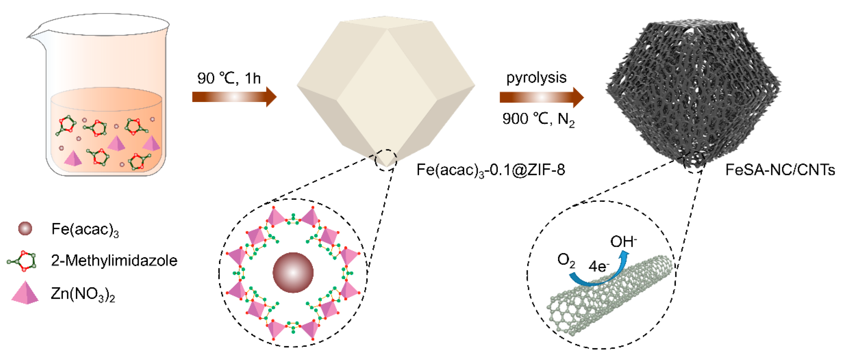
2.3. Synthesis of Fe(acac)3-0.1@ZIF-8

The synthesis process is the same as ZIF-8, with 71.6 mg (0.2 mmol) Fe(acac)3 being introduced.

2.4. Synthesis of Fe(acac)3-0.15@ZIF-8

The synthesis process was the same as ZIF-8, with 107.4 mg (0.3 mmol) Fe(acac)3 being introduced.

2.5. Synthesis of NC, FeSA-NC/CNTs and FeNP-NC/CNTs

The powders of ZIF-8 were transferred into a ceramic boat and placed in a quartz tube furnace. Then, the sample was heated to 900 °C at a heating rate of 5 °C min−1, kept at 900 °C under flowing N2 for 3 h and finally naturally cooled to room temperature. The final powders NC were collected and characterized without further treatment.
The synthesis process of FeSA-NC/CNTs was the same as NC, except that the raw material was Fe(acac)3-0.1@ZIF-8.
The synthesis process of FeNP-NC/CNTs was the same as NC, except that the raw material was Fe(acac)3-0.15@ZIF-8.

2.6. Synthesis of FeSA-NC

The powders of Fe(acac)3-0.1@ZIF-8 were transferred into a ceramic boat and placed in a quartz tube furnace. Then, the sample was heated to 800 °C at a heating rate of 5 °C min−1, kept at 800 °C under flowing N2 for 3 h, and finally naturally cooled to room temperature. The final powders of FeSA-NC were collected and characterized without further treatment.

2.7. Characterization

The morphology of the samples was characterized by scanning electron microscopy (SEM, Gemini 450, ZEISS, Jena, Germany) with an acceleration voltage of 5 kV. The transmission electron microscopy (TEM) images and element mappings were obtained at 200 kV using a JEM-2100F (JEOL, Tokyo, Japan) equipped with an X-ray energy dispersive spectrometer (EDS: X-Max 80T, Oxford, UK) for chemical composition analysis. EDS elemental maps were taken in HAADF-STEM mode. Atomic resolution analyses were performed on an aberration-corrected scanning transmission electron microscopy (AC-STEM, Grand ARM300F, JEOL, Japan) equipped with an electron energy-loss spectrometer (EELS: GIF Quantum 970, Gatan, Inc., CA, USA). The energy resolution of EELS was ∼1 eV measured at the width at half-maximum of the zero-loss peak with the energy dispersion of 0.25 eV/channel. The structures were characterized by X-ray diffraction (XRD, PANalytical Empyrean Rayon X, Eindhoven, The Netherlands) with Cu Kα radiation (λ = 1.5418 Å) at 40 kV and 40 mA with an increment of 0.04 degrees. Raman spectra were collected on a Renishaw inVia confocal Raman microscope with a 532 nm wavelength incident laser light. X-ray photoelectron spectroscopy (XPS, Kratos, AXIS Ultra DLD, Manchester, UK) was performed to investigate the chemical bond using Al K Alpha (1486.6 eV) and the value of 284.8 eV as the C 1s peak reference. A PerkinElmer Pyris Diamond was utilized for TGA measurements. The differential scanning calorimetry (DSC) was recorded on a Diamond DSC system. Nitrogen adsorption–desorption measurements were conducted on an Autosorb IQ Gas Sorption System at 77 K. The Brunauer–Emmett–Teller (BET) surface area was calculated using the adsorption data. X-ray absorption fine structure (XAFS) measurements based on Synchrotron Radiation were carried out at the 1W2B beamline at the Beijing Synchrotron Radiation Facility (BSRF), China. The EXAFS data were processed according to the standard procedures using the ATHENA module implemented in the IFEFFIT software packages (version 0.9.25, Chicago, IL, USA).

2.8. Electrochemical Measurements

A total of 2 mg of catalyst was dispersed in 1 mL Nafion (5 wt%) and sonicated for about an hour under ultrasonic treatment to form a homogeneous catalyst ink. A sample of 24.7 μL ink was dropped onto the polished glassy carbon disk electrode in order to yield a catalyst loading of 0.2 mg cm−2 and dried under an infrared lamp.
The electrochemical impedance spectroscopy (EIS) and all the electrocatalytic performance measurements were performed using a CHI 760E Electrochemical Workstation (Shanghai Chenhua, Shanghai, China). The EIS curves were obtained at the reduced peak potential with a signal amplitude of 5 mV s−1 and a frequency range of 100 kHz–100 mHz.
The oxygen reduction performance was conducted in a three-electrode system: a platinum foil as counter electrode; a saturated calomel electrode (SCE) as the reference electrode, and a glassy carbon electrode as the working electrode. All potential values were calibrated to the reversible hydrogen potential (ERHE) based on the Nernst equation:
E RHE = E SCE + 0.2415 + 0.0591 pH
O2 and N2 were saturated in 0.1 M KOH, respectively, and used as an electrolyte at room temperature. Cyclic voltammetry (CV) experiments were conducted with a sweep rate of 50 mV s−1 in the potential ranging from 0.1 to 1.2 V in O2-saturated electrolyte at a rotating disk electrode (RRDE) of 0 rpm. Then linear sweep voltammetry (LSV) experiments were carried out in the potential range from 0.1 to 1.2 V at a rotating speed ranging from 400 to 2025 rpm with a sweep rate of 5 mV s−1 at room temperature. The accelerated durability tests (ADT) of the electrocatalyst were acquired in an O2-saturated 0.1 M KOH electrolyte at room temperature, with potential cycling between 0.6 to 1 V at a sweep rate of 50 mV s−1 for 5000 cycles.
The electronic transfer number (n) was analyzed by the Koutecky–Levich (K–L) equation:
1 J = 1 J L + 1 J K = 1 B ω 1 2 + 1 J K
B = 0.62 nFC 0 D 0 2 3 V 1 6
where J represents the current density; J L and J K are the limited and kinetic current density, respectively; ω indicates the rotating rate of the electrode; n is the electron transfer number in oxygen reduction; F is the Faraday constant (96,485 C mol−1); C 0 is the bulk concentration of O2 (1.2 × 10⁻⁶ mol cm−3); D 0 is the diffusion coefficient of O2 in 0.1 M KOH (1.9 × 10⁻⁵ cm2 s−1); V is the kinematic viscosity of the electrolyte (0.01 cm2 s−1); and the constant 0.62 was used to determine B when the unit of rotating rate was rad s−1.
The H2O2 yield (H2O2%) and the electron transfer number (n) were calculated with the following equations:
H 2 O 2   ( % ) = 200 × I R N I D + I R N
n = 4 × I D I D + I R N
where I D is the disk current; I R is the ring current; and N is the ring collection efficiency with a value of 0.4.
The Tafel plot was calculated with the following equation:
η = a + b   log | J K |
where η is overpotential; J K means kinetic current density; and b indicates the Tafel plot. According to Equation (6), to make the η - log | J K | curve, take the part that fits the linear relationship, and its slope is the Tafel plot.

3. Results and Discussion

The synthesis process of Fe(acac)3-0.1@ZIF-8 and its subsequent conversion into FeSA-NC/CNTs is schematically illustrated in Figure 1. Fe(acac)3 was mixed with ZIF-8 according to the synthesis method in the previous study [23]. A molecular-scale cage was formed by Zn2+ and 2-methylimidazole with the poles and cavities being larger for one Fe(acac)3 molecule to be trapped. After pyrolysis at 900 °C under N2 flow, the final product, FeSA-NC/CNTs, was obtained after zinc evaporation at a temperature higher than 450 °C (see Figure S1 for the DSC/TGA results) [24]. The target metal (Fe) sites were spatially separated by the 2-methylimidazole bond and zinc atoms, with a greatly increasing space distance between one other. Therefore, ZIF-8 can be transformed into nitrogen-doped carbon (NC)/carbon nanotube (CNT) hybrid supports after the evaporation of zinc atoms during high temperature heat treatment in N2. A suitable amount of nitrogen dopant in carbon can effectively maintain good electrical conductivity while improving its electrocatalytic properties. Meantime, an appropriate content of Fe(acac)3 could be carbonized by the organic ligands to form isolated single iron atoms bound to the nitrogen species anchored on the carbon matrix/CNTs [25].
The morphologies of the original Fe(acac)3-0.1@ZIF-8 and as-prepared FeSA-NC/CNTs were examined by using SEM and TEM. As shown in Figure 2a and Figure S2, the original Fe(acac)3-0.1@ZIF-8 exhibited rhombic dodecahedral morphology with a particle size of about 400 nm [24]. After pyrolysis at 900 °C under N2 for 3 h, the sample still maintained its previous rhombic dodecahedral morphology with many thread-like or filamentous substances decorated on the surface of the particles (Figure 2b). The TEM and HRTEM images in Figure 2c,d show that these crisscross substances were thin-walled carbon nanotubes with a diameter of around 10 nm. No obvious nanoparticles (NPs) were observed on these carbon nanotubes or the rhombododecahedral carbon matrix, implying the possible formation of Fe single atoms. Corresponding STEM-EDS elemental maps in Figure 2e–h demonstrate that the signals of Fe, N, and C were uniformly dispersed on the NC and CNTs.
Furthermore, AC-HAADF-STEM was used to visualize the microstructure of NC and CNTs at the atomic scale. Due to the much higher atomic number (Z) of the Fe atoms compared to that of C and N atoms [26], bright dots representing Fe single atoms distributed on NC as well as CNTs can be observed in HAADF images (highlighted by red circles in Figure 2i–j and Figure S3). Moreover, EELS spectra taken at the carbon matrix and carbon nanotubes (Figure 2k) indicated the co-existence of Fe, N, and C, demonstrating the formation of abundant Fe–N4 moieties. As known, for SACs, if metallic catalysts are not completely encapsulated or simply anchored on the surface of the carbon-based support, they are not effective at preventing the leaching of metallic ion under harsh operating conditions. In addition, fully encapsulating the metal catalysts into a thicker carbon matrix, but away from the surface, may hinder the effective electron transfer between the catalysts and the reactants [27]. In our work, the NC/CNT hybrid supports possessed much higher surface area (1626.814 m2 g−1) thanks to their mesoporous structure (Figure S4), which is not only beneficial to the full utilization of Fe–N4 active sites [28], but may also facilitate oxygen mass transfer within the catalyst film. Therefore, our FeSA-NC/CNTs catalyst exhibited a high electrocatalytic activity and stability in ORR [19]. These aspects demonstrate the advantages of manufacturing well-dispersed Fe–N–C catalysts by using MOFs as a template.
To further explore the formation mechanism of FeSA-NC/CNTs, MOF precursors with different contents of Fe(acac)3 were synthesized. It was found that after pyrolysis at the same conditions, FeNP-NC/CNTs with obvious Fe NPs could be observed at the end of the formed CNTs (Figure S5) when the content of Fe(acac)3 in ZIF-8 was changed from 0.1 to 0.15. Moreover, when the pyrolysis temperature was reduced to 800 °C, only Fe single atoms (SAs) anchored on NC were formed while neither Fe NPs nor CNTs were formed (Figure S6). Based on the above results, it is speculated that the formation of Fe SAs on both NC and CNTs can be attributed to delicately tuning the content of Fe(acac)3 in ZIF-8 and pyrolysis temperature. The content of doped Fe(acac)3 should be controlled, as the ORR performance is far from being ideal if the amount is small (less active sites are involved) and clusters or eventually nanoparticles will be formed if the amount is too large [29,30]. Besides, higher pyrolysis temperature will be critical for improving the graphitization of carbon to form a porous carbon matrix as well as CNTs with the existence of Fe.
XRD, Raman, and XPS were employed to further investigate the structural properties and chemical composition of the electrocatalysts. The XRD patterns of original ZIF-8 and Fe(acac)3-0.1@ZIF-8 powders (Figure 3a) showed almost identical diffraction peaks, indicating that the addition of Fe(acac)3 does not change the structure of ZIF-8 [31,32]. Similar to the XRD pattern of NC derived from pure ZIF-8 (the blue line in Figure 3a), there was a much broader diffraction peak in the range of 20–30° (indexed to (002) planes of graphitic carbon) for that of FeSA-NC/CNTs (the green line in Figure 3a), demonstrating the formation of a graphitic carbon structure [33], whereas the degree of graphitization was not good enough. Furthermore, no diffraction peak corresponding to the bulk-centered cubic α-Fe (PDF#87-0722) was detected in Figure 3a, which proves that there was no formation of any iron nanoparticles in FeSA-NC/CNTs. In contrast, the XRD pattern of FeNP-NC/CNTs (Figure S7) showed a small but distinct diffraction peak at about 44°, which verified the presence of Fe NPs. As seen in the Raman spectra shown in Figure 3b, the peaks of the D-band and G-band for both the NC and FeSA-NC/CNTs were roughly at 1354 cm−1 and 1591 cm−1, respectively. It is well-known that the ratio of the integrated area of the D-band to the G-band is related to the defect density in the lattice [33]. The decrease in this ratio from NC to FeSA-NC/CNTs implies that the doping of iron drives an increase in the graphitization of ZIF-8-derived carbon hybrid supports, in line with the XRD results, which may improve the electrical conductivity of the carbon supports and promote electron transfer for electrochemical applications [34]. The XPS spectra of FeSA-NC/CNTs (Figure 3c) showed four peaks for C 1s, N 1s, O 1s, and Fe 2p, confirming the presence of carbon, nitrogen, oxygen, and especially iron, which is present in a small but real amount. It should be noted that the O 1s peak may come from surface adsorbed oxygen in the environment. The C 1s peak (Figure S8a) can be deconvoluted into three peaks centered at 284.8, 286.0, and 290.0 eV, which can be attributed to the C–C, C–N, and C=O bonds, respectively [35]. The XPS spectrum of Fe 2p showed two spin-orbit doublets at 711.7 and 722.9 eV, which can be attributed to the Fe 2p3/2 and Fe 2p1/2 orbits. Unfortunately, the Fe signal was not very visible, perhaps related to the coverage of carbon matrix/carbon nanotubes and/or the iron content below the detection limit (Figure S8b). The presence of C–N bonds indicates the successful nitrogen doping in the carbon matrix. In addition, high-resolution N 1s spectra showed the presence of porphyrin-like Fe–N4 moieties at 399.7 eV as well as pyridinic (398.5 eV), pyrrolic (400.9 eV), graphitic (403.5 eV), and N–Ox (406.3 eV) (Figure 3d) [36]. According to previous studies, pyridinic N and pyrrolic N can provide coordination sites by moving lone pairs to the carbon plane, which can enhance the chemisorption of oxygen molecules and intermediates during the ORR process [37,38]. Graphitic N not only improves the conductivity of the catalyst, but also the presence of C–N bonds can induce an inhomogeneous distribution of electrons, thus promoting the adsorption of O2 and the dissociation or weakening of O=O bonds [39,40,41].
To further investigate the chemical state and coordination environment of the Fe sites in FeSA-NC/CNTs, X-ray absorption near-edge structure (XANES) and extended X-ray absorption fine structure (EXAFS) were carried out at the Fe K-edge. Fe foil, FePc, and Fe2O3 samples were also measured as reference samples. As illustrated in the Fe K-edge XANES spectra of FeSA-NC/CNTs (Figure 4a), the adsorption edge was located between Fe foil and Fe2O3, indicating that the oxidation state of the Fe species was between Fe0 and Fe3+, and close to Fe2+. The EXAFS spectra of FeSA-NC/CNTs (Figure 4b) showed a prominent peak centered at 1.5 Å, which was mainly attributed to the first Fe–N coordination shell [42,43]. Moreover, compared to the Fe foil, the absence of scattering peaks derived from Fe–Fe coordination in FeSA-NC/CNTs suggests that Fe species were monodispersed in the N-doped carbon matrix/CNT hybrid supports [44]. The coordination structure of the Fe atoms in the FeSA-NC/CNTs was further investigated by quantitative EXAFS curve fitting analyses (Figure 4c and Table S1), which clearly revealed that the Fe center was coordinated with four N atoms at the first coordination shell. All fitting results were well consistent with the experimental data, from which the average coordination numbers of Fe–N was obtained as 4.2, with the average bond lengths for Fe–N of 2.01 Å, respectively (see more details in Table S2). Furthermore, the wavelet transform (WT, Figure 4d–f) results displayed only one WT intensity maximum at ≈3.8 Å−1, associated with the Fe–N pair. Compared with the WT plots of Fe foil, the WT signal related to Fe–Fe contribution was not detected in the FeSA-NC/CNTs. These observations further demonstrate that the single Fe atoms simultaneously coordinated with N atoms, forming the Fe–N bonds.
The construction of the FeSA-NC/CNTs catalyst was dedicated to improving the ORR catalytic performance, which was investigated by cyclic voltammetry (CV, Figure S9) and linear scanning voltammetry (LSV) in an O2-saturated 0.1 M KOH solution based on a three-electrode system under rotating disk electrode (RDE). A commercial 20 wt% Pt/C catalyst (20 wt% metal, Alfa Aesar) was used as the reference for the performance comparison. All given potentials refer to the reversible hydrogen electrode (RHE). This ORR performance was compared in this work to other similar published research (Table S3). FeSA-NC/CNTs showed a reduction peak at 0.82 V, indicating a certain ORR activity (Figure S9). As shown in Figure 5a, the onset potential (Eonset) with a value of about 0.93 V for FeSA-NC/CNTs was slightly inferior to that of Pt/C, but much better than that of FeNP-NC/CNTs and FeSA-NC. It demonstrates that the high-performance Fe-SAC catalyst can be prepared by tuning the content of Fe(acac)3 in ZIF-8 and the pyrolytic conditions. According to Figure 5b, FeSA-NC/CNTs deliver a higher half-wave potential (E1/2 = 0.86 V) than that of Pt/C (0.846 V). The kinetic current density (Jk) of FeSA-NC/CNTs (39.3 mA cm−2) at 0.8 V was also much higher than that of Pt/C (14.4 mA cm−2), indicating its superior kinetics. To further unveil the electron transfer mechanism of FeSA-NC/CNTs, the LSV curves at different rotating rates are depicted in Figure 5c. The Koutecky–Levich (K–L) curves obtained from the LSV curves exhibited good linearity, showing the primary reaction kinetics related to the O2 concentration and the potential-independent electron transfer rate (Figure 5c, inset) [45]. The yield of H2O2 and electron transfer number were confirmed by the rotating ring-disk electrode (RRDE), suggesting a superior selectivity of oxygen reduction for H2O with an electron transfer number greater than 3.9 and a H2O2 yield below 5% over the potential range of 0.2 to 0.9 V (Figure 5d) [46]. The Tafel slope of FeSA-NC/CNTs was about 74.4 mV dec−1, which was significantly lower than that of Pt/C (104.6 mV dec−1), demonstrating the FeSA-NC/CNTs electrocatalyst possessed accelerated ORR kinetics (Figure 5e) [47]. It should be noted that there was no significant decay of E1/2 (ca. 1 mV) after 5000 consecutive potential cycles (Figure 5f), which proves that the FeSA-NC/CNT catalyst also has superb durability.
The electrochemical impedance spectroscopy (EIS) was also measured (Figure S10). The Nyquist plots were fitted by an equivalent circuit model. As shown in Figure S10a–c, FeSA-NC/CNTs showed the smallest arc radius (Rct: 100.3 Ω) in the Nyquist plot compared with FeNP-NC/CNTs and FeSA-NC, indicating the lowest charge-transfer resistance at the catalyst/electrolyte interface and superior charge transport kinetics [48]. The Bode plots can be used to estimate the effectiveness of ion diffusion. The ion diffusion in the low-frequency region is related to the phase angle. The smaller the phase angle, the faster the ion diffusion [49]. Therefore, FeNP-NC/CNTs have a more favorable diffusion angle (<−40°). The phase angle of FeSA-NC/CNTs and FeSA-NC was close to 0° in the low-frequency region, demonstrating that diffusion was not the dominant mechanism. At lower frequencies, the impedance (|Z|) was much higher due to mass transfer effects, while at higher frequencies, the lower the impedance, the easier the charge transfer. FeSA-NC/CNTs had the lowest impedance at high frequencies (65 Ω), implying that charge transfer dominates. It can be seen that the value of |Z| decreased the most in FeNP-NC/CNTs, implying the breaking of the activation barrier and promoting charge transfer in the high-frequency region and charge diffusion in the low-frequency region.

4. Conclusions

In summary, we synthesized a single-atom FeSA-NC/CNTs catalyst through the cage-encapsulated-precursor pyrolysis strategy by skillfully tuning the pyrolyzed temperature and the content of Fe(acac)3 in the precursors. Based on the results of HRTEM, EDS, and HAADF-STEM, it is clear that the catalyst has a large number of Fe single atoms distributed on the NC/CNT hybrid supports as a mesoporous structure with a specific surface area of 1626.814 m2 g−1. Benefiting from the high density and superb accessibility of Fe–N4 active sites, the catalyst exhibited excellent ORR performance with a half-wave potential (E1/2) of 0.86 V, which exceeded that of commercial Pt/C. It had a high kinetic current density (Jk) of 39.3 mV cm−2 at 0.8 V. The yield of H2O2 was below 5% and the electron transfer number was close to 4, indicating that FeSA-NC/CNTs had a high electrocatalytic efficiency. Besides, it showed excellent stability with little change in the ORR polarization curve after 5000 CV cycles. In short, the outstanding catalytic activity of FeSA-NC/CNTs can be attributed to the synergistic roles of abundant Fe single atoms as well as the porous NC/CNT hybrid architectures, which ensures the full utilization of Fe–N4 active sites with improved electron transfer and oxygen mass transport.

Supplementary Materials

The following supporting information can be downloaded at: https://www.mdpi.com/article/10.3390/nano12091593/s1, Figure S1: (a) TGA and (b) DSC curves of Fe(acac)3-0.1@ZIF-8. The weight loss was attributed to the decomposition of ZIF-8 and the release of Zn species. That is, the Zn nodes with a low boiling point of 907 °C would evaporate at such high temperatures, leaving the N rich defects; Figure S2: TEM image of Fe(acac)3-0.1@ZIF-8; Figure S3: (a) and (b) are representative HAADF-STEM images of FeSA-NC/CNTs at different areas; Figure S4: (a) N2 sorption isotherms of FeSA-NC/CNTs. (b) Corresponding pore size distribution curve calculated using the DFT methods; Figure S5: (a) TEM and (b) HAADF-STEM images of FeNP-NC/CNTs, where typical iron single atoms are marked by red circles; Figure S6: (a) TEM and (b) HAADF-STEM images of FeSA-NC, where typical iron single atoms are marked by red circles; Figure S7: XRD patterns of FeSA-NC/CNTs and FeNP-NC/CNTs; Figure S8: (a) High resolution XPS C 1s spectra of FeSA-NC/CNTs. (b) High resolution XPS Fe 2p spectra of FeSA-NC/CNTs.; Figure S9: CV curves of FeSA-NC/CNTs in O2-saturated 0.1 M KOH with a sweep rate of 50 mV/s; Figure S10: Nyquist plots of (a) FeSA-NC/CNTs, (b) FeSA-NC, and (c) FeNP-NC/CNTs, where the inset is the equivalent circuit model for impedance spectra fitting. Bode plots of (d) FeSA-NC/CNTs, (e) FeSA-NC, and (f) FeNP-NC/CNTs. Table S1: Fitting results of Fe foil EXAFS; Table S2: Fitting results of sample–Fe EXAFS; Table S3: Comparison of ORR performance with some reported non-precious catalysts in 0.1 M KOH. References [14,50,51,52,53,54,55,56,57,58,59,60,61,62,63,64,65,66] are cited in the supplementary materials.

Author Contributions

Conceptualization, Y.J., M.H., R.H., and R.Q.; Methodology, Y.J., W.Z. and M.H.; Formal analysis, Y.J. and W.X.; Investigation, Y.J. and C.S.; Software, Y.J.; Data curation, Y.J.; Writing—original draft preparation, Y.J.; Funding acquisition, R.H.; Supervision, R.Q.; Writing—review and editing, R.H. and R.Q. All authors have read and agreed to the published version of the manuscript.

Funding

This work was supported by the National Key Research and Development Program of China (2017YFA0303403), the Shanghai Science and Technology Innovation Action Plan (No. 19JC1416700), and the National Natural Science Foundation of China (Grant Nos. 61974042 and 11774092).

Institutional Review Board Statement

Not applicable.

Informed Consent Statement

Not applicable.

Data Availability Statement

The data presented in this study are available on request from the corresponding author.

Conflicts of Interest

The authors declare no conflict of interest.

References

  1. Holby, E.F.; Wang, G.; Zelenay, P. Acid stability and demetalation of PGM-free ORR electrocatalyst structures from density functional theory: A model for “single-atom catalyst” dissolution. ACS Catal. 2020, 10, 14527–14539. [Google Scholar] [CrossRef]
  2. Wang, K.; Du, L.; Wei, Q.; Zhang, J.; Zhang, G.; Xing, W.; Sun, S. A Lactate/Oxygen Biofuel Cell: The Coupled Lactate Oxidase Anode and PGM-Free Fe-N-C Cathode. ACS Appl. Mater. Interfaces 2019, 11, 42744–42750. [Google Scholar] [CrossRef] [PubMed]
  3. Jia, Y.; Jiang, K.; Wang, H.; Yao, X. The role of defect sites in nanomaterials for electrocatalytic energy conversion. Chem 2019, 5, 1371–1397. [Google Scholar] [CrossRef]
  4. Cao, H.; Xia, G.-J.; Chen, J.-W.; Yan, H.-M.; Huang, Z.; Wang, Y.-G. Mechanistic insight into the oxygen reduction reaction on the Mn-N4/C single-atom catalyst: The role of the solvent environment. J. Phys. Chem. C 2020, 124, 7287–7294. [Google Scholar] [CrossRef]
  5. He, Y.; Guo, H.; Hwang, S.; Yang, X.; He, Z.; Braaten, J.; Karakalos, S.; Shan, W.; Wang, M.; Zhou, H. Single cobalt sites dispersed in hierarchically porous nanofiber networks for durable and high-power PGM-free cathodes in fuel cells. Adv. Mater. 2020, 32, 2003577. [Google Scholar] [CrossRef]
  6. Fei, H.; Dong, J.; Feng, Y.; Allen, C.S.; Wan, C.; Volosskiy, B.; Li, M.; Zhao, Z.; Wang, Y.; Sun, H. General synthesis and definitive structural identification of MN4C4 single-atom catalysts with tunable electrocatalytic activities. Nat. Catal. 2018, 1, 63–72. [Google Scholar] [CrossRef]
  7. Hou, C.C.; Zou, L.; Sun, L.; Zhang, K.; Liu, Z.; Li, Y.; Li, C.; Zou, R.; Yu, J.; Xu, Q. Single-atom iron catalysts on overhang-eave carbon cages for high-performance oxygen reduction reaction. Angew. Chem. 2020, 132, 7454–7459. [Google Scholar] [CrossRef]
  8. Liu, J.; Jiao, M.; Lu, L.; Barkholtz, H.M.; Li, Y.; Wang, Y.; Jiang, L.; Wu, Z.; Liu, D.-J.; Zhuang, L. High performance platinum single atom electrocatalyst for oxygen reduction reaction. Nat. Commun. 2017, 8, 15938. [Google Scholar] [CrossRef] [Green Version]
  9. Zitolo, A.; Goellner, V.; Armel, V.; Sougrati, M.-T.; Mineva, T.; Stievano, L.; Fonda, E.; Jaouen, F. Identification of catalytic sites for oxygen reduction in iron-and nitrogen-doped graphene materials. Nat. Mater. 2015, 14, 937–942. [Google Scholar] [CrossRef]
  10. Wan, X.; Liu, X.; Li, Y.; Yu, R.; Zheng, L.; Yan, W.; Wang, H.; Xu, M.; Shui, J. Fe-N-C electrocatalyst with dense active sites and efficient mass transport for high-performance proton exchange membrane fuel cells. Nat. Catal. 2019, 2, 259–268. [Google Scholar] [CrossRef]
  11. Shao, Y.; Dodelet, J.P.; Wu, G.; Zelenay, P. PGM-free cathode catalysts for PEM fuel cells: A mini-review on stability challenges. Adv. Mater. 2019, 31, 1807615. [Google Scholar] [CrossRef] [PubMed]
  12. Lü, F.; Zhao, S.; Guo, R.; He, J.; Peng, X.; Bao, H.; Fu, J.; Han, L.; Qi, G.; Luo, J. Nitrogen-coordinated single Fe sites for efficient electrocatalytic N2 fixation in neutral media. Nano Energy 2019, 61, 420–427. [Google Scholar] [CrossRef]
  13. Dou, S.; Wang, X.; Wang, S. Rational design of transition metal-based materials for highly efficient electrocatalysis. Small Methods 2019, 3, 1800211. [Google Scholar] [CrossRef] [Green Version]
  14. Han, J.; Meng, X.; Lu, L.; Bian, J.; Li, Z.; Sun, C. Single-atom Fe-Nx-C as an efficient electrocatalyst for zinc–air batteries. Adv. Funct. Mater. 2019, 29, 1808872. [Google Scholar] [CrossRef]
  15. Wu, X.-T.; Peng, L.-J.; Xiao, K.; Li, N.; Liu, Z.-Q. Rational design and synthesis of hollow Fe-N/C electrocatalysts for enhanced oxygen reduction reaction. Chem. Commun. 2021, 57, 5258–5261. [Google Scholar] [CrossRef] [PubMed]
  16. Zhang, H.; Chung, H.T.; Cullen, D.A.; Wagner, S.; Kramm, U.I.; More, K.L.; Zelenay, P.; Wu, G. High-performance fuel cell cathodes exclusively containing atomically dispersed iron active sites. Energy Environ. Sci. 2019, 12, 2548–2558. [Google Scholar] [CrossRef]
  17. Jin, H.; Zhou, H.; He, D.; Wang, Z.; Wu, Q.; Liang, Q.; Liu, S.; Mu, S. MOF-derived 3D Fe-NS co-doped carbon matrix/nanotube nanocomposites with advanced oxygen reduction activity and stability in both acidic and alkaline media. Appl. Catal. B Environ. 2019, 250, 143–149. [Google Scholar] [CrossRef]
  18. Meng, J.; Niu, C.; Xu, L.; Li, J.; Liu, X.; Wang, X.; Wu, Y.; Xu, X.; Chen, W.; Li, Q. General oriented formation of carbon nanotubes from metal–organic frameworks. J. Am. Chem. Soc. 2017, 139, 8212–8221. [Google Scholar] [CrossRef]
  19. Tavakkoli, M.; Flahaut, E.; Peljo, P.; Sainio, J.; Davodi, F.; Lobiak, E.V.; Mustonen, K.; Kauppinen, E.I. Mesoporous single-atom-doped graphene–carbon nanotube hybrid: Synthesis and tunable electrocatalytic activity for oxygen evolution and reduction reactions. ACS Catal. 2020, 10, 4647–4658. [Google Scholar] [CrossRef] [Green Version]
  20. Kone, I.; Ahmad, Z.; Xie, A.; Tang, Y.; Sun, Y.; Chen, Y.; Yang, X.; Wan, P. In Situ Growth of Co4N Nanoparticles-Embedded Nitrogen-Doped Carbon Nanotubes on Metal-Organic Framework-Derived Carbon Composite as Highly Efficient Electrocatalyst for Oxygen Reduction and Evolution Reactions. Energy Technol. 2020, 8, 2000409. [Google Scholar] [CrossRef]
  21. Xie, Y.; Feng, C.; Guo, Y.; Li, S.; Guo, C.; Zhang, Y.; Wang, J. MOFs derived carbon nanotubes coated CoNi alloy nanocomposites with N-doped rich-defect and abundant cavity structure as efficient trifunctional electrocatalyst. Appl. Surf. Sci. 2021, 536, 147786. [Google Scholar] [CrossRef]
  22. Xia, B.Y.; Yan, Y.; Li, N.; Wu, H.B.; Lou, X.W.D.; Wang, X. A metal-organic framework-derived bifunctional oxygen electrocatalyst. Nat. Energy 2016, 1, 15006. [Google Scholar] [CrossRef]
  23. Chen, Y.; Ji, S.; Wang, Y.; Dong, J.; Chen, W.; Li, Z.; Shen, R.; Zheng, L.; Zhuang, Z.; Wang, D. Isolated single iron atoms anchored on N-doped porous carbon as an efficient electrocatalyst for the oxygen reduction reaction. Angew. Chem. 2017, 129, 7041–7045. [Google Scholar] [CrossRef]
  24. Schejn, A.; Balan, L.; Falk, V.; Aranda, L.; Medjahdi, G.; Schneider, R. Controlling ZIF-8 nano-and microcrystal formation and reactivity through zinc salt variations. CrystEngComm 2014, 16, 4493–4500. [Google Scholar] [CrossRef]
  25. Han, A.; Wang, B.; Kumar, A.; Qin, Y.; Jin, J.; Wang, X.; Yang, C.; Dong, B.; Jia, Y.; Liu, J. Recent advances for MOF-derived carbon-supported single-atom catalysts. Small Methods 2019, 3, 1800471. [Google Scholar] [CrossRef]
  26. Nellist, P.; Pennycook, S. Subangstrom resolution by underfocused incoherent transmission electron microscopy. Phys. Rev. Lett. 1998, 81, 4156. [Google Scholar] [CrossRef]
  27. Xu, Y.; Tu, W.; Zhang, B.; Yin, S.; Huang, Y.; Kraft, M.; Xu, R. Nickel nanoparticles encapsulated in few-layer nitrogen-doped graphene derived from metal–organic frameworks as efficient bifunctional electrocatalysts for overall water splitting. Adv. Mater. 2017, 29, 1605957. [Google Scholar] [CrossRef]
  28. Jiao, L.; Li, J.; Richard, L.L.; Sun, Q.; Stracensky, T.; Liu, E.; Sougrati, M.T.; Zhao, Z.; Yang, F.; Zhong, S. Chemical vapour deposition of Fe-N-C oxygen reduction catalysts with full utilization of dense Fe-N4 sites. Nat. Mater. 2021, 20, 1385–1391. [Google Scholar] [CrossRef]
  29. Han, A.; Chen, W.; Zhang, S.; Zhang, M.; Han, Y.; Zhang, J.; Ji, S.; Zheng, L.; Wang, Y.; Gu, L. A polymer encapsulation strategy to synthesize porous nitrogen-doped carbon-nanosphere-supported metal isolated-single-atomic-site catalysts. Adv. Mater. 2018, 30, 1706508. [Google Scholar] [CrossRef]
  30. Shang, H.; Wang, T.; Pei, J.; Jiang, Z.; Zhou, D.; Wang, Y.; Li, H.; Dong, J.; Zhuang, Z.; Chen, W. Design of a Single-Atom Indiumδ+-N4 Interface for Efficient Electroreduction of CO2 to Formate. Angew. Chem. Int. Ed. 2020, 59, 22465–22469. [Google Scholar] [CrossRef]
  31. Mamtani, K.; Jain, D.; Dogu, D.; Gustin, V.; Gunduz, S.; Co, A.C.; Ozkan, U.S. Insights into oxygen reduction reaction (ORR) and oxygen evolution reaction (OER) active sites for nitrogen-doped carbon nanostructures (CNx) in acidic media. Appl. Catal. B Environ. 2018, 220, 88–97. [Google Scholar] [CrossRef]
  32. Zhong, H.x.; Wang, J.; Zhang, Y.w.; Xu, W.l.; Xing, W.; Xu, D.; Zhang, Y.F.; Zhang, X.B. ZIF-8 derived graphene-based nitrogen-doped porous carbon sheets as highly efficient and durable oxygen reduction electrocatalysts. Angew. Chem. Int. Ed. 2014, 53, 14235–14239. [Google Scholar] [CrossRef]
  33. Tuinstra, F.; Koenig, J.L. Raman spectrum of graphite. J. Chem. Phys. 1970, 53, 1126–1130. [Google Scholar] [CrossRef] [Green Version]
  34. Hou, C.C.; Zou, L.; Xu, Q. A hydrangea-like superstructure of open carbon cages with hierarchical porosity and highly active metal sites. Adv. Mater. 2019, 31, 1904689. [Google Scholar] [CrossRef] [PubMed]
  35. Artyushkova, K.; Kiefer, B.; Halevi, B.; Knop-Gericke, A.; Schlogl, R.; Atanassov, P. Density functional theory calculations of XPS binding energy shift for nitrogen-containing graphene-like structures. Chem. Commun. 2013, 49, 2539–2541. [Google Scholar] [CrossRef] [PubMed] [Green Version]
  36. Ju, W.; Bagger, A.; Hao, G.-P.; Varela, A.S.; Sinev, I.; Bon, V.; Roldan Cuenya, B.; Kaskel, S.; Rossmeisl, J.; Strasser, P. Understanding activity and selectivity of metal-nitrogen-doped carbon catalysts for electrochemical reduction of CO2. Nat. Commun. 2017, 8, 944. [Google Scholar] [CrossRef]
  37. Lai, L.; Potts, J.R.; Zhan, D.; Wang, L.; Poh, C.K.; Tang, C.; Gong, H.; Shen, Z.; Lin, J.; Ruoff, R.S. Exploration of the active center structure of nitrogen-doped graphene-based catalysts for oxygen reduction reaction. Energy Environ. Sci. 2012, 5, 7936–7942. [Google Scholar] [CrossRef]
  38. Lai, Q.; Zhao, Y.; Liang, Y.; He, J.; Chen, J. In situ confinement pyrolysis transformation of ZIF-8 to nitrogen-enriched meso-microporous carbon frameworks for oxygen reduction. Adv. Funct. Mater. 2016, 26, 8334–8344. [Google Scholar] [CrossRef]
  39. Li, H.; Du, K.; Xiang, C.; An, P.; Shu, X.; Dang, Y.; Wu, C.; Wang, J.; Du, W.; Zhang, J. Controlled chelation between tannic acid and Fe precursors to obtain N, S co-doped carbon with high density Fe-single atom-nanoclusters for highly efficient oxygen reduction reaction in Zn-air batteries. J. Mater. Chem. A 2020, 8, 17136–17149. [Google Scholar] [CrossRef]
  40. Wu, M.; Wang, K.; Yi, M.; Tong, Y.; Wang, Y.; Song, S. A facile activation strategy for an MOF-derived metal-free oxygen reduction reaction catalyst: Direct access to optimized pore structure and nitrogen species. Acs Catal. 2017, 7, 6082–6088. [Google Scholar] [CrossRef]
  41. Yan, Y.; Cheng, H.; Qu, Z.; Yu, R.; Liu, F.; Ma, Q.; Zhao, S.; Hu, H.; Cheng, Y.; Yang, C. Recent Progress in Synthesis and Oxygen Reduction Applications of Fe-based Single-Atom and Double-Atom Catalysts. J. Mater. Chem. A 2021, 9, 19489–19507. [Google Scholar] [CrossRef]
  42. Jiang, R.; Li, L.; Sheng, T.; Hu, G.; Chen, Y.; Wang, L. Edge-site engineering of atomically dispersed Fe-N4 by selective C-N bond cleavage for enhanced oxygen reduction reaction activities. J. Am. Chem. Soc. 2018, 140, 11594–11598. [Google Scholar] [CrossRef] [PubMed]
  43. Liu, Q.; Liu, X.; Zheng, L.; Shui, J. The solid-phase synthesis of an Fe-N-C electrocatalyst for high-power proton-exchange membrane fuel cells. Angew. Chem. 2018, 130, 1218–1222. [Google Scholar] [CrossRef]
  44. Wang, X.; Jia, Y.; Mao, X.; Liu, D.; He, W.; Li, J.; Liu, J.; Yan, X.; Chen, J.; Song, L. Edge-Rich Fe-N4 Active Sites in Defective Carbon for Oxygen Reduction Catalysis. Adv. Mater. 2020, 32, 2000966. [Google Scholar] [CrossRef] [PubMed]
  45. Yin, P.; Yao, T.; Wu, Y.; Zheng, L.; Lin, Y.; Liu, W.; Ju, H.; Zhu, J.; Hong, X.; Deng, Z. Single cobalt atoms with precise N-coordination as superior oxygen reduction reaction catalysts. Angew. Chem. 2016, 128, 10958–10963. [Google Scholar] [CrossRef]
  46. Zhang, L.; Fischer, J.M.T.A.; Jia, Y.; Yan, X.; Xu, W.; Wang, X.; Chen, J.; Yang, D.; Liu, H.; Zhuang, L. Coordination of atomic Co-Pt coupling species at carbon defects as active sites for oxygen reduction reaction. J. Am. Chem. Soc. 2018, 140, 10757–10763. [Google Scholar] [CrossRef] [Green Version]
  47. Chong, L.; Wen, J.; Kubal, J.; Sen, F.G.; Zou, J.; Greeley, J.; Chan, M.; Barkholtz, H.; Ding, W.; Liu, D.-J. Ultralow-loading platinum-cobalt fuel cell catalysts derived from imidazolate frameworks. Science 2018, 362, 1276–1281. [Google Scholar] [CrossRef]
  48. Li, Y.; Zhou, W.; Dong, J.; Luo, Y.; An, P.; Liu, J.; Wu, X.; Xu, G.; Zhang, H.; Zhang, J. Interface engineered in situ anchoring of Co9S8 nanoparticles into a multiple doped carbon matrix: Highly efficient zinc–air batteries. Nanoscale 2018, 10, 2649–2657. [Google Scholar] [CrossRef]
  49. Wang, J.; Cui, C.; Gao, G.; Zhou, X.; Wu, J.; Yang, H.; Li, Q.; Wu, G. A new method to prepare vanadium oxide nano-urchins as a cathode for lithium ion batteries. RSC Adv. 2015, 5, 47522–47528. [Google Scholar] [CrossRef]
  50. Chen, G.; Liu, P.; Liao, Z.; Sun, F.; He, Y.; Zhong, H.; Zhang, T.; Zschech, E.; Chen, M.; Wu, G. Zinc-mediated template synthesis of Fe-N-C electrocatalysts with densely accessible Fe-Nx active sites for efficient oxygen reduction. Adv. Mater. 2020, 32, 1907399. [Google Scholar] [CrossRef] [Green Version]
  51. Ge, X.; Su, G.; Che, W.; Yang, J.; Zhou, X.; Wang, Z.; Qu, Y.; Yao, T.; Liu, W.; Wu, Y. Atomic filtration by graphene oxide membranes to access atomically dispersed single atom catalysts. ACS Catal. 2020, 10, 10468–10475. [Google Scholar] [CrossRef]
  52. Xiao, M.; Xing, Z.; Jin, Z.; Liu, C.; Ge, J.; Zhu, J.; Wang, Y.; Zhao, X.; Chen, Z. Preferentially engineering FeN4 edge sites onto graphitic nanosheets for highly active and durable oxygen electrocatalysis in rechargeable Zn–air batteries. Adv. Mater. 2020, 32, 2004900. [Google Scholar] [CrossRef] [PubMed]
  53. Xie, X.; Peng, L.; Yang, H.; Waterhouse, G.I.; Shang, L.; Zhang, T. MIL-101-Derived Mesoporous Carbon Supporting Highly Exposed Fe Single-Atom Sites as Efficient Oxygen Reduction Reaction Catalysts. Adv. Mater. 2021, 33, 2101038. [Google Scholar] [CrossRef] [PubMed]
  54. Wang, X.; Zhu, H.; Yang, C.; Lu, J.; Zheng, L.; Liang, H.-P. Mesoporous carbon promoting the efficiency and stability of single atomic electrocatalysts for oxygen reduction reaction. Carbon 2022, 191, 393–402. [Google Scholar] [CrossRef]
  55. Liu, X.; Zhai, X.; Sheng, W.; Tu, J.; Zhao, Z.; Shi, Y.; Xu, C.; Ge, G.; Jia, X. Isolated single iron atoms anchored on a N, S-codoped hierarchically ordered porous carbon framework for highly efficient oxygen reduction. J. Mater. Chem. A 2021, 9, 10110–10119. [Google Scholar] [CrossRef]
  56. Wang, X.; Yang, C.; Wang, X.; Zhu, H.; Cao, L.; Chen, A.; Gu, L.; Zhang, Q.; Zheng, L.; Liang, H.-P. Green Synthesis of a Highly Efficient and Stable Single-Atom Iron Catalyst Anchored on Nitrogen-Doped Carbon Nanorods for the Oxygen Reduction Reaction. ACS Sustain. Chem. Eng. 2020, 9, 137–146. [Google Scholar] [CrossRef]
  57. Wei, S.; Wang, Y.; Chen, W.; Li, Z.; Cheong, W.-C.; Zhang, Q.; Gong, Y.; Gu, L.; Chen, C.; Wang, D. Atomically dispersed Fe atoms anchored on COF-derived N-doped carbon nanospheres as efficient multi-functional catalysts. Chem. Sci. 2020, 11, 786–790. [Google Scholar] [CrossRef] [Green Version]
  58. Han, J.; Bao, H.; Wang, J.-Q.; Zheng, L.; Sun, S.; Wang, Z.L.; Sun, C. 3D N-doped ordered mesoporous carbon supported single-atom Fe-NC catalysts with superior performance for oxygen reduction reaction and zinc-air battery. Appl. Catal. B Environ. 2021, 280, 119411. [Google Scholar] [CrossRef]
  59. Wang, Z.; Shang, N.; Wang, W.; Gao, S.; Zhang, S.; Gao, W.; Cheng, X.; Wang, C. Atomically dispersed Co anchored on S, N-riched carbon for efficient oxygen reduction and Zn-air battery. J. Alloy. Compd. 2022, 899, 163225. [Google Scholar] [CrossRef]
  60. Rao, P.; Luo, J.; Wu, D.; Li, J.; Chen, Q.; Deng, P.; Shen, Y.; Tian, X. Isolated Co Atoms Anchored on Defective Nitrogen-doped Carbon Graphene as Efficient Oxygen Reduction Reaction Electrocatalysts. Energy Environ. Mater. 2022. [Google Scholar] [CrossRef]
  61. Sun, T.; Zang, W.; Yan, H.; Li, J.; Zhang, Z.; Bu, Y.; Chen, W.; Wang, J.; Lu, J.; Su, C. Engineering the coordination environment of single cobalt atoms for efficient oxygen reduction and hydrogen evolution reactions. ACS Catal. 2021, 11, 4498–4509. [Google Scholar] [CrossRef]
  62. Wu, H.; Wu, J.; Li, Y.; Li, W.; Zhai, J.; Jiang, Q.; Xu, X.; Gao, Y. Enhanced oxygen reduction with carbon-polyhedron-supported discrete cobalt-nitrogen sites for Zn-air batteries. Chem. Eng. J. 2022, 431, 134084. [Google Scholar] [CrossRef]
  63. Guo, Y.; Liu, F.; Feng, L.; Wang, X.; Zhang, X.; Liang, J. Single Co atoms anchored on nitrogen-doped hierarchically ordered porous carbon for selective hydrogenation of quinolines and efficient oxygen reduction. Chem. Eng. J. 2022, 429, 132150. [Google Scholar] [CrossRef]
  64. Kong, Z.; Liu, T.; Hou, K.; Guan, L. Atomically dispersed Mn-N4 electrocatalyst with high oxygen reduction reaction catalytic activity from metal organic framework ZIF-8 by minimal water assisted mechanochemical synthesis. J. Mater. Chem. A 2022, 10, 2826–2834. [Google Scholar] [CrossRef]
  65. Lin, Z.; Huang, H.; Cheng, L.; Hu, W.; Xu, P.; Yang, Y.; Li, J.; Gao, F.; Yang, K.; Liu, S. Tuning the p-Orbital Electron Structure of s-Block Metal Ca Enables a High-Performance Electrocatalyst for Oxygen Reduction. Adv. Mater. 2021, 33, 2107103. [Google Scholar] [CrossRef]
  66. Zhang, X.; Shang, L.; Yang, Z.; Zhang, T. A Rhenium Single-Atom Catalyst for the Electrocatalytic Oxygen Reduction Reaction. ChemPlusChem 2021, 86, 1635–1639. [Google Scholar] [CrossRef]
Figure 1. The schematic illustration of FeSA-NC/CNTs.
Nanomaterials 12 01593 g001
Figure 2. SEM images of (a) Fe(acac)3-0.1@ZIF-8 and (b) FeSA-NC/CNTs. (c) TEM and (d) HRTEM images of FeSA-NC/CNTs. (eh) STEM-EDS elemental maps of C, Fe, and N of the FeSA-NC/CNTs sample shown in (e). AC-HAADF-STEM images of (i) N-doped carbon matrix and (j) carbon nanotubes, corresponding to the blue and yellow areas in (c), respectively. (k) Electron energy-loss spectroscopy showing the C K-edge, N K-edge, and Fe L-edge acquired from the marked region in (c).
Nanomaterials 12 01593 g002
Figure 3. (a) XRD patterns of ZIF precursors and as-pyrolyzed samples. (b) Raman spectra. (c) XPS survey scan spectrum of FeSA-NC/CNTs. (d) High resolution XPS N 1s spectra of FeSA-NC/CNTs.
Nanomaterials 12 01593 g003
Figure 4. (a) Fe K-edge XANES spectra of FeSA-NC/CNTs (the orange area highlights the near-edge absorption energy). (b) Fourier transform (FT) of the Fe K-edge EXAFS spectra. (c) The corresponding EXAFS r space fitting curves of FeSA-NC/CNTs. Wavelet transform (WT) of Fe K-edge for (d) Fe foil, (e) FePc, and (f) FeSA-NC/CNTs.
Nanomaterials 12 01593 g004
Figure 5. (a) ORR polarization plots of FeSA-NC/CNTs and Pt/C in O2-saturated 0.1 M KOH with a sweep rate of 5 mV s−1 and 1600 rpm. (b) E1/2 and JK at 0.8 V for different catalysts. (c) LSV curves of FeSA-NC/CNTs with various rotation rates (inset: K–L plots). (d) Electron transfer number and H2O2 yield in ORR on FeSA-NC/CNTs from the RRDE results. (e) Tafel plots of Pt/C and FeSA-NC/CNTs. (f) LSV curves of FeSA-NC/CNTs before and after 5000 potential cycles.
Nanomaterials 12 01593 g005
Publisher’s Note: MDPI stays neutral with regard to jurisdictional claims in published maps and institutional affiliations.

