

Topological Optimization of Interconnection of Multilayer Composite Structures

Abstract
:1. Introduction
2. Peak Stress Minimization Based on RAMP and FEM Techniques for Multilayer Composite Joints
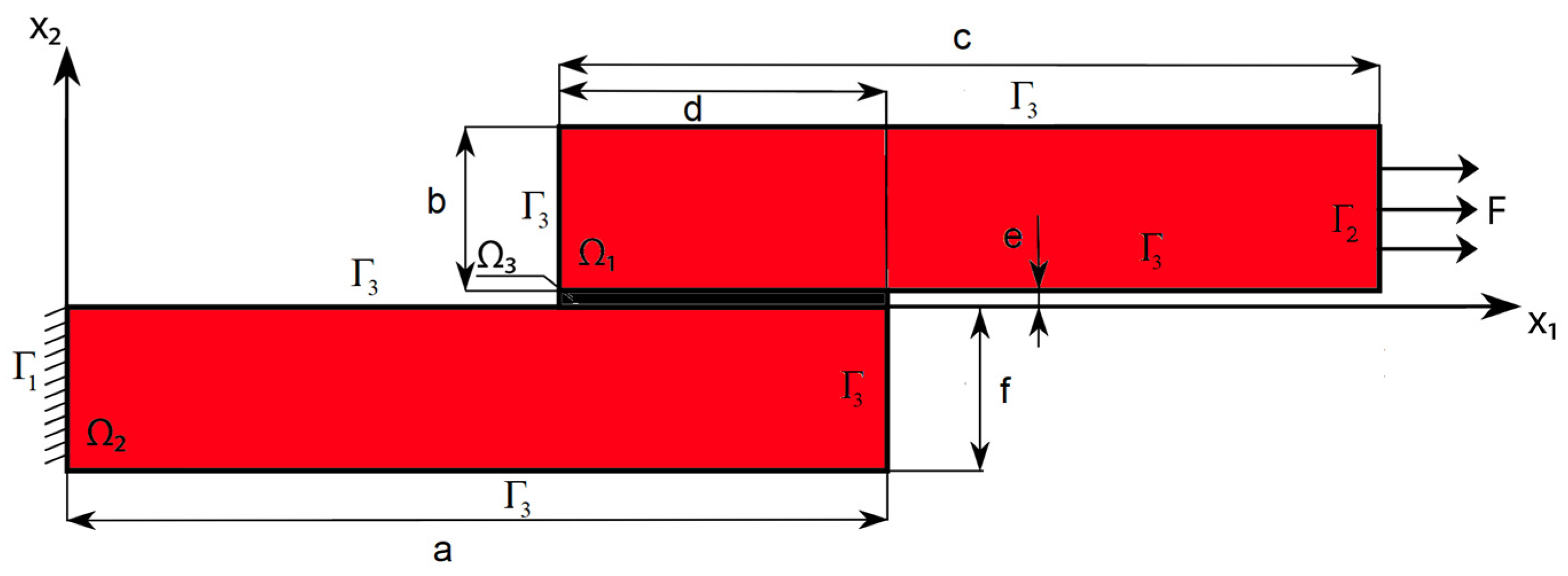
2.1. Statement of the Direct Problem
2.2. Statement of the Topological Optimization Problem
3. Numerical Results
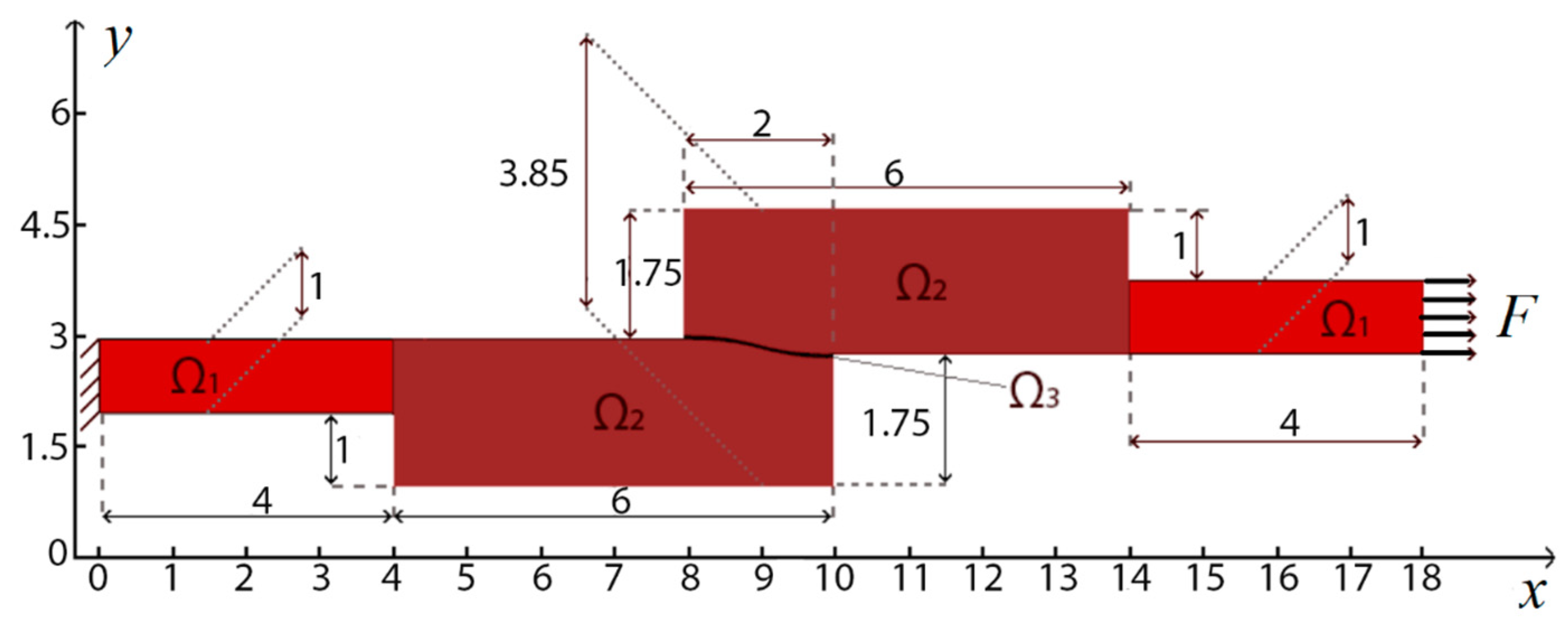
3.1. Case Study 1. Optimization of the Lap Joint of a Two-Layer Package
3.2. Case Study 2: Optimization of a Design Consisting of Three Parts Connected with an Overlap
4. Conclusions
Author Contributions
Funding
Institutional Review Board Statement
Informed Consent Statement
Data Availability Statement
Conflicts of Interest
References
- Kumar, V.K.; Rao, M.V. Some studies and analysis of adhesive bonded joints: A review. J. Chin. Adv. Mater. Soc. 2017, 5, 241–253. [Google Scholar] [CrossRef]
- Patel, P.; Varikoti, P.; Lama, K. Applications of Composite Material in Aerospace Industry. 2015. Available online: https://dokumen.tips/engineering/application-of-composite-materials-in-aerospace-industry-1.html?page=1 (accessed on 13 March 2023).
- He, X. A review of finite element analysis of adhesively bonded joints. Int. J. Adhes. Adhes. 2011, 31, 248–264. [Google Scholar] [CrossRef]
- Banea, M.D.; da Silva, L.F.M. Adhesively bonded joints in composite materials: An overview. Proc. Inst. Mech. Eng. Part L J. Mater. Des. Appl. 2009, 223, 1–18. [Google Scholar] [CrossRef]
- Kahraman, R.; Sunar, M.; Yilbas, B. Influence of adhesive thickness and filler content on the mechanical performance of aluminum single lap-joints bonded with aluminum powder filled epoxy adhesive. J. Mater. Process. Technol. 2008, 205, 183–189. [Google Scholar] [CrossRef]
- Grant, L.D.R.; Adams, R.D.; da Silva, L.F.M. Experimental and numerical analysis of single-lap joints for the automotive industry. Int. J. Adhes. Adhes. 2009, 29, 405–413. [Google Scholar] [CrossRef]
- Vinay, M.N. Optimization of adhesive bonding parameters of aluminium 6082 joints. AIP Conf. Proc. 2021, 2317, 020042. [Google Scholar] [CrossRef]
- Yaman, M.; Şansveren, M.F. Numerical and experimental vibration analysis of different types of adhesively bonded joints. Structures 2021, 34, 368–380. [Google Scholar] [CrossRef]
- Kemiklioglu, U.; Baba, O.B. Vibration effects on tensile properties of adhesively bonded single lap joints in composite materials. Polym. Compos. 2019, 40, 1258–1267. [Google Scholar] [CrossRef]
- Yaman, M.; Şansveren, M.F.; Maraş, S. Vibration characteristics analysis of adhesively bonded different joints. Turk. J. Electromech. Energy 2020, 5, 21–28. [Google Scholar]
- Almitani, K.H.; Othman, R. Analytical solution of the harmonic response of viscoelastic adhesively bonded single-lap and double-lap joints. Int. J. Adhes. Adhes. 2016, 71, 55–65. [Google Scholar] [CrossRef]
- Machado, D.M.S.R.B.; Campilho, R.D.S.G.; Cardoso, M.G. Impact modelling of single-lap bonded joints by cohesive zone models. Procedia Manuf. 2019, 41, 34–41. [Google Scholar] [CrossRef]
- Dragoni, E.; Brinson, H.F. Modeling and optimization of the sandwich beam specimen in three-point bending for adhesive bond characterization. Int. J. Adhes. Adhes. 2016, 68, 380–388. [Google Scholar] [CrossRef]
- Fedorov, A.Y.; Matveenko, V.P. Designing of interlayers between materials with minimum stress level at the interface. Int. J. Adhes. Adhes. 2021, 111, 102963. [Google Scholar] [CrossRef]
- Valente, J.P.A.; Campilho, R.D.S.G.; Marques, E.A.S.; Machado, J.J.M.; da Silva, L.F.M. Geometrical optimization of adhesive joints under tensile impact loads using cohesive zone modeling. Int. J. Adhes. Adhes. 2020, 97, 102492. [Google Scholar] [CrossRef]
- Valente, J.P.A.; Campilho, R.D.S.G.; Marques, E.A.S.; Machado, J.J.M.; da Silva, L.F.M. Adhesive joint analysis under tensile impact loads by cohesive zone modelling. Compos. Struct. 2019, 222, 110894. [Google Scholar] [CrossRef]
- Ejaza, H.; Mubashara, A.; Ashcroftb, I.A.; Uddina, E.; Khanc, M. Topology optimisation of adhesive joints using non-parametric methods. Int. J. Adhes. Adhes. 2018, 81, 1–10. [Google Scholar] [CrossRef]
- de Vicente, M. Numerical optimization of hybrid panel joints by mixed adhesive/welded method on shipbuilding. In Proceedings of the ASME 2018 37th International Conference on Ocean, Offshore and Arctic Engineering OMAE2018, Madrid, Spain, 17–22 June 2018. [Google Scholar] [CrossRef]
- de Vicente, M.; Silva-Campillo, A.; Herreros, M.Á.; Suárez-Bermejo, J.C. Design of a structurally welded/adhesively bonded joint between a fiber metal laminate and a steel plate for marine applications. J. Mar. Sci. Technol. 2022, 27, 1002–1014. [Google Scholar] [CrossRef]
- Kim, C.; Seong, H.K.; Kim, I.Y.; Yoo, J. Single variable-based multi-material structural optimization considering interface behavior. Comput. Methods Appl. Mech. Engrg. 2020, 367, 113114. [Google Scholar] [CrossRef]
- Arhore, E.G.; Yasaee, M.; Dayyani, I. Comparison of GA and topology optimization of adherend for adhesively bonded metal composite joints. Int. J. Solids Struct. 2021, 226–227, 111078. [Google Scholar] [CrossRef]
- Mallick, P.K. Optimization of Structural Adhesive Joints. In Structural Adhesive Joints: Design, Analysis and Testing; Mittal, K.L., Panigrahi, S.K., Eds.; Wiley: Hoboken, NJ, USA, 2020. [Google Scholar] [CrossRef]
- Hamdia, K.M.; Ghasemi, H.; Zhuang, X.; Rabczuk, T. Multilevel Monte Carlo method for topology optimization of flexoelectric composites with uncertain material properties. Eng. Anal. Bound. Elem. 2022, 134, 412–418. [Google Scholar] [CrossRef]
- Awrejcewicz, J.; Pavlov, S.P.; Krysko, A.V.; Zhigalov, M.V.; Bodyagina, K.S.; Krysko, V.A. Decreasing Shear Stresses of the Solder Joints for Mechanical and Thermal Loads by Topological Optimization. Materials 2020, 13, 1862. [Google Scholar] [CrossRef] [PubMed]
- Krysko, A.V.; Awrejcewicz, J.; Dunchenkin, P.V.; Zhigalov, M.V.; Krysko, V.A. Topological Optimization of Multilayer Structural Elements of MEMS/NEMS Resonators with an Adhesive Layer Subjected to Mechanical Loads. In Recent Approaches in the Theory of Plates and Plate-like Structures. Advanced Structured Materials; Altenbach, H., Bauer, S., Eremeyev, V.A., Mikhasev, G.I., Morozov, N.F., Eds.; Springer: Cham, Switzerland, 2022; Volume 151. [Google Scholar] [CrossRef]
- Brackett, D.; Panesar, A.; Ashcroft, I.; Wildman, R.; Hague, R. An optimisation based design framework for multifunctional 3D printing. In 24th Annual International Solid Freeform Fabrication Symposium: An Additive Manufacturing Conference, Proceedings, 12–14 August 2013; Solid Freeform Fabrication Proceedings; University of Texas: Austin, TX, USA, 2013; ISSN 1053-2153. [Google Scholar]
- Tang, Y.; Zhao, Y.F. A survey of the design methods for additive manufacturing to improve functional performance. Rapid Prototyp. J. 2016, 22, 569–590. [Google Scholar] [CrossRef]
- Panesar, A.; Brackett, D.; Ashcroft, I.; Wildman, R.; Hague, R. Design Framework for Multifunctional Additive Manufacturing: Placement and Routing of Three-Dimensional Printed Circuit Volumes. ASME J. Mech. Des. 2015, 137, 111414. [Google Scholar] [CrossRef]
- Ozguc, S.; Pan, L.; Weibel, J.A. Topology optimization of microchannel heat sinks using a homogenization approach. Int. J. Heat Mass Transf. 2021, 169, 120896. [Google Scholar] [CrossRef]
- Gu, X.; He, S.; Dong, Y.; Song, T. An improved ordered SIMP approach for multiscale concurrent topology optimization with multiple microstructures. Compos. Struct. 2022, 287, 115363. [Google Scholar] [CrossRef]
- Kotarski, D.; Piljek, P.; Pranjić, M.; Grlj, C.G.; Kasać, J. A Modular Multirotor Unmanned Aerial Vehicle Design Approach for Development of an Engineering Education Platform. Sensors 2021, 21, 2737. [Google Scholar] [CrossRef]
- Chen, Z.; Rahimi Nohooji, H.; Chew, C. Development of Topology Optimized Bending-Twisting Soft Finger. J. Mech. Robot. 2021, 14, 051003. [Google Scholar] [CrossRef]
- Tyflopoulos, E.; Steinert, M. A Comparative Study of the Application of Different Commercial Software for Topology Optimization. Appl. Sci. 2022, 12, 611. [Google Scholar] [CrossRef]
- Bendsøe, M.P.; Sigmund, O. Topology Optimization. In Theory, Methods and Applications; Springer: Berlin/Heidelberg, Germany, 2004. [Google Scholar] [CrossRef]
- Awrejcewicz, J.; Pavlov, S.P.; Bodyagina, K.S.; Zhigalov, M.V.; Krysko, V.A. Design of composite structures with extremal elastic properties in the presence of technological constraints. Compos. Struct. 2017, 174, 19–25. [Google Scholar] [CrossRef]
- Krysko, A.V.; Awrejcewicz, J.; Pavlov, S.P.; Bodyagina, K.S.; Zhigalov, M.V.; Krysko, V.A. Non-linear dynamics of size-dependent Euler–Bernoulli beams with topologically optimized microstructure and subjected to temperature field. Int. J. Non-Linear Mech. 2018, 104, 75–86. [Google Scholar] [CrossRef]
- Krysko, A.; Awrejcewicz, J.; Bodyagina, K.; Makseev, A.; Zhigalov, M.; Krysko, V. Identifying inclusions in a non-uniform thermally conductive plate under external flows and internal heat sources using topological optimization. Math. Mech. Solids 2022, 27, 1649–1671. [Google Scholar] [CrossRef]
- Krysko, A.V.; Makseev, A.; Smirnov, A.; Zhigalov, M.V.; Krysko, V.A. A New Approach to Identifying an Arbitrary Number of Inclusions, Their Geometry and Location in the Structure Using Topological Optimization. Appl. Sci. 2023, 13, 49. [Google Scholar] [CrossRef]

 —nonoptimizated area,
  —optimizated area,
  —adhesive.
—nonoptimizated area, —optimizated area, —adhesive.
—adhesive.
—nonoptimizated area, —optimizated area, —adhesive.
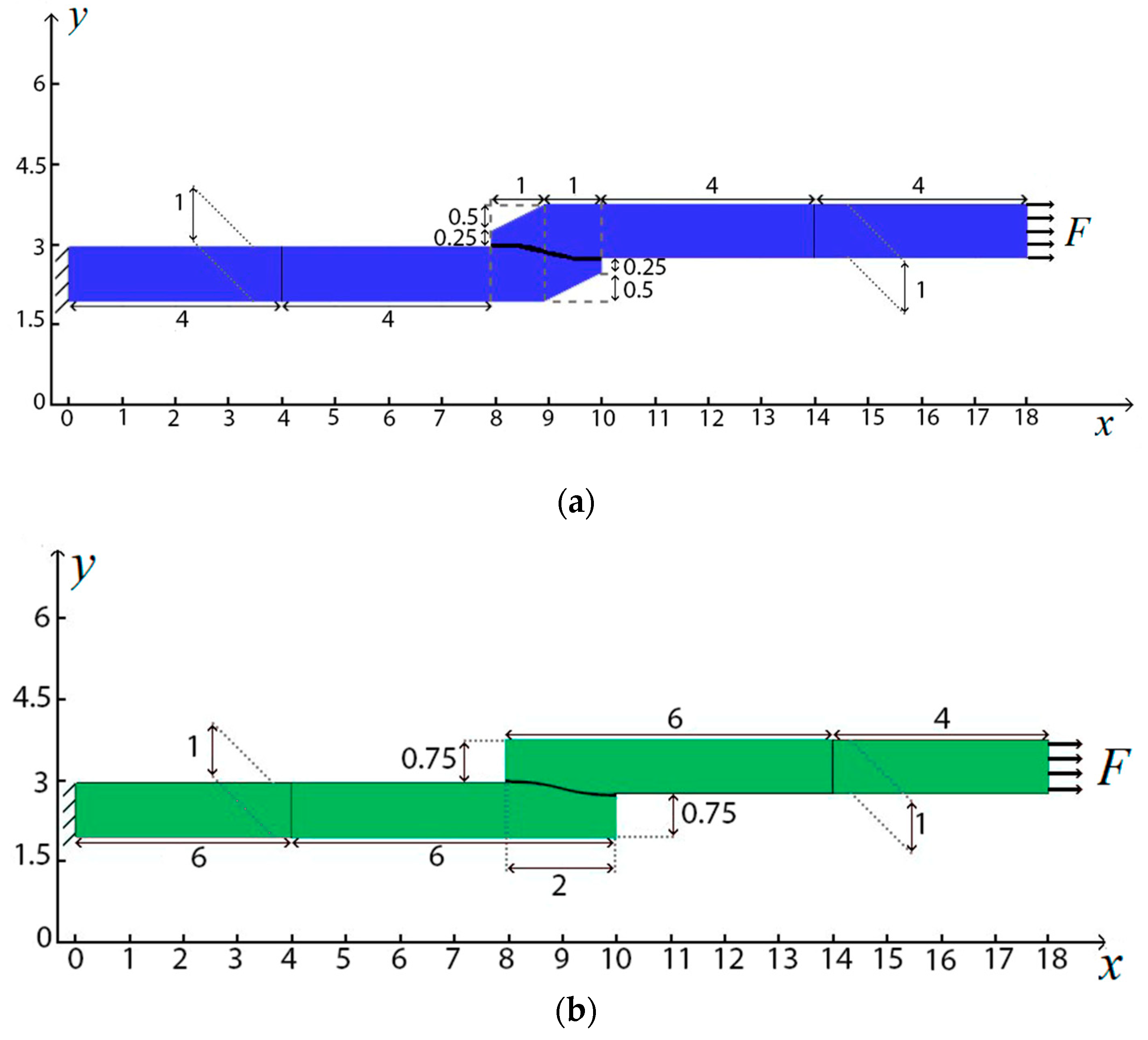
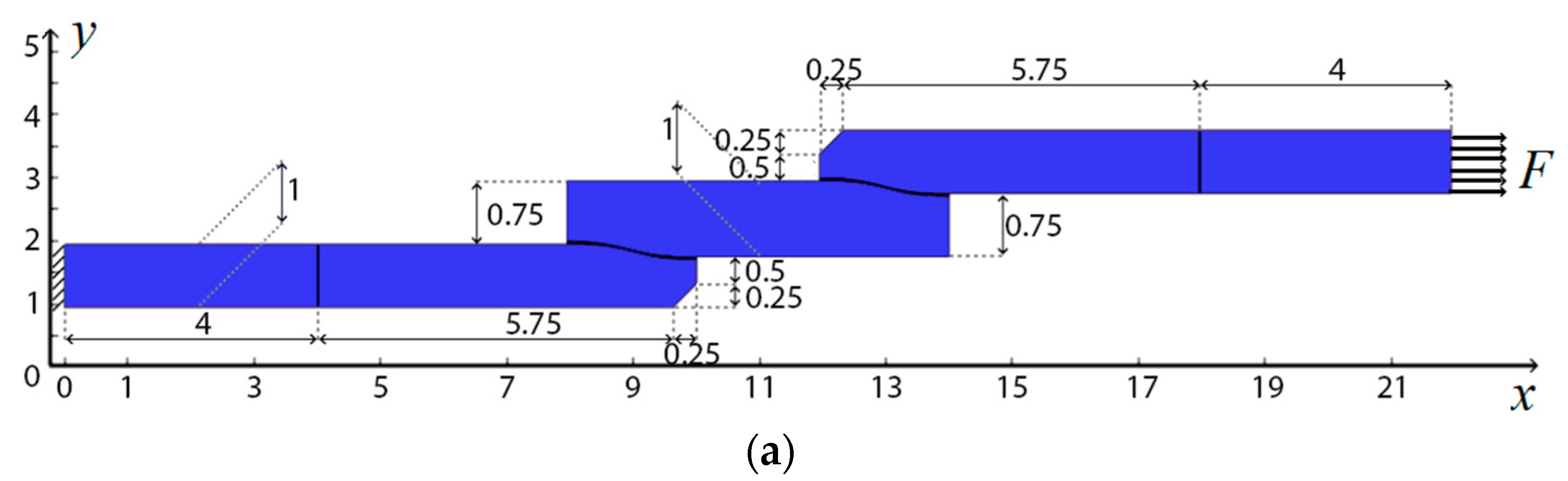
 Classic type of connection with bevel (B); (b)
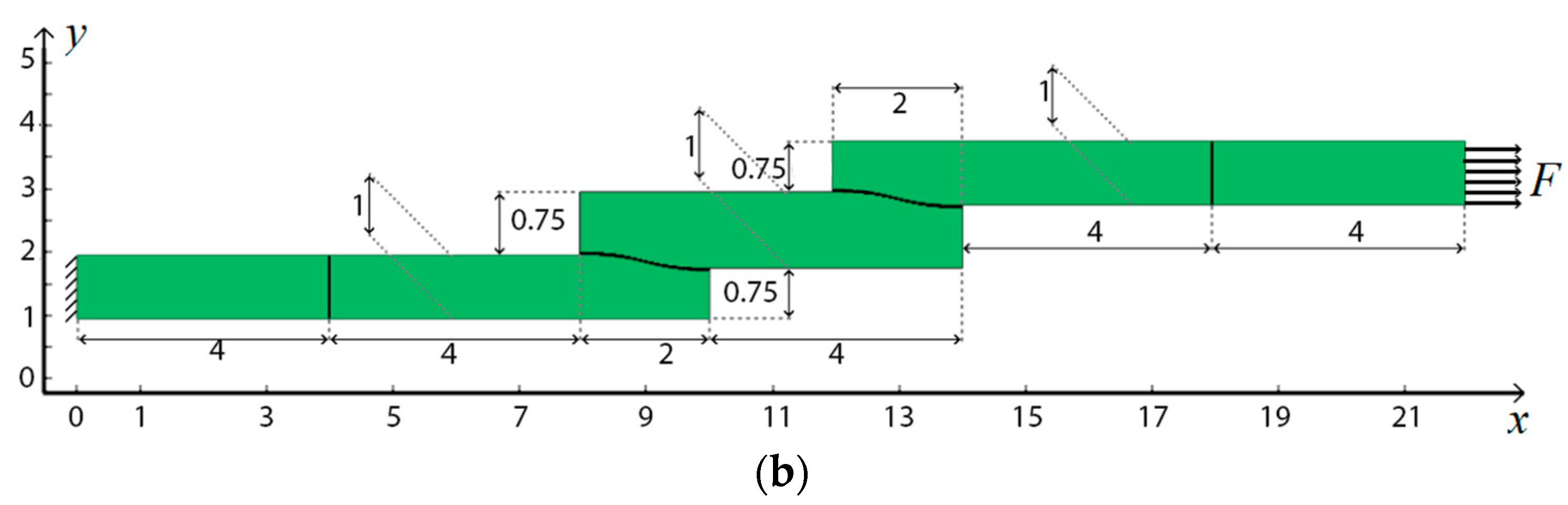
  Classical connection without bevel (C).
Classic type of connection with bevel (B); (b) Classical connection without bevel (C).
Classical connection without bevel (C).
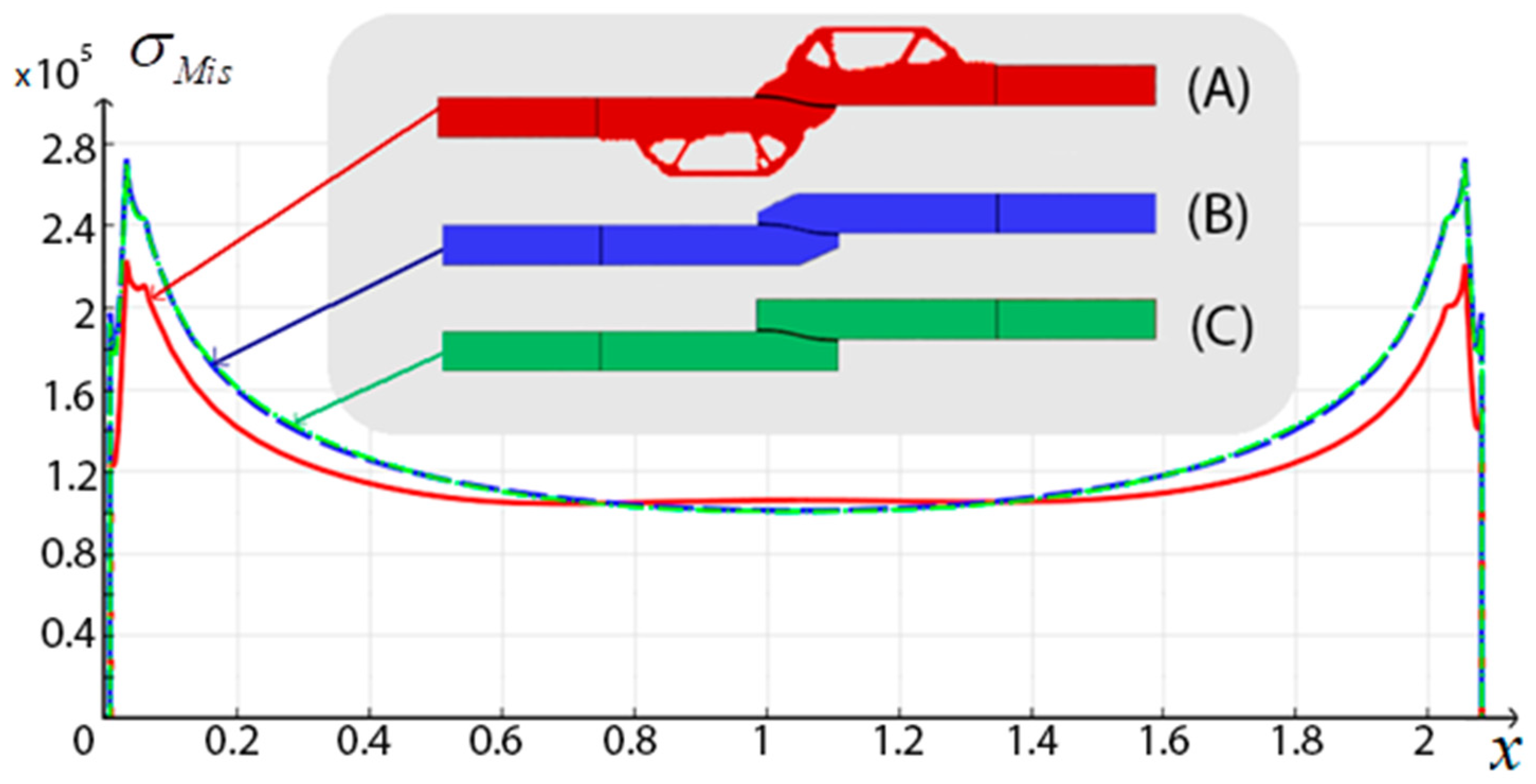
Classic type of connection with bevel (B); (b) Classical connection without bevel (C). optimal design, (B) Classic type of connection with bevel, (C) Classic type of connection without bevel.
optimal design, (B) Classic type of connection with bevel, (C) Classic type of connection without bevel.
optimal design, (B) Classic type of connection with bevel, (C) Classic type of connection without bevel. optimal design, (B) Classic type of connection with bevel, (C) Classic type of connection without bevel.
optimal design, (B) Classic type of connection with bevel, (C) Classic type of connection without bevel.
optimal design, (B) Classic type of connection with bevel, (C) Classic type of connection without bevel. optimal design, Classic type of connection with bevel, Classic type of connection without bevel.
optimal design, Classic type of connection with bevel, Classic type of connection without bevel.
optimal design, Classic type of connection with bevel, Classic type of connection without bevel. Classic type of connection with bevel (B); (b) Classical connection without bevel (C).
Classic type of connection with bevel (B); (b) Classical connection without bevel (C).
Classic type of connection with bevel (B); (b) Classical connection without bevel (C).

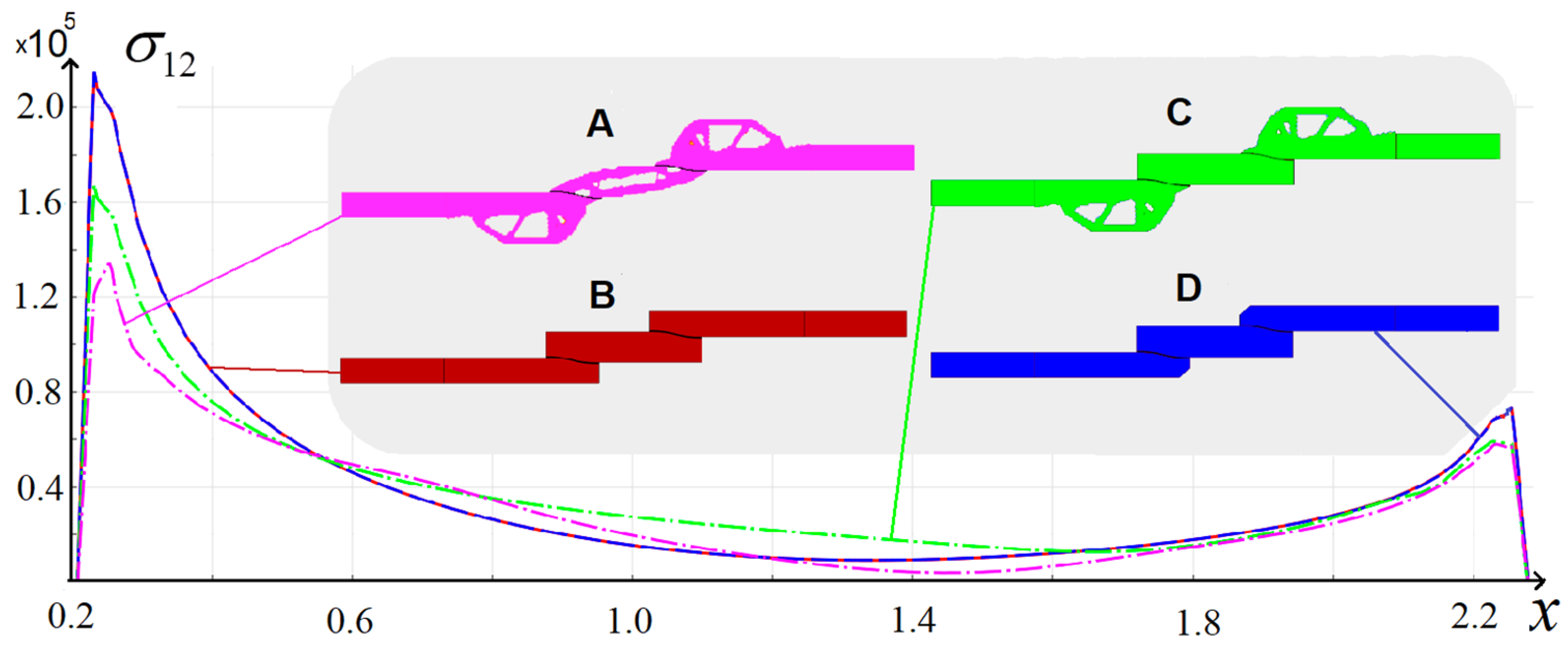
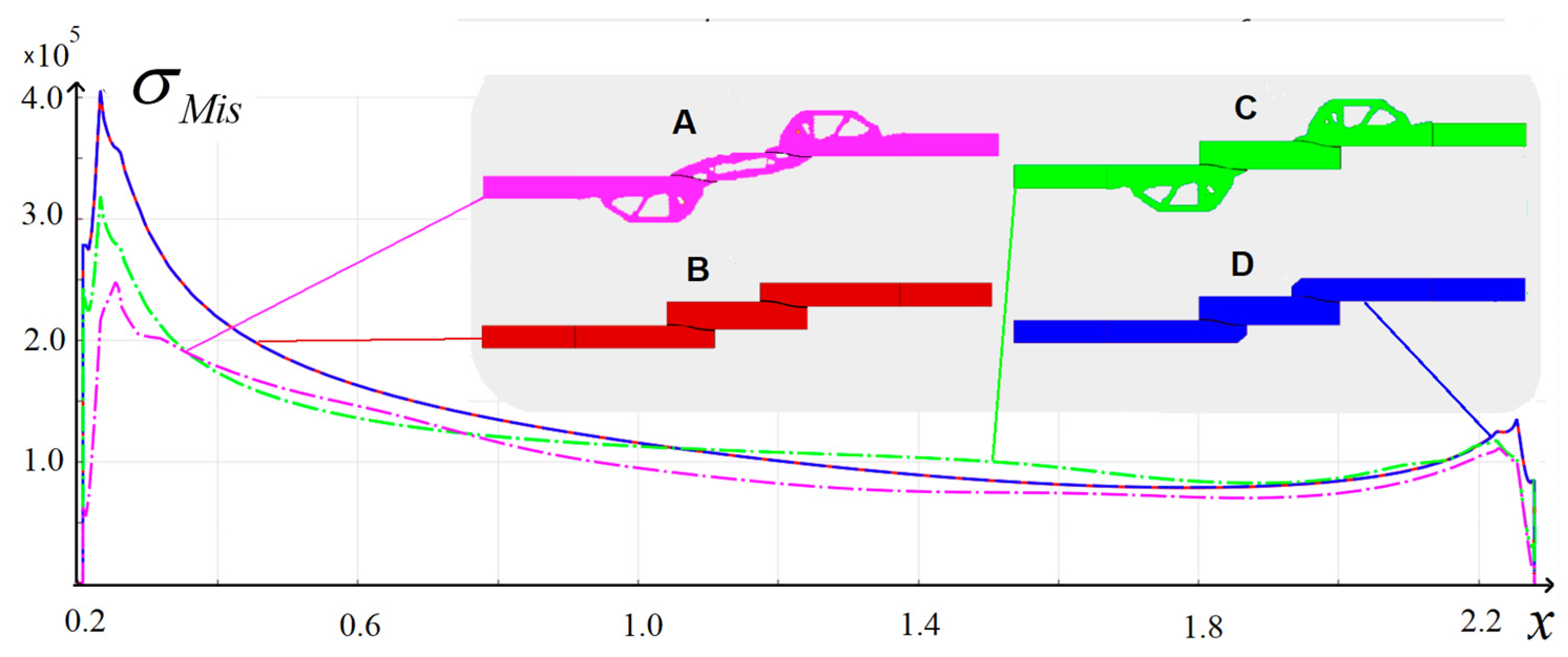
 optimal design I, (B) Classic type of connection without bevel, (C) optimal design II, (D) Classic type of connection with bevel.
optimal design I, (B) Classic type of connection without bevel, (C) optimal design II, (D) Classic type of connection with bevel.
optimal design I, (B) Classic type of connection without bevel, (C) optimal design II, (D) Classic type of connection with bevel. optimal design I, (B) Classic type of connection without bevel, (C) optimal design II, (D) Classic type of connection with bevel.
optimal design I, (B) Classic type of connection without bevel, (C) optimal design II, (D) Classic type of connection with bevel.
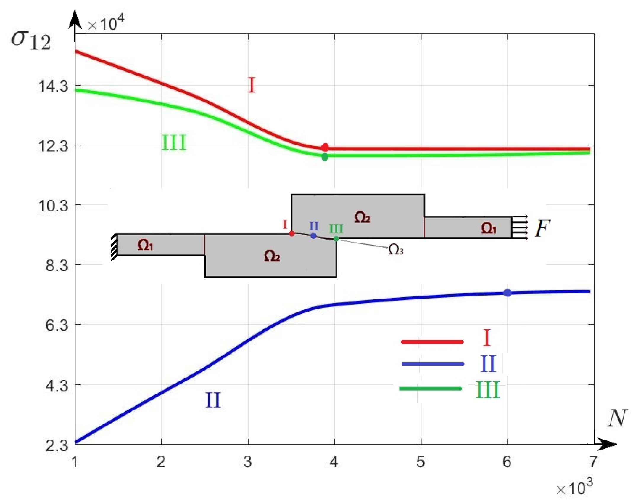
optimal design I, (B) Classic type of connection without bevel, (C) optimal design II, (D) Classic type of connection with bevel. left border of adhesive, center point of adhesive, right border of adhesive.
left border of adhesive, center point of adhesive, right border of adhesive.
left border of adhesive, center point of adhesive, right border of adhesive.

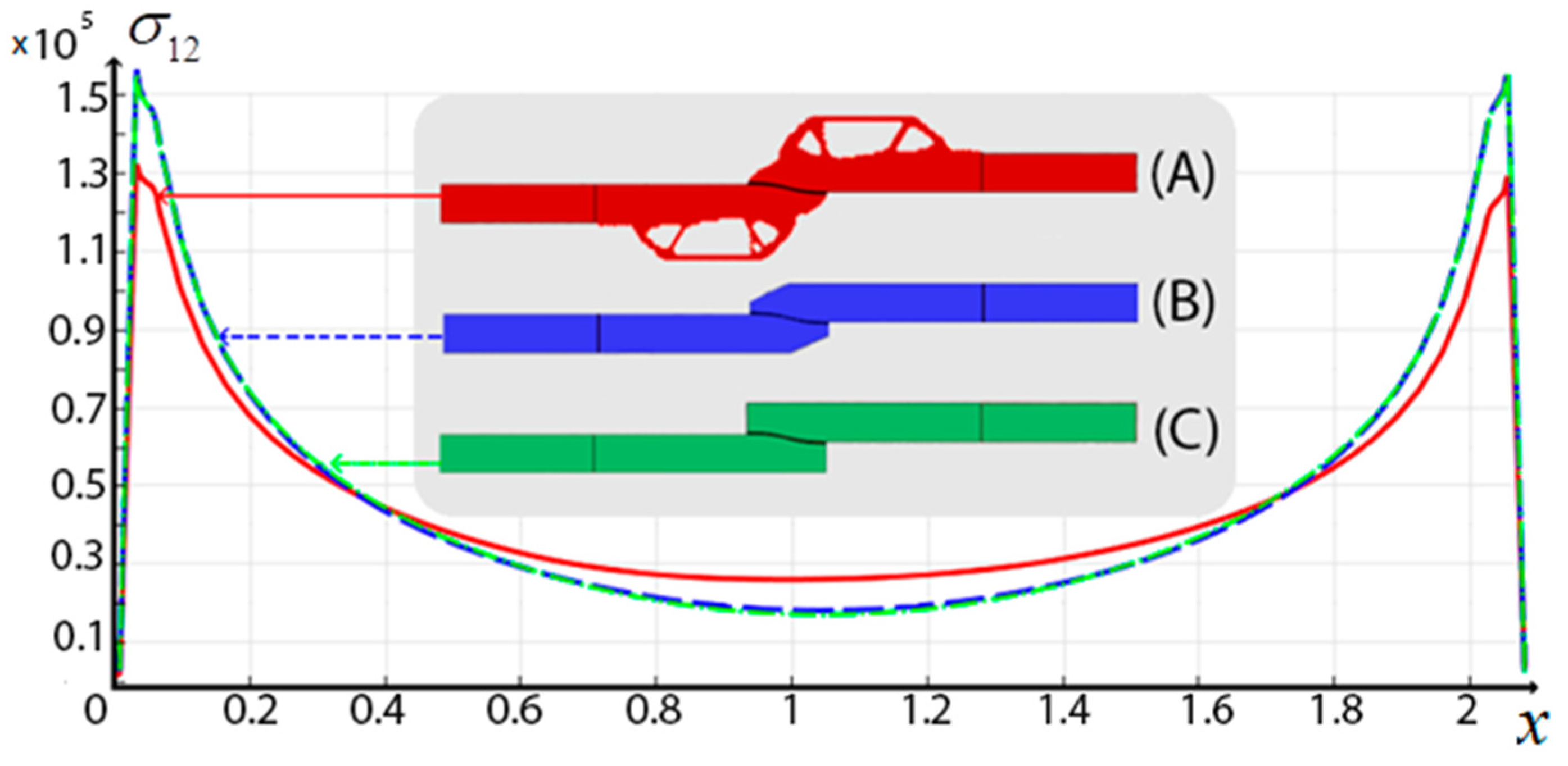
| Construction | Maximum Value in Solder | Maximum Shear Stresses σ12 in Solder |
|---|---|---|
| Topologically optimal construction (A) | 225,356 | 121,540 |
| Bevel (engineering option to reduce the shear stress) (B) | 279,400 | 144,320 |
| Straight (initial design) (C) | 279,250 | 143,941 |
optimal design, Classic type of connection with bevel, Classic type of connection within bevel.
optimal design, Classic type of connection with bevel, Classic type of connection within bevel.
Visualisation of the FE Approximation of an Overlapping Joint between Two Beams | Number of El-ements N × 103 | Maximum Stress × 105 | Number of Iterations n | I × 105 | II × 105 | III × 105 |
|---|---|---|---|---|---|---|
 | 6.96 | 1.214 | 83 | 1.214 | 0.739 | 1.202 |
 | 3.94 | 1.215 | 82 | 1.215 | 0.693 | 1.192 |
 | 2.31 | 1.399 | 71 | 1.399 | 0.45 | 1.345 |
 | 1.0 | 1.541 | 61 | 1.541 | 0.235 | 1.411 |
| Construction | Maximum Value σMis in Solder | Maximum Shear Stresses σ12 in Solder |
|---|---|---|
| Straight (initial design) (B) | 479,365 | 243,695 |
| Bevel (engineering option to reduce to shear stresses) (D) | 479,840 | 244,341 |
| Topologically optimal design II (C) | 325,920 | 221,236 |
| Topologically optimal design I (A) | 247,865 | 134,625 |
left border of adhesive, center point of adhesive, right border of adhesive.
left border of adhesive, center point of adhesive, right border of adhesive.
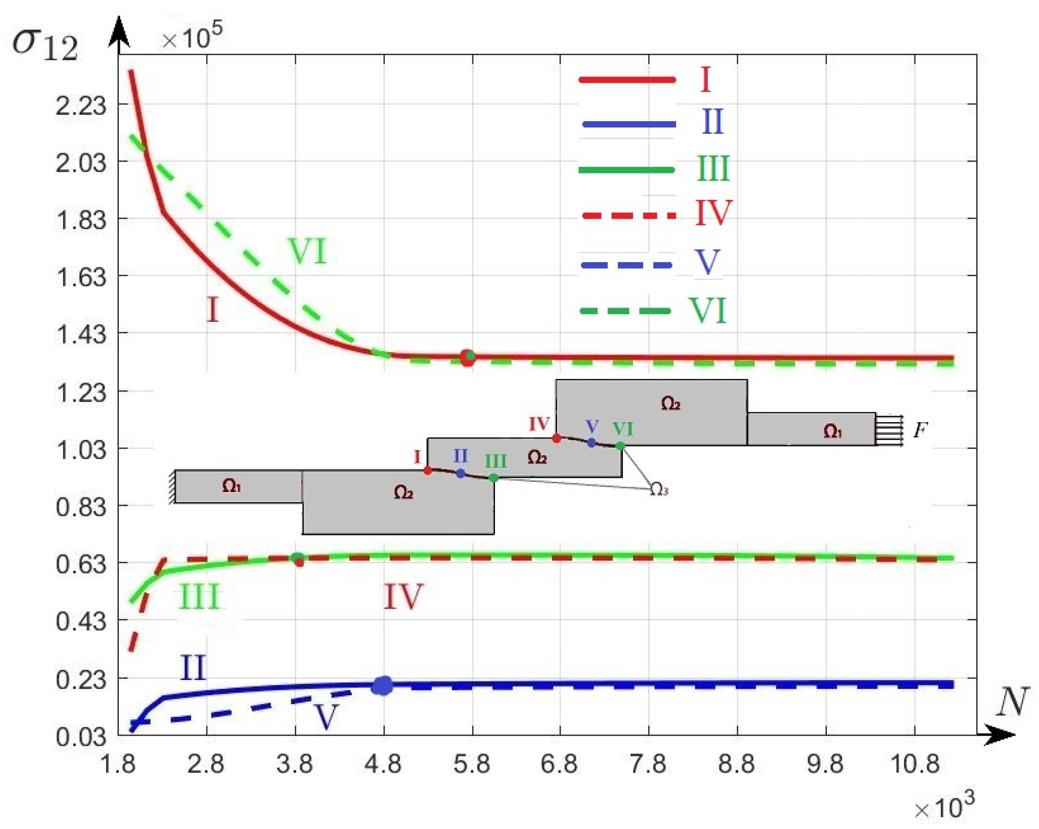
Visualisation of the FE Approximation of an Overlap Joint between Two Beams | Number of Elements N × 103 | Maximum Stress maxσ12 × 105 |
Number of Iterations n | I × 105 | II × 105 | III × 105 | IV × 105 | V ×10 5 | VI ×10 5 |
|---|---|---|---|---|---|---|---|---|---|
 | 11.20 | 1.341 | 171 | 1.341 | 0.211 | 0.644 | 0.638 | 0.198 | 1.32 |
 | 5.18 | 1.346 | 164 | 1.346 | 0.205 | 0.655 | 0.645 | 0.193 | 1.331 |
 | 2.31 | 1.995 | 146 | 1.852 | 0.157 | 0.595 | 0.637 | 0.078 | 1.995 |
 | 1.94 | 2.345 | 145 | 2.345 | 0.038 | 0.489 | 0.317 | 0.071 | 2.116 |
Disclaimer/Publisher’s Note: The statements, opinions and data contained in all publications are solely those of the individual author(s) and contributor(s) and not of MDPI and/or the editor(s). MDPI and/or the editor(s) disclaim responsibility for any injury to people or property resulting from any ideas, methods, instructions or products referred to in the content. |
© 2023 by the authors. Licensee MDPI, Basel, Switzerland. This article is an open access article distributed under the terms and conditions of the Creative Commons Attribution (CC BY) license (https://creativecommons.org/licenses/by/4.0/).
Share and Cite
Dunchenkin, P.V.; Cherekaeva, V.A.; Yakovleva, T.V.; Krysko, A.V. Topological Optimization of Interconnection of Multilayer Composite Structures. Computation 2023, 11, 87. https://doi.org/10.3390/computation11050087
Dunchenkin PV, Cherekaeva VA, Yakovleva TV, Krysko AV. Topological Optimization of Interconnection of Multilayer Composite Structures. Computation. 2023; 11(5):87. https://doi.org/10.3390/computation11050087
Chicago/Turabian StyleDunchenkin, P. V., V. A. Cherekaeva, T. V. Yakovleva, and A. V. Krysko. 2023. "Topological Optimization of Interconnection of Multilayer Composite Structures" Computation 11, no. 5: 87. https://doi.org/10.3390/computation11050087