

Computational Investigation of Dental Implant Restoration Using Platform-Switched and -Matched Configurations

Abstract
:1. Introduction
2. Materials and Methods
- PS I: platform switching of 0.85 mm using 3.8 mm diameter abutment;
- PS II: platform switching of 0.5 mm using 4.5 mm diameter abutment;
- PM: no platform switching (platform matching) using 5.5 mm diameter abutment.
3. Results
3.1. Stress Analysis
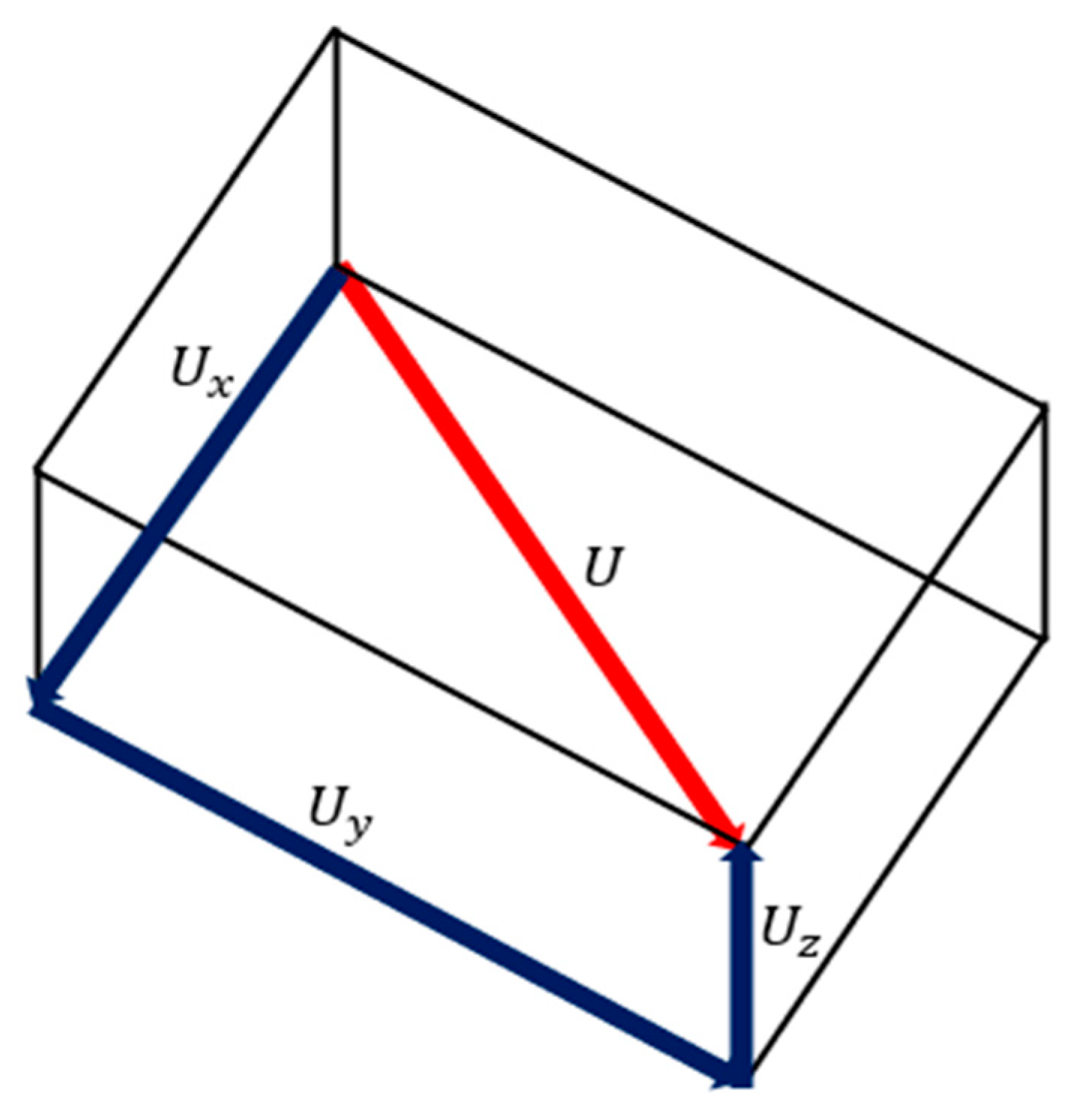
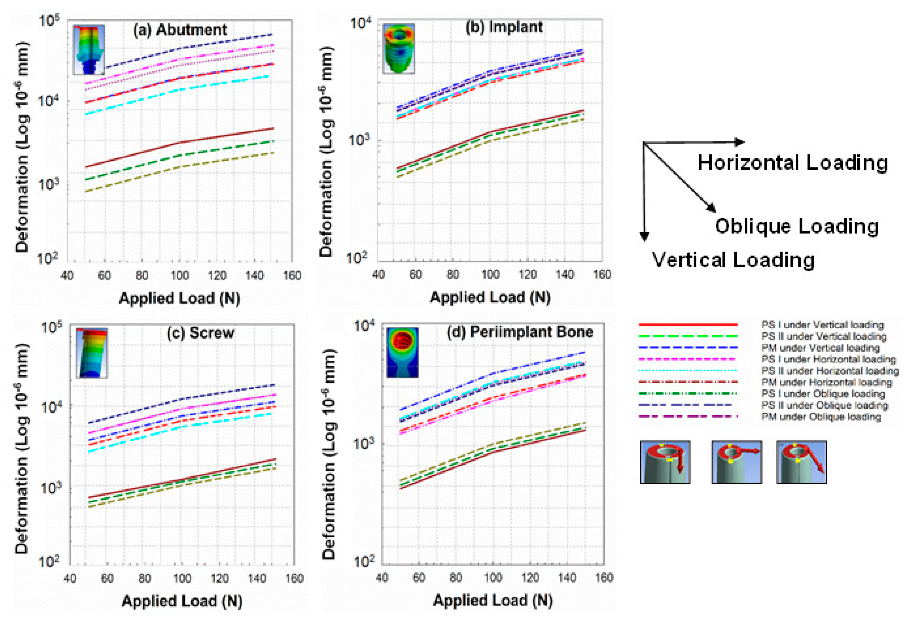
3.2. Deformation Analysis
3.3. Strain Energy Analysis
4. Discussion
5. Conclusions
Author Contributions
Funding
Data Availability Statement
Conflicts of Interest
References
- Jemt, T.; Lekholm, U.; Gröndahl, K. 3-year followup study of early single implant restorations ad modum Brånemark. Int. J. Periodontics Restor. Dent. 1990, 10, 340–349. [Google Scholar]
- Baqain, Z.H.; Moqbel, W.Y.; Sawair, F.A. Early dental implant failure: Risk factors. Br. J. Oral Maxillofac. Surg. 2012, 50, 239–243. [Google Scholar] [CrossRef] [PubMed]
- Vigolo, P.; Givani, A. Platform-switched restorations on wide-diameter implants: A 5-year clinical prospective study. Int. J. Oral Maxillofac. Implant. 2009, 24, 103–109. [Google Scholar]
- Canullo, L.; Rossi-Fedele, G.; Iannello, G.; Jepsen, S. Platform switching and marginal bone-level alterations: The results of a randomized-controlled trial. Clin. Oral Implant. Res. 2010, 21, 115–121. [Google Scholar] [CrossRef]
- Al-Nsour, M.M.; Chan, H.-L.; Wang, H.-L. Effect of the platform-switching technique on preservation of peri-implant marginal bone: A systematic review. Int. J. Oral Maxillofac. Implant. 2012, 27, 138–145. [Google Scholar]
- Strietzel, F.P.; Neumann, K.; Hertel, M. Impact of platform switching on marginal peri-implant bone-level changes. A systematic review and meta-analysis. Clin. Oral Implant. Res. 2015, 26, 342–358. [Google Scholar] [CrossRef] [Green Version]
- Heckmann, S.; Linke, J.; Graef, F.; Foitzik, C.; Wichmann, M.; Weber, H.-P. Stress and inflammation as a detrimental combination for peri-implant bone loss. J. Dent. Res. 2006, 85, 711–716. [Google Scholar] [CrossRef] [Green Version]
- Khraisat, A.; Abu-Hammad, O.; Al-Kayed, A.M.; Dar-Odeh, N. Stability of the Implant/Abutment Joint in a Single-Tooth External-Hexagon Implant System: Clinical and Mechanical Review. Clin. Implant. Dent. Relat. Res. 2004, 6, 222–229. [Google Scholar] [CrossRef]
- Wu, A.Y.-J.; Huang, H.-L.; Hsu, J.-T.; Chee, W. Biomechanical effects of the implant material and implant–abutment interface in immediately loaded small-diameter implants. Clin. Oral Investig. 2014, 18, 1335–1341. [Google Scholar] [CrossRef]
- Wu, A.Y.-J.; Hsu, J.-T.; Huang, H.-L. An In Vitro Biomechanical Evaluation of a New Commercial Titanium-Zirconium Alloy Dental Implant. Implant. Dent. 2014, 23, 534–538. [Google Scholar] [CrossRef]
- Hegde, C.; Prasad, K.D.; Shetty, M.; Bansal, N. Platform switching: An answer to crestal bone loss. J. Dent. Implant. 2011, 1, 13. [Google Scholar] [CrossRef]
- Grunder, U.; Gracis, S.; Capelli, M. Influence of the 3-D bone-to-implant relationship on esthetics. Int. J. Periodontics Restor. Dent. 2005, 25, 113–119. [Google Scholar]
- Baggi, L.; Cappelloni, I.; Di Girolamo, M.; Maceri, F.; Vairo, G. The influence of implant diameter and length on stress distribution of osseointegrated implants related to crestal bone geometry: A three-dimensional finite element analysis. J. Prosthet. Dent. 2008, 100, 422–431. [Google Scholar] [CrossRef] [Green Version]
- Lazzara, R.J.; Porter, S.S. Platform switching: A new concept in implant dentistry for controlling postrestorative crestal bone levels. Int. J. Periodontics Restor. Dent. 2006, 26, 9–17. [Google Scholar]
- Vela-Nebot, X.M.; Rodríguez-Ciurana, X.; Rodado-Alonso, C.; Segalà-Torres, M.M. Benefits of an Implant Platform Modification Technique to Reduce Crestal Bone Resorption. Implant. Dent. 2006, 15, 313–320. [Google Scholar] [CrossRef]
- Cocchetto, R.; Traini, T.; Caddeo, F.; Celletti, R. Evaluation of hard tissue response around wider platform-switched im-plants. Int. J. Periodontics Restor. Dent. 2010, 30, 163–171. [Google Scholar]
- Enkling, N.; Jöhren, P.; Klimberg, V.; Bayer, S.; Mericske-Stern, R.; Jepsen, S. Effect of platform switching on peri-implant bone levels: A randomized clinical trial. Clin. Oral Implant. Res. 2011, 22, 1185–1192. [Google Scholar] [CrossRef]
- Knop, L.; Gandini, L.G., Jr.; Shintcovsk, R.L.; Gandini, M.R.E.A.S. Scientific use of the finite element method in Orthodontics. Dent. Press J. Orthod. 2015, 20, 119–125. [Google Scholar] [CrossRef]
- Matsuoka, T.; Nakano, T.; Yamaguchi, S.; Ono, S.; Watanabe, S.; Sato, T.; Yatani, H. Effects of Implant–Abutment Connection Type and Inter-Implant Distance on Inter-Implant Bone Stress and Microgap: Three-Dimensional Finite Element Analysis. Materials 2021, 14, 2421. [Google Scholar] [CrossRef]
- Reddy, M.S.; Sundram, R.; Abdemagyd, H.A.E. Application of finite element model in implant dentistry: A systematic review. J. Pharm. Bioallied Sci. 2019, 11, S85–S91. [Google Scholar] [CrossRef]
- Romanyk, D.L.; Vafaeian, B.; Addison, O.; Adeeb, S. The use of finite element analysis in dentistry and orthodontics: Critical points for model development and interpreting results. Semin. Orthod. 2020, 26, 162–173. [Google Scholar] [CrossRef]
- Bandgar, V.; Kharsan, V.; Mirza, A.; Jagtiani, K.; Dhariwal, N.; Kore, R. Comparative evaluation of three abutment–implant interfaces on stress distribution in and around different implant systems: A finite element analysis. Contemp. Clin. Dent. 2019, 10, 590–594. [Google Scholar] [CrossRef] [PubMed]
- Pournasrollah, A.; Negahdari, R.; Gharekhani, V.; Torab, A.; Ataei, S.J. Investigating the effect of abutment–implant connection type on abutment screw loosening in a dental implant system using finite element method. J. Dent. Res. Dent. Clin. Dent. Prospect. 2019, 13, 289–297. [Google Scholar] [CrossRef] [PubMed] [Green Version]
- Cho, S.-Y.; Huh, Y.-H.; Park, C.-J.; Cho, L.-R. Three-Dimensional Finite Element Analysis of the Stress Distribution at the Internal Implant-Abutment Connection. Int. J. Periodontics Restor. Dent. 2016, 36, e49–e58. [Google Scholar] [CrossRef] [Green Version]
- Anitua, E.; de Ibarra, N.L.S.; Martín, I.M.; Rotaeche, L.S. Influence of Dental Implant Diameter and Bone Quality on the Biomechanics of Single-Crown Restoration. A Finite Element Analysis. Dent. J. 2021, 9, 103. [Google Scholar] [CrossRef]
- Fiorillo, L.; Cicciù, M.; D’Amico, C.; Mauceri, R.; Oteri, G.; Cervino, G. Finite Element Method and Von Mises Investigation on Bone Response to Dynamic Stress with a Novel Conical Dental Implant Connection. BioMed Res. Int. 2020, 2020, 2976067. [Google Scholar] [CrossRef]
- Cumbo, C.; Marigo, L.; Somma, F.; La Torre, G.; Minciacchi, I.; D’Addona, A. Implant platform switching concept: A liter-ature review. Eur. Rev. Med. Pharmacol. Sci. 2013, 17, 392–397. [Google Scholar]
- Macedo, J.P.; Pereira, J.; Vahey, B.R.; Henriques, B.; Benfatti, C.A.M.; Magini, R.S.; López-López, J.; Souza, J.C.M. Morse taper dental implants and platform switching: The new paradigm in oral implantology. Eur. J. Dent. 2016, 10, 148–154. [Google Scholar] [CrossRef]
- Juan-Montesinos, A.; Agustín-Panadero, R.; Solá-Ruiz, M.F.; Marco-Pitarch, R.; Montiel-Company, J.M.; Fons-Badal, C. Comparative Study by Systematic Review and Meta-Analysis of the Peri-Implant Effect of Two Types of Platforms: Platform-Switching versus Conventional Platforms. J. Clin. Med. 2022, 11, 1743. [Google Scholar] [CrossRef]
- Hsu, J.-T.; Fuh, L.-J.; Lin, D.-J.; Shen, Y.-W.; Huang, H.-L. Bone Strain and Interfacial Sliding Analyses of Platform Switching and Implant Diameter on an Immediately Loaded Implant: Experimental and Three-Dimensional Finite Element Analyses. J. Periodontol. 2009, 80, 1125–1132. [Google Scholar] [CrossRef]
- Khodadadian, A.; Noii, N.; Parvizi, M.; Abbaszadeh, M.; Wick, T.; Heitzinger, C. A Bayesian estimation method for variational phase-field fracture problems. Comput. Mech. 2020, 66, 827–849. [Google Scholar] [CrossRef]
- Noii, N.; Khodadadian, A.; Ulloa, J.; Aldakheel, F.; Wick, T.; François, S.; Wriggers, P. Bayesian Inversion with Open-Source Codes for Various One-Dimensional Model Problems in Computational Mechanics. Arch. Comput. Methods Eng. 2022, 29, 4285–4318. [Google Scholar] [CrossRef]
- Macedo, J.; Pereira, J.; Faria, J.; Pereira, C.; Alves, J.; Henriques, B.; Souza, J.; López-López, J. Finite element analysis of stress extent at peri-implant bone surrounding external hexagon or Morse taper implants. J. Mech. Behav. Biomed. Mater. 2017, 71, 441–447. [Google Scholar] [CrossRef] [Green Version]
- Chang, H.-C.; Li, H.-Y.; Chen, Y.-N.; Chang, C.-H.; Wang, C.-H. Mechanical analysis of a dental implant system under 3 contact conditions and with 2 mechanical factors. J. Prosthet. Dent. 2019, 122, 376–382. [Google Scholar] [CrossRef]
- McElhaney, J.; Alem, N.; Roberts, V. A Porous Block Model for Cancellous Bones. Available online: https://wbldb.lievers.net/10037028.html (accessed on 7 April 2023).
- Reilly, D.T.; Burstein, A.H. The elastic and ultimate properties of compact bone tissue. J. Biomech. 1975, 8, 393–405. [Google Scholar] [CrossRef]
- Vasu, R.; Carter, D.; Harris, W. Stress distributions in the acetabular region—I. Before and after total joint replacement. J. Biomech. 1982, 15, 155–164. [Google Scholar] [CrossRef]
- Gasik, M.; Lambert, F.; Bacevic, M. Biomechanical Properties of Bone and Mucosa for Design and Application of Dental Implants. Materials 2021, 14, 2845. [Google Scholar] [CrossRef]
- Oliveira, H.; Velasco, A.B.; Ríos-Santos, J.-V.; Lasheras, F.S.; Lemos, B.F.; Gil, F.J.; Carvalho, A.; Herrero-Climent, M. Effect of Different Implant Designs on Strain and Stress Distribution under Non-Axial Loading: A Three-Dimensional Finite Element Analysis. Int. J. Environ. Res. Public Health 2020, 17, 4738. [Google Scholar] [CrossRef]
- Menacho-Mendoza, E.; Cedamanos-Cuenca, R.; Díaz-Suyo, A. Stress analysis and factor of safety in three dental implant systems by finite element analysis. Saudi Dent. J. 2022, 34, 579–584. [Google Scholar] [CrossRef]
- Zhang, W.-T.; Cheng, K.-J.; Liu, Y.-F.; Wang, R.; Chen, Y.-F.; Ding, Y.-D.; Yang, F. Effect of the prosthetic index on stress distribution in Morse taper connection implant system and pe-riimplant bone: A 3D finite element analysis. BMC Oral Health 2022, 22, 431. [Google Scholar] [CrossRef]
- El-Anwar, M.I.; El-Zawahry, M.M. A three dimensional finite element study on dental implant design. J. Genet. Eng. Biotechnol. 2011, 9, 77–82. [Google Scholar] [CrossRef] [Green Version]
- Maeda, Y.; Miura, J.; Taki, I.; Sogo, M. Biomechanical analysis on platform switching: Is there any biomechanical rationale? Clin. Oral Implant. Res. 2007, 18, 581–584. [Google Scholar] [CrossRef] [PubMed]
- Rasouli-Ghahroudi, A.A.; Geramy, A.; Yaghobee, S.; Khorsand, A.; Yousefifakhr, H.; Rokn, A.; Soolari, A. Evaluation of Platform Switching on Crestal Bone Stress in Tapered and Cylindrical Implants: A Finite Element Analysis. J. Int. Acad. Periodontol. 2015, 17, 2–13. [Google Scholar] [PubMed]
- Zaki, H.M.; Salih, S.A.; Gorgis, I.N. IRJET- Analysis of deformation of RC beam with addition of fly ash: A Finite element based modeling. IRJET 2020, 25, 122–138. [Google Scholar] [CrossRef] [Green Version]
- Mechanical APDL Theory Reference. Available online: https://www.mm.bme.hu/~gyebro/files/ans_help_v182/ans_thry/ans_thry.html (accessed on 22 March 2023).
- Gupta, S.; Gupta, V.; Chanda, A. Biomechanical modeling of novel high expansion auxetic skin grafts. Int. J. Numer. Methods Biomed. Eng. 2022, 38, e3586. [Google Scholar] [CrossRef]
- Gupta, S.; Singh, G.; Chanda, A. Prediction of diabetic foot ulcer progression: A computational study. Biomed. Phys. Eng. Express 2021, 7, 065020. [Google Scholar] [CrossRef]
- Liu, S.; Tang, C.; Yu, J.; Dai, W.; Bao, Y.; Hu, D. The effect of platform switching on stress distribution in implants and periimplant bone studied by nonlinear finite element analysis. J. Prosthet. Dent. 2014, 112, 1111–1118. [Google Scholar] [CrossRef]
- Esposito, M.; Hirsch, J.-M.; Lekholm, U.; Thomsen, P. Biological factors contributing to failures of osseointegrated oral implants, (I). Success criteria and epidemiology. Eur. J. Oral Sci. 1998, 106, 527–551. [Google Scholar] [CrossRef] [Green Version]
- Sakka, S.; Coulthard, P. Implant Failure: Etiology and Complications. 2011. Volume 16, pp. e42–e44. Available online: https://roderic.uv.es/handle/10550/60196 (accessed on 7 April 2023).
- Albrektsson, T.; Zarb, G.; Worthington, P.; Eriksson, A.R. The long-term efficacy of currently used dental implants: A review and proposed criteria of success. Int. J. Oral Maxillofac. Implants 1986, 1, 11–25. [Google Scholar]
- Menini, M.; Pesce, P.; Delucchi, F.; Ambrogio, G.; Canepa, C.; Carossa, M.; Pera, F. One-stage versus two-stage technique using two splinted extra-short implants: A multicentric split-mouth study with a one-year follow-up. Clin. Implant. Dent. Relat. Res. 2022, 24, 602–610. [Google Scholar] [CrossRef]
- Oh, T.-J.; Yoon, J.; Misch, C.E.; Wang, H.-L. The Causes of Early Implant Bone Loss: Myth or Science? J. Periodontol. 2002, 73, 322–333. [Google Scholar] [CrossRef]
- Hayes, W.C.; Piazza, S.; Zysset, P. Biomechanics of fracture risk prediction of the hip and spine by quantitative computed tomography. Radiol. Clin. North Am. 1991, 29, 1–18. [Google Scholar] [CrossRef]
- Pilliar, R.M.; Deporter, D.A.; Watson, P.A.; Valiquette, N. Dental implant design-effect on bone remodeling. J. Biomed. Mater. Res. 1991, 25, 467–483. [Google Scholar] [CrossRef]
- Atieh, M.A.; Ibrahim, H.M.; Atieh, A.H. Platform Switching for Marginal Bone Preservation Around Dental Implants: A Systematic Review and Meta-Analysis. J. Periodontol. 2010, 81, 1350–1366. [Google Scholar] [CrossRef]
- Di Girolamo, M.; Calcaterra, R.; Di Gianfilippo, R.; Arcuri, C.; Baggi, L. Bone level changes around platform switching and platform matching implants: A systematic review with meta-analysis. Oral Implant. 2016, 9, 1–10. [Google Scholar]
- Bilhan, H.; Erdogan, O.; Geçkili, O.; Bilgin, T. Comparison of Marginal Bone Levels Around Tissue-Level Implants with Platform-Matched and Bone-Level Implants with Platform-Switching Connections: 1-Year Results of a Prospective Cohort Study with a Split-Mouth Design. Int. J. Oral Maxillofac. Implant. 2021, 36, 945–951. [Google Scholar] [CrossRef]
- Uraz, A.; Isler, S.C.; Cula, S.; Tunc, S.; Yalim, M.; Cetiner, D. Platform-switched implants vs platform-matched implants placed in different implant-abutment interface positions: A prospective randomized clinical and microbiological study. Clin. Implant. Dent. Relat. Res. 2019, 22, 59–68. [Google Scholar] [CrossRef]
- Hürzeler, M.; Fickl, S.; Zuhr, O.; Wachtel, H.C. Peri-Implant Bone Level Around Implants With Platform-Switched Abutments: Preliminary Data From a Prospective Study. J. Oral Maxillofac. Surg. 2007, 65, 33–39. [Google Scholar] [CrossRef]
- Cappiello, M.; Luongo, R.; Di Iorio, D.; Bugea, C.; Cocchetto, R.; Celletti, R. Evaluation of peri-implant bone loss around platform-switched implants. Int. J. Periodontics Restor. Dent. 2008, 28, 347–355. [Google Scholar]
- Berglundh, T.; Lindhe, J. Dimension of the periimplant mucosa. J. Clin. Periodontol. 1996, 23, 971–973. [Google Scholar] [CrossRef]
- Padmanabhan, T.; Swarup, S.; Paul, S. Comparison of strain generated in bone by “platform-switched” and “non-platform-switched” implants with straight and angulated abutments under vertical and angulated load: A finite element analysis study. Indian J. Dent. Res. 2013, 24, 8–13. [Google Scholar] [CrossRef] [PubMed]
- Bonnet, A.; Postaire, M.; Lipinski, P. Biomechanical study of mandible bone supporting a four-implant retained bridge: Finite element analysis of the influence of bone anisotropy and foodstuff position. Med. Eng. Phys. 2009, 31, 806–815. [Google Scholar] [CrossRef] [PubMed]
- Bakke, M. Bite Force and Occlusion. Semin. Orthod. 2006, 12, 120–126. [Google Scholar] [CrossRef]
- Su, K.-C.; Chang, C.-H.; Chuang, S.-F.; Ng, E.Y.K. Biomechanical Evaluation of Endodontic Post-Restored Teeth—Finite Element Analysis. J. Mech. Med. Biol. 2013, 13, 1350012. [Google Scholar] [CrossRef]
- Schrotenboer, J.; Tsao, Y.-P.; Kinariwala, V.; Wang, H.-L. Effect of Platform Switching on Implant Crest Bone Stress: A Finite Element Analysis. Implant. Dent. 2009, 18, 260–269. [Google Scholar] [CrossRef]


| Component | Company/Brand |
|---|---|
| Implant D5.5/L9.5 | XIVE S Plus |
| Esthetic-Based Straight Abutment I D 3.8 | XIVE S Plus |
| Esthetic-Based Straight Abutment II D 4.5 | XIVE S Plus |
| Esthetic-Based Straight Abutment III D 5.5 | XIVE S Plus |
| Material | Density (kg/m3) | Young Modulus (MPa) | Shear Modulus (MPa) | Yield Stress (MPa) | Poisson Ratio |
|---|---|---|---|---|---|
| Cortical bone | - | 13,400 | 5153.8 | 69 | 0.30 |
| Cancellous bone | - | 1370 | 526.92 | 8 | 0.30 |
| Titanium alloy (Ti6Al4V) | 4428.8 | 104,800 | 40,000 | 875 | 0.31 |
| CP Titanium (Ti-55) | 4500 | 105,000 | 38,321 | 462 | 0.37 |
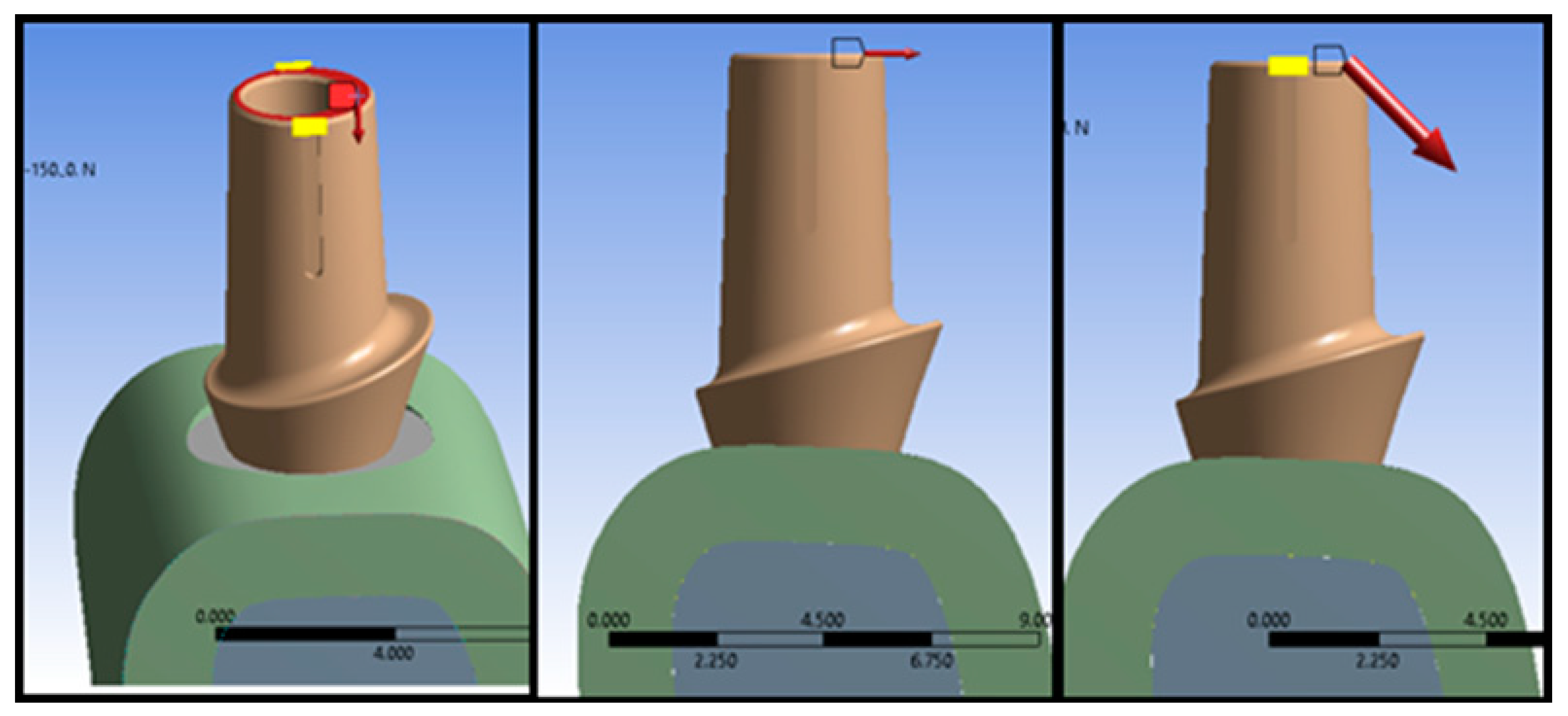
| Type of Loading | Magnitude of Load (N) | ||
|---|---|---|---|
| Vertical (V) | 50 | 100 | 150 |
| Horizontal (H) | 50 | 100 | 150 |
| Oblique (OB) | 70.711 | 141.42 | 212.13 |
| Name of Parts | PS I | PS II | PM | ||||
|---|---|---|---|---|---|---|---|
| Element Size (mm) | No. of Elements | No. of Nodes | No. of Elements | No. of Nodes | No. of Elements | No. of Nodes | |
| Abutment | 0.3 | 28,057 | 44,347 | 40,534 | 61,914 | 57,021 | 84,811 |
| Cancellous Bone | 0.4 | 208,907 | 293,542 | 208,907 | 293,542 | 208,907 | 293,542 |
| Cortical Bone | 0.4 | 131,591 | 193,133 | 131,591 | 193,133 | 131,591 | 196,133 |
| Implant | 0.3 | 47,805 | 71,857 | 47,805 | 71,857 | 47,805 | 71,857 |
| Screw | 0.2 | 17,472 | 26,282 | 17,472 | 26,282 | 17,472 | 26,282 |
| Total no. of elements and nodes | 433,832 | 629,161 | 46,309 | 646,728 | 762,796 | 669,625 | |
Disclaimer/Publisher’s Note: The statements, opinions and data contained in all publications are solely those of the individual author(s) and contributor(s) and not of MDPI and/or the editor(s). MDPI and/or the editor(s) disclaim responsibility for any injury to people or property resulting from any ideas, methods, instructions or products referred to in the content. |
© 2023 by the authors. Licensee MDPI, Basel, Switzerland. This article is an open access article distributed under the terms and conditions of the Creative Commons Attribution (CC BY) license (https://creativecommons.org/licenses/by/4.0/).
Share and Cite
Afazal, M.; Gupta, S.; Tevatia, A.; Afreen, S.; Chanda, A. Computational Investigation of Dental Implant Restoration Using Platform-Switched and -Matched Configurations. Computation 2023, 11, 79. https://doi.org/10.3390/computation11040079
Afazal M, Gupta S, Tevatia A, Afreen S, Chanda A. Computational Investigation of Dental Implant Restoration Using Platform-Switched and -Matched Configurations. Computation. 2023; 11(4):79. https://doi.org/10.3390/computation11040079
Chicago/Turabian StyleAfazal, Mohammad, Shubham Gupta, Abhishek Tevatia, Saba Afreen, and Arnab Chanda. 2023. "Computational Investigation of Dental Implant Restoration Using Platform-Switched and -Matched Configurations" Computation 11, no. 4: 79. https://doi.org/10.3390/computation11040079