Article

Influence of the Shape of Gear Wheel Bodies in Marine Engines on the Gearing Deformation and Meshing Stiffness

Faculty of Mechanical Engineering, Technical University of Košice, Letná 9, 042 00 Košice, Slovakia
*
Author to whom correspondence should be addressed.
J. Mar. Sci. Eng. 2021, 9(10), 1060; https://doi.org/10.3390/jmse9101060
Submission received: 24 August 2021 / Revised: 19 September 2021 / Accepted: 21 September 2021 / Published: 26 September 2021
(This article belongs to the Special Issue Marine Engines Performance and Emissions II)

Abstract

:
The basic properties of gears must be considered: the shape of their gearing, their load capacity, and the meshing stiffness, which affects the noise and vibration. When designing large gears, it is important to choose the correct shape of the gear body. Large gears used in marine gearboxes must be designed with as little weight as possible. The requirements of sufficient stiffness of the gear wheel body, as well as the meshing stiffness, must be met. This paper is devoted to the influence of spur gear wheel body parameters on gearing deformation and meshing stiffness. The stiffness of the gear is solved on the basis of the deformation of the gearing teeth, which is determined by the finite element method. Examples of the simulation and subsequent processing of results demonstrates how the individual parameters of the gear wheel body influence the stiffness of the gearing teeth. At the same time, the results point to designs of suitable shape and dimensions to achieve the required stiffness of the gearing teeth, but with the lowest possible weight of the spur gear wheel body.

1. Introduction

The development of modern machines and the means of production are characterized by ever-increasing performance parameters with a reduction in equipment weight. This way of designing transmission mechanisms is common in the shipbuilding industry [1]. Reducing the weight of the gears to a minimum leads to higher stress values in machine parts, causing the formation of various failures. During the operation of gears, malfunctions arise, which can be caused by the following: the bending fatigue of gear teeth, the formation and expansion of pittings, the wear of the gear teeth by abrasion, gear tooth seizure, and insufficient tooth stiffness. Another group of malfunctions are gear failures, which can be caused by the following: the insufficient quality of gear material, gear manufacturing technology, and gear heat treatment; incorrect gear manufacturing; improper lubrication and incorrect lubricant selection; a foreign body in the lubricant; the incorrect mounting of the gears, and the wrong design of the gears with regard to the transmitted power.
The gearbox is one of the most commonly used mechanical components, which is widely used in mechanical transmission equipment. Gearboxes are manufactured with weights ranging from 20 kg up to more than 20 tons. The weight of marine gearboxes is in the heavier section of this range and they are able to produce torque of up to 1,100,000 Nm. The range of applications as well as the range of torques is very broad. Unlike a vehicle gearbox, the vast majority of marine gearboxes do not switch between cogs because there is no clutch to disconnect the drive. The marine gears are always in mesh and usually always turning [2]. They are engaged by some form of clutch locking them to the shaft or a brake band stopping a drum containing gears from turning (so the gears are forced to turn).
During the design of the geometry of the gears one can prevent errors through a correct and thorough calculation of these gears. Modern developments bring more precise computational methods based on new theoretical and experimental research. These methods are expected to determine the dimensions of the gears so that the gears achieve a high operational reliability. These methods should prevent the gear teeth from breaking under a given load or deforming beyond the functional level.
Under a given load, the teeth of the co-engaging wheels deform and this causes the failure of the meshing. The deformation of a tooth is generally quantified by the amount of tooth stiffness, which is atidefined as the load to deformon ratio. When designing gear parameters, it is an important step to focus on achieving the desired tooth stiffness.
The transmission mechanism is an acoustically closed system from which noise is propagated mainly by vibrations of the box surface or connected units, including the base structure [3,4]. The most significant cause of noise is the so-called Transmission Error. This error is related to the kinematic accuracy and stiffness of the gear.
The vibrations from the gears transmitted to the gearbox housing are the most significant source of noise [5,6,7]. From a physical point of view, the cause of vibrations is a dynamic force that can change its amplitude, direction, or field of action. In the case of involute gearing, the most significant change is the amplitude, the main cause of which is the variable stiffness of gearing and shock at the entry of teeth into meshing due to deformations and deviations in the pitch and profile of the teeth, which are different from the theoretical pitch and profile.
Due to the complex shape of the teeth, the theoretical determination of the deformation and stiffness of the teeth is difficult to carry out. Nowadays, it is characterized by a rapidly evolving computational technique that for solving a wide performs extensive calculations, where various numerical methods to solve gear problems are encountered. One of these methods is the finite element method. It is one of the numerical methods of mathematics, widely used for solving problems of elasticity and strength, dynamics of flexible bodies and, at the same time, for investigating the deformation of gears, and thus the stiffness during meshing.
During the design of the large gears, which are used in marine machines, it is also necessary to consider the influence of the shape of the gear body. Such a body must meet the basic requirements of stiffness and strength with the lightest possible construction of the gear body. The shape and geometrical parameters of the gear bodies used in marine gearboxes depend on the method of manufacture of these large gears. Gear wheels for marine gearboxes can be manufactured as castings, forgings and sometimes as welded gear body structures.
Several studies are aimed at the suitable geometric optimization of the shape of the gear body. Wang, in his work aimed at volume reduction in gear wheels, using the Matlab simulation, achieved a total of 25.2% mass reduction and 11.42% power loss of the optimized transmission [8]. The optimization was carried out from solid structure gear bodies with a combination of web-type structures with cross-shaped-type structures; the biggest gear wheel was optimized to the H-shape gear wheel structure. Monkova et al. carried out a study on the change of natural frequencies in gear wheel reduction [9]. In this study four gear wheels were made: one had a solid body and the next three had a ribbed body with the same count of ribs but a different rib width. Modal analysis proved that natural frequencies increased more slowly at low natural modes than at high natural modes. Xu Jin et al.’s work was to design a ball mill gear wheel [10]. This wheel was designed to have a smaller radius than the original gear wheel. Yet, the body shape of the mill gear wheel was designed to be lightweight using a profiled web connected to an outer gearing ring with holes of thicker width for connection to the ball mill. Naveen et al. conducted a study aimed at the thin-walled structures of gear wheels [11]. For this experiment three gears were designed: one with a thick symmetrical web, one with a thin asymmetrical web, and one with a thin symmetrical web. The results of the study revealed with lowering the web and rim thickness, the strength of the structure decreases. Marunic performed an analysis of a thin asymmetric thin-rimmed gear [12]. The conclusion of this study was that the maximum stress was located at the rim and web joint. This stress was at a maximum for the thinnest rim regarding the web thickness. However, for the thicker rim, the maximum stress increased with a thinner web. Zhao et al. made a structural optimization of a double web herringbone gear [13]. This gear was optimized by adding a material to the existing web structures to tilt them slightly. The volume of this gear increased by 5.3%, but the maximal stress in the gear decreased by 11.9%.
This paper is dedicated to the analysis of the basic parameters for the body of the spur gear, and their influence on the deformation and stiffness of the gear in the mesh. The design issue for large spur gears used in marine gearboxes, for which the semi-finished product is a casting or forging, is described in this paper. The stiffness of the teeth is solved based on the deformation of the gearing, which is determined by the finite element method. Examples of simulations and the subsequent processing of results demonstrate the profound influence of the individual parameters of the gear body on the gearing stiffness. At the same time, the results point to suitable designs of shape and dimensions to achieve the required gearing stiffness, but with the lowest possible weight of the spur gears.

2. Materials and Methods

Gears have various design types. In accordance with the careful design of the gearing, it is necessary to address the issue of designing a suitable shape of the gear wheel body. In the case of gears used in marine gearboxes, which are of large dimensions, the gears are designed to be lightweight. In the case of the necessary choice of a lightened gear body, it is necessary to maintain the stiffness of the body itself, but also to remember and consider the necessary meshing stiffness.
This work is focused on large-dimension spur gears made with a relief. Such gears can be forged, cast, or welded. The shape of the gear body depends on several factors, such as the size of the wheel, the material, the method of manufacture, and the use of the gear.

2.1. Body Shape of Forged Spur Gears

Forged spur gears are mainly used for the production of semi-finished products for gears, which will later be developed into their final form. These semi-finished products are formed by operations such as open-die drop forging or impression-die drop forging. The gearing is forged with additional material wrapped around the tooth profile. Both ferrous and non-ferrous metals such as carbon steel, alloy steel, stainless steel, titanium, nickel, aluminum, and tool steel can be used to produce forged gears.
Figure 1 shows the shapes of forged spur gears. Figure 1a shows the shape of the gear body without relief holes. The use of relief holes reduces the weight of the wheel. If the gearing width is less than the wheel hub width, the shape shown in Figure 1c is used. The most commonly used shape of forged spur gears is shown in Figure 1b. Gears with a diameter d ≤ 150 to 200 mm are made of a solid bar semi-finished product by forging. Drop forging is used for spur gears with a diameter d = 160 to 200 mm. The design of the shape of the forged spur gear, together with the prescription of the basic characteristic dimensions of the wheel, such as the dimensions of the rim, arms and hub, are shown in Table 1.
For analyzing the influence of the body shape of the forged spur gear on the deformation and engagement stiffness, a gear with the number of teeth z = 71 and the normalized modulus value mn = 2.5 mm was chosen. The basic dimensions for the variants of the investigated spur gear bodies that were selected are given in Table 2. Variant A1 is designed according to the dimensions shown in Table 1 and Variant A2 is a full wheel shape without weight relief. A gear body with an increased web thickness was used in Variant A3 (f = 0.7b); with a rim of twice the thickness and a shape without relief holes in Variant A4; with a rim of three times the thickness and a shape without relief holes in Variant A5; and with a rim of half thickness (see Table 1) and a shape without relief holes in Variant A6.

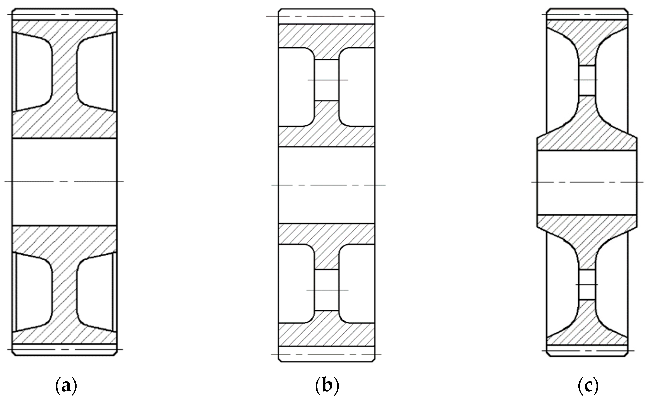
2.2. Construction of Cast Spur Gears

Casting is mostly used to create semi-finished products for large gear wheels. These gear wheels are less durable than forged wheels. The material used for these types of gear wheels is gray cast iron for a circumferential speed v < 7 m s−1 and cast steel for a circumferential speed v < 20 m s−1. For spur gear diameter d > 500 mm, the shape given in Table 3 is used.
Cast wheels can also be made with a full disc. For very large cast wheels, the connection of the hub to the rim is realized by means of arms with an elliptical, cross-sectional T-section (see Table 4). The arms must be checked with calculations for bending strength.
To analyze the influence of the body shape of the cast spur gear on the deformation and meshing stiffness, a gearing with the number of teeth z = 71 and the standardized modulus value mn = 7 mm, was chosen. The shapes of the investigated bodies of cast spur gears were designed, the basic dimensions for which are shown in Table 5. Variants of body shapes B1 and B2 are designed according to Table 3; a variants B3 and B4 are designed according to Table 5.
The work was created on a practical requirement basis to design the optimal shape of the body of the gear wheel with relief, i.e., gear wheels with the lowest possible weight, while maintaining the stiffness not only of the wheel body but also the stiffness and strength of the gear. The stiffness of the gearing is determined on the basis of the deformation of the gearing, whereas the deformation of the gearing is investigated by means of the finite element method.

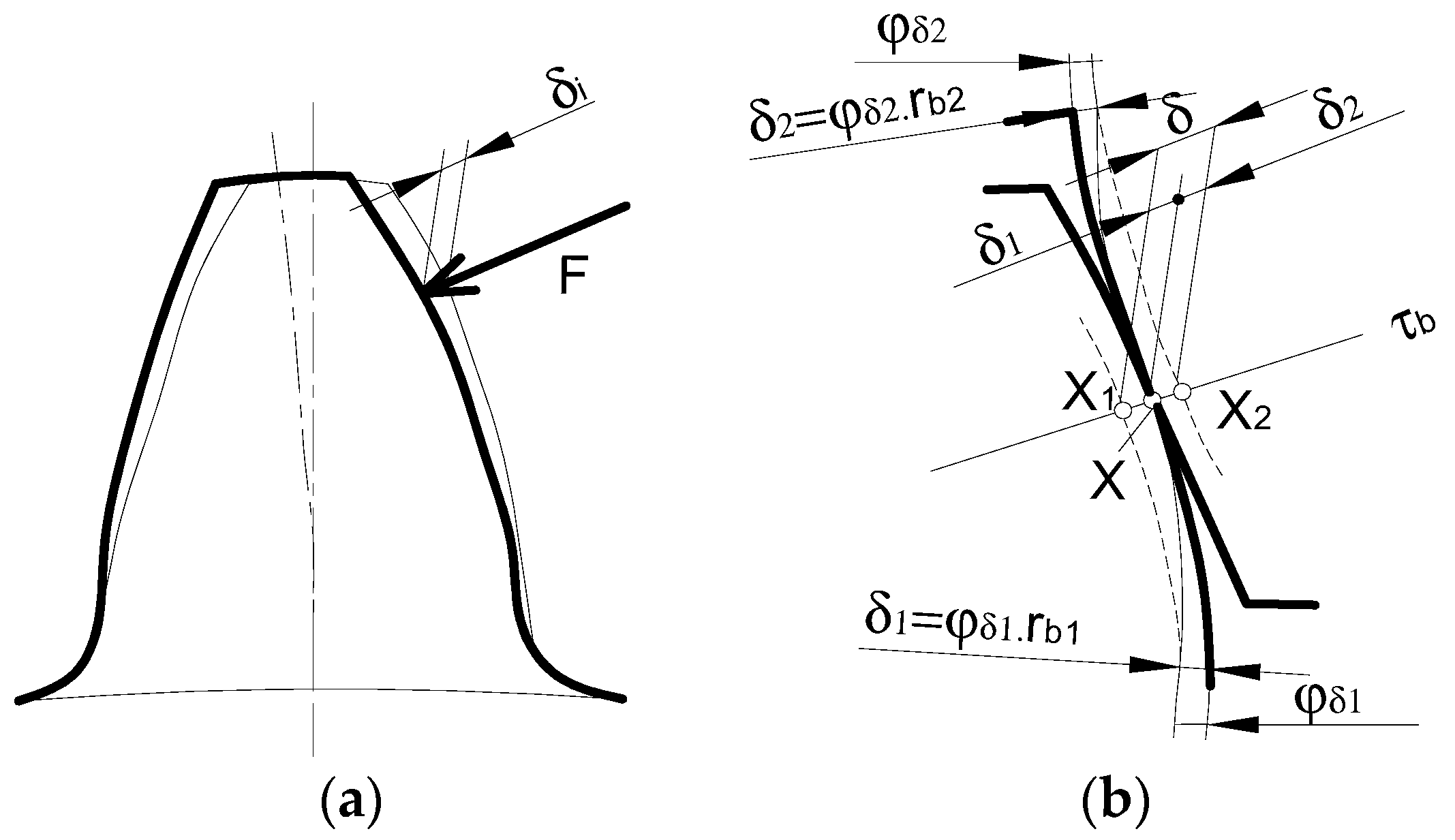
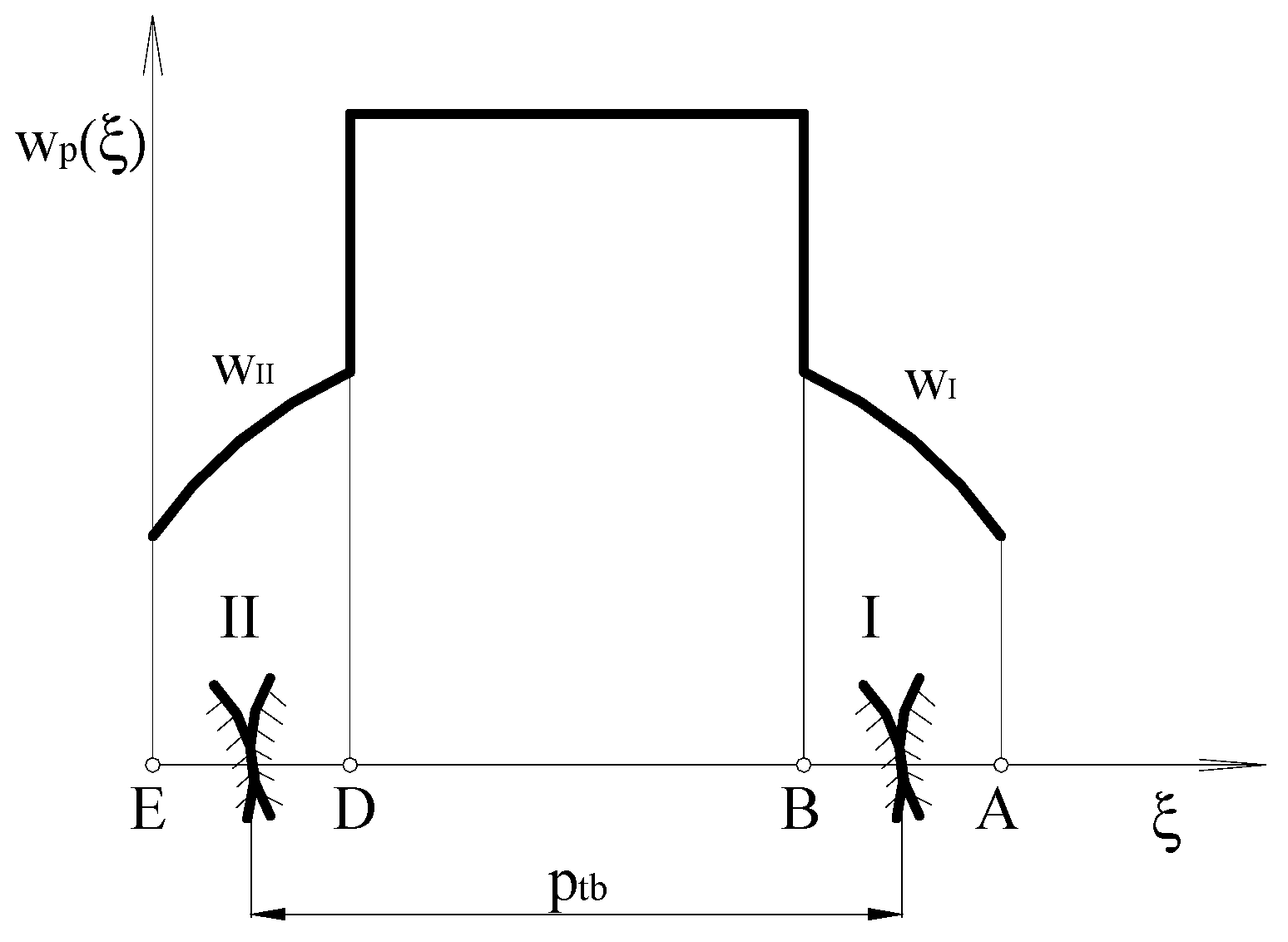
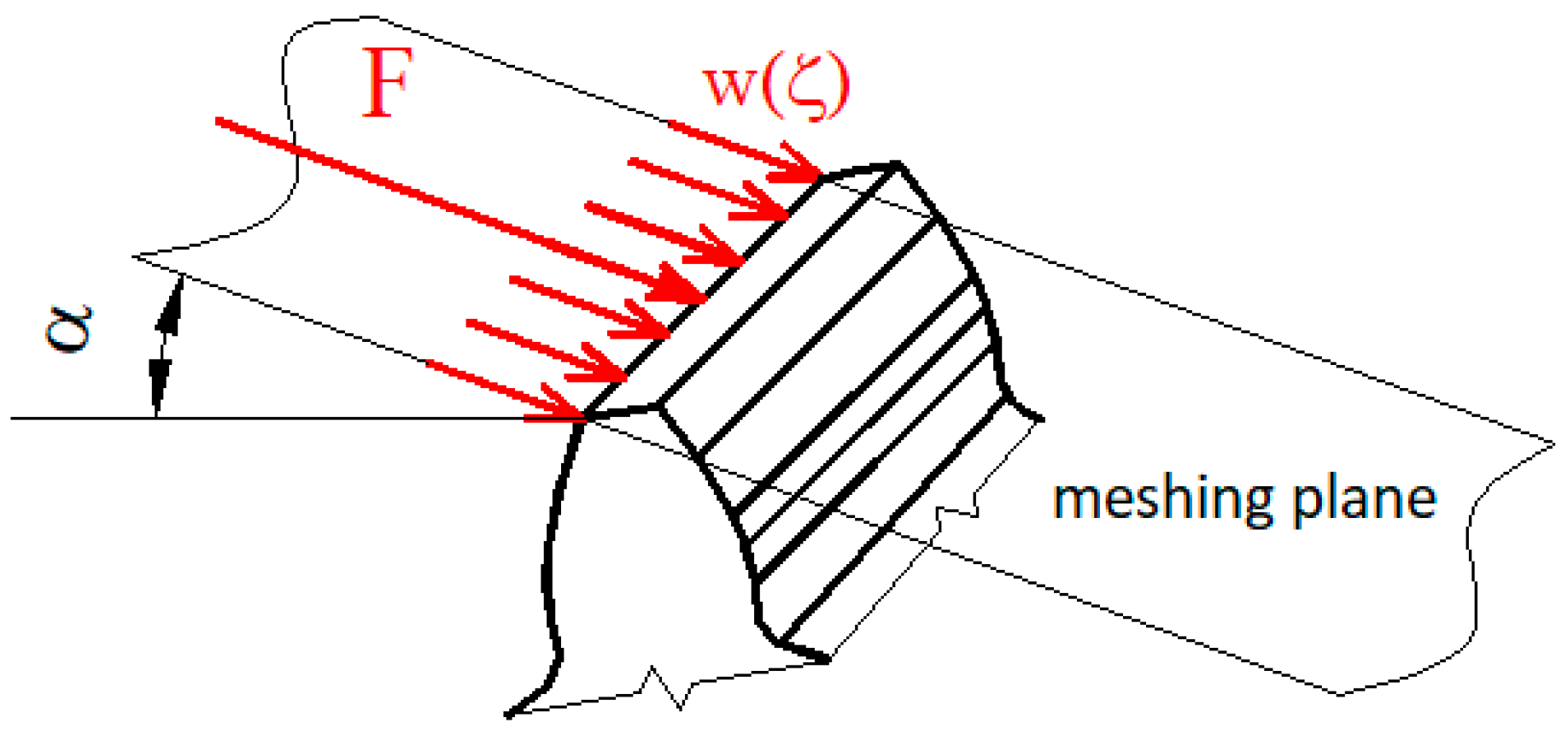
2.3. Gear Deformation and Meshing Stiffness

The teeth of the gears are deformed by the load. Under the action of the resulting normal force F, the tooth of one wheel is deformed, as illustrated by a thick line in Figure 2. The resulting deformation of the tooth in the direction of the normal force δi (i = 1,2—index, which distinguishes whether it is a pinion tooth, drive wheel or a driven wheel tooth) consists of a deformation from bending, shearing, the deformation at the point of entry and from tactile deformation [14].
However, in reality, it is necessary to determine the deformation of the interlocking teeth, i.e., the deformation of a pair of teeth, which can be imagined and illustrated in Figure 2b. This figure shows a section of a pair of teeth, which touch at the point X on a line of action τb in the unloaded state. After loading, the profiles of the two teeth engaging together deformed into the shape shown by the dashed line in the respective figure. These already deformed tooth profiles intersected the line of action at points X1 and X2. The total deformation of this pair of teeth δ could then be determined as the sum of the deformations of both teeth δ1 and δ2. There are the angles φδ1 and φδ2 shown in Figure 2. These are the angles by which the individual wheels must turn to meet again at point X, as is in fact the case.
The deformation is the same as the stiffness of the individual pairs of teeth and varies along the line of action [15,16]. A tooth has the greatest deformation when a force acts on the tip of the tooth, due to the large deformation of the tooth caused by bending [17]. To solve the common tasks of gear strength calculation, shaft calculation, and gear bearing, as well as in the case of the gear stiffness solution, the continuous load (wp) is replaced by isolated forces. The result of this continuous load is the force acting on the side of the tooth in the frontal plane. Because the gear ratio is greater than 1 for each gear, the resulting force acting on the tooth varies during the engagement depending on the number of tooth pairs engaging with each other. For precision spur gears with straight teeth, the load distribution between one and two pairs of teeth during the engagement is shown in Figure 3. In the two-pair engagement section (sections AB and DE), two pairs of teeth, I and II, are spaced apart by the basic pitch ptb, and the load of individual pairs is directly proportional to the stiffness of these pairs with regard to common deformation [18,19]. In the single-pair engagement section BD, the load is transmitted by one pair of teeth, where ξ is the coordinate of the line of action.
For the study of mesh stiffness, the distribution of the load on individual pairs of teeth meshing together is very important [20,21,22,23]. The stiffness of the individual teeth is examined, not the meshing stiffness. The maximum tooth deformation occurs when a load acts on the addendum of the tooth, i.e., at point A (see Figure 3). In this section, the load is divided between two meshing pairs of teeth. The deformation of the teeth was examined to observe if the load acted on the tooth addendum and split it between two meshing pairs of teeth that were simultaneously engaged.
Deformations of teeth are generally quantified by tooth stiffness, which is defined as the ratio of the load to the deformation. We define tooth stiffness as the force per unit of length that is required for a deformation by 1 μm. During the engagement cycle, the stiffness of the gearing changes is mainly due to a change in the bending arm.
Gear stiffness results are determined based on gear deformation. Gear deformation is determined by using the finite element method. The condition for the successful mastering of this issue is the creation of a computational model for solving the problems of static deformation analysis by the finite element method. The first step is to create geometric 3D models of individual gear wheels. The deformation of the teeth can also be examined on a model of the entire gear wheel or only on a suitable part of the gear wheel. The deformation was investigated on the model of the whole gear wheel.
The next step was to define the material properties of the gear wheels. The material from which the gear wheel was made was replaced in the study for solving FEM tasks, by using material constants which characterize the material. Basic material properties such as Young’s modulus of elasticity, the modulus of rigidity and Poisson’s number were used.
Due to the properties and use of the elements, a finite element of the SOLID type was used for the shape of the investigated three-dimensional geometric model of the gear wheel. This element was the shape of a prism. Due to the shape of the model, as well as the accuracy of the results, an 8-node version of this element with curved edges was chosen. The density of the mesh was defined by entering the number of elements on the control curves of the mesh entities. Based on the research, the finer mesh on the areas of the examined teeth was used to obtain the required accuracy of the results to finding this solution. The finer mesh was created by entering an appropriate number of finite elements on the individual control curves, given the size of the model. Here, it was necessary to follow the principle of creating the same number of elements on the curves forming the boundaries of neighboring entities.
In the mechanics of flexible bodies, we recognized two types of boundary conditions, geometric and force. Geometric boundary conditions defined the displacements on a part of the boundary of the examined body. In the place of rigid, inflexible bonds, the nodal displacements or rotations were zero. These were defined on the gear wheel hole. The force boundary conditions represented the prescribed surface forces at the body boundary. The action of the co-engaging teeth was replaced by a continuous constant load.
To verify the results of tooth deformation solved by the finite element method, tooth deformation was experimentally determined by the static measurement of tooth deformation at the point of load with a constant force [24,25,26,27,28,29,30,31,32].

3. Results and Discussion

The analysis of how the shape of the spur gear body influences the gear meshing stiffness is solved based on the results of the tooth deformation. In this work, the deformation of the gear is solved using the finite element method. To accomplish this, a computational model of the examined gear is created, which is the basis for solving the problems of static deformation analysis by the finite element method, using the program SolidWorks.
The load on the teeth of the spur involute gear has a continuous character. To solve the common tasks of gear strength calculation, shaft calculation, and gear bearing, the continuous load is replaced by a single force. Maximum deformations were investigated when the load acted on the tooth addendum (Figure 4).

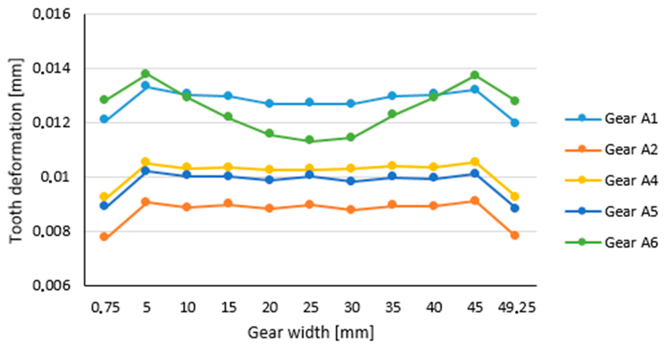
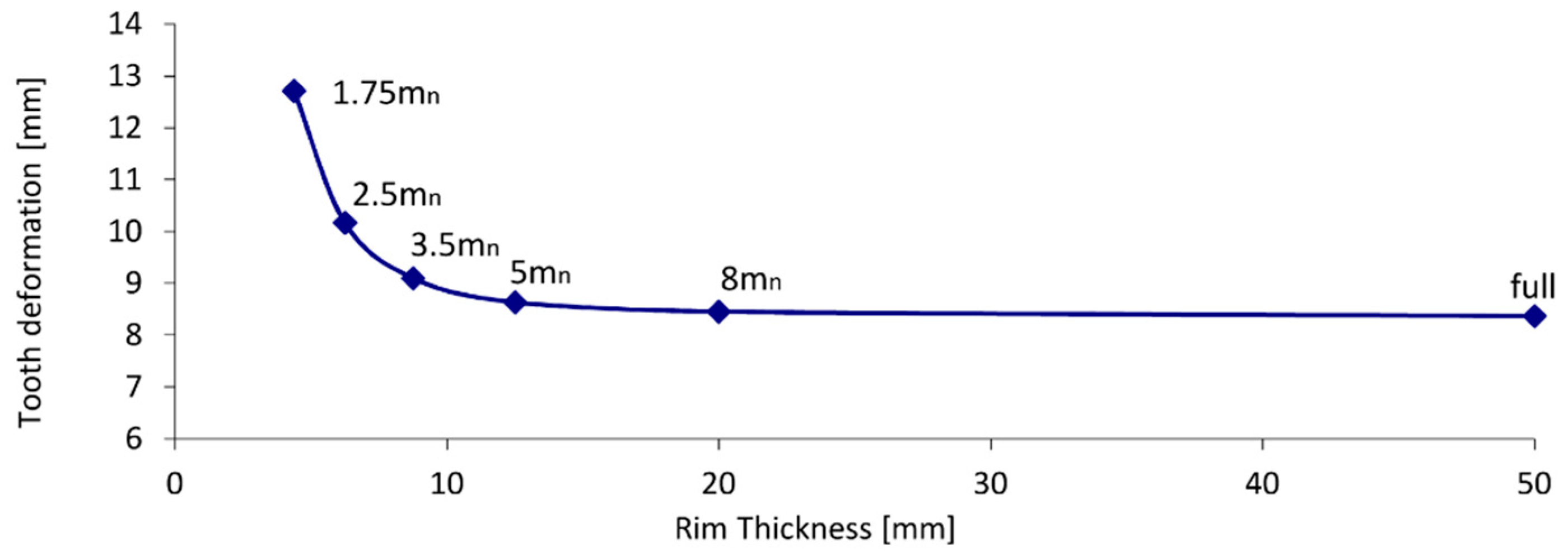
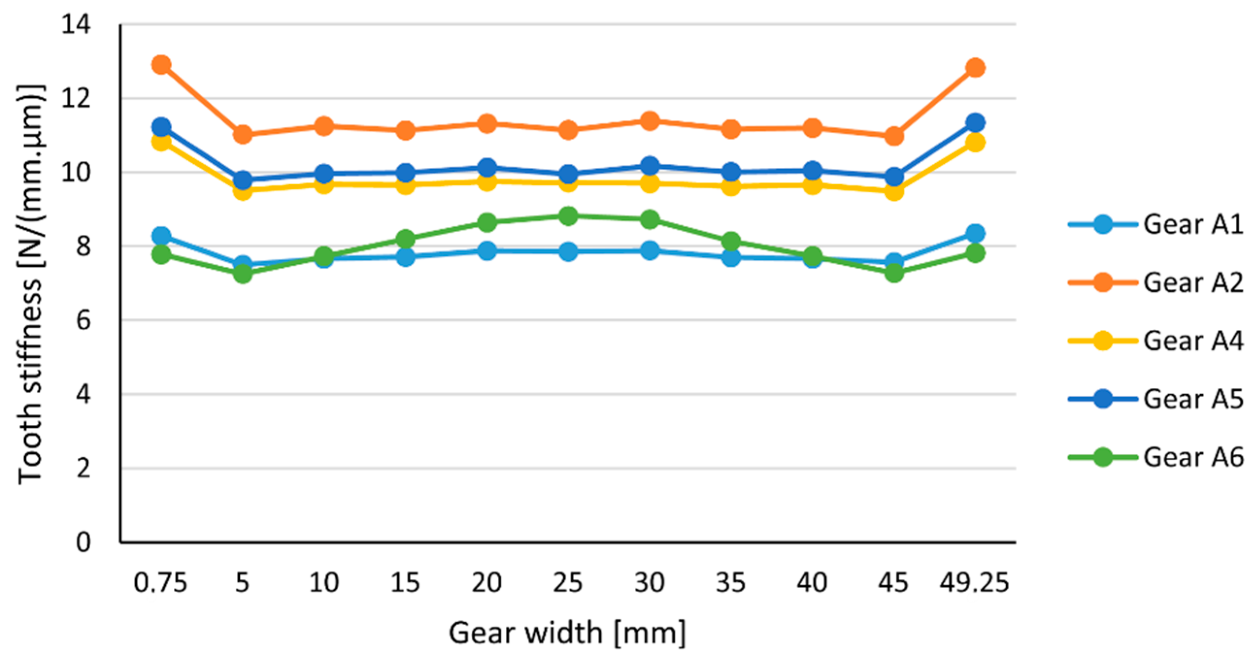
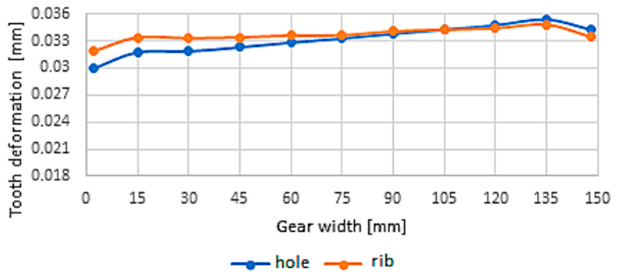
3.1. The Deformation and Gear Stiffness of Forged Gear Wheels

The gearing on the forged wheels was with the number of teeth z = 71 and the normalized value of the modulus, mn = 2.5 mm. The gear width was b = 50 mm and the problem was solved for spur gear wheels. The deformation was investigated for the wheel models listed in Table 2. The value of width load was w = 100 N/mm, expressed on the basis of a single force of F = 5000 N.
Figure 5 and Figure 6 shows the distribution of deformation across the width of the tooth when a load is applied to the addendum of the tooth for individual models of forged gear wheel shapes. As can be seen from the figure, the distribution of the deformation along the gear width was comparatively the same for all the examined shapes of the forged gear bodies. An exception is the A6 model (see Table 2), whose rim thickness is the smallest. For the model A6, the thickness of the rim is equal to 1.8 mn, which is much less than the permissible minimum thickness of the rim (3.5 mn). Therefore, the tooth deformation reflects the effect of a web with a thickness equal to f = 0.3 b = 15 mm located in the middle of the width of the wheel. At the location of the web, the deformation of the tooth decreased due to the supporting material of the web. The tooth deformation for model A1 was higher than for models A2 to A5, because the thickness of the rim was slightly greater than the minimum rim thickness defined by the standard value.
The deformation distribution along the width of the gear is also applied in Table 6.
In the next part, the influence of the rim thickness on the tooth deformation was investigated. Several spur gear models were created, where the web thickness was the same for all models (value of f = 15 mm) and the rim thicknesses varied (see Figure 5). Since the deformation along the tooth width was not constant beyond the deformation value that represented the tooth deformation, the deformation at the center of the tooth width was defined. Figure 7 shows the dependence of the tooth deformation on the thickness of the rim. As the results show, reducing the thickness of the rim increased the deformation of the teeth.
As can be seen from the acquired values, up to a rim size of 3.5 mn, the deformation changed by a large amount.
Figure 8 shows a comparison of the tooth stiffness over the width of the contact course for the individual shapes of the forged spur gears. The increase in stiffness (decrease in deformation) at the edges of the wheel was caused by a chamfer, i.e., a supporting effect. The gear wheel with a full body shape (variant A2) had the greatest stiffness. Variant A2 had the smallest deformation of the teeth, which was caused by the supporting effect of the material. Variant A5 was the model with the second smallest deformation of the teeth, and thus the species with the greatest stiffness of the teeth. The following are the A4 and A3 gears. There was very little difference between the values of tooth deformation (tooth stiffness) despite the different shapes of the bodies. The biggest difference in the stiffness distribution across the width had the smallest rim thickness for the forged body model (Variant A6).
Figure 9 shows the effect of the rim width on gear stiffness. As the thickness of the rim increased, the rigidity of the gearing also increased. The thickness of the rim was of a lesser value than the 3.5 mn and affected the stiffness of the gearing more significantly; therefore, it was appropriate to choose the thickness of the rim equal to or greater than this value. For the A6 model, the thickness of the rim was equal to 1.8 mn, which was much lower than the permissible minimum thickness of the rim (3.5 mn). Therefore, the stiffness of the tooth reflected the effect of a web of size f = 0.3 mn = 15 mm located in the middle of the wheel width. At the location of the web, the stiffness of the tooth increased due to the supporting material of the web, unlike other models, where the thickness of the rim is greater than the allowed minimum.
A comparison of the effect of material reduction on gear deformation is shown in Figure 10. The greater the mass reduction, then the greater the final gear deformation. By comparing the effect of the percentage reduction in mass on the deformation of the gearing, the forged wheels marked A3 and A4 appear to be the most suitable variants (Table 2). These wheels have very similar gear deformations and mass reductions, while they differ in shape from each other. The A4 variant appears to be more advantageous from the point of view of the economy than the A3 variant, which has a more complicated shape for production and requires an additional machining process by drilling relief holes.

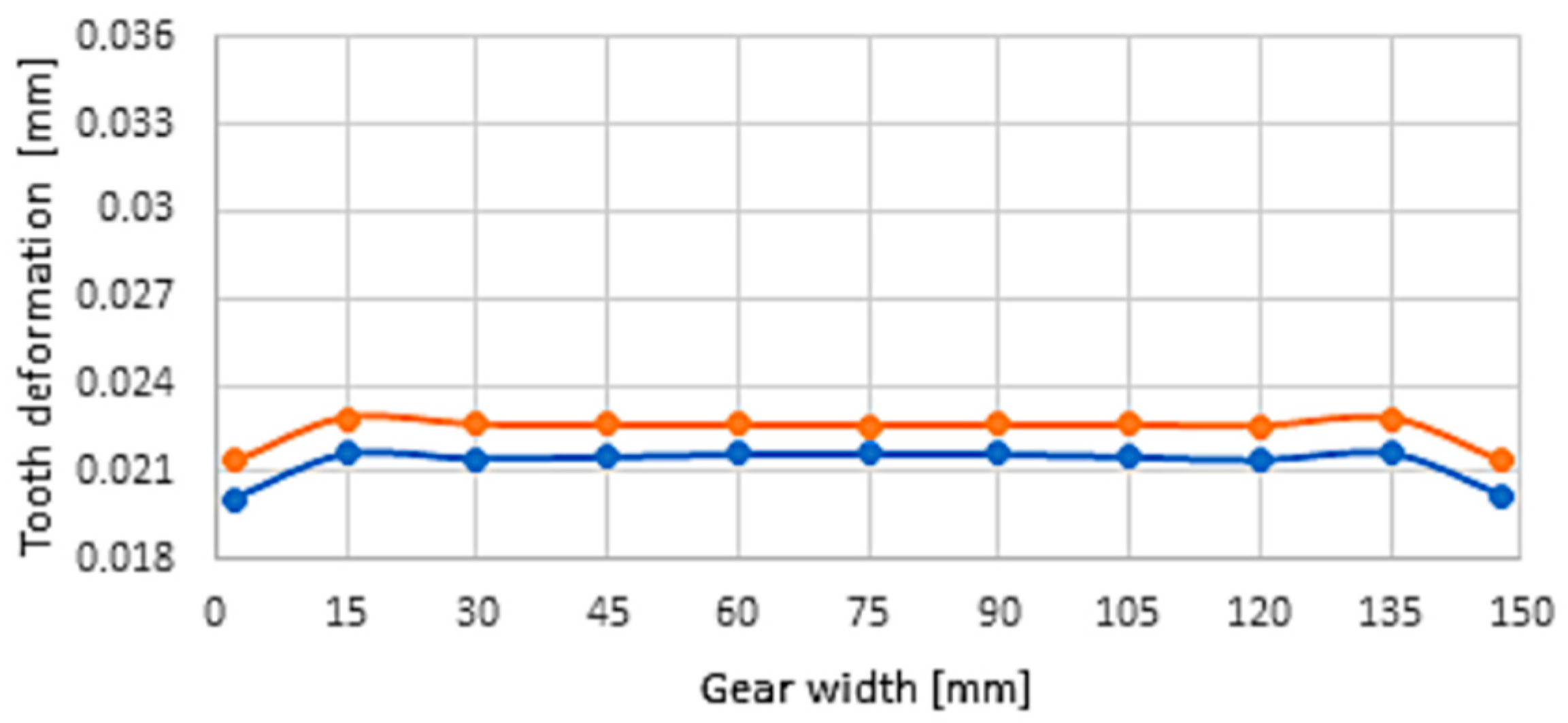
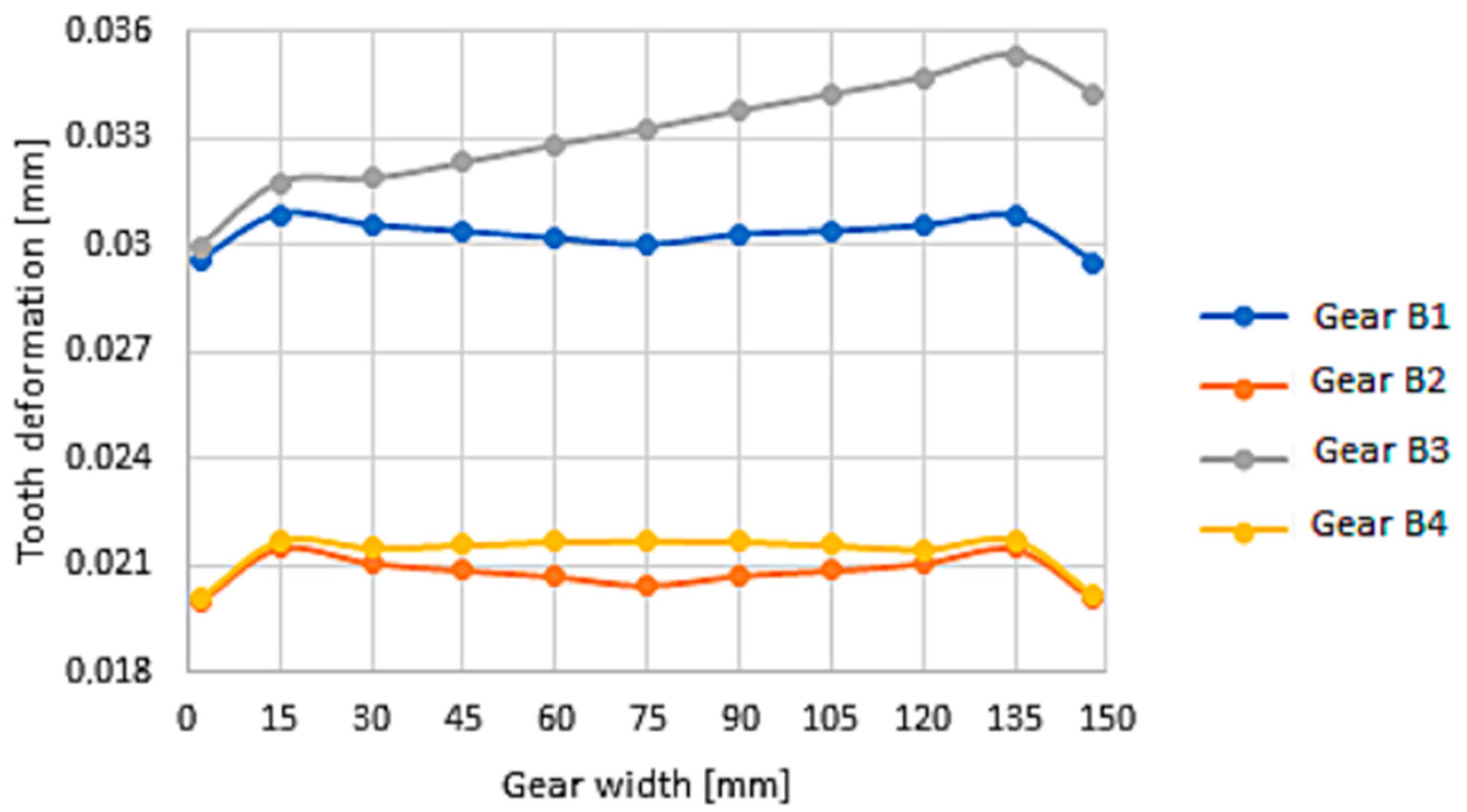
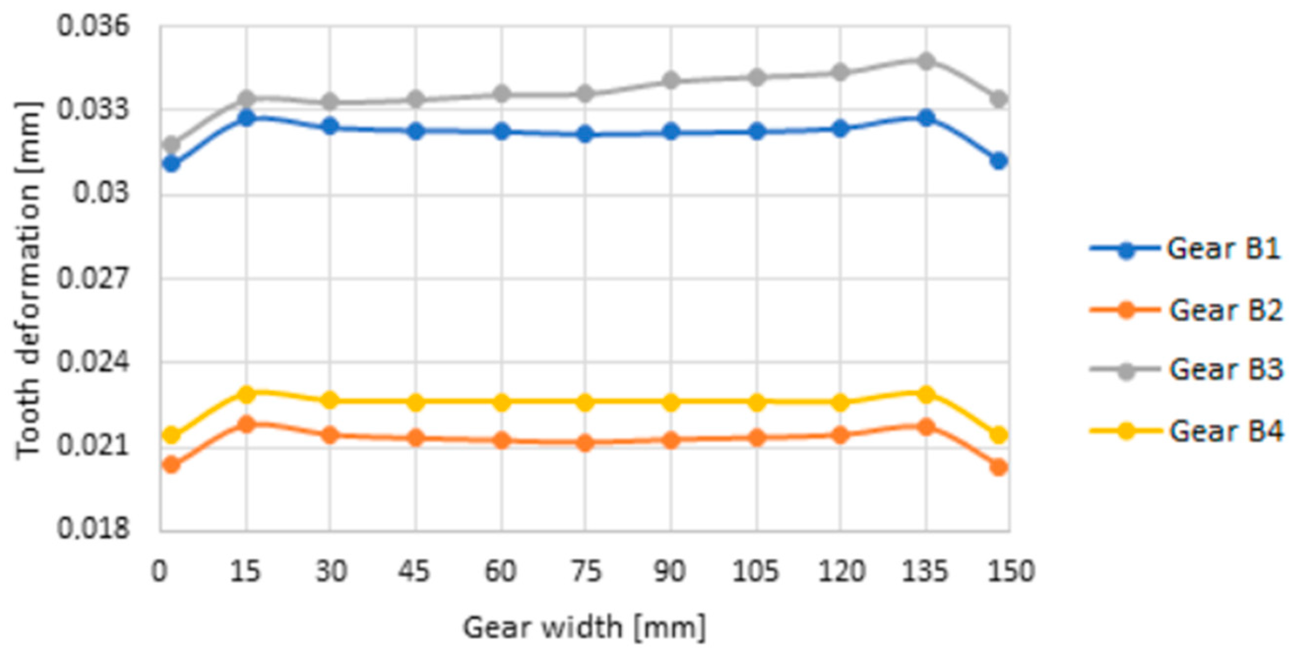
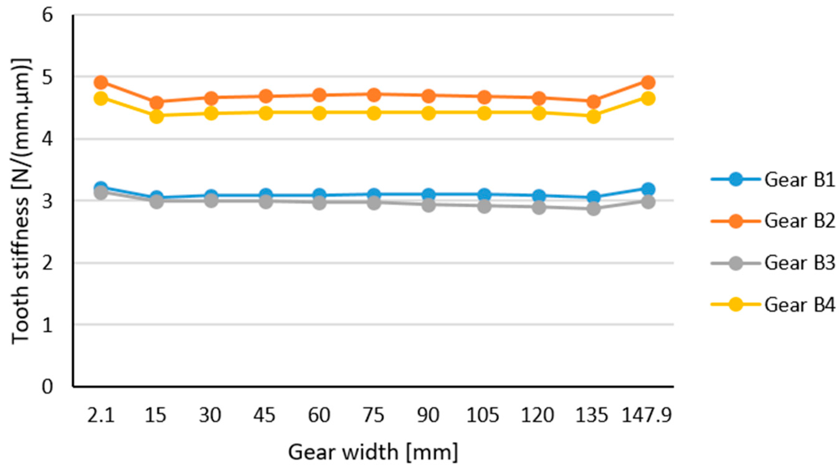
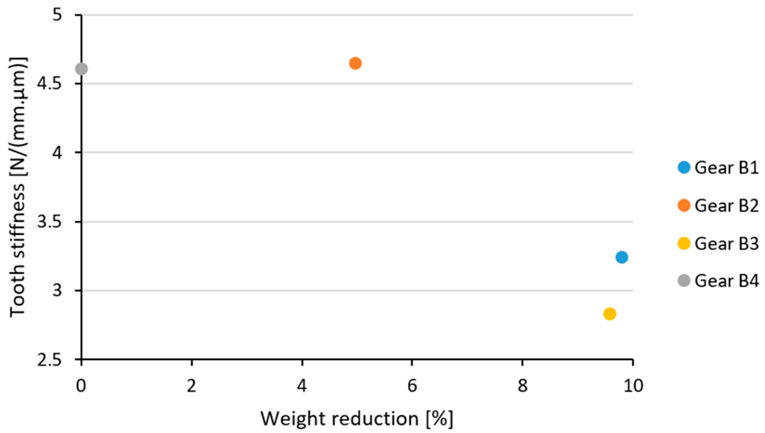
3.2. Deformation and Stiffness of Gearing of Cast Gears

The gearing of the cast gear wheels had the number of teeth z = 71, the normalized value of the modulus mn = 7 mm, and a gear width of b = 150 mm. The problem was solved for spur gear wheels. The deformation was investigated for the wheel models listed in Table 5. The magnitude of the width load, w = 100 N/mm, was expressed on the basis of a single force, F = 15,000 N.
The first step was to investigate the distribution of deformation along the wheel width where it was found that the deformation of the gearing was unequal; the teeth of the wheel that were located above the rib had less deformation than the teeth that were located above the holes (see Figure 11, Figure 12, Figure 13 and Figure 14). The smallest difference was found on model B2.
A mutual comparison of the deformation along the width of the tooth for models of cast spur gears is shown in Figure 15 if the tooth is placed above the hole, and in Figure 16 if the tooth is placed above the rib.
Figure 17 shows the stiffness of the casted gear wheel teeth which are located above the rib. The deviation of the course of deformation, as well as the stiffness of the gearing examined along the width of the gear wheel was smaller for the teeth located above the rib due to the supporting stiffness effect of the rib.
Figure 18 is a comparison of the effect of weight loss on gear stiffness for cast spur gears. Wheel B4 was chosen as a wheel with zero mass loss, because its weight was the largest of the proposed models. However, the B4 wheel weighed 50.5% less than a full solid-body gear wheel. From Figure 18 it was determined that the gearing stiffness decreased with an increase in material loss. The exception was the B3 wheel due to its shape. Gear wheels B1 and B3 had the highest mass reduction, but their gear stiffnesses were smaller compared to wheels B2 and B4. The wheels B2 and B4 had almost the same amount of gear stiffness, but the wheel B2 had a greater mass reduction, which was more advantageous in terms of weight. Due to its having the highest gear stiffness and a relatively good weight, wheel B2 is the most advantageous.

4. Conclusions

One factor in assessing the appropriate shape of a large cast spur gear wheel is to assess its suitability for deformation and the stiffness of the teeth. The steady increase in the performance factors and the decrease in the weight of the device are achieved via the development of the modern machinery and means of production. The lightening of the gear wheel body affects the deformation and stiffness of the teeth. Based on these results, it can be concluded that the fewer shape modifications made to the gear wheel body, the smaller the teeth deformation of the gear wheel.
As the thickness of the rim increases, the deformation of teeth decreases, and thus the stiffness of the teeth increases. A thickness of the rim of less than 3.5 mn affects the deformation of the teeth and the stiffness of the gearing more significantly. Therefore, it is advisable to choose a wreath thickness that is greater than 3.5 mn. The normalized module value for spur gears has the symbol mn.
As the width of the web, which is located in the center of the width of the gear wheel, increases, the deformation of the gear teeth decreases slightly and the stiffness of the teeth increases slightly. The location of the web also affects the meshing stiffness of the gears, as do the various relief holes located in the web.
In gear design, gear noise is also a major concern. The main source of gear noise is the appearance of non-uniform rotations of the gear wheels. Periodic changes in the stiffness of the teeth during meshing in the gear are the main effects of the noise in the transfer. Reducing the dynamic loading and noise of gear systems is an important concern in gear design. When designing cast and forged gears, i.e., gears of large dimensions, it is important to assess the appropriate choice of body shape which also considers the meshing stiffness of the gearing.

Author Contributions

Conceptualization, S.M.; methodology, S.M. and M.P.; investigation, S.M.; data analysis, S.M. and S.S.; writing—original draft preparation, S.M.; writing—review and editing, M.P., S.S., P.F. and D.H. All authors have read and agreed to the published version of the manuscript.

Funding

This research is a part of these projects KEGA 029TUKE-4/2021, KEGA 027TUKE-4/2020, VEGA 1/0290/18. This work was supported by the Slovak Research and Development Agency under the Contract no. APVV-19-0328.

Institutional Review Board Statement

Not applicable.

Informed Consent Statement

Not applicable.

Data Availability Statement

The data presented in this study are part of the authors’ research.

Conflicts of Interest

The authors declare no conflict of interest.

References

  1. Kumar, S.M.; Govindaraj, E.; Balamurugan, D.; Daniel, F. Design analysis and fabrication of automotive transmission gearbox using hollow gears for weight reduction. Mater. Today Proc. 2021, 45, 6822–6832. [Google Scholar] [CrossRef]
  2. Stroh, J.; Sediako, D. Residual Stress Characterization for Marine Gear Cases in As-Cast and T5 Heat Treated Conditions with Application of Neutron Diffraction. Light Met. 2019, 2019, 395–399. [Google Scholar]
  3. Henriksson, M. Analysis of gear noise and dynamic transmission error measurements. ASME Int. Mech. Eng. Congr. Expo. 2004, 47020, 229–237. [Google Scholar]
  4. Park, S.; Kim, S.; Choi, J.H. Gear fault diagnosis using transmission error and ensemble empirical mode decomposition. Mech. Syst. Signal Process. 2018, 10, 262–275. [Google Scholar] [CrossRef]
  5. Dong, J.W.; Pei, W.C.; Long, H.Y.; Chu, J.; Ji, H.C. Solution of spur gear meshing stiffness and analysis of degradation characteristics. Mechanika 2020, 26, 153–160. [Google Scholar]
  6. Malakova, S.; Puskar, M.; Frankovsky, P.; Sivak, S.; Palko, M.; Palko, M. Meshing Stiffness—A Parameter Affecting the Emission of Gearboxes. Appl. Sci. 2020, 10, 8678. [Google Scholar] [CrossRef]
  7. Jakubovičová, L.; Ftorek, B.; Baniari, V.; Sapietová, A.; Potoček, T.; Vaško, M. Engineering Design of a Test Device. Procedia Eng. 2017, 177, 520–525. [Google Scholar] [CrossRef]
  8. Wang, C. High power density design for planetary gear transmission system. Proc. Inst. Mech. Eng. Part C J. Mech. Eng. Sci. 2019, 233, 5647–5658. [Google Scholar] [CrossRef]
  9. Monkova, K.; Monka, P.; Tkac, J.; Hricova, R.; Mandulak, D. Effect of the Weight reduction of a Gear Wheel on Modal Characteristics. MATEC Web Conf. 2019, 299, 1–6. [Google Scholar] [CrossRef] [Green Version]
  10. Xu, J.; Wang, C.X. Small Module Design of Ball Mill Main Drive Gear with Φ2.4 × 10m. Adv. Mater. Res. 2013, 787, 490–494. [Google Scholar] [CrossRef]
  11. Marunić, G. Rim Stress Analysis of Thin-Rimmed Gear. Key Eng. Mater. 2007, 348–349, 141–144. [Google Scholar] [CrossRef]
  12. Naveen, P.N.E.; Sujith Kumar, B.; Goriparthi, B.K.; Hota, R.S.; Chaitanya Mayee, M.; Gopala Raju, S.S.S.V. Design and analysis of thin wall gear structure with Tio2/GF reinforced Nylon66 composites. Mater. Today Proc. 2021, 46, 382–389. [Google Scholar] [CrossRef]
  13. Zhao, N.; Sun, L.L.; Fu, B.B.; Li, H.F.; Wang, Q.B. Web Structural Optimization of the Big Aviation Herringbone Gear Based on APDL Language. Appl. Mech. Mater. 2014, 487, 692–698. [Google Scholar] [CrossRef]
  14. Medvecká-Beňová, S. Influence of the face width and length of contact on teeth deformation and stiffness. Sci. J. Sil. Univ. Technol. Ser. Transp. 2016, 91, 99–106. [Google Scholar] [CrossRef]
  15. Patel, A.; Shakya, P. Spur gear crack modelling and analysis under variable speed conditions using variational mode decomposition. Mech. Mach. Theory 2021, 164, 104357. [Google Scholar] [CrossRef]
  16. Pleguezuelos, M.; Sánchez, M.B.; Pedrero, J.I. Analytical model for meshing stiffness, load sharing, and transmission error for spur gears with profile modification under non-nominal load conditions. Appl. Math. Model. 2021, 97, 344–365. [Google Scholar] [CrossRef]
  17. Flek, J.; Dub, M.; Kolar, J.; Lopot, F.; Petr, K. Determination of Mesh Stiffness of Gear—Analytical Approach vs. FEM Analysis. Appl. Sci. 2021, 11, 4960. [Google Scholar] [CrossRef]
  18. Xiong, Y.S.; Huang, K.; Xu, F.W.; Yi, Y.; Sang, M.; Zhai, H. Research on the Influence of Backlash on Mesh Stiffness and the Nonlinear Dynamics of Spur Gears. Appl. Sci. 2019, 9, 1029. [Google Scholar] [CrossRef] [Green Version]
  19. Gkimisis, L.; Vasileiou, G.; Sakaridis, E.; Spitas, C.; Spitas, V. A fast, non-implicit SDOF model for spur gear dynamics. Mech. Mach. Theory 2021, 160, 104279. [Google Scholar] [CrossRef]
  20. Marques, P.M.T.; Marafona, J.D.M.; Martins, R.C.; Seabra, J.H.O. A continuous analytical solution for the load sharing and friction torque of involute spur and helical gears considering a non-uniform line stiffness and line load. Mech. Mach. Theory 2021, 161, 104320. [Google Scholar] [CrossRef]
  21. Shen, J.; Hu, N.Q.; Zhang, L.; Luo, P. Dynamic Analysis of Planetary Gear with Root Crack in Sun Gear Based on Improved Time-Varying Mesh Stiffness. Appl. Sci. 2020, 10, 8379. [Google Scholar] [CrossRef]
  22. Císar, M.; Kuric, I.; Čuboňová, N.; Kandera, M. Design of the clamping system for the CNC machine tool. MATEC Web Conf. 2017, 137, 01003. Available online: https://www.researchgate.net/publication/321215438_Design_of_the_clamping_system_for_the_CNC_machine_tool (accessed on 20 September 2021). [CrossRef] [Green Version]
  23. Hudak, R.; Polacek, I.; Klein, P.; Sabol, R.; Varga, R.; Zivcak, J.; Vazquez, M. Nanocrystalline Magnetic Glass-Coated Microwires Using the Effect of Superparamagnetism Are Usable as Temperature Sensors in Biomedical Applications. IEEE Trans. Magn. 2017, 53, 1–5. Available online: https://ieeexplore.ieee.org/abstract/document/7814333 (accessed on 20 September 2021). [CrossRef]
  24. Jiang, H.; Sitoci-Ficici, K.; Reinshagen, C.; Molcanyi, M.; Zivcak, J.; Hudak, R.; Laube, T.; Schnabelrauch, M.; Weisser, J.; Schäfer, U.; et al. Adjustable Polyurethane Foam as Filling Material for a Novel Spondyloplasty: Biomechanics and Biocompatibility. World Neurosurg. 2018, 112, e848–e858. Available online: https://www.sciencedirect.com/science/article/abs/pii/S1878875018302171 (accessed on 20 September 2021). [CrossRef]
  25. Koutecký, T.; Zikmund, T.; Glittová, D.; Paloušek, D.; Živčák, J.; Kaiser, J. X-ray micro-CT measurement of large parts at very low temperature. Rev. Sci. Instrum. 2017, 88, 033707. Available online: https://aip.scitation.org/doi/abs/10.1063/1.4979077 (accessed on 20 September 2021). [CrossRef]
  26. Murčinková, Z.; Živčák, J.; Zajac, J. Experimental study of parameters influencing the damping of particulate, fibre-reinforced, hybrid, and sandwich composites. Int. J. Mater. Res. 2020, 111, 688–697. Available online: https://www.degruyter.com/document/doi/10.3139/146.111933/pdf (accessed on 20 September 2021). [CrossRef]
  27. Pistek, V.; Klimes, L.; Mauder, T.; Kucera, P. Optimal design of structure in rheological models: An automotive application to dampers with high viscosity silicone fluids. J. Vibroengineering 2017, 19, 4459–4470. Available online: https://www.jvejournals.com/article/18348 (accessed on 20 September 2021). [CrossRef]
  28. Puškár, M.; Jahnátek, A.; Kuric, I.; Kádárová, J.; Kopas, M.; Šoltésová, M. Complex analysis focused on influence of biodiesel and its mixture on regulated and unregulated emissions of motor vehicles with the aim to protect air quality and environment. Air Qual. Atmos. Health 2019, 12, 855–864. Available online: https://link.springer.com/article/10.1007/s11869-019-00704-w (accessed on 20 September 2021). [CrossRef]
  29. Píštěk, V.; Kučera, P.; Fomin, O.; Lovska, A. Effective Mistuning Identification Method of Integrated Bladed Discs of Marine Engine Turbochargers. J. Mar. Sci. Eng. 2020, 8, 379. Available online: https://www.mdpi.com/2077-1312/8/5/379 (accessed on 20 September 2021).
  30. Sabol, R.; Klein, P.; Ryba, T.; Hvizdos, L.; Varga, R.; Rovnak, M.; Sulla, I.; Mudronova, D.; Galik, J.; Polacek, I.; et al. Novel Applications of Bistable Magnetic Microwires. Acta Phys. Pol. A 2017, 131, 1150–1152. [Google Scholar] [CrossRef]
  31. Sága, M.; Bulej, V.; Čuboňova, N.; Kuric, I.; Virgala, I.; Eberth, M. Case study: Performance analysis and development of robotized screwing application with integrated vision sensing system for automotive industry. Int. J. Adv. Robot. Syst. 2020, 17, 172988142092399. Available online: https://xueshu.baidu.com/usercenter/paper/show?paperid=184m0r70kg0f0a00bs7s0vq0g8225814&site=xueshu_se&hitarticle=1 (accessed on 20 September 2021). [CrossRef]
  32. Toth, T.; Hudak, R.; Zivcak, J. Dimensional verification and quality control of implants produced by additive manufacturing. Qual. Innov. Prosper. 2015, 19, 9–21. Available online: https://www.qip-journal.eu/index.php/QIP/article/view/393 (accessed on 20 September 2021). [CrossRef] [Green Version]
Figure 1. Body shapes of forged spur gears: (a) shape without relief holes; (b) the most commonly used shape of forged spur gears; (c) shape with openings for weight reduction.
Jmse 09 01060 g001
Figure 2. Deformation of (a) tooth, (b) teeth meshing deformation.
Jmse 09 01060 g002
Figure 3. Load of individual pairs of teeth of precise straight spur gearing (sections AB and DE are two engaging gear pairs of teeth; section BD is one engaging gear pair of teeth).
Jmse 09 01060 g003
Figure 4. Expression of continuous load by single force.
Jmse 09 01060 g004
Figure 5. Active gear width during engagement of the wheels.
Jmse 09 01060 g005
Figure 6. Comparison of tooth deformation along the width of the forged gear wheel for individual models.
Jmse 09 01060 g006
Figure 7. Influence of rim thickness on gear deformation.
Jmse 09 01060 g007
Figure 8. Comparison of gear stiffness across width for forged spur gears.
Jmse 09 01060 g008
Figure 9. Influence of rim thickness on gear stiffness.
Jmse 09 01060 g009
Figure 10. Influence of material reduction on maximum gear deformation.
Jmse 09 01060 g010
Figure 11. Deformation along the width of the tooth for model B1.
Jmse 09 01060 g011
Figure 12. Deformation along the width of the tooth for model B2.
Jmse 09 01060 g012
Figure 13. Deformation along the width of the tooth for model B3.
Jmse 09 01060 g013
Figure 14. Deformation along the width of the tooth for model B4.
Jmse 09 01060 g014
Figure 15. The deformation along the width of the tooth of the cast gear wheel located above the hole.
Jmse 09 01060 g015
Figure 16. The deformation along the width of the tooth of the cast gear wheel located above the rib.
Jmse 09 01060 g016
Figure 17. The stiffness along the width of the tooth of the cast gear wheel located above the hole.
Jmse 09 01060 g017
Figure 18. Influence of material loss on maximum gear stiffness for cast spur gears.
Jmse 09 01060 g018
Table 1. Forged spur gear—basic geometric parameters.
Forged Spur GearGear Parameters
Jmse 09 01060 i001
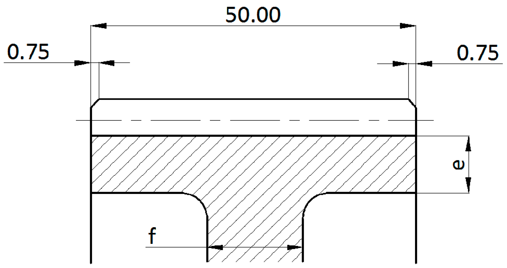
mn—modulus [mm]
h—height of key [mm]
b—width of gear wheel [mm]
dh—diameter of the hole for the shaft [mm]
g—calculated using parameters e, c, dh and df (root diameter)
chamfer s = 0.3 mn
e = (3 to 4) mn
c = (1.2 to 1.8 )h
do = (0.4 to 0.7) g
f = 0.3b
i = (0.4 to 0.7) do
L = (1.0 to 1.25) b
bs = 0.3 mn
Table 2. Variants of forged spur gears.
VariantWheel Size3D Model
A1 Jmse 09 01060 i002 Jmse 09 01060 i003
A2 Jmse 09 01060 i004 Jmse 09 01060 i005
A3 Jmse 09 01060 i006 Jmse 09 01060 i007
A4 Jmse 09 01060 i008 Jmse 09 01060 i009
A5 Jmse 09 01060 i010 Jmse 09 01060 i011
A6 Jmse 09 01060 i012 Jmse 09 01060 i013
Table 3. Cast medium-sized spur gear: basic geometric parameters.
Cast Medium-Sized Gear WheelWheel Parameters
Jmse 09 01060 i014mn—modulus [mm]
h—height of key [mm]
b—width of wheel [mm]
e = (4 to 5) mn
c = (1.8 to 2.2) h
f = (0.2 to 0.3) b
do = (0.6 to 0.7) g
k = (0.4 to 0.6) f
p = (0.2 to 0.5) k
s = 0.3 mn
L = (1.0 to 1.25) b
Table 4. Large casted spur gear—basic geometric parameters.
Large Casted Spur GearWheel Parameters
Jmse 09 01060 i015mn—modulus [mm]
h—height of key [mm]
b—width of wheel [mm]
dh—diameter of the hole for the shaft [mm]
e = (1.6 to 2.0) mn
g = 2.0 mn
f = (1.4 to 1.7) mn
k = (1.1 to 1.3) mn
L = (1.0 to 1.25) dh
l1= 0.5 dh
H = (8.0 to 10.0) mn
h = (6.0 to 8.0) mn
l1= 0.5 dh
i R = d / 7  1
c = 0.4dh + (5 to 10 [mm])
1 d—diameter of the pitch circle [mm], iR—number of arms, selected from 3 to 8.
Table 5. Variants of cast spur gears.
VariantWheel Size3D Model
B1 Jmse 09 01060 i016 Jmse 09 01060 i017
B2 Jmse 09 01060 i018 Jmse 09 01060 i019
B3 Jmse 09 01060 i020 Jmse 09 01060 i021
B4 Jmse 09 01060 i022 Jmse 09 01060 i023
Table 6. Gear deformations at the load point for the designed models of forged wheels.
Variant3D ModelMaximum Deformation [mm]Illustration of DeformationCut Section
A1 Jmse 09 01060 i024 Jmse 09 01060 i025 Jmse 09 01060 i026 Jmse 09 01060 i027
A2 Jmse 09 01060 i028 Jmse 09 01060 i029 Jmse 09 01060 i030 Jmse 09 01060 i031
A3 Jmse 09 01060 i032 Jmse 09 01060 i033 Jmse 09 01060 i034 Jmse 09 01060 i035
A4 Jmse 09 01060 i036 Jmse 09 01060 i037 Jmse 09 01060 i038 Jmse 09 01060 i039
A5 Jmse 09 01060 i040 Jmse 09 01060 i041 Jmse 09 01060 i042 Jmse 09 01060 i043
A6 Jmse 09 01060 i044 Jmse 09 01060 i045 Jmse 09 01060 i046 Jmse 09 01060 i047
Publisher’s Note: MDPI stays neutral with regard to jurisdictional claims in published maps and institutional affiliations.

