
Optimization of Process Parameters in Friction Stir Welding of Aluminum 5451 in Marine Applications
 , , ,
, , ,
Abstract
:1. Introduction
2. Materials and Methods
3. Results and Discussion
3.1. Process Parameters Optimization for the Tensile Strength and Hardness
3.2. Results Using Analysis of Variance
3.3. Response Optimization for Tensile Strength and Hardness
3.4. Joint Efficiency at Optimum Level
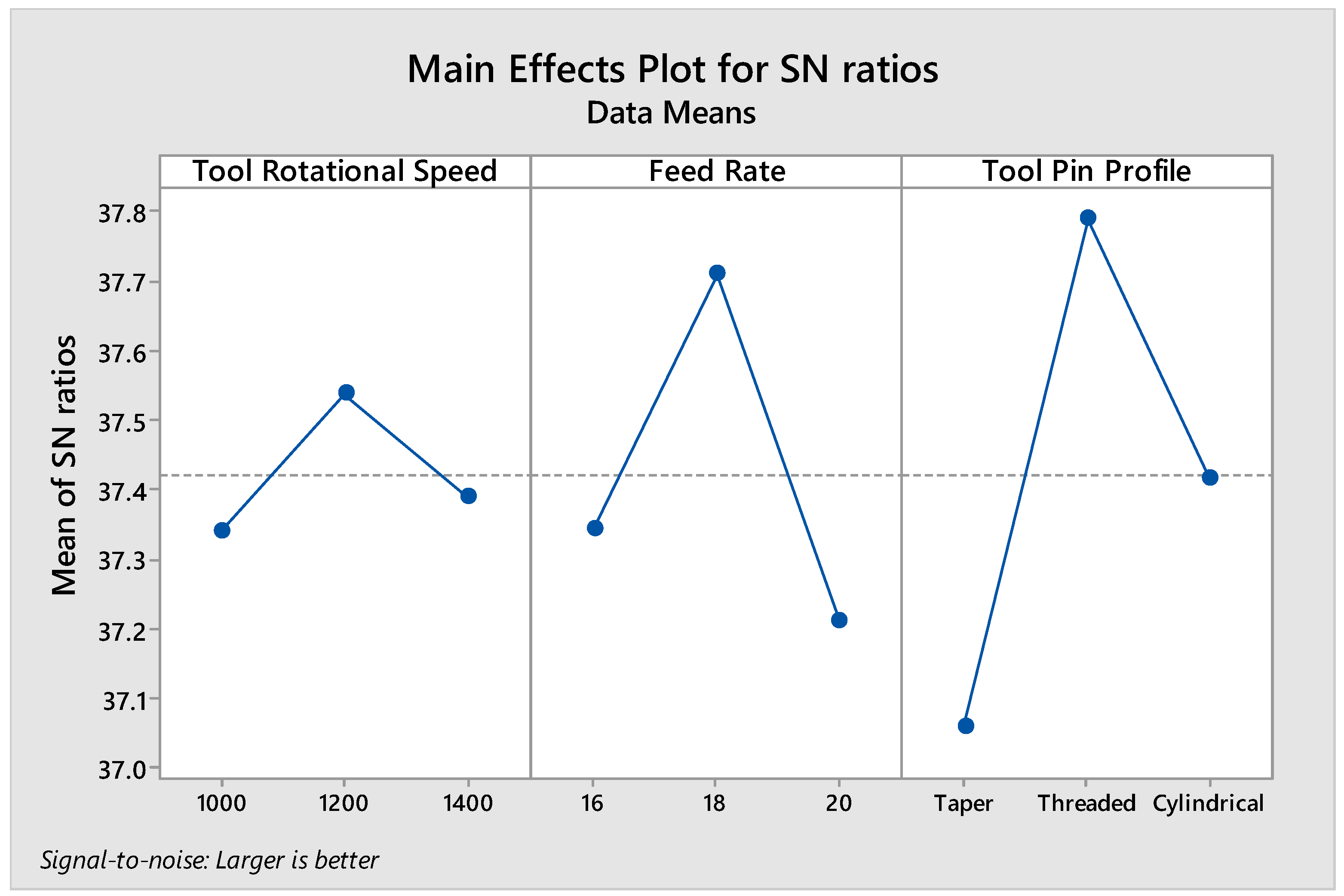
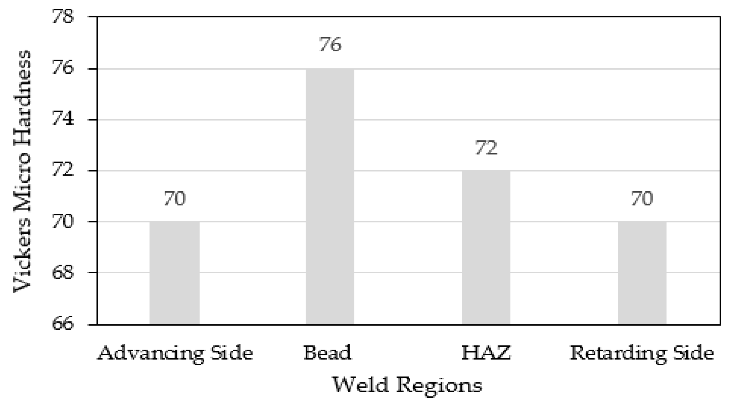
3.5. Hardness Properties at Optimum Level
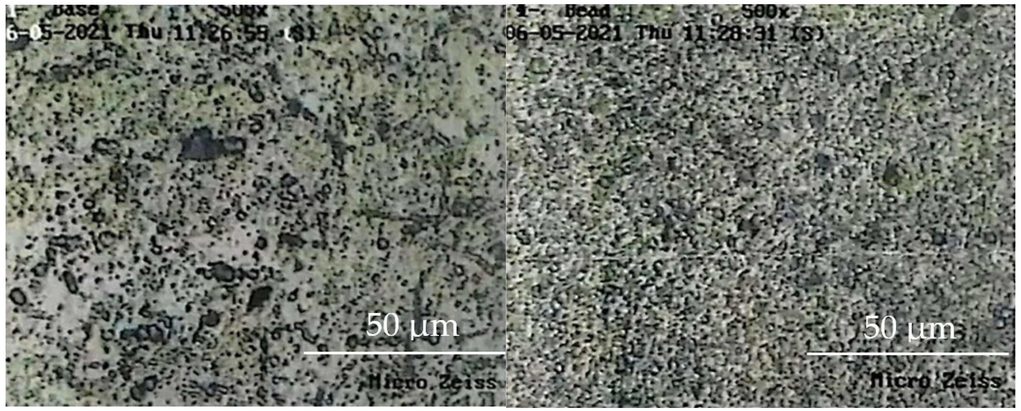
3.6. Microstructures at Optimum Level
4. Conclusions
- The highest value of tensile strength, i.e., 160.6907 Mpa, was calculated on the optimizer plot with optimum conditions of a 1400 tool rotation speed, a feed rate of 18 mm/min, and the tool pin with threads.
- The tensile strength of 157 Mpa was found experimentally for the specimen prepared using the optimum conditions, thus validating the computed results.
- The improved tensile strength was attributed to grain size refinement, which is directly related to the high rotational speed of the tool, sufficient feed rate, and geometry of the tool pin profile that provides better stirring action in the weld zone.
- The maximum value of hardness, i.e., 81.056 HV, was shown by friction stir welded joints fabricated using optimum conditions of a 1200 tool rotational speed, a feed rate of 18 mm/min, and a threaded tool pin profile.
- The higher value of Vickers microhardness was also observed in the friction stir zone due to the refining microstructure.
- Tool geometry was the major factor affecting tensile strength, contributing 67.77%, while feed rate has the least effect on tensile strength, contributing 9.78%.
- Tool geometry was the major factor affecting the hardness, contributing 62.42%, while tool rotation speed has the least effect on hardness, contributing 5%.
- The effectiveness and reliability of FSW joints for shipping industry applications can be observed by joint efficiency. That was investigated at optimum conditions, and it comes out to be 80.5%.
Author Contributions
Funding
Institutional Review Board Statement
Informed Consent Statement
Acknowledgments
Conflicts of Interest
References
- Wahid, M.A.; Siddiquee, A.N.; Khan, Z.A. Aluminum alloys in marine construction: Characteristics, application, and problems from a fabrication viewpoint. Mar. Syst. Ocean Technol. 2020, 15, 70–80. [Google Scholar] [CrossRef]
- Hosseinabadi, O.F.; Khedmati, M.R. A review on ultimate strength of aluminium structural elements and systems for marine applications. Ocean Eng. 2021, 232, 109153. [Google Scholar] [CrossRef]
- Martin, J.; Wei, S. Friction stir welding technology for marine applications. In Friction Stir Welding and Processing VIII; Springer: Berlin/Heidelberg, Germany, 2015; pp. 219–226. [Google Scholar]
- Starke, E.A., Jr.; Staley, J.T. Application of modern aluminum alloys to aircraft. Prog. Aerosp. Sci. 1996, 32, 131–172. [Google Scholar] [CrossRef]
- Abdi, B.; Koloor, S.; Abdullah, M.; Amran, A.; Yahya, M.Y. Effect of strain-rate on flexural behavior of composite sandwich panel. Appl. Mech. Mater. 2012, 229, 766–770. [Google Scholar] [CrossRef]
- Shah, I.A.; Khan, R.; Koloor, S.S.R.; Petrů, M.; Badshah, S.; Ahmad, S.; Amjad, M. Finite Element Analysis of the Ballistic Impact on Auxetic Sandwich Composite Human Body Armor. Materials 2022, 15, 2064. [Google Scholar] [CrossRef]
- Shokravi, H.; Mohammadyan-Yasouj, S.E.; Koloor, S.S.R.; Petrů, M.; Heidarrezaei, M. Effect of alumina additives on mechanical and fresh properties of self-compacting concrete: A review. Processes 2021, 9, 554. [Google Scholar] [CrossRef]
- Mazlan, S.; Yidris, N.; Koloor, S.S.R.; Petrů, M. Experimental and Numerical Analysis of Fatigue Life of Aluminum Al 2024-T351 at Elevated Temperature. Metals 2020, 10, 1581. [Google Scholar] [CrossRef]
- Kishta, E.E.; Darras, B. Experimental investigation of underwater friction-stir welding of 5083 marine-grade aluminum alloy. Proc. Inst. Mech. Eng. Part B J. Eng. Manuf. 2016, 230, 458–465. [Google Scholar] [CrossRef]
- Nia, A.B.; Nejad, A.F.; Xin, L.; Ayob, A.; Yahya, M.Y.; Koloor, S.S.R.; Petrů, M.; Hassan, S.A. Dynamic response of aluminium sheet 2024-T3 subjected to close-range shock wave: Experimental and numerical studies. J. Mater. Res. Technol. 2021, 10, 349–362. [Google Scholar]
- Chow, Z.P.; Ahmad, Z.; Wong, K.J.; Koloor, S.S.R.; Petrů, M. Thermal Delamination Modelling and Evaluation of Aluminium–Glass Fibre-Reinforced Polymer Hybrid. Polymers 2021, 13, 492. [Google Scholar] [CrossRef]
- Kashyzadeh, K.R.; Rahimian Koloor, S.S.; Omidi Bidgoli, M.; Petrů, M.; Amiri Asfarjani, A. An optimum fatigue design of polymer composite compressed natural gas tank using hybrid finite element-response surface methods. Polymers 2021, 13, 483. [Google Scholar] [CrossRef]
- Praveen, P.; Yarlagadda, P. Meeting challenges in welding of aluminum alloys through pulse gas metal arc welding. J. Mater. Process. Technol. 2005, 164, 1106–1112. [Google Scholar]
- Cheng, Y.; Hu, Y.; Xu, J.; Yu, L.; Huang, T.; Zhang, H. Studies on Microstructure and Properties of TiB2-Al3Ti Ceramic Particles Reinforced Spray-Formed 7055 Aluminum Alloy Fusion Welded Joints. J. Mater. Res. Technol. 2022, 19, 1298–1311. [Google Scholar]
- Morozova, I.; Królicka, A.; Obrosov, A.; Yang, Y.; Doynov, N.; Weiß, S.; Michailov, V. Precipitation phenomena in impulse friction stir welded 2024 aluminium alloy. Mater. Sci. Eng. A 2022, 852, 143617. [Google Scholar] [CrossRef]
- Arunprasad, R.; Surendhiran, G.; Ragul, M.; Soundarrajan, T.; Moutheepan, S.; Boopathi, S. Review on friction stir welding process. Int. J. Appl. Eng. Res. ISSN 2018, 13, 5750–5758. [Google Scholar]
- Chauhan, A.; Kumar, S. Impact strength of joints of aluminium matrix composite formed using friction stir welding technique. Mater. Today Proc. 2021, 38, 234–236. [Google Scholar] [CrossRef]
- Baratzadeh, F.; Boldsaikhan, E.; Nair, R.; Burford, D.; Lankarani, H. Investigation of mechanical properties of AA6082-T6/AA6063-T6 friction stir lap welds. J. Adv. Join. Process. 2020, 1, 100011. [Google Scholar] [CrossRef]
- Cabibbo, M. Friction Stir Welding Prospective on Light-Alloys Joints. Metals 2022, 12, 560. [Google Scholar] [CrossRef]
- Nguyen, T.V.; Huynh, N.-T.; Vu, N.-C.; Kieu, V.N.; Huang, S.-C. Optimizing compliant gripper mechanism design by employing an effective bi-algorithm: Fuzzy logic and ANFIS. Microsyst. Technol. 2021, 27, 3389–3412. [Google Scholar] [CrossRef]
- Wang, C.-N.; Yang, F.-C.; Nguyen, V.T.T.; Nguyen, Q.M.; Huynh, N.T.; Huynh, T.T. Optimal Design for Compliant Mechanism Flexure Hinges: Bridge-Type. Micromachines 2021, 12, 1304. [Google Scholar]
- Boldsaikhan, E.; McCoy, M. Analysis of tool feedback forces and material flow during friction stir welding. In Friction Stir Welding and Processing VII; Springer: Berlin/Heidelberg, Germany, 2013; pp. 311–320. [Google Scholar]
- Venkateswarlu, D.; Mandal, N.; Mahapatra, M.; Harsh, S. Tool design effects for FSW of AA7039. Weld. J. 2013, 92, 41–47. [Google Scholar]
- Gomathisankar, M.; Gangatharan, M.; Pitchipoo, P. A novel optimization of friction stir welding process parameters on aluminum alloy 6061-T6. Mater. Today Proc. 2018, 5, 14397–14404. [Google Scholar] [CrossRef]
- Dawood, H.; Mohammed, K.S.; Rahmat, A.; Uday, M. Effect of small tool pin profiles on microstructures and mechanical properties of 6061 aluminum alloy by friction stir welding. Trans. Nonferrous Met. Soc. China 2015, 25, 2856–2865. [Google Scholar] [CrossRef]
- Shojaeefard, M.H.; Khalkhali, A.; Akbari, M.; Tahani, M. Application of Taguchi optimization technique in determining aluminum to brass friction stir welding parameters. Mater. Des. 2013, 52, 587–592. [Google Scholar] [CrossRef]
- Boldsaikhan, E.; Corwin, E.M.; Logar, A.M.; Arbegast, W.J. The use of neural network and discrete Fourier transform for real-time evaluation of friction stir welding. Appl. Soft Comput. 2011, 11, 4839–4846. [Google Scholar] [CrossRef]
- Msomi, V.; Mbana, N.; Mabuwa, S. Microstructural analysis of the friction stir welded 1050-H14 and 5083-H111 aluminium alloys. Mater. Today Proc. 2020, 26, 189–192. [Google Scholar] [CrossRef]
- Nakowong, K.; Sillapasa, K. Optimized Parameter for Butt Joint in Friction Stir Welding of Semi-Solid Aluminum Alloy 5083 Using Taguchi Technique. J. Manuf. Mater. Process. 2021, 5, 88. [Google Scholar] [CrossRef]
- Cheng, Y.-W.; Read, D.T.; McColskey, J.D.; Wright, J.E. A tensile-testing technique for micrometer-sized free-standing thin films. Thin Solid Film. 2005, 484, 426–432. [Google Scholar]
- Aamir, M.; Tolouei-Rad, M.; Giasin, K.; Vafadar, A. Feasibility of tool configuration and the effect of tool material, and tool geometry in multi-hole simultaneous drilling of Al2024. Int. J. Adv. Manuf. Technol. 2020, 111, 861–879. [Google Scholar] [CrossRef]
- Rambabu, G.; Naik, D.B.; Rao, C.V.; Rao, K.S.; Reddy, G.M. Optimization of friction stir welding parameters for improved corrosion resistance of AA2219 aluminum alloy joints. Def. Technol. 2015, 11, 330–337. [Google Scholar] [CrossRef] [Green Version]
- Krishnaiah, K.; Shahabudeen, P. Applied Design of Experiments and Taguchi Methods; PHI Learning Pvt. Ltd.: Dehli, India, 2012. [Google Scholar]
- Ali, M.H.; Wadallah, H.M.; Ibrahim, M.A.; Alomar, O.A. Improving the Microstructure and Mechanical Properties of Aluminium Alloys Joints by Adding SiC Particles During Friction Stir Welding Process. Metallogr. Microstruct. Anal. 2021, 10, 302–313. [Google Scholar] [CrossRef]
- Cavaliere, P.; Panella, F. Effect of tool position on the fatigue properties of dissimilar 2024-7075 sheets joined by friction stir welding. J. Mater. Process. Technol. 2008, 206, 249–255. [Google Scholar] [CrossRef]
- Koilraj, M.; Sundareswaran, V.; Vijayan, S.; Rao, S.K. Friction stir welding of dissimilar aluminum alloys AA2219 to AA5083–Optimization of process parameters using Taguchi technique. Mater. Des. 2012, 42, 1–7. [Google Scholar] [CrossRef]
- Sato, Y.S.; Urata, M.; Kokawa, H.; Ikeda, K. Hall–Petch relationship in friction stir welds of equal channel angular-pressed aluminium alloys. Mater. Sci. Eng. A 2003, 354, 298–305. [Google Scholar] [CrossRef]
- Yong-Jai, K.; Seong-Beom, S.; Dong-Hwan, P. Friction stir welding of 5052 aluminum alloy plates. Trans. Nonferrous Met. Soc. China 2009, 19, s23–s27. [Google Scholar]


| Al | Si | Mg | Fe | Cr | Mn | Cu | V | Ti | Zn | P |
|---|---|---|---|---|---|---|---|---|---|---|
| 97.19% | 0.07% | 2.23% | 0.17% | 0.2% | 0.08% | 0.004% | 0.02% | 0.02% | 0.01% | 0.002% |
| Factors | Level 1 | Level 2 | Level 3 |
|---|---|---|---|
| Tool Rotation Speed (rpm) | 1000 | 1200 | 1400 |
| Feed Rate (mm/min) | 16 | 18 | 20 |
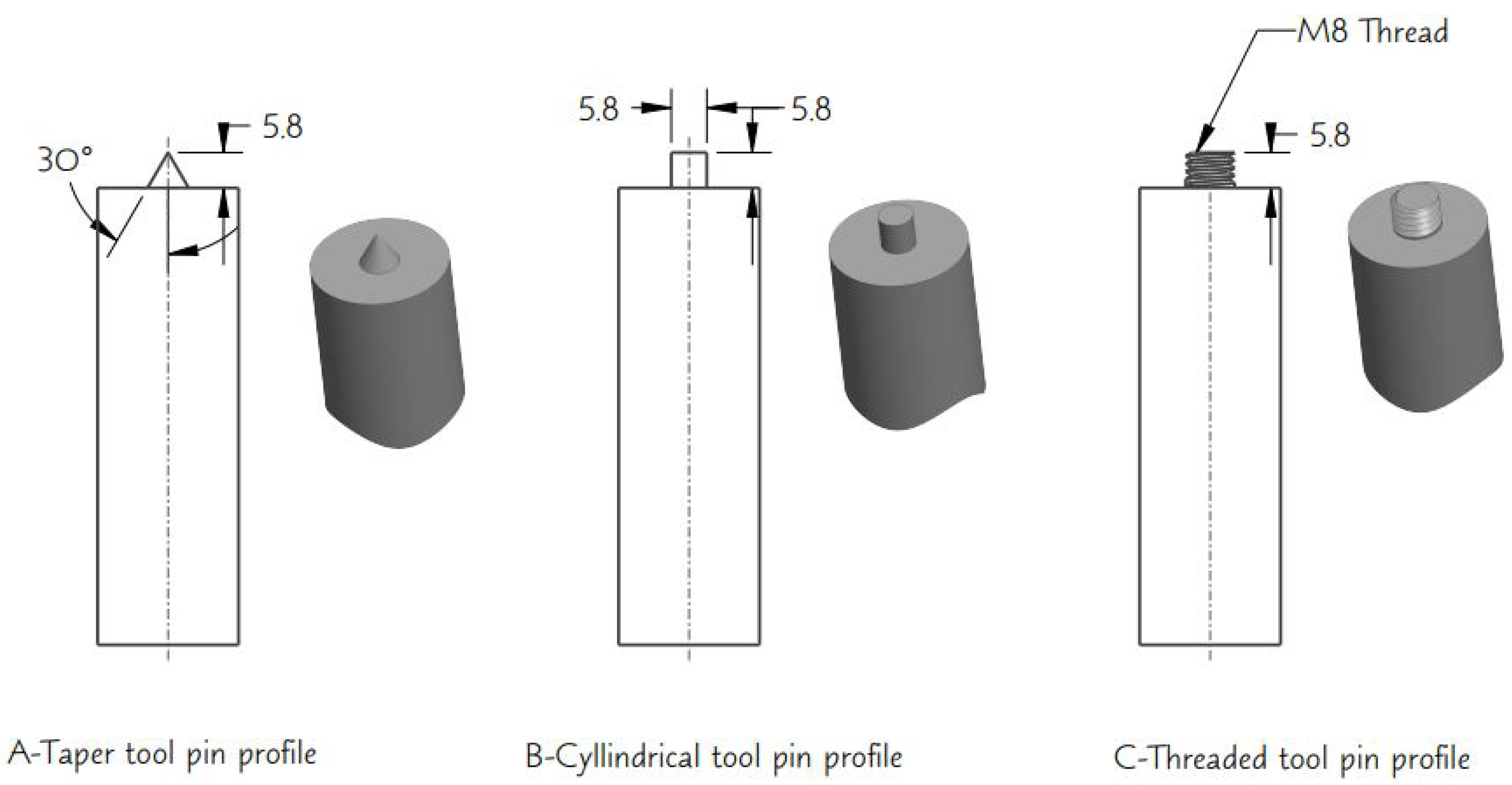
| Tool Pin Profile | Taper | Threaded | Cylindrical |
| Sr. No | Tool Rotation Speed (rpm) | Feed Rate (mm/min) | Tool Pin Profile |
|---|---|---|---|
| 1 | 1000 | 16 | Taper |
| 2 | 1000 | 18 | Threaded |
| 3 | 1000 | 20 | Cylindrical |
| 4 | 1200 | 16 | Threaded |
| 5 | 1200 | 18 | Cylindrical |
| 6 | 1200 | 20 | Taper |
| 7 | 1400 | 16 | Cylindrical |
| 8 | 1400 | 18 | Taper |
| 9 | 1400 | 20 | Threaded |
| Trial No | Orthogonal Array with Control Factors | Experimental Layout with Control Factors and Levels | Experimental Results | S/N Ratios | ||||||
|---|---|---|---|---|---|---|---|---|---|---|
| Tool Rotational Speed | Feed Rate | Tool Pin Profile | Tool Rotational Speed | Feed Rate | Pin Profile of Tool | Tensile Strength (Mpa) | Hardness (Weld Zone) | Tensile Strength (Mpa) | Hardness (Weld Zone) | |
| 1 | 1 | 1 | 1 | 1000 | 16 | Taper | 110.91 | 69.5 | 40.8996 | 36.8397 |
| 2 | 1 | 2 | 2 | 1000 | 18 | Threaded | 150.60 | 79.6 | 43.5565 | 38.0183 |
| 3 | 1 | 3 | 3 | 1000 | 20 | Cylindrical | 120.20 | 72.1 | 41.5981 | 37.1587 |
| 4 | 2 | 1 | 2 | 1200 | 16 | Threaded | 155.80 | 78.2 | 43.8513 | 37.8641 |
| 5 | 2 | 2 | 3 | 1200 | 18 | Cylindrical | 127.60 | 77.3 | 42.1170 | 37.7636 |
| 6 | 2 | 3 | 1 | 1200 | 20 | Taper | 118.90 | 70.7 | 41.5036 | 36.9884 |
| 7 | 3 | 1 | 3 | 1400 | 16 | Cylindrical | 139.00 | 73.5 | 42.8603 | 37.3257 |
| 8 | 3 | 2 | 1 | 1400 | 18 | Taper | 136.70 | 73.7 | 42.7154 | 37.3493 |
| 9 | 3 | 3 | 2 | 1400 | 20 | Threaded | 143.66 | 74.9 | 43.1467 | 37.4896 |
| S/N Ratio Response Values for Tensile Strength | |||
|---|---|---|---|
| Level | Tool Rotational Speed (rpm) | Feed Rate (mm/min) | Tool Pin Profile |
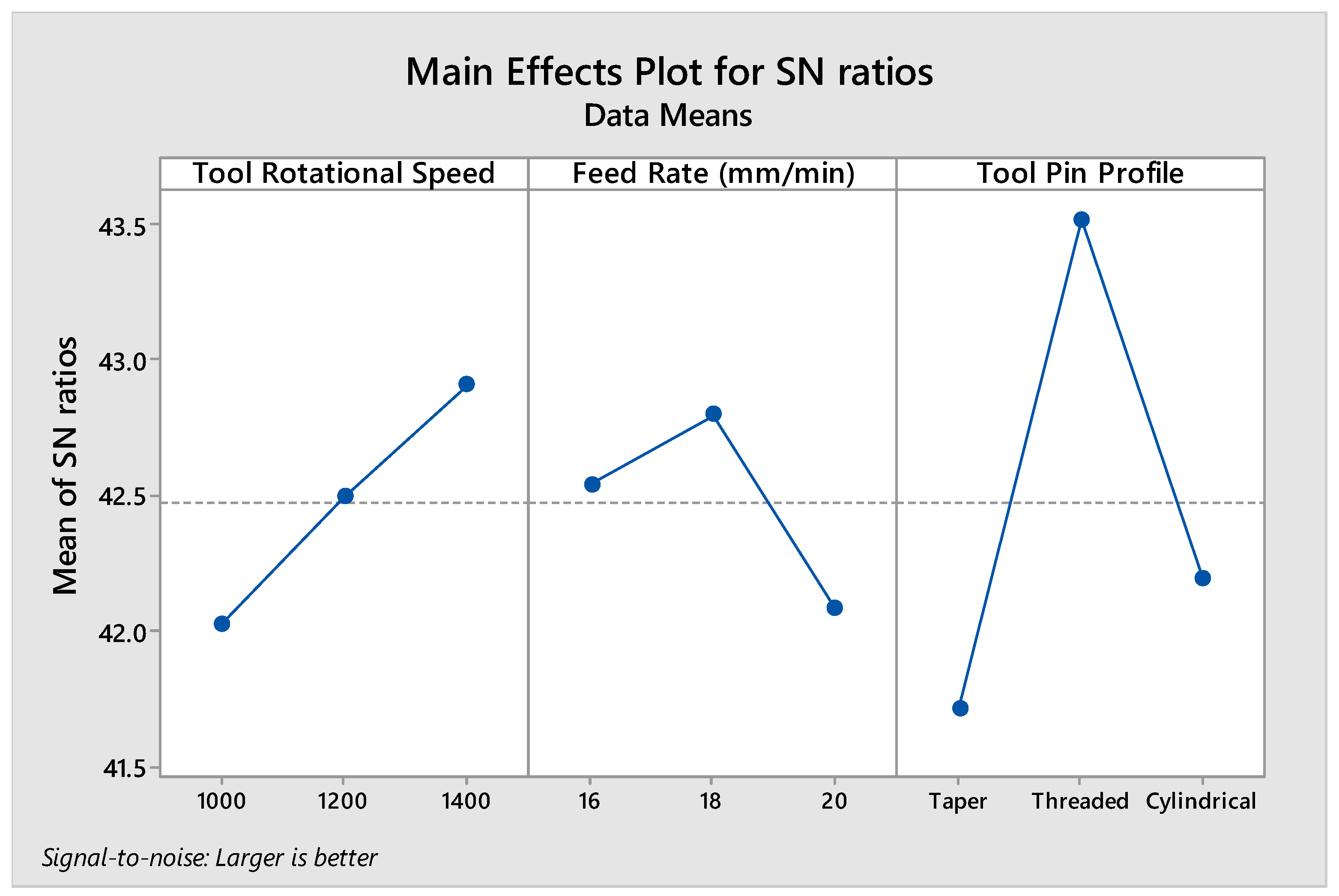
| 1 | 42.02 | 42.54 | 41.71 |
| 2 | 42.49 | 42.80a | 43.52a |
| 3 | 42.91a | 42.08 | 42.19 |
| Delta | 0.89 | 0.71 | 1.81 |
| Rank | 2 | 3 | 1 |
| S/N Ratio Response Values for Hardness | |||
| Level | Tool Rotational Speed (rpm) | Feed Rate (mm/min) | Tool Pin Profile |
| 1 | 37.34 | 37.34 | 37.06 |
| 2 | 37.54a | 37.71a | 37.79a |
| 3 | 37.39 | 37.21 | 37.42 |
| Delta | 0.20 | 0.5 | 0.73 |
| Rank | 3 | 2 | 1 |
| Source | D.F | Seq. SS | Contribution | Adj. SS | Adj. MS | F-Value | p-Value |
|---|---|---|---|---|---|---|---|
| Tensile Strength | |||||||
| Tool Rotation Speed | 2 | 236.9 | 12.68% | 236.9 | 118.46 | 1.30 | 0.435 |
| Feed Rate | 2 | 182.7 | 9.78% | 182.7 | 91.34 | 1.00 | 0.500 |
| Pin Profile of Tool | 2 | 1266.0 | 67.77% | 1266.0 | 632.98 | 6.94 | 0.126 |
| Error | 2 | 182.5 | 9.77% | 182.5 | 91.26 | - | - |
| Total | 8 | 1868.1 | 100.00% | - | - | - | - |
| Hardness (Weld Zone) | |||||||
| Tool Rotation Speed | 2 | 4.74 | 5.01% | 4.74 | 2.368 | 4.38 | 0.186 |
| Feed Rate | 2 | 29.67 | 31.42% | 29.67 | 14.834 | 27.41 | 0.035 |
| Pin Profile of Tool | 2 | 58.94 | 62.42% | 58.94 | 29.471 | 54.46 | 0.018 |
| Error | 2 | 1.08 | 1.15% | 1.08 | 0.541 | - | - |
| Total | 8 | 94.43 | 100% | - | - | - | - |
| Parameters | ||||||
|---|---|---|---|---|---|---|
| Response | Goal | Lower | Target | Upper | Weight | Importance |
| Tensile strength (Mpa) | Maximum | 110.912 | 155.8 | - | 1 | 1 |
| Solution | ||||||
| Solution | Tool rotational speed | Feed rate | Tool pin profile | Tensile strength (Mpa) fit | Composite desirability | |
| 1 | 1400 | 18 | Threaded | 160.691 | 1 | |
| Multiple Response Prediction | ||||||
| Variable | Setting | |||||
| Tool rotation speed | 1400 | |||||
| Feed rate | 18 | |||||
| Pin profile of the tool | Threaded | |||||
| Response | Fit | SE Fit | 95% CI | 95% PI | ||
| Tensile strength (Mpa) | 160.69 | 8.43 | (124.44, 196.94) | (105.88, 215.50) | ||
| Parameters | ||||||
|---|---|---|---|---|---|---|
| Response | Goal | Lower | Target | Upper | Weight | Importance |
| Hardness (Hv) | Maximum | 69.5 | 79.6 | 1 | 1 | |
| Solution | ||||||
| Solution | Tool rotational speed | Feed rate | Tool Pin profile | Hardness (Hv) Fit | Composite Desirability | |
| 1 | 1200 | 18 | Threaded | 81.0556 | 1 | |
| Multiple Response Prediction | ||||||
| Variable | Setting | |||||
| Tool Rotation Speed | 1200 | |||||
| Feed rate | 18 | |||||
| Pin Profile of tool | Threaded | |||||
| Response | Fit | SE Fit | 95% CI | 95% PI | ||
| Hardness (Hv) | 81.056 | 0.649 | (78.264, 83.847) | (76.835, 85.276) | ||
Publisher’s Note: MDPI stays neutral with regard to jurisdictional claims in published maps and institutional affiliations. |
© 2022 by the authors. Licensee MDPI, Basel, Switzerland. This article is an open access article distributed under the terms and conditions of the Creative Commons Attribution (CC BY) license (https://creativecommons.org/licenses/by/4.0/).
Share and Cite
Ahmed, S.; Rahman, R.A.u.; Awan, A.; Ahmad, S.; Akram, W.; Amjad, M.; Yahya, M.Y.; Rahimian Koloor, S.S. Optimization of Process Parameters in Friction Stir Welding of Aluminum 5451 in Marine Applications. J. Mar. Sci. Eng. 2022, 10, 1539. https://doi.org/10.3390/jmse10101539
Ahmed S, Rahman RAu, Awan A, Ahmad S, Akram W, Amjad M, Yahya MY, Rahimian Koloor SS. Optimization of Process Parameters in Friction Stir Welding of Aluminum 5451 in Marine Applications. Journal of Marine Science and Engineering. 2022; 10(10):1539. https://doi.org/10.3390/jmse10101539
Chicago/Turabian StyleAhmed, Shoaib, Rana Atta ur Rahman, Awais Awan, Sajjad Ahmad, Waseem Akram, Muhammad Amjad, Mohd Yazid Yahya, and Seyed Saeid Rahimian Koloor. 2022. "Optimization of Process Parameters in Friction Stir Welding of Aluminum 5451 in Marine Applications" Journal of Marine Science and Engineering 10, no. 10: 1539. https://doi.org/10.3390/jmse10101539