Article

Design and Testing of a Directional Clamping and Reverse Breaking Device for Corn Straw

1
College of Mechanical and Electrical Engineering, Henan Agricultural University, Zhengzhou 450002, China
2
Research Center of Low-Carbon Agricultural Intelligent Equipment Engineering Technology in Henan Provence, Zhengzhou 450002, China
*
Author to whom correspondence should be addressed.
Agriculture 2023, 13(8), 1506; https://doi.org/10.3390/agriculture13081506
Submission received: 21 June 2023 / Revised: 20 July 2023 / Accepted: 24 July 2023 / Published: 27 July 2023
(This article belongs to the Special Issue Design, Optimization and Analysis of Agricultural Machinery)

Abstract

:
Realizing high-quality and increased production of fresh corn and promoting diversified development of the corn industry structure not only can effectively promote the development of agricultural economy, but also can enrich people’s dietary culture. However, existing fresh corn machinery has a high rate of ear damage during the harvesting process, and the overall harvesting efficiency is not ideal. To reduce damage during the harvesting of fresh corn, a device for breaking ears of fresh corn was designed based on the directional clamping of corn straw reverse breaking method. Based on the physico-mechanical characteristics parameters of fresh corn ears, the main structural parameters of the directional clamping and conveying mechanism and the ear-breaking mechanism were determined. The overall inclination angle of the device was 15°, and the effective conveying length of the directional clamping mechanism was 550 mm; the ear-snapping mechanism was a snapping roll composed of a pair of six radial distribution function fingers, with an effective operating radius of 320 mm. By simulating and analyzing the reverse breaking movement of directional clamping corn straw, the key motion parameter ranges of the directional clamping conveying mechanism and breaking mechanism were obtained. The results of the bench test showed that under the optimal conditions of a directional clamping feeding speed of 1.67 m/s, a breaking wheel speed of 80 rpm, and a travel speed of 1.06 m/s, the lowest ear damage rate was 0.57%, and the lowest impurity rate was 1.87%. In addition, it was observed that flexible harvesting can improve harvest efficiency and quality. The study also found that actively applying force to the device can effectively avoid the problem of machine blockage and reduce the damage rate of ears (the following text uses ears instead of fresh corn ears).

1. Introduction

Fresh corn, also known as fruit corn, is usually picked during the milk ripening period and is a nutritious and delicious vegetable suitable for different populations. With the support of relevant policies, the fresh corn industry has developed rapidly [1,2]. Fresh corn has characteristics such as high moisture content, thin skin, poor grain compression resistance, and susceptibility to damage. During the process of picking and transporting ears, it is necessary to maintain the integrity of the ears to the greatest extent possible to ensure the quality of the crops after harvest [3]. The traditional process of harvesting fresh corn is manual harvesting, which not only has low efficiency but also leads to a shortage of labor. The mechanized harvesting of fresh corn is an effective means to solve the current problem of rural labor shortage, which can increase farmers’ enthusiasm for planting, reduce labor intensity, and promote yield increase and harvest [4]. However, due to significant climate differences in different regions, corn planting modes and harvesting methods are also divided into various types. In practice, specialized fresh corn harvesters are often used for harvesting operations [5,6], and the market penetration rate of specialized harvesting machinery is relatively low [7,8,9].
At present, fresh corn harvesters that simulate manual picking methods have become a potential solution to the problem of a high rate of ear damage during harvesting [10,11]. So far, relevant scholars have conducted research on harvesting machinery for fresh corn and reduced the damage rate of ears. According to the literature review, the structural improvement of the ear-picking device may have a significant impact on the optimization of the above issues [12,13]. Regarding the research on fresh corn ear-picking devices, existing device types inevitably encounter phenomena such as corn ear biting, broken stems, and machine blockage, which affects the application of corn harvesters [14].
The ear-picking device is the most important working component of a corn harvester, which directly affects the quality of harvested ears [13]. The ear-picking device is divided into the horizontal roller type, the stem-pulling roller and ear-picking plate combination type, the biomimetic ear-picking type, etc. according to its structure [15]. The horizontal roller type ear-picking device can achieve effective harvesting of fresh corn through the difference in torque force and friction force. For example, Zhansheng Zhang et al. [16] (2021) used a horizontal roller type ear-picking mechanism longitudinally configured with high- and low-torsion rollers to simulate the operation process of manually breaking fresh corn. The combined ear-picking device of stem-pulling roller and ear-picking plate reduces the power loss during the ear-picking process by adding an ear-picking plate above the stem-pulling roller [17] (Tianyu Li, 2019). Guanqiang Zhu et al. [11] (2023) designed a corresponding ear-picking device using a biomimetic ear-picking method. This scheme adopted a new ear-harvesting posture adjustment method, and the average power consumption of the entire device was reduced to over 3.0 kW. Xirui Zhang et al. [18] (2019) used an oblique roller to break the ears of fresh corn, separating them from the stems and achieving the harvest requirements for crispy and tender corn.
Because most of the existing corn-harvesting machines on the market are horizontal roller harvesting mechanisms and have a large inventory, it is possible to improve and optimize the existing harvesting devices, which can save energy and protect the environment [19]. This study aims to design an ear-breaking device for harvesting fresh corn and verify its feasibility, especially to determine how the flexible ear-picking mechanism affects the breaking rate of ears.
This article proposes to design a new ear-breaking device for harvesting fresh corn based on the method of directional clamping of corn straw and reverse ear breaking. Based on clarifying the physico-mechanical properties of fresh corn, the key mechanisms of the ear-breaking device were optimized and designed; aimed at the goal of reducing the rate of ear damage and impurity content, a bench test was conducted using the orthogonal rotation center combination experimental design method to obtain and verify the optimal combination of key mechanism motion parameters, thereby providing theoretical and technical bases for the optimization design of fresh corn combine harvesters.

2. Design of Directional Clamping Corn Ear-Breaking Device

2.1. Design Requirement

The optimal harvest period for fresh corn is in the late stage of milk ripening and the early stage of wax ripening. At this time, the moisture content of the stems of fresh corn plants is higher, and compared to ordinary grain corn, the stems are thin and brittle. Completing the fresh corn ears picking operation can easily cause a higher ear impurity rate. Meanwhile, the moisture content of fresh corn kernels ranges from 65% to 75%, which can easily cause serious mechanical damage during the picking process, thereby affecting the quality and storage time of fresh corn and reducing its economic value. The design requirements for fresh corn ear picking equipment [20,21] are:
  • Reduce or avoid the possibility of mechanical collision between fresh corn ears and operating components, reduce the probability of mechanical damage to ears, and ensure that the crushing rate of fresh corn seeds is less than 1%.
  • Avoid cutting off the stems of fresh corn plants by the ear-picking device, ensure that the impurity content of fresh corn ears is less than 1.5%, and avoid blockage of the ear-picking device.

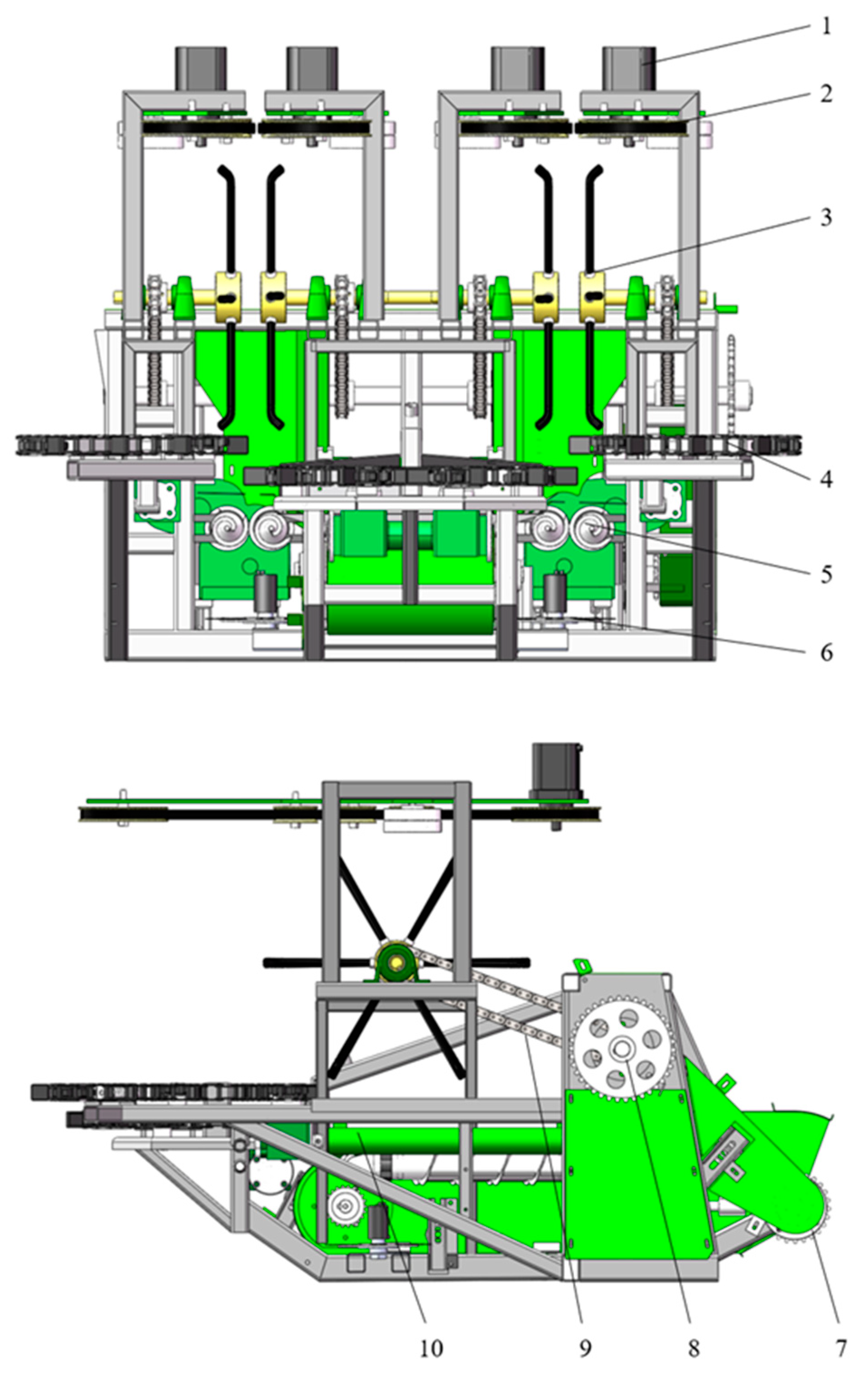
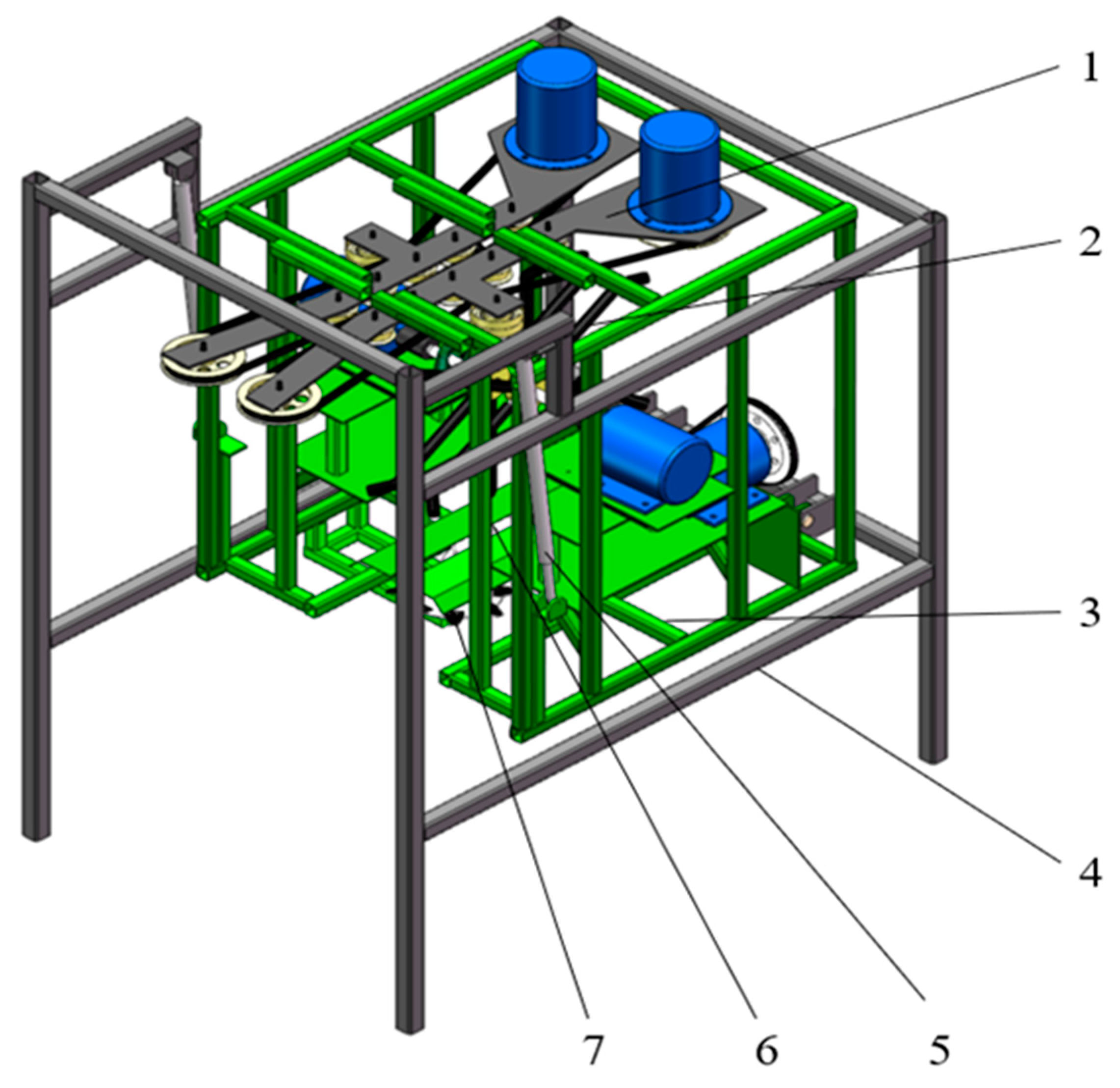
2.2. Structure and Working Principle

The directional clamping corn ear-breaking device is the header part of a corn combine harvester, mainly composed of a frame, a disc cutter device, a directional clamping mechanism, an ear-breaking mechanism, a stem-pulling mechanism, an ear collection mechanism, a transmission mechanism, etc. (Figure 1). When harvesting fresh corn, as the combine moves in opposite directions, the corn plant is continuously fed to the directional clamping conveying mechanism, which clamps the stem above the ears and delivers it to the breaking mechanism, and the ear breaking is completed under the action of ear-breaking rollers composed of a pair of six radial distribution function fingers. During the breaking process, the corn stalks were not cut, similar to the manual breaking process. The directional clamping mechanism played a role in supporting the breaking process. After the breaking operation was completed, the cutting knife cut the stalks, and the pulling roller squeezed the corn stalks to achieve continuous, stable production.

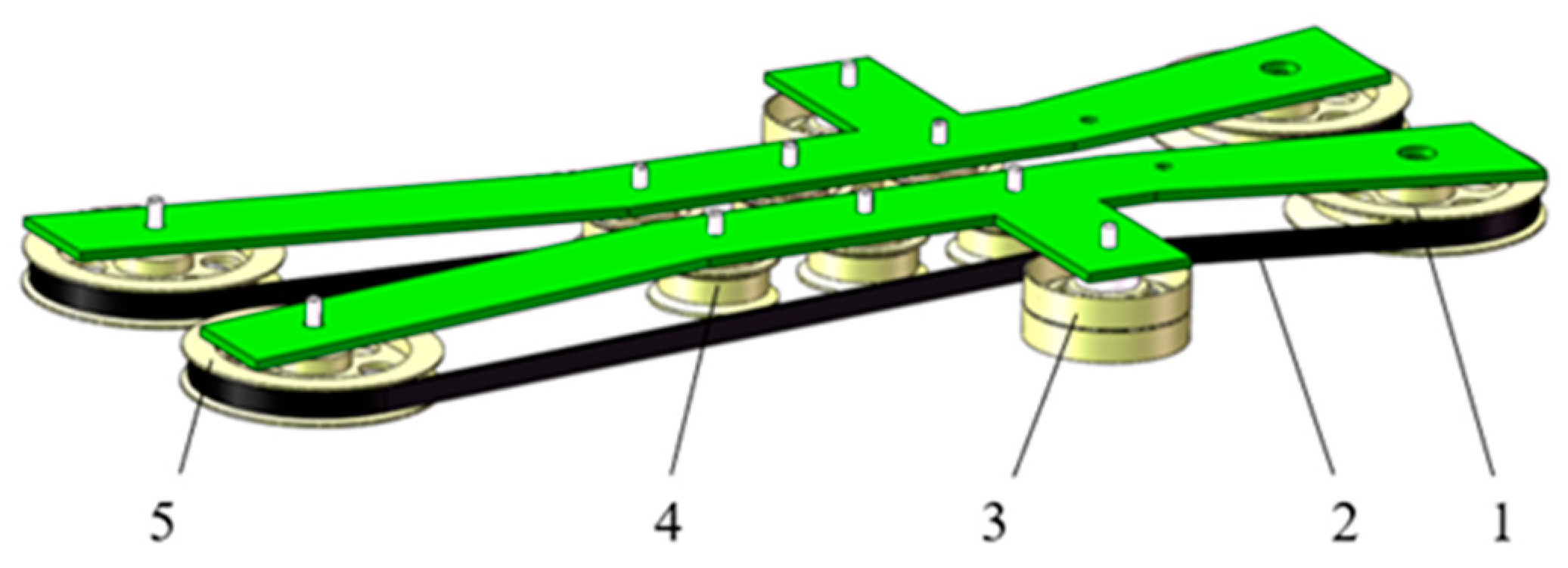
2.3. Directional Clamping Mechanism

As illustrated in Figure 2, the directional clamping mechanism imitates the manual breaking of corn stalks. Before butting the corn roots, the cutter is transported to the breaking mechanism under the action of the clamping belt and supports the corn stalks to ensure that the stalks are not broken. After the breaking of the ears is completed under the action of the breaking wheel fingers, the directional clamping and conveying process can be completed.
To ensure effective clamping of the stems during the clamping and conveying process, it is advisable to keep the clamping position within the same section of the stems as much as possible. Therefore, the inclination angle of the directional clamping and conveying mechanism should not be too large. According to the measurement of fresh corn plants, the diameter of the stems above the ears decreases as the height increases; therefore, the clamping position of the directional clamping and conveying system should be controlled, and the inclination angle should not be too large so ξ should satisfy:
sin ξ d m l f
In the formula, dm is the single stem length, mm; lf is the length of directional clamping and conveying mechanism, mm; ξ is the angle of device inclination, °.
Considering the clamping stability and structural layout during harvesting operations, an effective clamping conveying length of 550 mm was designed, and the calculated inclination range is 0° ≤ ξ ≤ 21°. Based on practical considerations, the inclination angle of the clamping and conveying mechanism is taken as ξ = 15°, and due to the integrity of the header, the overall tilt angle of the header is 15°.
To achieve effective clamping of the stems during the harvesting operation, the clamping and conveying speed exerts a significant influence on the breaking effect. To ensure the stability and efficiency of the breaking operation, the changes in the inclination angle and speed of the corn stems during the directional clamping and conveying process were estimated. As shown in Figure 3, during the process of ears breaking, if the forward speed of the machine is equal to the clamping and feeding speed of the stem, the rapid feeding of adjacent plants may affect the ear-breaking effect of a single plant. Therefore, to reduce the influence of the front plant on subsequent plants, the directional clamping and conveying speed should not be less than the forward speed of the machine.
In the analysis of the process of gripping corn plants, and during the ear-breaking operation, it is necessary to make the ears setting position Lj in the ear-breaking mechanism.
Above the minimum effective ear-breaking height H1, the tilt angle of the corn plant should be less than α1.
If the operating speed of the machine during field operations is vj and the spacing between plants is S1, then at time t1 when advancing by one pre-set unit spacing between plants:
t 1 = S 1 v j
In the formula, S1 is the single row spacing, mm; vj is the operation speed of machine, m/s.
During the directional clamping and conveying process, the upper end of the corn plant tilts to a certain extent under the action of the clamping and conveying mechanism to change the feeding posture of the fresh corn plant. When the critical condition is reached, the ears setting position tilts to the lowest effective ear-breaking height H1. At this point, adjacent corn plants also enter the feed inlet of the directional clamping conveyor mechanism, and the clamping conveyor time t2 is:
t 2 = L j × tan α v f × cos ξ
In the formula, vf is the speed of directional clamping and conveying mechanism, m/s.
If t1 = t2, then:
v f = L j × tan α 1 S 1 × cos ξ v j
According to the measurement of the characteristics of fresh corn plants, the range of ears height is 0.73–1.08 m, and the spacing between fresh corn plants is 0.25–0.35 m. The mechanical operation speed is taken as 0.85–1.35 m/s based on the existing harvester operation speed. The clamping conveyor belt speed vf is calculated from Equations (1) and (2) to be 1.83–2.92 m/s. According to the ratio between the machine forward speed and the clamping feeding speed, the maximum speed of the clamping conveyor mechanism is 1.83 m/s. In summary, the speed range of the directional clamping conveying mechanism is 1.35–1.83 m/s.

2.4. Design and Analysis of the Ear-Breaking Mechanism

The ear-breaking device is the core component of the corn harvester, and the harvesting efficiency and ear damage rate of fresh corn are determined mainly by the ear-breaking device. At present, there are two main types of corn ear-breaking devices: the roller type and the combination of ear-breaking plate and stem-pulling roller. When the roller-type ear-breaking mechanism is in harvesting operation, the direct contact between the ears and the ear-breaking roller can cause severe ear biting due to the high moisture content of fresh corn [22]. The combined ear-breaking device mainly uses the stem-pulling roller to pull the corn stem downward, and when the ears come into contact with the ear-breaking plate, the ears cannot pass through. When the separation occurs between the ears and stem, the instantaneous impact on the same part of the corn ear is greater, resulting in a higher rate of damage. At the same time, different collision conditions from different angles also cause different amounts of damage to the impact surface of fresh corn ears.

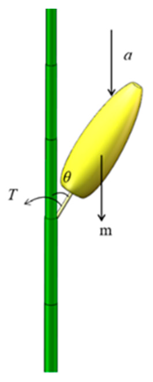
2.4.1. Stress Analysis of Fresh Corn Ears

The fresh corn-clamping and breaking device utilizes the breaking finger and the gravity of the ears itself to complete the breaking operation during the breaking operation, which can reduce the rate of damage to ears [23]. As shown in Figure 4, during the growth of fresh corn plants, the balance equation between the weight torque of corn ears and the torque T of stems under stable conditions is as follows:
T = G L 1 sin θ
Assuming that during the process of ears breaking, ears breaking refers to applying a downward acceleration a to the ears, the inertial force on the ears is given by:
m g L 1 sin θ + m a L 2 sin θ = m ( g L 1 + a L 2 ) sin θ
In the formula, m is the mass of an ear, kg; L1 is the distance from the center of gravity of the ear to the growth point, mm; L2 is the distance from the point of force application to the growth point, mm; θ is the angle between the ear and the stem, °.
According to Equation (6), the combined moment of gravity and force of the ears during the breaking process is greater than the torque of the stem when it is stable, so the breaking operation can be completed.
Therefore, compared to traditional ear-breaking methods, the reverse ear-breaking method requires less force to complete the ear-breaking operation under the self-weight of the ears.

2.4.2. Design of the Ear-Breaking Mechanism

To reduce the damage rate of fresh corn ears, an active ear-breaking wheel was designed based on the principle of manual ears breaking, which mainly consists of a rotating wheel hub, ear-breaking fingers, and flexible rubber sleeves, as shown in Figure 5.
When performing ear-breaking operations, ears breaking refers to the process of gradually increasing the force on the corn plant. Therefore, the relationship between the installation height of the rotation axis of the ear-breaking wheel and the average ear height should meet the following requirements:
H h ¯
By measuring the physical parameters of fresh corn, 50 plants of Wannuo 2018 and Starnuo 41 varieties were randomly selected during the harvest period. The physical characteristics [24] (including plant growth height, stem diameter, ear diameter, and ear height) of fresh corn plants were measured (Table 1).
Using a tensile tester to perform reverse breaking force testing on ears, the measured breaking force ranged from 36.8 N to 72.4 N. Mechanical properties were measured using a ZQ-890A mechanical (ZhiQu Precision Instrument Co., Ltd., Dongguan, China.) testing machine (with a force range of 100 kg/1 kN). Using the three-point bending measurement method, the average yield strength of the stem was found to be 9.26 MPa, the average compressive strength of the ears with bracts was 0.205 MPa, and the average compressive strength of the ears without bracts was 0.138 MPa.
The average ear height difference of a single variety is 296.5 mm, and the effective ear height difference is reduced under the action of the directional clamping conveyor mechanism, that is, dx ≤ 300 mm. Therefore, to ensure that all corn plants of the same variety can be within the effective ear-breaking range, the installation of the ear-breaking wheel rotation axis does not exceed the average ear-breaking height (a static analysis thereof is represented in Figure 6).
To ensure that fresh corn ears can enter the ear-breaking fingers, the distance between adjacent ear-breaking fingers should not be too small. If it is too small, it will prevent the ear-breaking fingers from acting on the ears, affecting the efficiency of the operation; therefore, the distance between adjacent fingers is such that:
d z = 2 l z × sin ρ 2
In the formula, dz is the distance between the fingers of two adjacent broken ears, mm; lz is the breaking finger length, mm; ρ is the angle between adjacent ear fingers, °.
Due to the differences in growth among different corn varieties, the angle between ears and stems is also different. Therefore, the effective length of ears in the vertical direction is:
d g = l g × cos β
In the formula, dg is the distance between the fingers of two adjacent broken ears, mm; lg is the breaking finger length, mm; β is the angle between ear and stem, °.
At the same time, the effective length dg of the ear in the vertical direction and the distance dz between adjacent ear fingers should meet the following requirements:
d g d z
According to the measurement of planting parameters for fresh corn plants in the field, the average plant spacing of fresh corn is 325 mm, and the machine operating speed is 1.2 m/s. During pre-testing, when the rate of rotation of the ear-breaking wheel is 90 rpm, the ear-breaking operation is good, so 90 rpm is used as a benchmark in subsequent calculations. The relationship between ear-breaking time interval and ear-breaking index is determined using Equation (11):
t = 60 n × z
In the equation, t is the interval time, s; n is the speed of spinning wheel, rpm; z is the number of broken ear fingers.
From Equation (11), the rate of rotation of the ear-breaking wheel is inversely proportional to the index of the ear-breaking finger. When the rotational speed of the ear-breaking wheel is a fixed value, the time interval between ear-breaking fingers decreases as the number of roots of the ear-breaking fingers increases. To ensure that there is no missed picking during the ear-breaking operation, Equation (12) must be satisfied:
t d v
In the equation, d is the plant spacing of fresh corn, mm; v is the forward speed of machine, m/s.
From this, it can be concluded that t ≤ 0.25 s. Considering the rotational balance and structural dimensions of the ear-breaking wheel, when z = 6, t = 0.11 s satisfies Equation (12).
In summary, the length of the ear-breaking fingers is 300 mm, and the number of ear-breaking fingers is 6. The inner part is an iron roller, and the outer part is a flexible rubber sleeve. The material used for the outer rubber sleeve is polyurethane, with a Shore hardness of 65A and a thickness of 7 mm.

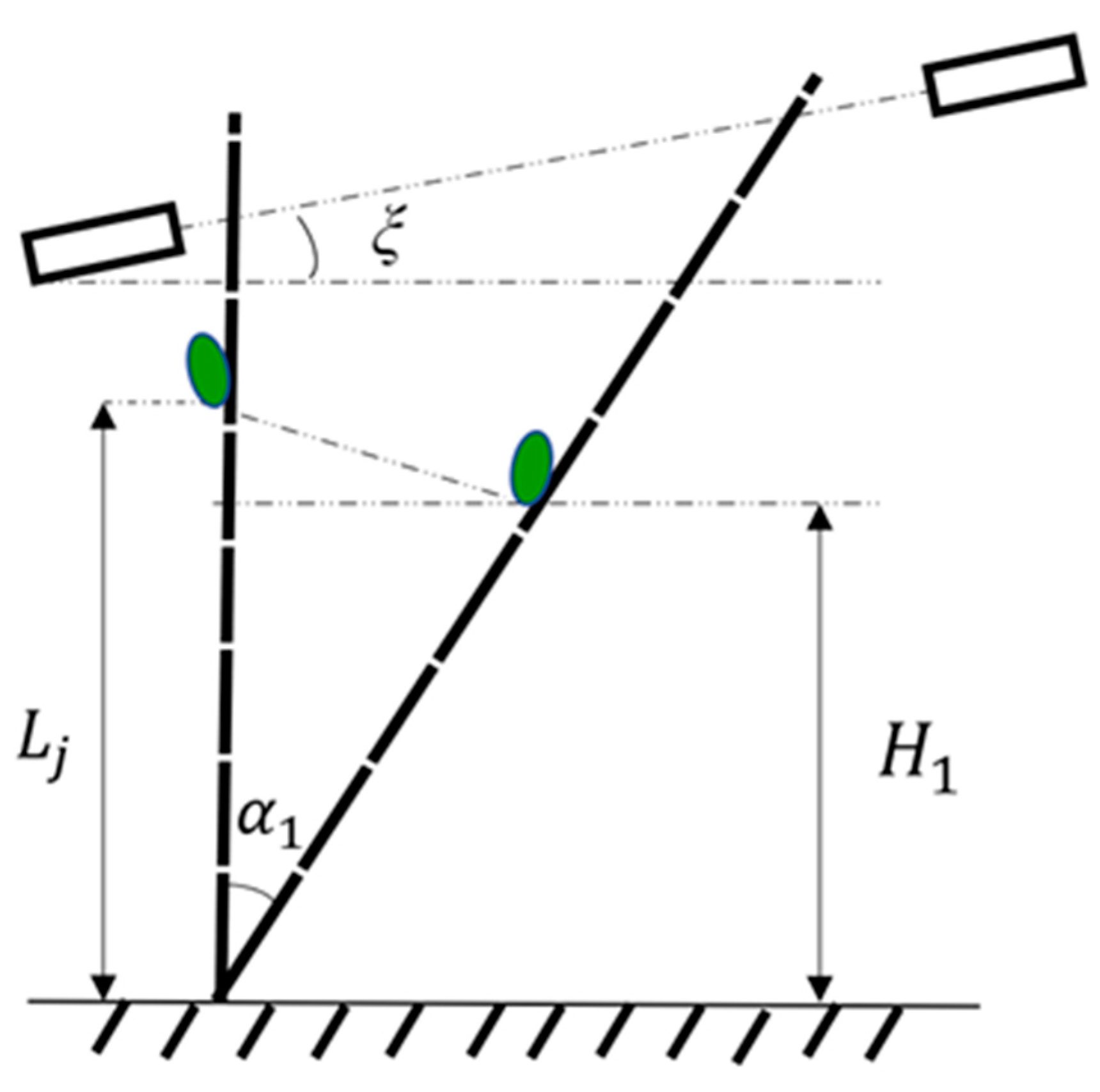
2.4.3. Analysis of the Effect of Breaking Ears on the Growth Angle of Fresh Corn Ears

When the ear-breaking wheel is used for the ear-breaking operation, the growth direction of fresh corn ears has a significant impact on the ear-breaking effect of the ear-breaking finger. Therefore, the gap between the ear-breaking fingers must meet the requirement of producing ear-breaking force for fresh corn ears growing in different directions. During the ear-breaking operation, the corn stem is directionally clamped and fed into the gap between the ear-breaking fingers. As the diameter of the ear is smaller than the gap, the ear-breaking finger can apply the ear-breaking force to separate the ear from the stem from top to bottom. Due to the randomness of the direction between the ears and the gap between the ear-breaking wheel during the operation of the machine, there are several states where the angle between the ears axis and the ear-breaking finger axis appears, as illustrated in Figure 7.
Based on the measurement data of the length of fresh corn ears and the angle between ear and stem, the horizontal projection lgz of the top of the ear to the axis of the stem can be calculated as:
l g j = l g × sin β
l g z = l g j × sin α s
From the above equation, in the unilateral case:
  • Fresh corn ears grow at a certain angle range in the opposite direction to the direction of motion of the harvesting machinery, and the angle between the ears and stems is: 0° ≤ αS < 31.2°. The ear-breaking force is applied to the top one-third of the ears, and as the ear-breaking finger rotates, the point of action of the resultant ear-breaking force slides down to the bottom of the ears;
  • Fresh corn ears grow at a certain angle range compared to harvesting machinery, and the angle between the ears and corn stems is 31.2° ≤ αS < 148.8°; the ear-breaking force is applied to the middle one-third of the ears by the ear-breaking finger. As the ear-breaking finger rotates, the point of action of the resultant ear-breaking force slides down to the bottom of the ears or even to the stem itself;
  • Fresh corn ears grow in the same direction as harvesting machinery, and the angle between the ears and stems is 148.8° ≤ αS ≤ 180°; the ear-breaking force is applied to the lower one-third of the ears by the ear-breaking finger. As the ear-breaking finger rotates, the point of action of the resultant ear-breaking force slides down to the top of the ears.
During this process, the stressed parts of fresh corn vary, so the impact force on the ears with bracts is a sliding impact. This breaking method can reduce the proportion of damaged ears.

2.4.4. Finite Element Analysis of Fruit Stem Bending Fracture

The solution idea of finite element method is to discretize a global solution domain into multiple small subdomains and connect them into a whole through adjacent nodes [25,26]. Xiaodong Guan et al. [23] investigated collisions of ears at different angles using ANSYS. This article aims to determine the impact of bending load on corn plants. The plant model was imported into ANSYS, and corresponding loads were applied to observe the effect. By adding forces, the effects of applied loads on the bending fracture trend of fruit stems were examined, and the theoretical analysis of ear picking was conducted.
In ANSYS Workbench, the designed three-dimensional model of fresh corn plants was imported and the mechanical properties parameters of fresh corn input [17] (as shown in Table 2):
The fresh corn plant was divided into grids and Boolean operations were used to connect the components. To ensure the independence of the three components, the Glue command in Boolean operations was used to connect the common boundaries of each component. To observe the stress analysis of the fracture site, the area where the stem is connected to the upper and lower sections of the fruit stem and the area where the fruit stem is connected to the ear was also meshed (Figure 8).
The fresh corn-clamping and breaking device designed in this article is fixed at both ends during the breaking operation, exerting a force on the ears. When bent to a certain extent, the ears are picked off; therefore, in finite element analysis, fresh corn plants are fixed and supported in both an up and down motion, and loads are added to the ears. According to the measurement of fresh corn ear-breaking force described in Section 2, the range of ear-breaking force is 36.8 to 72.4 N. Due to errors in experimental measurement, and based on the compressive strength data measured on the mechanical properties of corn ears, under the condition of meeting the compressive strength of corn ears with bracts, a force of 120 N is applied to the ears in a vertical downward direction. For the convenience of observation, the model style during deformation is retained in finite element analysis (by zooming in and out on the observed area). As shown in Figure 9a, there is a certain amount of deviation due to the thin upper stem of the spike. The stress cloud diagram of the connection between the fruit stem and the stem and ear after adding the load is shown in Figure 9b.
Through observation and research, it has been found that under uniform load applied to the surface of ears, force is transmitted to the fruit handle and straw, causing them to undergo bending deformation under load. The maximum stress concentration is found to be close to the point of connection between the fruit handle and straw; therefore, it can be determined that, when bending load is applied to the surface of the ears, the fruit handle will first bend and then break, and the breaking position is easy to occur near the connection position between the fruit handle and straw. Therefore, the reverse ear-breaking operation designed can be deemed reasonable.

3. Bench Test

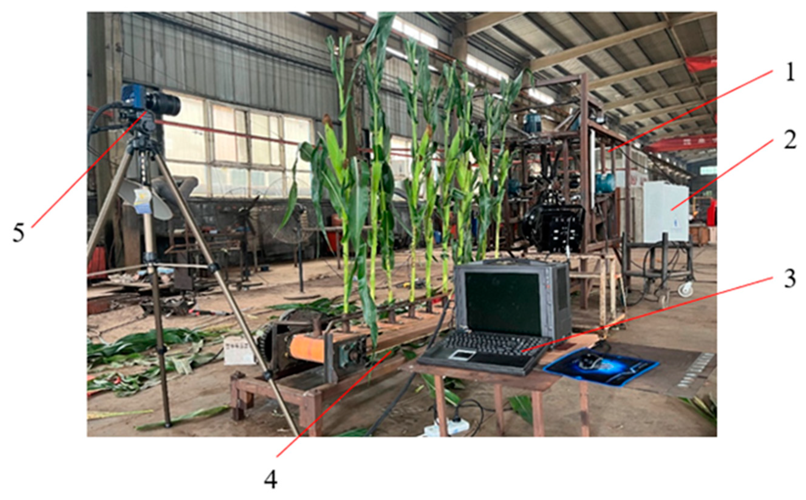
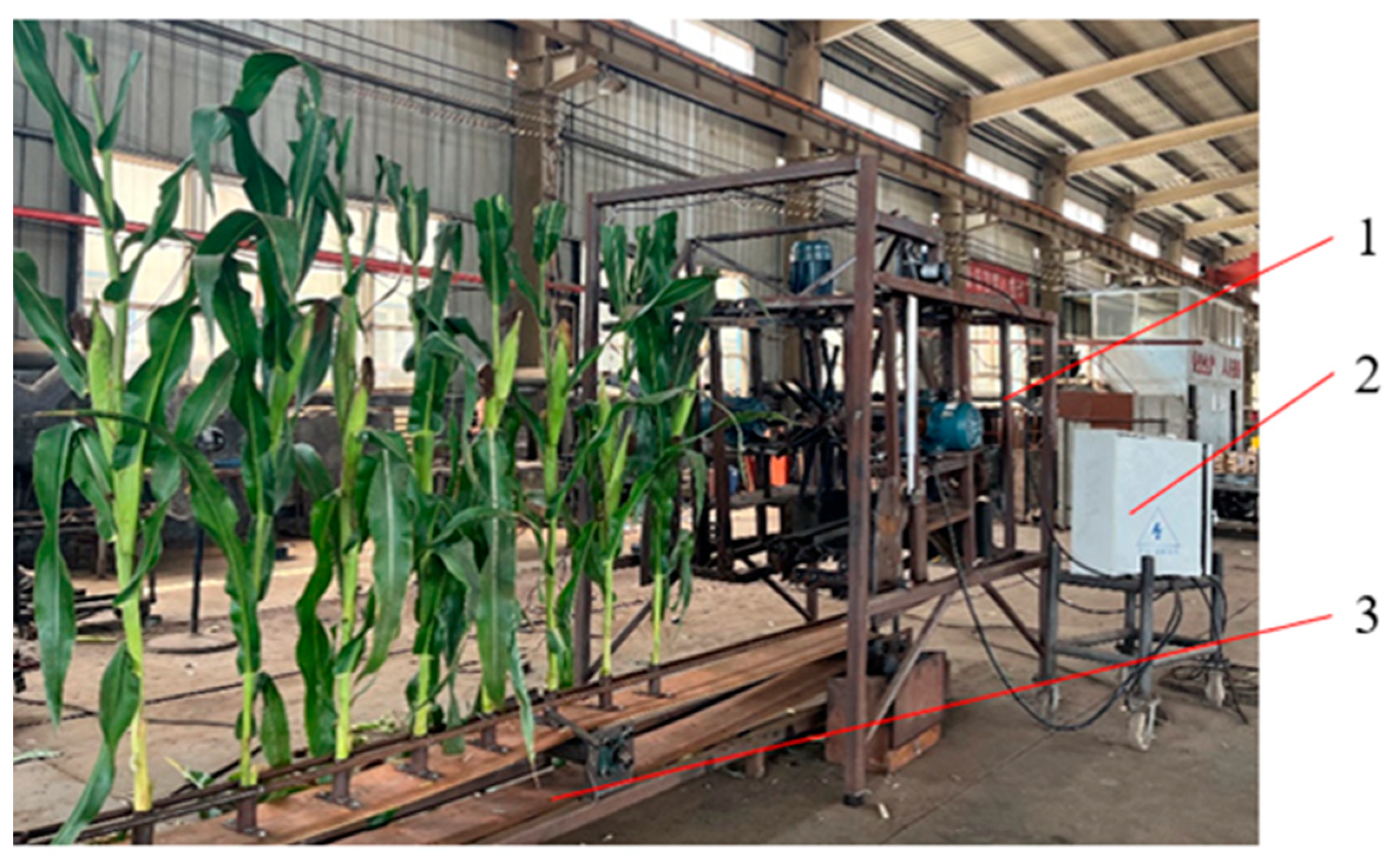
3.1. Fresh Corn Clamping and Breaking Device Test Bench

The directional clamping device in the fresh corn clamping and breaking device needs to have good stable clamping ability of the corn stem, to avoid excessive changes in the posture of the corn plant that may affect the breaking effect; the ear-breaking device requires a stable ear-breaking operation path, a certain degree of wear resistance and flexibility, and an efficient harvesting effect. According to the operational requirements of the fresh corn clamping and breaking device, a test bench for the fresh corn clamping and breaking device was designed, which mainly consists of a directional clamping and conveying mechanism, a breaking mechanism, and a stem pretreatment mechanism, as shown in Figure 10. The entire test bench is powered by electricity, and its specific structural parameters are listed in Table 3.

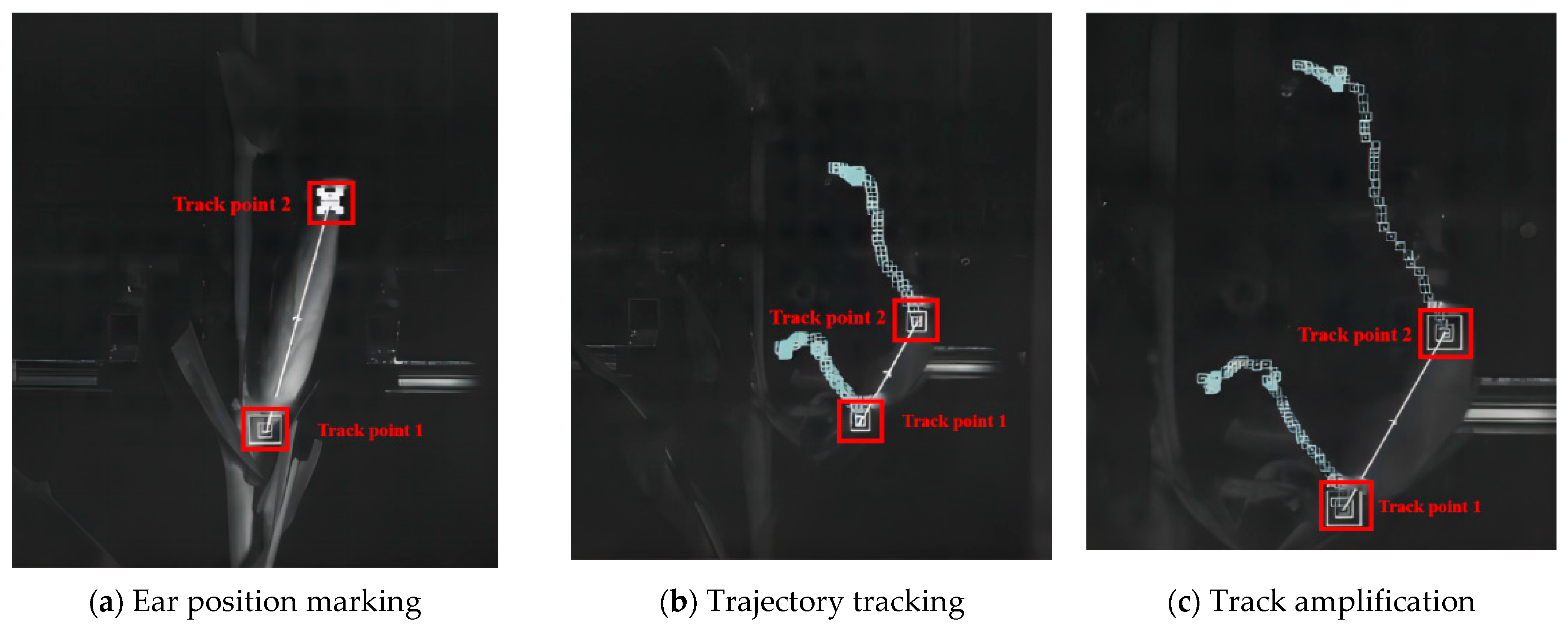
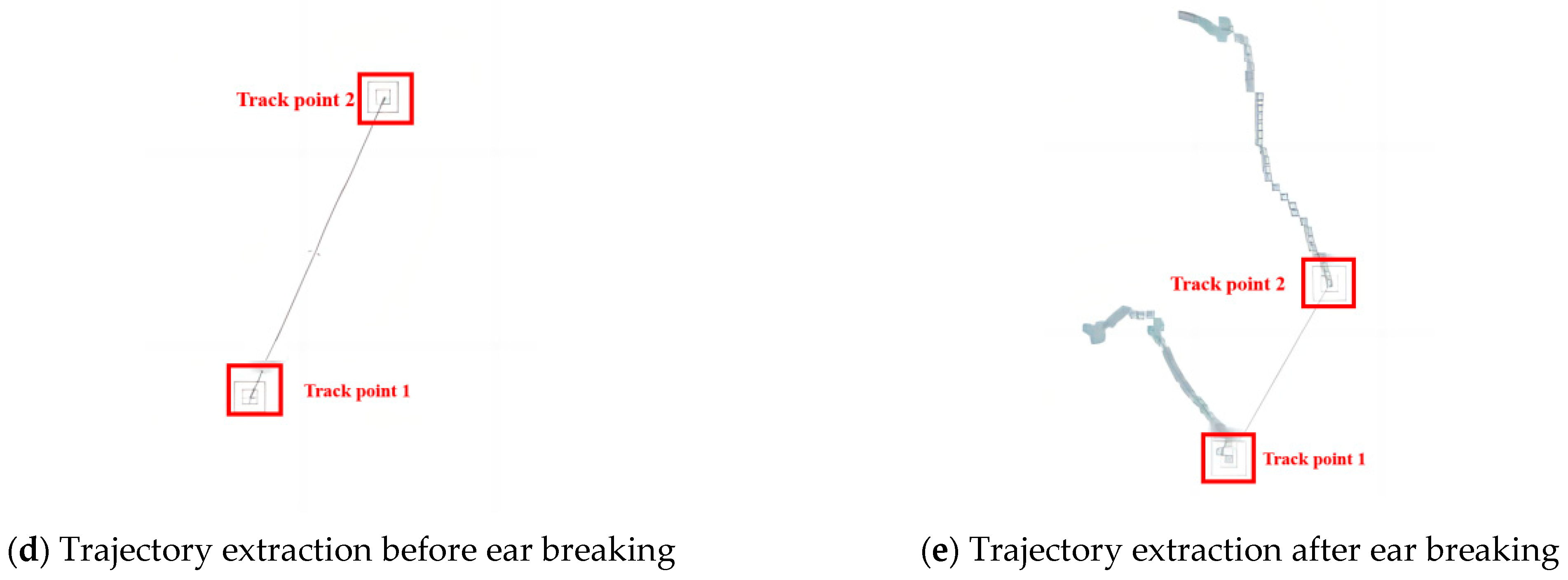
3.2. Tracking of Ears Movement Trajectory during Breaking

The process was theoretically verified using the directional clamping corn ear-breaking device test bench. High-speed photography technology was used to collect images of the trajectory changes of the ears being picked during the ear-breaking process. Later, motion-tracking software (Adobe After Effects 2021) was used to mark the position of the ears and track its motion trajectory [23], determining the contact situation of ears falling onto the collection board (Figure 11).
We tracked the motion trajectory through the ear-breaking process and used Adobe After Effects 2021 software to mark the bottom and top of the ear, as shown in Figure 12: the ear-breaking finger acts on the middle of the ear, and the stem has a certain bending strength. During the application of the ear-breaking force, the ear-breaking force did not reach the maximum bending force of the stem, resulting in a small degree of bending of the stem. Therefore, in the actual ear-breaking process, breaking the ear refers to sliding from the middle of the ear to the connection between the stem and the stem. During this process, the ear is affected by its own self-weight and breaking forces, and the displacement of the top changes quickly. It can achieve effective breaking of the ear using the combined force of its own gravity and breaking force. The actual operation and virtual simulation results are not significantly different, meeting the finite element and virtual simulation analysis of fresh corn breaking. The device design can thus be deemed reasonable.

3.3. Bench Test

3.3.1. Protocol

The experiments of gripping and breaking ears of fresh corn were conducted on a self-designed and constructed breaking ears test bench. As shown in Figure 13, the overall system adopts three-phase motor control (model: YX3-100L-6, manufacturer: Shanghai Dashu Motor Co., Ltd., Shanghai, China). By adjusting the output power of the frequency converter (model: CDI-EM60G1R5S2B, manufacturer: Hangzhou Delixi Frequency Converter Co., Ltd., Hangzhou, China), the operating parameters of each mechanism were controlled. After each mechanism had stabilized and was running smoothly, the test was started. The directional movement of fresh corn plants fixed on the feeding device simulated the relative movement of machinery and plants during harvesting operations.
The experimental material is fresh corn from the Wannuo 2018 variety, and the moisture content of fresh corn ears needs to be measured before the experiment. Moisture is used mainly to measure the moisture content of materials [27]. The measurement method is the constant temperature drying method. Five fresh corn plants are randomly selected from each point in the measurement area according to the five-point sampling method, and the mass q of the seeds is measured. The weight of the seeds is not less than 50 g. The temperature of the moisture meter is adjusted to 105 ± 2 °C, and each part of the material is placed in the test box. The material is dried in the tray for 5 h until the mass is constant, as shown in Figure 14. The mass q′ of each part is measured at this time, and the formula for calculating water content is shown in Equation (15):
Q 1 = q q q × 100 %
In the equation, Q1 is the moisture content of fresh corn ears, %; q is the quality before drying, g; q′ is the quality after drying, g.
The average moisture content of the ears measured in the experiment was 67.23%, which meets the harvest period standard. Corn plants with intact appearance, no sagging ears, and good growth conditions were selected as the experimental material. The experimental process used the quadratic regression orthogonal rotation combination method and Design Expert 8.0.6 software to determine the orthogonal coding values of three factors and five levels, as shown in Table 4.
To ensure the accuracy of the test results, each group of experiments was conducted three times, and 10 plants were harvested at a time. The overall operation of the device was stable, and there were no blockages. The test results of measuring the target factors using the constructed bench test are summarized in Table 5.

3.3.2. Test Indicators

The target factors for selecting experimental indicators include the ear damage rate and the ear impurity rate. To ensure the accuracy of measurement data, fresh corn planting parameters were measured in the field, and the number of plants per mu (the mu is a Chinese measure of land area, with 15 mu being equivalent to one hectare) was calculated. The target factors for testing 30 plants were converted into the rate of damage and harvest impurity rate per mu of fresh corn plants. The formula for calculating the number of ears per mu is as follows:
S = 667 ÷ ( l h l z ) j s
In the formula, S is the yield per mu of the ears, piece; lh is the average row spacing, cm; lz is the average plant spacing, cm; js is the ears setting rate, %.
Referring to the agricultural machinery promotion appraisal [20] (the specified indicators for ears harvesting in the technical conditions of fresh corn harvesters), it is required that the impurity content of fresh corn ears should be ≤2%, and the damage rate of fresh corn should be ≤4% for sweet corn; for glutinous corn and sweet glutinous corn, a value of ≤2% is acceptable.
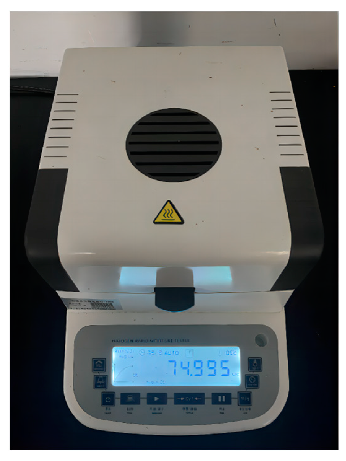
  • Due to the high moisture content of fresh corn, threshing measurement is not applicable. Therefore, after collecting all ears in the grain box and removing the bracts, the condition of each ear being damaged by the machine was checked, and the total number of grains and the number of damaged grains (with obvious cracks and peels) were calculated according to the following formula:
    Z s = W s W q × 100 %
In the formula, Zs is the grain damage rate, %; Ws is the number of damaged grains, piece; Wq is the total number of ears and grains, piece.
II.
In the area of measurement, this research collected the harvested grain from the grain bin, weighed the total mass and the mass of impurities (including stems and leaves), and calculated the impurity content as follows:
G n = W n W p × 100 %
In the formula, Gn is the ears impurity content, %; Wn is the quality of debris, g; Wp is the total mass of grain harvested in the grain tank, g.

4. Results

Based on bench test data, regression analysis was conducted using Design Expert 8.0.6 data analysis software [28] to obtain regression equations for ear damage rate R1 and harvest impurity rate R2, and their significance was tested [29].

4.1. Analysis of the Impact of Ear Damage Rate

4.1.1. Multiple Regression Analysis of Ear Damage Rate

Based on the analysis of experimental data and multiple regression analysis, an analysis of variance was conducted on the rate of ear damage (Table 6). The primary and secondary order of the interaction between factors is as follows: X2, X2×3, X12, X1, X1×3, X3, X22, X1×2, X32.
Among them, the rate of rotation of the ear-breaking wheel X2, the rotational speed of the ear-breaking wheel X2×3, and the machine forward speed X2×3. The secondary term X12 of the clamping feeding speed has a very significant impact on the ear damage rate R1 (p < 0.01); the clamping feeding speed X1, the interaction term X1×3 between the clamping feeding speed and the machine forward speed, the machine forward speed X3, and the secondary term X22 of the ear-breaking wheel speed have a significant impact on the ear damage rate R1 (0.01 < p < 0.05). The clamping feeding speed and the rate of rotation of the ear-breaking wheel X1×2, and the quadratic term X32 of the machine forward speed have no significant impact on the ear damage rate R1 (0.1 < p). The interaction terms of the insignificant terms are regressed to the sum of squares and degrees of freedom, and the residual term is included. Continuing with the analysis of variance, the regression equation for the influence of various factors on the ear damage rate R1 is:
R 1 = + 2.940 5.063 X 1 0.007 X 2 + 3.779 X 3 + 1.849 X 1 X 3 0.086 X 2 X 3 + 0.871 X 1 2 + 0.0006 X 2 2
According to the mismatch in the above equation, p = 0.5296, so it is insignificant, indicating that there are no other main factors affecting the experimental indicators. There is a significant quadratic relationship between the experimental indicators and the experimental factors [27].

4.1.2. Response Surface Analysis of Ear Damage Rate

Response surface analysis of the effects of interaction factors on the rate of ear damage was conducted using Design Expert 8.0.6 data analysis software. The experimental data were processed to obtain support for the significant and significant interaction between the feeding speed X1, the rate of rotation X2 of the ear-breaking wheel, and the machine forward speed X3 on the rate of damage to the ears, as shown in Figure 15.
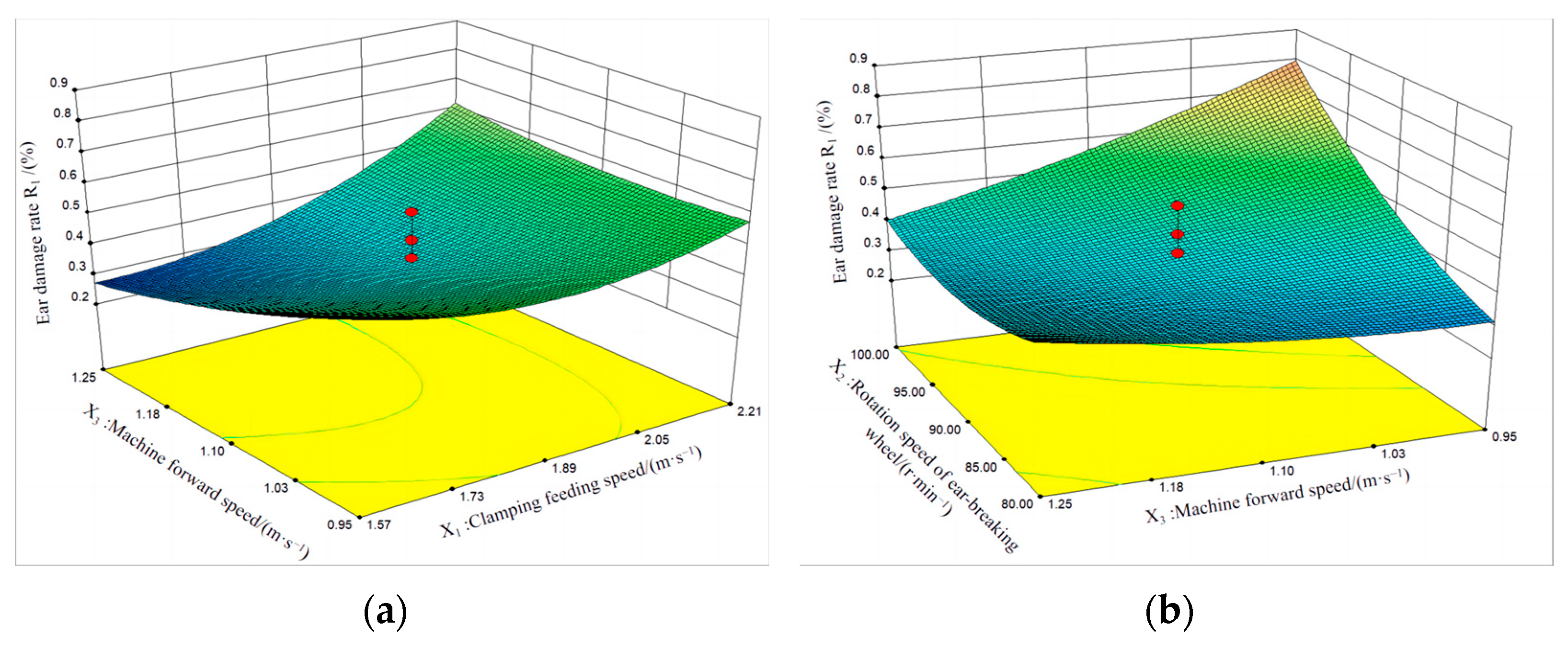
  • For the ear breakage rate R1, when the speed of the ear-breaking wheel X2 = 90 rpm, the interaction between the clamping feeding speed and the machine forward speed is shown in Figure 15a.
When the clamping feeding speed is constant, the ear breakage rate R1 gradually decreases with the increase in the machine’s forward speed.
As the machine’s forward speed increases, the overall tilt of the fresh corn plant decreases. The ear-breaking force generated by the rotation of the ear-breaking finger is a fixed value, and the effective breaking force acting on the ear of the fruit increases. The number of effective breaking operations increases, resulting in a decrease in the value of the ear damage rate R1.
When the machine advances at a certain speed, the rate of damage R1 gradually increases with the increase in the clamping feeding speed.
As the clamping feeding speed increases, the overall tilt angle of the fresh corn plant gradually increases. The increase in tilt angle reduces the effective number of times the ear-breaking wheel is applied to the ear, and the decrease in ear breaking force is likely to increase the bending force on the plant, leading to the inability to effectively pick the ear. This phenomenon may be attributed to the short clamping time actually applied to the ear.
That is to say, compared to the influence of the forward speed of the machine, when the speed of the ear-breaking wheel is constant, the clamping feeding speed is the main factor affecting the ear breakage rate R1.
II.
For the ear breakage rate R1, when the directional clamping feeding speed X1 = 1.59 m/s, the interaction between the ear-breaking wheel speed and the machine forward speed is as shown in Figure 15b.
When the machine advances at a certain speed, the ear damage rate R1 gradually increases with the increase in the rate of rotation of the ear-breaking wheel.
As the rate of rotation of the ear-breaking wheel increases, the force exerted by the ear-breaking wheel on the corn ear gradually increases. Due to the high moisture content of the grains, the smaller compressive strength is not sufficient to withstand the impact force exerted by the ear-breaking finger per unit area, resulting in an increase in the ear damage rate R1.
When the rate of rotation of the ear-breaking wheel is constant, the ear breakage rate R1 tends to decrease with the increase in the machine’s forward speed.
This may be because as the front speed increases, the overall tilt angle of the fresh corn plant gradually decreases during this process, and the effective number of ear breaking times caused by the ear-breaking wheel on the corn ears increases, resulting in an increase in the number of ear breaking times of the device and a decrease in the ear damage rate R1.
This means that compared to the influence of the forward speed of the machine, the rotational speed of the ear-breaking wheel is the main factor affecting the ear breakage rate R1 when the clamping feeding speed is constant.

4.2. Analysis of the Impact of Impurity Rate in Harvest

4.2.1. Multiple Regression Analysis of Impurity Rate in Harvest

Based on the analysis of experimental data and multiple regression analysis, the variance of the impurity content in the harvest was analyzed (Table 7). The primary and secondary order of the interaction between factors is: X1, X3, X32, X12, X2, X1×2, X2×3, X1×3, X22.
Among them, the clamping feeding speed X1, the machine forward speed X3, and the machine forward speed secondary term X32 have a significant impact on the harvest impurity content R2 (p < 0.01); the secondary term of clamping feeding speed X12, the rate of rotation of the ear-breaking wheel X2, the interaction term of clamping feeding speed and ear-breaking wheel speed X1×2, the interaction term of ear-breaking wheel speed and machine forward speed X2×3, the interaction term of clamping feeding speed and machine forward speed X1×3, and the secondary term of ear-breaking wheel speed X22 have a significant impact on the yield impurity rate R2 (0.01 < p < 0.05). There are no insignificant factors in the yield impurity rate, so an analysis of variance was conducted on the overall factors, the regression equation for the impact of each factor on the yield impurity rate R2 can be obtained as follows:
R 2 = + 23.6232 4.4796 X 1 0.2494 X 2 10.6688 X 3 + 0.0336 X 1 X 2 2.0313 X 1 X 3 + 0.0683 X 2 X 3 + 0.8564 X 1 2 + 0.0007 X 2 2 + 4.1333 X 3 2
From the mismatch of the above regression equation, p = 0.4004, so it is insignificant, indicating that there are no other main factors affecting the experimental indicators. There is a significant quadratic relationship between the experimental indicators and the experimental factors.

4.2.2. Response Surface Analysis of Impurity Rate in Harvest

The experimental data were processed using Design Expert 8.0.6 data analysis software to obtain the significant and significant interaction between the clamping feeding speed X1, the rate of rotation X2 of the ear-breaking wheel, and the machine forward speed X3 on the yield impurity rate. The response surfaces of the experimental factor indicators are shown in Figure 16, respectively.
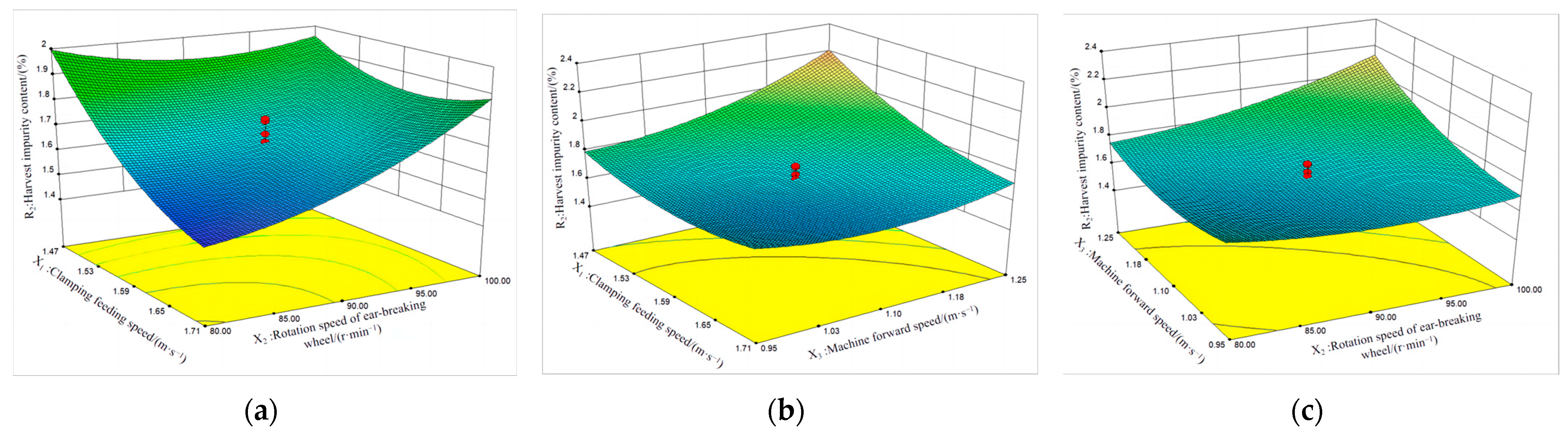
  • For the impurity content R2 of the harvest, when the machine advances at a speed X3 of 1.10 m/s, the interaction between the clamping feeding speed and the speed of the breaking wheel is shown in Figure 16a.
When the clamping feeding speed is constant, the impurity content R2 in the harvest gradually increases with the increase in the rate of rotation of the ear-breaking wheel.
This may be because as the rotational speed of the ear-breaking wheel increases, the rotational speed of the ear-breaking finger also correspondingly increases. The number of times the stems and leaves of fresh corn plants are subjected to the action of the ear-breaking finger increases, and the likelihood of the stems and leaves breaking increases. The proportion of broken stems and leaves to the harvest impurity rate increases, leading to an increase in the harvest impurity rate R2.
When the rate of rotation of the ear-breaking wheel is constant, the impurity content R2 in the harvest shows a decreasing trend with the increase in the clamping feeding speed.
This may be due to the increase in clamping feeding speed and the increase in stem inclination, resulting in a decrease in the contact time between the plant stem and the force of the ear-breaking finger and a decrease in the amount of stem and leaf falling, resulting in a decrease in the harvest impurity content R2.
That is to say, compared to the influence of clamping feeding speed, the rotational speed of the ear-breaking wheel is the main factor affecting the harvest impurity rate R2 when the machine’s forward speed is constant.
II.
For the harvest impurity content R2, when the rate of rotation of the ear-breaking wheel X2 is 90 rpm, the interaction between the clamping feeding speed and the machine forward speed is as shown in Figure 16b.
When the machine advances at a certain speed, the impurity content R2 in the harvest gradually decreases with the increase in the clamping feeding speed.
This may be due to the increase in clamping feeding speed and the inclination of the stem, which reduces the impact force on the stem after the breaking of the ear by the breaking finger. As a result, the degree of damage to the stem and leaves decreases, resulting in a decrease in the impurity rate R2 of the harvest.
When the clamping feeding speed is constant, the impurity content R2 in the harvest gradually increases with the increase in the forward speed of the machine.
This may be due to the increase in the forward speed of the machine, which increases the feeding amount of fresh corn plants and the number of interactions between fresh corn plants. The ear-breaking finger acts on the intertwined stems and leaves, and the area of action applied by the ear-breaking finger on the stems and leaves increases, increasing the possibility of stem and leaf breakage or damage, thereby increasing the impurity content R2 in the harvest.
That is to say, compared to the influence of clamping feeding speed, the forward speed of the machine is the main factor affecting the impurity rate R2 of the harvest when the rotational speed of the ear-breaking wheel is constant.
III.
For the impurity content R2 of the harvest, when the clamping feeding speed X1 is 1.59 m/s, the interaction between the speed of the breaking wheel and the forward speed of the machine is as shown in Figure 16c.
When the forward speed of the machine is constant, the impurity content R2 in the harvest gradually increases with the increase in the rate of rotation of the ear-breaking wheel.
This may be due to the increase in rotational speed of the ear-breaking wheel, which increases the number of times and impact force that the ear-breaking finger acts on fresh corn plants. The instantaneous impulse acting on the stems and leaves is larger, increasing the degree of damage to the stems and leaves, and thus increasing the impurity rate R2 in the harvest.
When the rate of rotation of the ear-breaking wheel is constant, the impurity content R2 in the harvest gradually increases with the increase in the machine’s forward speed.
This phenomenon is similar to the clamping feeding speed and machine forward speed as influencing factors when the speed of the ear-breaking wheel is constant.That is, when the clamping feeding speed and the rotating speed of the ear-breaking wheel are constant, the higher the forward speed of the machine, the more the feeding amount will cause the stems to intertwine with each other. When the ear-breaking finger applies force to it, the possibility of the stems and leaves breaking or damaging increases, resulting in an increase in the impurity content R2 of the harvest.
That is to say, compared to the influence of the rotational speed of the ear-breaking wheel, the forward speed of the machine is the main factor affecting the impurity content R2 of the harvest when the clamping feeding speed is constant.

4.3. Selection of Optimal Operation Parameters

Based on the response surface analysis of the ear damage rate and harvest impurity rate mentioned above, three regression models were solved using the optimization function in Design Expert 8.0.6 analysis software. According to the actual operating environment, performance requirements, and above analysis results of the fresh corn gripping and breaking device, the optimization and constraint conditions were selected as follows:
{ 1.35   m / s X 1 1.83   m / s 70.00   r p m X 2 110.00   r p m 0.85   m / s X 3 1.35   m / s min R 1 ( X 1 , X 2 , X 3 ) min R 2 ( X 1 , X 2 , X 3 ) 0.23 % R 1 0.85 % 1.49 % R 2 2.00 %
Based on the output values of certain parameters, various optimized combinations of mechanism operating parameters were obtained. Considering the stability of the overall operation of the harvesting device while ensuring the efficiency of the ear-breaking operation, the optimal combination of operation parameters was selected from multiple optimization results: a directional clamping feeding speed of 1.67 m/s, an ear-breaking wheel speed of 80 rpm, and a machine forward speed of 1.06 m/s were used: the corresponding average ear damage rate was 0.37%, and the average harvest impurity rate was 1.55%. Compared to the experimental data of the biomimetic ear picking mechanism designed by Guangqiang Zhu’s team [11], this parameter combination reduces the average ear damage rate by 0.51%.
Based on the theoretical operation parameters obtained from orthogonal experiments, the optimization results were experimentally verified to ensure the reliability of the parameter optimization results and the actual operation situation. The bench test validation results were taken as the average value, as displayed in Table 8. The actual experimental values and predicted values of ear damage rate and harvest impurity rate had errors of 0.2% and 0.32%, respectively. The error between the bench test measurement results and the orthogonal software analysis prediction results was relatively small. From this, the regression equation established in this study could be deemed reliable.

4.4. Discussion

From the analysis of the influencing factors of the two experimental indicators (ear damage rate R1 and harvest impurity rate R2) in Section 4.1 and Section 4.2 of this chapter, we found that the experiment still has some limitations.
In Section 4.1, we found in the analysis of R1 that the clamping feeding speed (X1) and the breaking wheel speed (X2) may be the two main factors (both will increase the value of R1), and the order of influence is X2, X1, X3. As shown in Table 6, the p-value of X2 is 0.01, which is a very significant impact, while the p-value of X3 and X1 is greater than 0.01, which is a significant impact.An increase in the value of X3 will result in a decrease in the value of the R1 test indicator, which is the result we hope to achieve. However, within the range of its influence, the forward speed of the machine (X3) is only taken as a certain value within the range of 0.85–1.35 m/s, which has certain limitations.
In addition, X2 accounts for a significant proportion of the impact on R1, which means that the value of R1 increases. This may be because the impact force applied by the ear-breaking finger is more likely to cause damage to the ear compared to the bending force on the ear when the clamping device is in contact. Because the moisture content of fruit ears is high, their compressive strength is low. However, this experiment did not investigate the range within which the compressive strength of the ears and the impact force generated by the breaking fingers were generated in the experiment.
In Section 4.2, where R2 may have more influencing factors, but its main influencing factors are similar to Section 4.1, namely X1, X2, and X3. The order of influence of these three is X1, X3, X2. (As shown in Table 7, p-values of X1 and X3 ≤ 0.01 are extremely significant effects; p-values of X2 > 0.01 are significant effects.)
X1 has a higher proportion of influence in multiple regression analysis, but the influence value of X3 is not significantly different from X1, and the feedback categories generated by the two on experimental indicators are also not the same. X1 will reduce the value of R2, while X3 will increase the value of R2. What we hope to see is that X1 can reduce the value of the experimental indicator R2.
Both X2 and X3 increase the value of R2, but the influence of X3 is relatively large. This may be because as the value of X3 increases, excessive feeding leads to the entanglement of stems and leaves, increasing the likelihood of stem and leaf breakage or damage. In contrast, when the value of X2 increases, the number of times the ear-breaking value acts on the stems and leaves increases, and the breakage of the stems and leaves is not as obvious as the phenomenon of intertwining between the stems. The specific value of stem and leaf breakage was not studied in this experiment.
Finally, the operation of the ear-picking device in this article is in a flexible ear-picking state. For the case of a rigid ear-picking state, no comparative experiment was conducted.

5. Conclusions

This article verifies the feasibility of the fresh corn ear-picking device through bench tests and analyzes the effects of various factors on the yield of ear damage and impurity content through orthogonal experiments of three factors and five levels.
  • Based on theoretical calculations and single-factor experiments, the effective operating speed range of each mechanism to ensure efficient harvesting operations was determined. Second, gradient partitioning of its parameters was performed using Design Expert 8.0.6 data analysis software, and orthogonal experimental parameter combinations were designed for testing and measurement.
After analyzing the experimental data and multiple regression analysis, it was found that the main and secondary order of the impact on the damage rate of fresh corn ears is as follows: the rotation speed of the ear-breaking wheel, the interaction term between the rotation speed of the ear-breaking wheel and the machine forward speed, the secondary term of the clamping feeding speed, the clamping feeding speed, the interaction term between the clamping feeding speed and the machine forward speed, the machine forward speed, and the secondary term of the ear-breaking wheel speed. The interaction term between the clamping feeding speed and the rotational speed of the ear-breaking wheel, as well as the quadratic term of the machine forward speed, have no significant impact on the ear breakage rate R1. The most obvious factor is the rotational speed of the ear-breaking wheel, which is the same as other types of ear-picking mechanisms for the rate of ear damage. However, due to the buffering effect of the flexible ear-breaking finger, the force change of the ear is relatively gentle.
After analyzing the experimental data and multiple regression analysis, it was found that the primary and secondary order of the impact of harvest impurity rate on the damage rate of fresh corn ears was as follows: clamping feeding speed, machine forward speed, machine forward speed quadratic term, clamping feeding speed quadratic term, ear-breaking wheel speed, interaction term between clamping feeding speed and ear-breaking wheel speed, interaction term between ear-breaking wheel speed and machine forward speed, and interaction term between ear-breaking wheel speed and machine forward speed The interaction term between the support feeding speed and the forward speed of the machine, as well as the quadratic term of the rotation speed of the ear-breaking wheel, do not have insignificant factors in the impurity content of the harvest. The most obvious factor is the clamping feeding speed, mainly due to the frequency of posture changes of fresh corn plants, which offsets the impact of the ear-breaking wheel on the plants.
The optimal operating parameter ratio obtained from the bench test is as follows: clamping feeding speed 1.67 m/s, breaking wheel speed 80 r/min, and machine forward speed 1.06 m/s. In the bench test, it was found that actively applying the breaking force through the flexible picking mechanism can effectively reduce the crushing rate of fruit ears and also solve the problem of blockage during mechanical harvesting.
II.
In order to ensure the reliability and stability of the fresh corn harvester, it is necessary to optimize the structural parameters of the harvester after conducting corresponding stem collection device design experiments. At the same time, it is necessary to optimize the material of the outer rubber of the ear-breaking finger to ensure the reliability of the ear-breaking mechanism. At the same time, to ensure the rationality of the header structure design, structural design and testing of the stem collection device will be carried out in the later stage based on this foundation.
III.
During the design and bench test of the fresh corn clamping and breaking device, the main objective was to study and test the damage rate and impurity content of corn harvest ears. The theoretical calculation and optimization of the device’s power consumption were not conducted. In the later stage, optimization design and improvement will be carried out based on the power consumption requirements of the harvesting device to meet the operational requirements of the fresh corn harvesting device.
IV.
During the experiment of breaking ears of fresh corn, data statistics were conducted on the damage rate and impurity content of the fresh corn harvest. The breaking device designed in this article effectively reduced the damage rate and impurity content compared to other types of fresh corn picking devices. Among them, during the picking experiment, the damage rate of each group of operating parameters was less than 1%, which was 1% lower than the industry indicator’s 2% damage rate. Due to the ear-picking device, the impurity content is mainly manifested as the breakage of fresh corn plant leaves. Therefore, the impurity content is selected within 2% to seek the optimal parameter ratio to meet the standard of mechanized corn harvesting operation.

Author Contributions

Conceptualization, X.H. and X.F.; methodology, H.Z. and X.H.; investigation, X.F., H.Z. and X.H.; writing—original draft preparation, X.H., X.F. and H.Z.; writing—review and editing, W.W., Z.Q. and J.S.; visualization, B.C. and W.W.; funding acquisition, X.H. and H.Z. All authors have read and agreed to the published version of the manuscript.

Funding

This research was funded by Henan Province Modern Agricultural Industry Technology System Corn Whole-Process Mechanization Special Project (HARS-22-02-G4).

Institutional Review Board Statement

Not applicable.

Informed Consent Statement

Not applicable.

Data Availability Statement

The data used to support the findings of this study are available from the corresponding author upon request.

Acknowledgments

The authors would like to appreciate the reviewers who provided helpful suggestions for this article.

Conflicts of Interest

The authors declare no conflict of interest.

References

  1. Kamonporn, S.D.; Ketthaisong, K.L. Bioactive, antioxidant and enzyme activity changes in frozen, cooked, mini, super-sweet corn (Zea mays L. saccharata ‘Naulthong’). J. Food Compos. Anal. 2015, 44, 1–9. [Google Scholar]
  2. Wang, Y.; Zhang, C. Current status and suggestions for the development of corn harvesting machinery. Agric. Eng. 2013, 3, 34–36. [Google Scholar]
  3. Shinners, K.J.; Adsit, G.S.; Binversie, B.N. Single–pass, split–stream harvest of corn and stover. Trans. ASABE 2007, 50, 355–363. [Google Scholar] [CrossRef]
  4. Hou, C.; Dong, Y.; Liu, C.G. Current situation and quality analysis of China’s corn harvester industry. Agric. Eng. 2019, 9, 20–25. [Google Scholar]
  5. Xin, S.; Zhao, W.; Dai, F. Design of crawler type corn combine harvester with full film double ridge and trench sowing in arid areas. Trans. Chin. Soc. Agric. Eng. 2019, 35, 1–11. [Google Scholar]
  6. Cui, T.; Liu, J.; Zhang, D. Design and test of a hybrid operating mechanism for harvesting and straw crushing. Trans. Chin. Soc. Agric. Mach. 2012, 43, 95–100. [Google Scholar]
  7. Hou, S.; Wang, X.; Ji, Z. Experiments on the influence of corn straw morphological combinations on timely no-tillage sowing soil temperature and moisture in cold regions. Agriculture 2022, 12, 1425. [Google Scholar] [CrossRef]
  8. Rovira-Más, F.; Han, S.; Wei, J. Autonomous guidance of a corn harvester using stereo vision. Agric. Eng. Int. CIGR J. 2007. Available online: https://cigrjournal.org/index.php/Ejounral/article/view/944 (accessed on 23 July 2023).
  9. Liu, Y.; Yang, R.; Wu, X. Design of ear picking device for corn harvesters in residential areas. J. Agric. Mech. Res. 2021, 43, 103–106+138. [Google Scholar]
  10. Wang, X.; Geng, L.; Li, X. Design and experiment of low-injury picking test table for fresh-eating maize. Agric. Eng. 2017, 7, 68–71. [Google Scholar]
  11. Zhu, G.; Li, T.; Zhou, F. Design and test of a biomimetic ear picking device for fresh corn. J. JiLin Univ. 2023, 53, 1231–1244. [Google Scholar]
  12. Zhang, L.; Li, Q. Test on ear breaking speed and power consumption of bionic corn ear breaking device. Trans. Chin. Soc. Agric. Eng. 2015, 31, 9–14. [Google Scholar]
  13. Chen, M.; Cheng, X.; Jia, X.; Zhang, L.; Li, Q. Optimization of structure and operation parameters of bionic hand ear breaking corn harvesting device. Trans. Chin. Soc. Agric. Eng. 2018, 34, 15–22. [Google Scholar]
  14. Wang, Y.; Zhang, Q.; Yu, L. The application status and prospects of corn ear picking equipment. J. Agric. Mech. Res. 2011, 33, 228–231. [Google Scholar]
  15. Rogovskii, I.L.; Liubarets, B.S.; Voinash, S.A. Research of diagnostic of combine harvesters at levels of hierarchical structure of systems and units of hydraulic system. J. Phys. Conf. Ser. 2020, 1679, 2–5. [Google Scholar] [CrossRef]
  16. Zhang, Z. Research and design of key components of fresh corn harvester. J. Farm Mach. Using Maint. 2021, 5, 14–16. [Google Scholar]
  17. Li, T.; Zhou, F.; Guan, X. Design and experiment on flexible low–loss fresh corn picking device. J. Int. Agric. Eng. J. 2019, 28, 2–4. [Google Scholar]
  18. Zhang, X.; Wu, P.; Wang, K. Design and test of 4YZT–2 self–propelled fresh corn harvester. Trans. Chin. Soc. Agric. Eng. 2019, 35, 1–9. [Google Scholar]
  19. Shahzad, M.W.; Burhan, M.; Ang, L. Energy–water–environment nexus underpinning future desalination sustainability. Desalination 2017, 413, 52–64. [Google Scholar] [CrossRef]
  20. GB/T21962–2020; S. Corn Harvesting Machinery. China Machinery Industry Federation: Beijing, China, 2020; pp. 4–5.
  21. Hao, W.; Liu, J.; Min, W. Changes of moistuer distribution and migration in fresh ear corn during storage. J. Integr. Agric. 2019, 18, 2644–2651. [Google Scholar]
  22. Xu, W.; Zhao, J.; Cui, X. The bionics design and analysis on device of corn picking with dragging and cutting stem. J. Agric. Mech. Res. 2018, 40, 81–86. [Google Scholar]
  23. Guan, X.; Li, T.; Zhou, F. Determination of bruise susceptibility of fresh corn to impact load by means of finite element method simulation. Postharvest Biol. Technol. 2023, 198, 2–9. [Google Scholar] [CrossRef]
  24. Lisowski, A.; Swiatek, K.; Klonowski, J. Movement of chopped material in the dischargespout of forage harvester with a flywheel chopping unit: Measurements using maize and numerical simulation. Biosyst. Eng. 2012, 111, 381–391. [Google Scholar] [CrossRef]
  25. Zhang, H.; Hu, R.; Kang, S. ANSYS 12.0 Finite Element Analysis from Introduction to Proficiency; Beijing Machinery Industury Press: Beijing, China, 2010. [Google Scholar]
  26. Liu, W.; Gao, W.; Yu, G. ANSYS 12.0 Classic; Beijing Electronic Industry Press: Beijing, China, 2010. [Google Scholar]
  27. Gorecki, J.; Lykowski, W. Influence of die land length on the maximum extrusion force and dry ice pellets density in ram extrusion process. Materials 2023, 16, 4281. [Google Scholar] [CrossRef] [PubMed]
  28. Ferreira, S.L.; Bruns, R.E.; Ferreira, H.S. Box–Behnken design: An alternative for the optimiazation of analytical methods. Anal. Chim. Acta 2007, 597, 179–186. [Google Scholar] [CrossRef] [PubMed]
  29. Geng, A.; Yang, J.; Zhang, J. Analysis of factors affecting mechanical damage of corn picking and harvesting. Trans. Chin. Soc. Agric. Eng. 2016, 32, 56–62. [Google Scholar]
Figure 1. Directional clamping corn straw breaking header. 1. Hydraulic motor. 2. Directional clamping mechanism. 3. Breaking mechanism. 4. Reel chain. 5. Stem pulling roller. 6. Stem cutting mechanism. 7. Header power input shaft. 8. Breaking mechanism power spindle. 9. Breaking transmission chain. 10. Pulling chain transmission shaft.
Agriculture 13 01506 g001
Figure 2. Structural diagram of directional clamping and conveying mechanism. 1. Active pulley. 2. Clamping belt. 3. Tensioning pulley. 4. Guide pulley. 5. Passive pulley.
Agriculture 13 01506 g002
Figure 3. Schematic diagram of plant inclination angle under clamping and conveying.
Agriculture 13 01506 g003
Figure 4. Stress analysis of ears.
Agriculture 13 01506 g004
Figure 5. Schematic diagram of ears breaking mechanism. 1. Flexible breaking finger. 2. Rotating wheel hub.
Agriculture 13 01506 g005
Figure 6. Static ear breaking interval. 1. Directional clamping mechanism. 2. Corn plants. 3. Fresh corn ears. 4. Breaking fingers.
Agriculture 13 01506 g006
Figure 7. The relative position of the ear-breaking finger and the ears. 1. Ear-breaking roller. 2. Corn plants.
Agriculture 13 01506 g007
Figure 8. Grid division of fresh corn plants.
Agriculture 13 01506 g008
Figure 9. Strain cloud diagram under vertical force.
Agriculture 13 01506 g009
Figure 10. Structure diagram of the test bench for the fresh corn clamping and breaking device. 1. Directional clamping mechanism. 2. Ear picking mechanism. 3. Inner frame. 4. Outer frame. 5. Lifting push rod. 6. Stem pretreatment mechanism. 7. Cutting mechanism.
Agriculture 13 01506 g010
Figure 11. Image collection during ear-breaking process. 1. Test bench. 2. Control box. 3. Display. 4. Feeding device. 5. High-speed camera.
Agriculture 13 01506 g011
Figure 12. Tracking and extraction of ear trajectory during ear-breaking process.
Agriculture 13 01506 g012aAgriculture 13 01506 g012b
Figure 13. Physical image of the test bench. 1. Test bench. 2. Control box. 3. Feeding device.
Agriculture 13 01506 g013
Figure 14. Measurement of grain moisture content.
Agriculture 13 01506 g014
Figure 15. Effect of the interaction of experimental factors on the rate of ear damage. (a) The interactive effect of the clamping feeding speed and machine forward speed on R1; (b) The interactive effect of the rotation speed of ear-breaking wheel and machine forward speed on R1.
Agriculture 13 01506 g015
Figure 16. Response surface of experimental factor interaction on the impurity content in harvest. (a) The interactive effect of clamping feeding speed and the rotation speed of ear-breaking wheel on R2; (b) The interactive effect of clamping feeding speed and machine forward speed on R2; (c) The interactive effect of the rotation speed of ear-breaking wheel and machine forward speed on R2.
Agriculture 13 01506 g016
Table 1. The physical characteristics of fresh corn.
BreedPositionAverage ValueBreedPositionAverage Value
Wannuo 2018Plant height2250 mmStanuo 41Plant height2310 mm
Ear height937 mmEar height1005 mm
Lower diameter of spike position28.5 mmLower diameter of spike position30.1 mm
Diameter at ear position19.3 mmDiameter at ear position21.7 mm
Diameter of the four nodes on the ear16.7 mmDiameter of the four nodes on the ear18.3 mm
Ear diameter at the large end52.3 mmEar diameter at the large end48.7 mm
Table 2. Model parameters of fresh corn plants.
Young’s Modulus (N·mm−2)Density (kg·mm−3)Poisson’s Ratio
3.67 × 1034.5 × 1070.33
Table 3. Test bench size parameters.
PositionSize Parameter
Overall dimensions of the test bench1800 mm × 1300 mm × 2125 mm
Dimensions of lifting inner frame1120 mm × 1090 mm × 1180 mm
Directional clamping and conveying mechanism1000 mm × 400 mm
Rotation radius of ear-breaking mechanismr = 320 mm
Operation length of stem-pulling roller580 mm
Range of platform lifting angle0~40°
Table 4. Encoding of test factors.
Encoding ValuesFactor
Clamping Feeding Speed (m·s−1)Spinning Finger Rotation Speed (rpm)Forward Speed (m·s−1)
21.83110.001.35
11.71100.001.25
01.5990.001.10
−11.4780.000.95
−21.3570.000.85
Table 5. Test plan and results.
NumberFactorObjective Function
Clamping Feeding Speed
X1
Spinning Finger Rotation Speed
X2
Forward Speed
X3
Ear Damage Rate
R1
Harvest Impurity Content
R2
11.4780.000.950.471.92
21.7180.000.950.371.75
31.47100.000.950.821.73
41.71100.000.950.851.93
51.4780.001.250.522.14
61.7180.001.250.651.52
71.47100.001.250.232.30
81.71100.001.250.742.17
91.3990.001.100.482.29
101.8390.001.100.831.54
111.5970.001.100.311.73
121.59110.001.100.851.98
131.5990.000.850.641.72
141.5990.001.350.312.14
151.5990.001.100.371.76
161.5990.001.100.321.71
171.5990.001.100.241.68
181.5990.001.100.471.66
191.5990.001.100.561.49
201.5990.001.100.411.77
Table 6. Analysis of variance for ear damage rate.
ProjectSourceSum of SquaresFreedomMean SquareF Valuep Value
Damage ratemodel0.73/0.699/70.082/0.0997.70/7.880.018/0.0011
X10.098/0.0981/10.098/0.0989.29/7.870.0123/0.0159
X20.17/0.171/10.17/0.1716.37/13.860.0023/0.0029
X30.063/0.0631/10.063/0.0635.92/5.010.0353/0.0449
X1 X20.03310.0333.070.1102
X1 X30.063/0.0631/10.063/0.0635.96/5.040.0348/0.0444
X2 X30.13/0.131/10.13/0.1312.53/10.610.0054/0.0069
X120.12/0.121/10.12/0.1211.54/9.270.0068/0.0102
X220.062/0.0571/10.062/0.0575.85/4.580.0361/0.0535
X320.01210.0121.100.3190
residual0.11/0.1510/120.011/0.012
misfitting term0.042/0.0875/78.492 × 10−3/0.0120.67/0.980.6643/0.5296
pure error0.063/0.0635/50.013/0.013
total0.8419
Note: The diagonal line represents the analysis of variance for R1 after removing insignificant factors. p < 0.01 represents a highly significant impact, 0.01 ≤ p ≤ 0.05 represents a significant impact, and 0.05 ≤ p ≤ 0.1 represents a more significant impact.
Table 7. Analysis of variance of the impurity content in harvest.
ProjectSourceSum of SquaresFreedomMean SquareF Valuep Value
Impurity contentmodel1.0790.1210.070.0006
X10.2910.2924.430.0006
X20.1110.119.270.0124
X30.1710.1714.120.0037
X1 X20.09210.0927.860.0187
X1 X30.07610.0766.460.0293
X2 X30.08410.0847.140.0234
X120.1110.119.420.0119
X220.06410.0645.410.0423
X320.1210.1210.590.0087
residual0.12100.012
misfitting term0.06650.0131.270.4004
pure error0.05250.010
total1.1819
Note: p < 0.01 represents a highly significant impact, 0.01 ≤ p ≤ 0.05 represents a significant impact, and 0.05 ≤ p ≤ 0.1 represents a relatively significant impact.
Table 8. Statistical results: experimental validation.
Comparative Test VerificationEar Damage RateHarvest Impurity Content
Theoretical data0.37%1.55%
Actual test mean0.57%1.87%
Disclaimer/Publisher’s Note: The statements, opinions and data contained in all publications are solely those of the individual author(s) and contributor(s) and not of MDPI and/or the editor(s). MDPI and/or the editor(s) disclaim responsibility for any injury to people or property resulting from any ideas, methods, instructions or products referred to in the content.

