1. Introduction
Traditional ditching machines mainly include four types: the plow, disc, chain, and spiral types. They have the following characteristics and scopes of application: The plow ditcher is suitable for harsh farmland conditions but has low mechanical strength and low power output; the disc ditcher is suitable for southern farmlands, has high mechanical strength, and is more commonly used; the chain ditcher, which is suitable for digging deep and narrow ditches, has a good ditch shape and high efficiency and is often used for laying pipelines or cables; and the spiral ditcher has low resistance, has good operation quality, can throw soil and mix, and is often used for ditching and fertilizing in hilly and mountainous orchards [
1,
2,
3]. It can also loosen soil and cut roots at the same time, promote the circulation of hot water and fertilizer, stimulate the growth of new fine roots, enhance the absorption capacity, and improve the subsequent fertilization effect [
4,
5]. Compared with that for other types, the research on the spiral ditcher is relatively undeveloped. With the standardization and normalization of orchard agriculture, as well as the increasing shortage in the labor force, the demand for mechanized ditching is increasing, which has promoted the innovation and development of various new types of ditching machines. To improve upon the conventional spiral ditcher, this study designed a counter-rotating dual-axis spiral ditcher.
In recent years, to improve the level of mechanization in orchards, relevant experts have designed a variety of new spiral ditchers. These ditchers are based on traditional operation methods, but they have been innovated and optimized by adopting different spiral structures and working parameters to adapt to different soil environments and agronomic needs. For example, the 1KS60-35X orchard-type dual-spiral fertilizer applicator developed by Xiao Hongru et al. 2017 can perform the integrated operations of soil breaking with the front axle and of soil stirring and fertilizing with the rear axle, thus effectively saving time and resources and improving the operation efficiency [
6]. Ma Tie, Lin Jing, and Gao Wenying et al. designed a deep burial and returning machine for straw with a spiral ditching device and compared the advantages and disadvantages of single-spiral and dual-spiral structures; in addition, they drew on the principles of bionics to optimize the design of the spiral blade surface, enhanced the anti-blocking performance of the spiral blade, improved the adaptability of the spiral ditcher, and determined the optimal working parameters of the spiral ditcher through experiments [
7,
8]. Jiang Jianxin designed a dual-side spiral ditching device for small orchards that had two gears of operation speeds that could be flexibly adjusted according to the soil environment and agronomic needs, and they conducted a detailed design study on the structural parameters of the spiral cutter and the power parameters of the machine [
9].
The simulation of the process of the interaction between a cutter and soil is an effective research method that can greatly shorten the research and development time and save research costs through analysis. This is of great significance for the optimization of agricultural machinery [
10]. In recent years, discrete element simulation, which is a common simulation method, has been used by more and more scholars to study the interactions between soil and operation machinery. It provides a basis for the optimization of the structural and motion parameters of a cutter by analyzing the changes in the force state of the soil and cutter during operation [
11,
12]. For example, Wang Shaowei optimized a ditching cutter based on an inclined spiral ditcher that was developed by his research group for hilly orchards. He established a discrete element simulation model for analyzing the ditching power consumption and studied the law of the influence of the operation parameters on the ditching power consumption [
13]. Zang Jiajun et al. designed a curved ditching and mixing device based on an orchard straw-covering machine to realize the integration of ditching, fertilizing, and mixing operations. They conducted a discrete element simulation of the ditching and fertilizing processes to determine the optimal pitch and operation speed of the cutter [
14]. At present, there is still a lack of research on spiral ditchers. According to relevant studies, it was shown that an inclined shaft operation can effectively reduce the cutting power consumption of a cutter during operation [
15]. Therefore, it is necessary to further study spiral ditchers and optimize the power consumption and effects of their cutters during operation.
This study was aimed at the demands of ditching operations in hilly and mountainous orchards, the design of a counter-rotating dual-axis spiral ditcher, and the establishment of a discrete element model of the interaction of a spiral cutter and soil by taking the ditching qualification rate and operation power consumption as the test indicators. We used EDEM software for the analysis of the simulated experiments, explored the effects of the cutter’s structural and operation parameters on the ditching performance, and obtained the optimal combination of the structural and operation parameters for the cutter; finally, we verified the simulation results with a soil trough test, which proved the reliability of the simulation model and the rationality of the optimization scheme.
2. Materials and Methods
2.1. Design of the Overall Structure
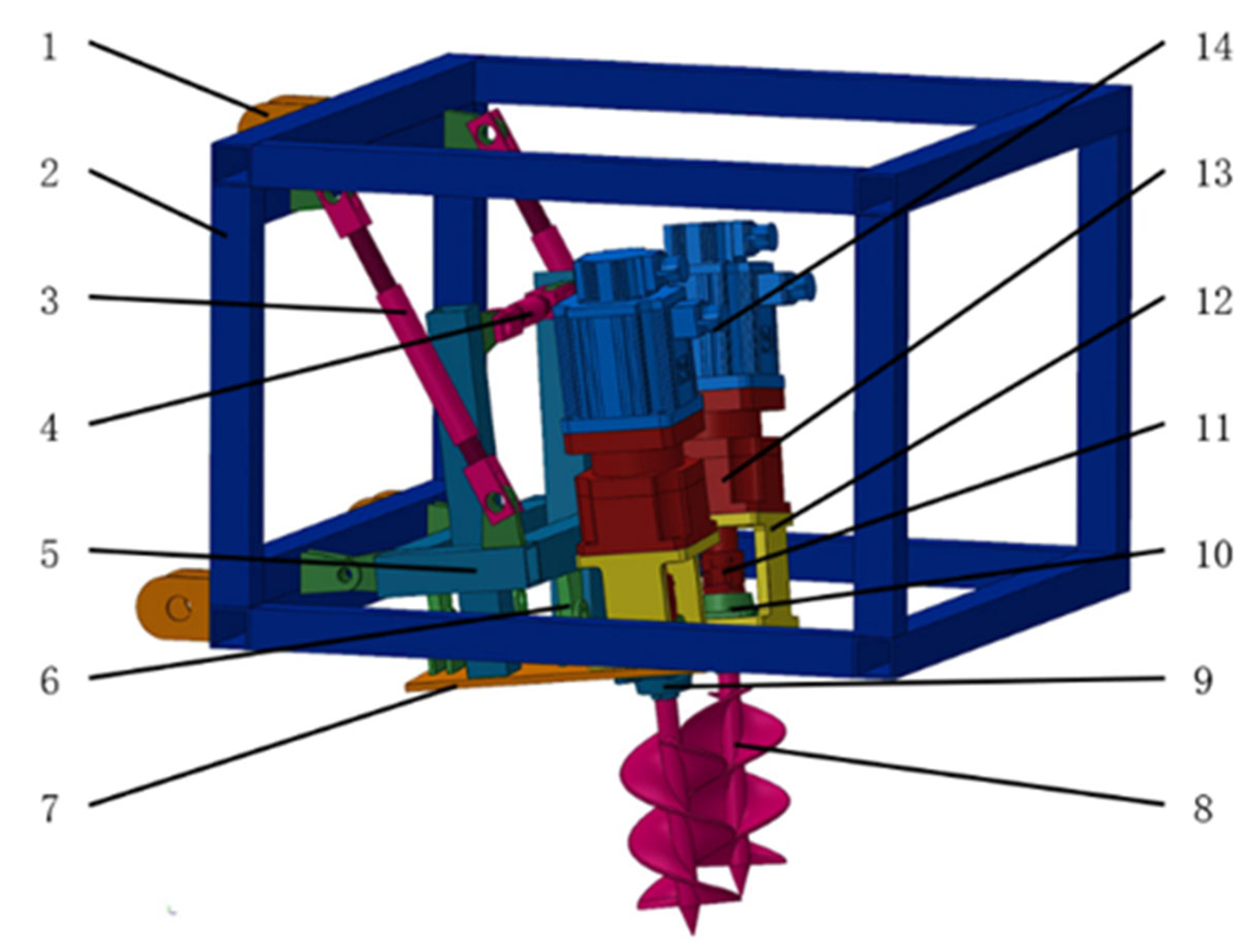
The main components of the spiral ditcher were a three-point suspension frame, limit pull rod, movable hinge, spiral cutter, drive motor, reducer, etc. A diagram of the structure is shown in
Figure 1. The machine was connected to a traction vehicle by a three-point suspension device. The power output from the motor was transmitted to the spiral cutter shaft through the reducer and a coupling to drive the cutter’s rotation. The motion parameters of the cutter could be precisely controlled by adjusting the output speed through the motor control box. The device was also able to control the ditching depth and width by adjusting the length of the limit pull rod on the frame, which changed the operating angle of the cutter. The operation depth and width of the ditcher could be flexibly adjusted according to the agronomic needs and field conditions in different operation environments. The ditching cutter consisted of a pair of double-blade spiral cutters with opposite helixes, for which a coaxial double-blade structure that could alleviate the problem of unbalanced force on the cutter shaft during rotation was adopted. During operation, the ditching cutter first completed the soil entry process; from top to bottom in the forward direction, the left cutter shaft rotated clockwise, and the right cutter shaft rotated counterclockwise; that is, they were arranged in counter-rotation.
The working principle was as follows: First, the output shaft of the motor drove the cutter shaft to rotate through the reducer, and it gradually lowered the cutter to cut into the soil. Then, when the cutter reached the predetermined trenching depth, the tractor moved forward and started trenching. The spiral blade continued to cut and throw out the soil at the rear end out of the trench. The spiral trencher was able to adjust the working angle of its trenching cutter according to the user’s needs to achieve the desired effect of adjusting its trenching depth and width. The trenching depth could be adjusted from 150 mm to 250 mm, and the trenching width could be adjusted from 150 mm to 200 mm. When the three-point suspension position remained unchanged, the depth of the operation could be changed by adjusting the length of the limit rod to change the angle between the tool axis and the horizontal plane. The relationships between the angle of the cutter shaft, the horizontal plane, and the working depth are shown in
Table 1.
2.2. Design of the Trenching Components
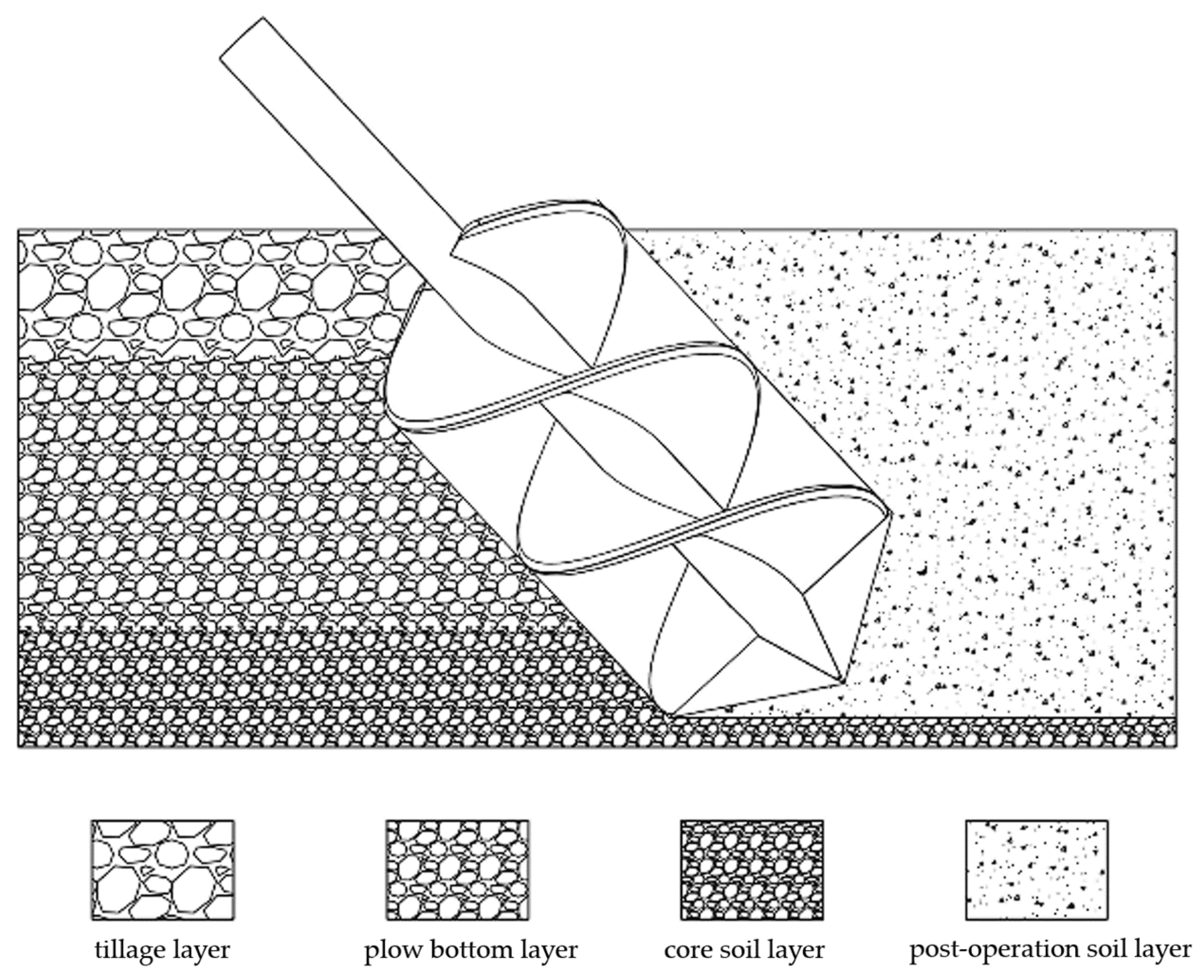
The spiral ditching tool used a motor to drive the spiral blade to rotate at a high speed, thus cutting the soil particles and making them move along the spiral’s direction. The soil particles were subjected to centrifugal force and moved to the outer edge of the spiral blade. At the same time, the ditch wall exerted friction on the soil particles, inhibiting them from rotating with the blade and causing them to rise along the spiral blade to the soil surface; then, they were thrown out of the ditch under the influence of centrifugal force. This method was able to effectively loosen the soil structure and improve the quality and efficiency of the operation [
16]. The device mainly consisted of a keyway connecting shaft, an inner spiral cylinder, a spiral blade, and a soil-drilling cone. The connecting shaft, inner spiral cylinder, and drill tips were welded into one piece; the spiral blades were welded symmetrically in four sections on the inner cylinder. According to previous design experience, a blade shaft diameter of 20 mm, a blade outer diameter of 100 mm, and a blade thickness of 3 mm were chosen. In order to enhance the strength of the blade and break through the hard soil of the bottom plow layer, heat treatment was required [
17].
The spiral blade is a key component of a soil-lifting machine, and its pitch type, number of threads, and installation method determine the quality of the soil-lifting effect [
18]. By comprehensively considering the processing difficulty and operation effects, this study finally adopted a fixed pitch blade for trial production. In order to optimize the soil-lifting amount and operation efficiency, an inclined double-shaft spiral cutter was adopted, which was installed in a trapezoidal shape to adapt to the trapezoidal cross-section of ditches in hilly mountain orchards. The specific parameters of the fixed pitch blade and double-thread spiral blade are shown in
Table 2, and their soil-lifting performance was tested and analyzed.
Figure 2 shows a schematic diagram of the cross-section of the ditching process.
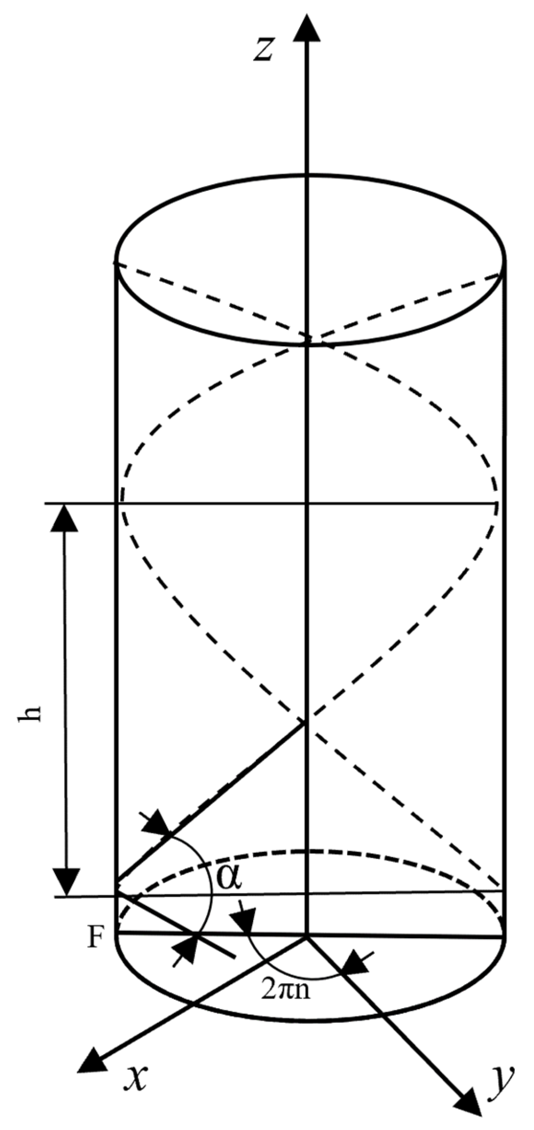
The spiral blade is a core component of a spiral ditching machine, and the shape of its spiral line determines the effect of its interaction with soil particles. The spiral line of a double-blade spiral cutter can be expressed by a hyperbolic spiral; that is, when any point L on the cylinder moves along the generatrix at a constant speed from bottom to top while the generatrix rotates around the central axis of the cylinder, its motion trajectory is a spiral line, as shown in
Figure 3. If the spiral line is flattened, it becomes a straight line on a plane. In the figure, the initial spiral angle corresponding to the starting point of the spiral line is α, and the height corresponding to the position of point L after the generatrix has turned n times is h. Such a spiral shape can allow a double-blade spiral cutter to more effectively cut soil particles during ditching and reduce the resistance of soil to the blade. The parameters of the spiral line can be optimized and adjusted according to different soil types and ditching operation requirements in order to achieve better ditching effects.
The spiral line equation of the double-spiral ditching tool is [
19]:
α is the initial angle of the helix (°), n is the number of turns of the helix, and l is the arc length (m) of the busbar.
By taking the derivative of
z, the tangent value of the helix angle at a certain point of the constant-pitch helix is:
By substituting the starting position of the helix,
,
,
, into Equation (4), the coefficient α of the quadratic term of the constant-pitch helix α is:
a is the initial angle (°) of the helix, and n is the number of turns of the helix.
2.3. Working Parameters of the Cutting Tool
During the trenching process, the effects of soil being cut and discharged out of the trench by the helical blade determine the quality and efficiency of trenching. The rotational speed of the cutting tool is an important factor affecting the trenching effect. If the trencher speed is too low, the soil will accumulate at the bottom of the trench, resulting in a reduction in the trench depth and width; if the speed is too high, the soil will be thrown too far, causing soil loss and backfilling difficulties. Therefore, according to the trenching conditions and requirements, an appropriate trencher speed should be selected. The calculation method for the rotational speed of the helical trenching tool is as follows [
20,
21,
22]:
In the formula, Fr is the dimensionless similarity criterion (determined by the trenching helix angle; the range of values is 2.5–4.5), and D is the outer diameter of the helical blade (m).
The helix pitch angle affects the trenching efficiency, and the helix pitch angle in this machine’s design was 15°. The relationship between the feed per revolution
S of the helical trencher and the angle
ξ (the value was 1°, and the range was 0.4°–1°) between the direction of motion of a point on the helical blade and the horizontal plane is given by the following formula:
ξ is the angle between the direction of motion of a point on the helical blade and the horizontal plane.
In order to cause the soil to be smoothly thrown out of the trench, when the helix pitch angle was 15° and the angle
ξ between the direction of motion of a point on the helical blade and the horizontal plane was 1°, the minimum value of the angle β between the soil’s direction of motion and the horizontal plane and the value of
Fr were obtained from the table; these were 15° and 3.86, respectively. By appropriately increasing β to 24°, the critical speed of the helical trencher could be calculated as 238 r·min
−1 [
23,
24,
25].
2.4. Establishment of the Simulation Model
This study used EDEM (DEM-Solutions, Edinburgh, UK, 2021) software to conduct the simulation experiments. By referencing the research of other scholars on the discrete element parameters of soil, a model that simulated the interaction between the tool and the soil was established [
26]. In order to cause the soil simulation to be closer to the characteristics of the sticky soil in Hunan, China, a Hertz–Mindlin model with bonding was selected, and bond connections were added between the soil particles to form a whole that could withstand tangential and normal displacements [
27,
28]. When it was subjected to a force that exceeded the preset maximum shear stress, the bonds broke, and the particles were treated as separate individuals by the system in order to continue the simulation. By adding bonds, the physical properties of the soil could be more realistically reflected. The model was suitable for simulating a broken working state and could be more intuitively used to observe the breaking effect of the tool on the soil [
29]. After the calculation was finished, the resistance of the tool in the forward process and the torque of the cutter roller in the soil could be directly analyzed by using the resulting data [
30], thus providing data support for the improvement of the working parameters of the tool and the optimization of the structural design.
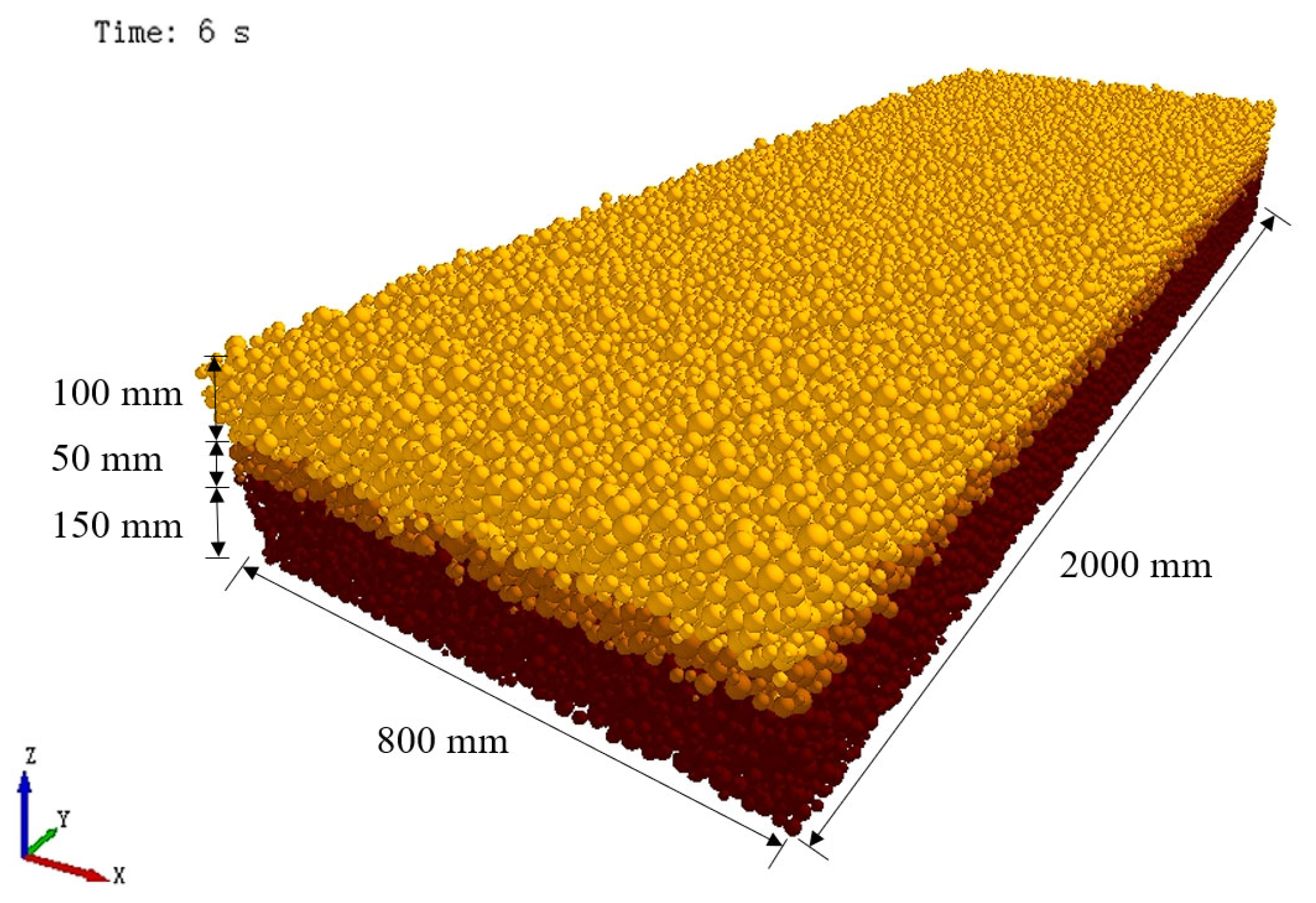
Based on the relevant literature, the physical parameters of both the soil particles and the tool were set in the preprocessing stage of the software. The soil had two types of density: the true density (the mass of soil per unit volume of solid particles) and the bulk density (the mass of soil per unit volume of the whole soil). For the same soil, the higher the compaction degree, the greater the bulk density. In order to simulate the actual soil, the soil model was divided into three layers: namely, the tillage layer, the plow bottom layer, and the core soil layer, with an increasing bulk density from top to bottom. The thickness of the tillage layer was about 10 cm, the thickness of the plow bottom layer was about 5 cm, and the thickness of the core soil layer was about 15 cm. In the modeling process, the setting of soil particles affected the quality and accuracy of the simulation calculations. Too large particles would cause distortion and an inability to reflect the actual physical process; too small particles would cause a sharp increase in the computer’s calculation time. Therefore, the size of the soil particles needed to be appropriately selected. Considering the performance of the equipment used in the simulation platform, a particle diameter of 8 mm was selected, and the material’s name was set as “soil” [
31,
32].
According to the above parameters, a virtual soil tank with dimensions of 2000 mm × 800 mm × 300 mm (length × width × depth) was established. The soil particles were spherical particles of a uniform size, and to reflect the state of different sizes of particles in the soil, the particles were generated in a form with a normal distribution. An initial velocity of 0.5 m/s was applied to the particle
Z-direction to promote falling compaction. The dynamic generation method was adopted for the creation of the particles, which took 3 s and generated 90,118 particles. Finally, by using the Analyst module, the simulation result file was output with a new file name, and this served as the virtual soil tank for the subsequent simulation experiments (see
Figure 4).
2.5. Experimental Scheme
This study adopted the discrete element simulation method to simulate the movement of the cutter through the soil tank and to explore the trenching performance of the spiral trenching tool. The simulation operation process is shown in
Figure 5.
Based on relevant design experience, the trenching performance was mainly affected by three factors—traction speed (A), cutter shaft speed (B), and trenching depth (C)—while keeping the field soil conditions constant. On this basis, a three-factor and three-level orthogonal experiment was designed, with the trenching depth qualification rate (Y1) and power consumption (Y2) as the experimental indicators; the L9(33) orthogonal table was used to arrange the experimental scheme.
Table 6 presents the experimental factor levels. This study used SPSS 27 software to perform an analysis of variance and a range analysis on the experimental data and to obtain the effect size and the optimal combination of the factor levels for the experimental indicators.
The calculation method for the trenching depth qualification rate is as follows:
In the formula, S1 is the trenching depth qualification rate (%), S0 is the actual trenching depth (cm), and S is the theoretical trenching depth (cm).
The power consumption of the trenching machine mainly included two parts: One part was the torque power for the cutter’s rotation, and the other part was the traction power for the advancement of the cutter. The sum of the two was the total power consumption of the trenching machine. In this study, the discrete element simulation method was used to numerically calculate and analyze the torque and resistance of the cutter while using different motion parameters.
A discrete element simulation of the torque and resistance of the trenching machine cutter was carried out to study its power consumption characteristics by using EDEM software. Because EDEM software cannot directly output the power consumption parameters, other methods were needed to calculate the power consumption. In this study, the postprocessing module Analyst Tree that was built into the software was used to export the torque and force data of the cutter during the simulation process, and the interval density of the data was set to 0.1 s to ensure their accuracy and continuity. Then, according to the set speed constant and the torque and force obtained from the simulation experiments, the power consumption formula was used to calculate the power consumption of the cutter. The motion trajectory of the cutter in the soil tank was simulated. The cutter rotated around the cutter shaft and moved at a constant speed along the direction of the
y-axis. In order to eliminate the non-steady-state influence before and after the cutter entered the soil tank, only the time period from when the cutter completely contacted the soil to when it left the soil was analyzed, which was 7.1 s–8.6 s, in order to reflect the actual cutting state of the cutter.
Figure 6 shows the effect of throwing soil on the border (left) and floating soil at the bottom of the ditch (right) after the operation.
Figure 7 shows examples of line charts of the torque and
y-axis force on the cutter shaft over time under the following conditions: traction speed = 0.05 m/s, speed = 440 rpm, and working depth = 25 cm.
The torque power consumption and traction power consumption of the tool were added, and the total power consumption of the trenching process was calculated:
In the formula, T is the torque (N·n) applied to the tool, and n is the rotational speed of the tool (r/min).
The calculation formula for the traction power consumption is:
In the formula, F is the resistance (N) applied to the tool, and v is the forward speed of the tool (m/s).
3. Discussion
3.1. Analysis of the Simulation Results
SPSS data processing software was used to analyze the experimental results, as shown in
Table 7 and
Table 8.
According to the results of the data analysis shown in
Table 7 and
Table 8, among the three experimental factors that affected the rate of the qualified trenching depth: traction speed, trenching depth, and cutter shaft speed, the traction speed and trenching depth had the most significant effects on the experimental results, while the effect of the cutter shaft speed was more significant. The importance of the experimental factors was in the following order: traction speed, trenching depth, and cutter shaft speed. The best combination was A1B2C1.
This study adopted an evaluation index based on the number of bond breakages between soil particles to analyze the soil fragmentation rate after the operation. Bonds were used as a measure of the force of interactions between soil particles. When the spiral trenching machine applied cutting force to the soil, the bonding bond was damaged, and the number of bonding bond connections showed a stable decreasing trend, leading to the separation and fragmentation of soil particles. Therefore, the change in bond number reflected the change in the soil fragmentation rate. A statistical function was set up in the postprocessing module of the software to count the number of bonds that were generated and broken, and graphs of the corresponding curves were drawn. By comparing the curve graphs generated with different combinations of the working parameters, the soil fragmentation by the spiral trencher could be analyzed and compared. The statistical results are shown in
Figure 8.
By comparing the line chart of bond changes under the combination of the three working parameters, combined with the working area of the tool in the soil tank, it could be calculated that the average crushing rate of the trenching tool in the effective operation range of the soil tank was 66%, which met the quality requirements of NYT 740-2003 field trenching machinery, and the number of bonding bonds did not change with time. Therefore, in order to improve the test efficiency, the number of bonding bonds reduced within 1 m of the tool was used as the operating effect index.
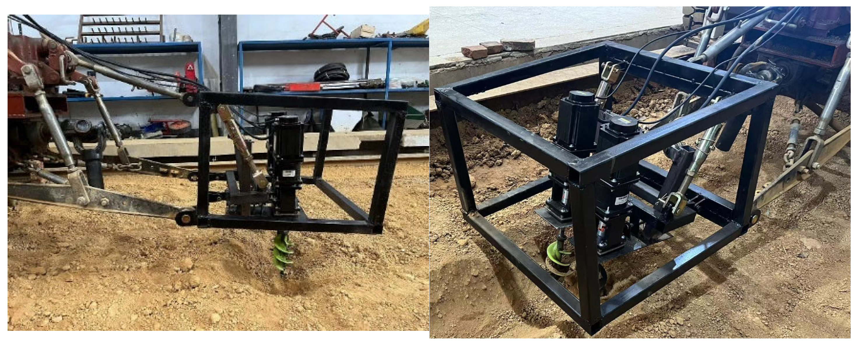
3.2. Soil Groove Test Conditions
The soil groove test bench of the Agricultural Training Center of Hunan Agricultural University was selected as the test site for the spiral trenching test. In the soil groove test bench, the spiral trencher was installed on a TCC electric four-wheel drive soil groove test car by using three-point suspension. The main parameters of the test car were as follows: a soil groove length of 30 m, a width of 2.95 m, a drive motor input voltage of 380 V, and a rated power of 30 kW; a stepless speed regulation could be achieved. The power output motor was a Taiwan Fuda frequency conversion motor with a base frequency of 50 Hz, and a stepless speed regulation was used by means of an ORS2000S 30kW frequency converter.
According to the simulation results, the initial motor selection was optimized, and the DC brushless motor model 110BL140-430 was chosen as the driving power source for the trenching rotary motion. Its rated power was 1500 W, its rated voltage was 48 V, its rated current was 42 A, its rated speed was 3000 rpm, and its rated torque was 14.4 Nm. In order to measure the influence of the spiral trencher on the soil properties, the following testing equipment was used: a M-85 soil density meter, a TTJSD-750-IV soil compaction meter, a WKT-M1 soil moisture meter, a WT-CF series high-precision electronic scale, a push–pull tester (HP-50k), a steel frame tape measure, and a meter ruler. The tester used in the experiment is shown in
Figure 9.
3.3. Soil Tank Test Plan
In order to verify the correctness of the simulation model, a spiral trenching test was carried out in the experimental soil tank of Hunan Agricultural University. The size of the soil tank selected for the experiment was 6 m × 2 m × 0.6 m, and it was filled with compacted soil, as shown in
Figure 10. Before the experiment, the density and moisture content of the soil were measured by using a WT-CF series high-precision electronic scale and WKT-M1 soil moisture meter, respectively, and the measurement results were 2712 kg/m
3 and 26.25%; the average hardness of 0–30 cm of soil was measured with an SC900 soil hardness tester, and this value was 0.61 MPa. According to a comparison, the parameters of the soil in the experimental field were basically consistent with those of the simulated soil.
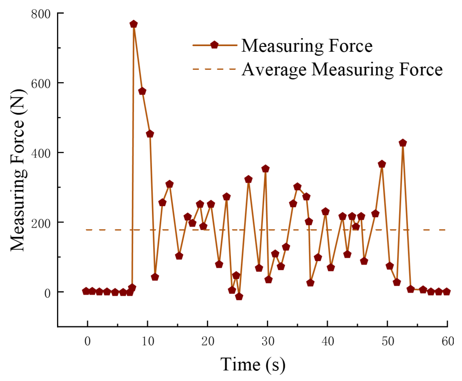
We selected an inclination angle of 24° and an operation speed of 0.05 m/s as the optimal parameter combination according to the working conditions in the soil tank verification experiment. We attached the push–pull force tester between the tractor and the trenching tool to measure the traction resistance—that is, the magnitude of the force applied to the tool shaft in the simulation test. In each experiment, the machine advanced a distance of no less than 1 m to ensure the stability of the trenching. A total of five experiments were conducted for this study, and the average value was taken as the experimental result. The results measured by the tensile tester are shown in
Figure 11 and
Table 9. The error between the average value of the measured force and the simulation test results was 11%, which was close to the simulation test results.
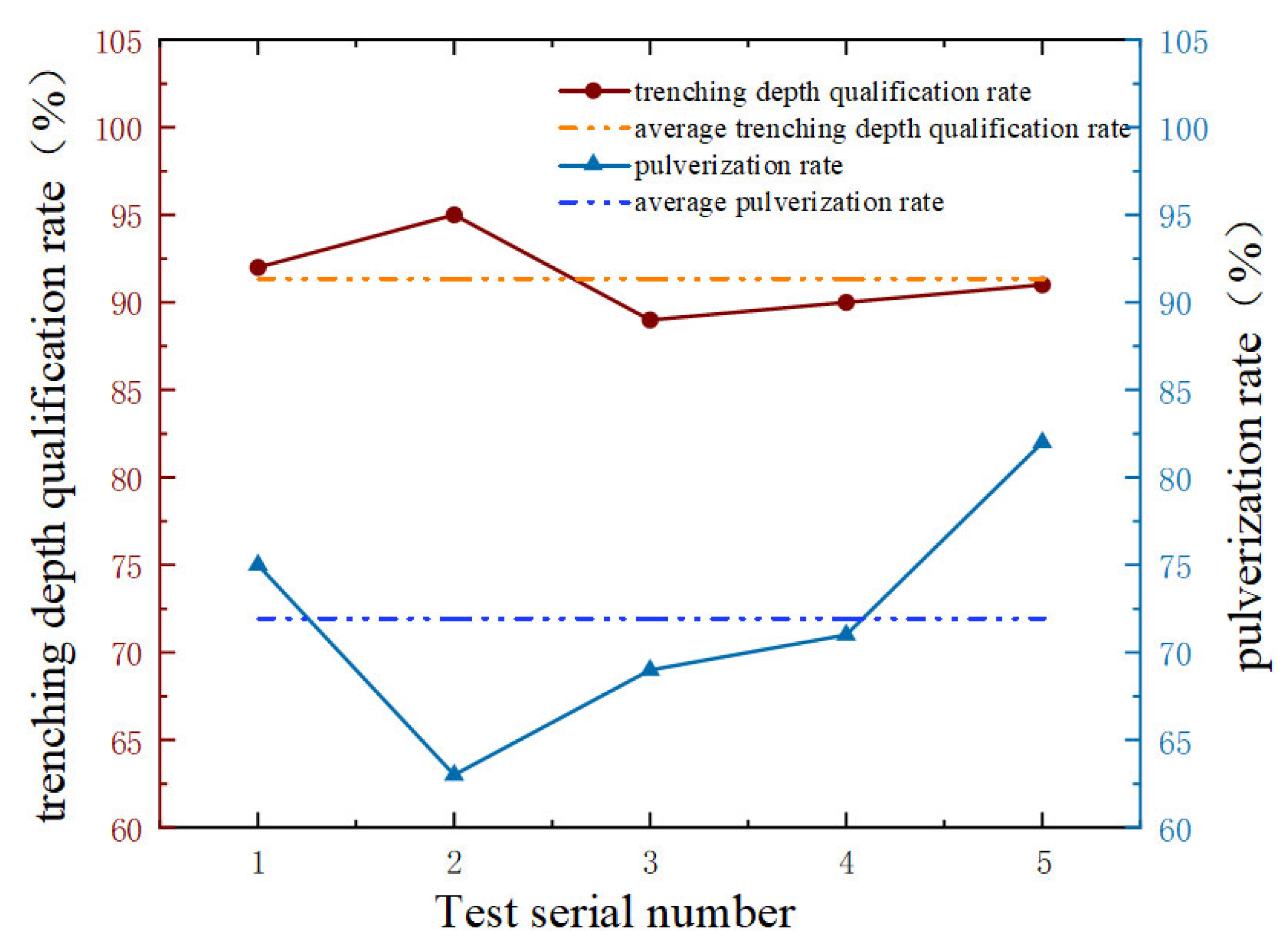
In the soil tank test, priority was given to the qualified rate of trenching and the rate of soil fragmentation as the evaluation indicators. In order to evaluate the trenching quality, the trenching depth was measured every 200 mm along the machine’s forward direction, and the trenching qualification rate was calculated. The trenching qualification rate was the proportion where the ratio of the actual trenching depth to the predetermined trenching depth reached more than 90%.
Five detection areas in the soil tank with an identical area were randomly selected after the operation, and the pulverization rate of the machine’s operation was evaluated. The area of each detection area was 50 mm × 50 mm. In each detection area, the mass of all soil blocks with the longest side not exceeding 4 cm was measured, and the percentage of the total mass in all soil blocks in that detection area was calculated; this was used as the pulverization rate of that detection area. The higher the pulverization rate, the better the soil-breaking effect of the trencher.
Figure 12 and
Table 10 show a map of the distribution of the results of the soil tank verification test.
Based on the measurements and calculations of the soil-crushing rate in the soil trough test field, this study also collected data on the trenching depth, trench shape, floating soil thickness at the bottom of the trench, and ridge width. By comparing the test results with the local agronomic requirements and relevant standards, the following conclusions were drawn: The average trenching depth in the soil trough test was 23.53 cm, which met the needs of agricultural production, and there was a small fluctuation in the trenching depth. The average trench width was 26.8 cm, the average trench bottom width was 18.4 cm, the average pass rate was 91.4%, and the trench shape was that of a ladder-shaped rectangle. The floating soil thickness at the bottom of the trench was 0.1 (trenching depth), the width consistency coefficient was 82%, and the trencher had good stability and accuracy during the walking process. The average soil fragmentation rate was 72%, which met the requirements of NY/T740-2003 and GB/T 5262-2008. The machine had a good soil-crushing effect, which was conducive to the improvement of soil aeration.
The results of the simulation experiment were compared to the results of the soil tank verification experiment. It was found that, under the same parameter conditions, they had high consistency, indicating that the actual trenching performance was close to the simulated trenching performance, thus proving the correctness of the simulation experiment. This showed that the motion analysis of the trenching tool and the simulation method used in this study were reliable and reasonable.
4. Conclusions
A new type of counter-rotating dual-axis spiral trenching tool was designed to meet the trenching demands for orchards in hilly and mountainous areas, and its working performance and influencing factors were analyzed and optimized in depth. The trenching tool was able to adapt to different agronomic requirements and operating environments, and it was able to achieve the effects of soil crushing, turning, and stirring while trenching, which was conducive to improving the interactions of water, fertilizer, and heat in the soil. We drew the following conclusions from the analysis of the simulation experiments in combination with the soil tank verification experiments.
A three-dimensional dynamic model of the soil particles and the tool was established by using the discrete element method, and the process of interaction between the soil and the tool during trenching was simulated. The motion trajectory of the soil particles and the laws of variation in the torque, force, and power of the tool were analyzed.
Based on the model created with the discrete element method, the parameters of the trencher, such as the spiral pitch angle; pitch; and motion parameters, including the forward speed, rotation speed, and working depth, were analyzed and optimized by using a sensitivity analysis and design optimization. We obtained an optimal parameter combination that improved the working efficiency and stability of the trencher.
By using an orthogonal test method, the effects of the forward speed, trenching depth, trencher rotation speed, and other parameters on the trenching depth qualification rate, total power consumption, and other performance parameters were studied. We found the optimal level and degree of influence. It was found that the forward speed was the most important factor that affected the working performance of the trencher, followed by the trenching rotation speed and depth.
While using the optimal parameter combination, a soil tank test was carried out to measure the actual working performance of the trenching tool, and the results were compared to those of the simulation test. The reliability and validity of the simulation test results were verified.
In this study, we analyzed and discussed the principle and method of the double-spiral trenching operation, which provides some reference and support for the design and technology involved so that related trenching operations can be used to better complete their objectives and tasks.


