Article

Working Mechanism and Parameter Optimization of a Crushing and Impurity Removal Device for Liquid Manure

1
Nanjing Institute of Agricultural Mechanization, Ministry of Agriculture and Rural Affairs, Nanjing 210014, China
2
Graduate School, Chinese Academy of Agricultural Sciences, Beijing 100083, China
*
Authors to whom correspondence should be addressed.
Agriculture 2022, 12(8), 1228; https://doi.org/10.3390/agriculture12081228
Submission received: 28 July 2022 / Revised: 11 August 2022 / Accepted: 12 August 2022 / Published: 15 August 2022

Abstract

:
Aiming to solve the problems of easy clogging and high energy consumption of multi-way fertilization devices for liquid manure, a crushing and impurity removal device for liquid manure was designed by combining the physical characteristics of liquid manure and impurities, and building the corresponding test bench. The proposed device could crush flexible impurities such as straw and filoplume and intercept hard impurities with high density. The main structural parameters of the device were determined according to the survey analysis and the theoretical design. The influences of cutter head shape, cutter edge angle, cutter shaft speed, and cutting clearance on the disqualification rate and energy consumption of straw crushing were obtained by a single-factor experiment. Furthermore, the Box–Behnken central composite design method of the response surface was employed to investigate the effects of the cutter shaft speed, cutting clearance, and cutter edge angle on the disqualification rate and energy consumption of straw crushing. In addition, the working parameters of the device were optimized by employing the response surface method. On this basis, the mathematical relationship model among the disqualification rate, energy consumption, and all influencing factors was established. The results show that the optimal combination of working parameters includes a cutter shaft speed of 312 r/min, a cutting clearance of 1.4 mm, and a cutter edge angle of 45°. From the prediction model, the predicted failure rate was 4.15%, and the predicted energy consumption was 47.53 J. The verification experiment was then performed under the optimal combination of working parameters. The obtained disqualification rate was 4.08% and the energy consumption was 47.56 J, which met the design and work requirements.

1. Introduction

According to statistics, China’s annual production of livestock and poultry waste is about 4 × 10⁹ tons [1]. Livestock and poultry waste produce massive amounts of organic manure liquid after anaerobic or aerobic treatment. Before discharge, the organic manure liquid should comply with discharge standards through biochemical treatment, which leads to a high cost. If the organic manure liquid cannot be treated in a timely manner, it will cause non-point source pollution [2]. On the other hand, livestock and poultry manure liquid are rich in organic substances that are beneficial to soil improvement and small molecular humus that can be easily absorbed by plants. Moreover, livestock and poultry manure liquid can be used for the improvement of soil fertility. To effectively control the environmental pollution caused by livestock manure and improve soil quality, China has developed a series of policies and action plans in recent years to promote the use of livestock manure and fertilizers [3].
Liquid manure has a high viscosity and complex composition and contains a lot of animal hair, straw fiber, and small amounts of stones, metals, plastics, and other impurities. It is easy to block and damage the distributor in the process of fertilization. In recent years, there have been some studies on the front-end filtration of biogas slurry [4]. Duran-Ros et al. conducted filtration and backwashing tests using three filter systems, namely, mesh filter, lamination filter, and mesh-lamination composite filter, under 300 and 500 KPa, respectively. The results showed that there was no significant difference between turbidity, particle concentration, and total suspended solids (TSS) after filtration by the three filtration systems. However, the lamination filter used more water for backwashing [5]. The laminated structure designed by Cui et al. could form composite channels with filtration accuracies of 60 mesh and 120 mesh. The results pointed out that the lamination filter with composite channels had lower water head loss compared to the lamination filter with normal linear channels of 120 mesh [6]. In a connected study, Yang et al. placed four mutually perpendicular meshes inside a sand tank to design a new-type integrated filtration device. After analyzing the flow field by using CFD numerical simulation technology, the authors found that the integrated filtration device could reduce the head loss by 38.5%, leading to better hydraulic performance, better filtration effect, and longer operation time [7].
The above filtering and impurity removal devices are mainly used for the pretreatment of biogas slurry at the front-end of the biogas slurry drip irrigation system. The small flow channels of the drip irrigation system are easily blocked by biogas slurry impurities, which can affect the uniformity of fertilization and its service life [8]. Hence, the key technology is to remove impurities in biogas slurry [9,10,11] However, the solid part of livestock and poultry manure liquid also contains a higher nutritional mechanism, and it would cause a waste of resources if the solid part were removed. In addition, the ammonia and nitrogen nutrient elements in liquid manure are volatile, and the direct spraying of liquid manure will pollute the environment. Therefore, it is an established trend to greatly reduce ammonia volatilization by adopting a multiple ditching fertilization method. Zhao developed a wheel-type liquid manure deep displacement machine. There were six liquid diversion hole openers distributed on the hole opening fertilization wheels. When the diversion hole opener was inserted into the soil, it was controlled by the end CAM switch and opened to inject the high-pressure liquid manure rapidly along the diversion hole opener into the soil. When the amount of liquid manure corresponding to the fertilizing location of the hole opener met the requirements, the end CAM control switch was closed. This marks the completion of one fertilization process [12]. Yuan designed a rotor-blocking distributor with five outlets. Through experimental analysis, it was shown that when the rotation speed of the distributor rotor was 90 r/min, the fluid in the distributor complies well with the designed functions in theoretical analysis. Considering a distribution device with five channels as an investigation case [13], Liu simulated and optimized the pulse-type bog fertilizer blocking-preventing and distribution device employing the water hammer pressure and water hammer vibration theories. The reported results highlighted that the rotating shaft speed was 37.8 rad/s, the cone taper was 11/6, and the front inclination angle of the baffle θ was greater than 40°. Carrying out an optimization process on the device, the flow rate of the outlets increased by 0.2 m/s and the pressure difference increased by 0.01 MPa, with increasing rates of 4.0% and 5.5%, respectively [14].
Nevertheless, the distributor mentioned above does not have the function of crushing and removing impurities. As a result, the fertilizing hose is easily blocked and the fertilizing device could easily be damaged. In this study, a crushing and impurity removal device was designed, developed, and installed on the front of the distributor to solve the problems of easy blocking and damage of multi-channel fertilization systems, based on the concept of all livestock and poultry waste returning to the field. The device can intercept impurities such as sand and gravel in the liquid manure and store them in the storage compartment of the crushing and impurity removal device. In addition, the organic matter such as hair and straw can be crushed and follow the flow passage into fertilizing channels, which provides favorable conditions for the subsequent uniform distribution and smooth application of liquid manure. This will help achieve the goal of fully returning to the field. Moreover, a single-factor test and a multi-factor response surface test were conducted to establish the mathematical model combining the crushing and impurity removal factors and the evaluation indexes. The model will aid in optimizing the process and finding the best combination of working parameters, which can provide a baseline reference for the development of devices for liquid manure returning to the field.

2. Materials and Methods

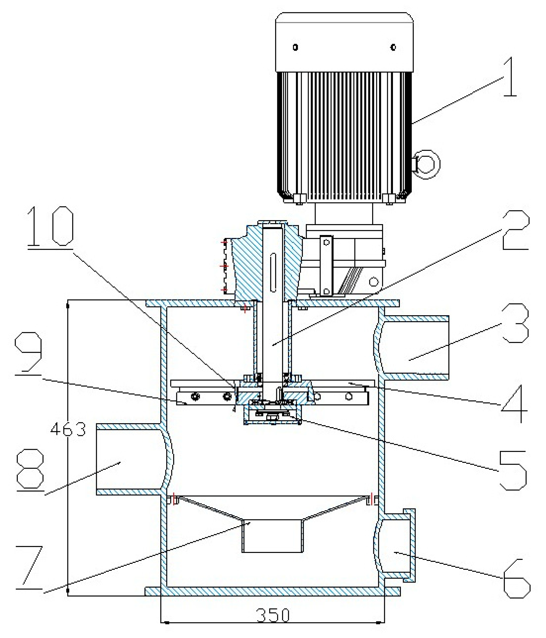
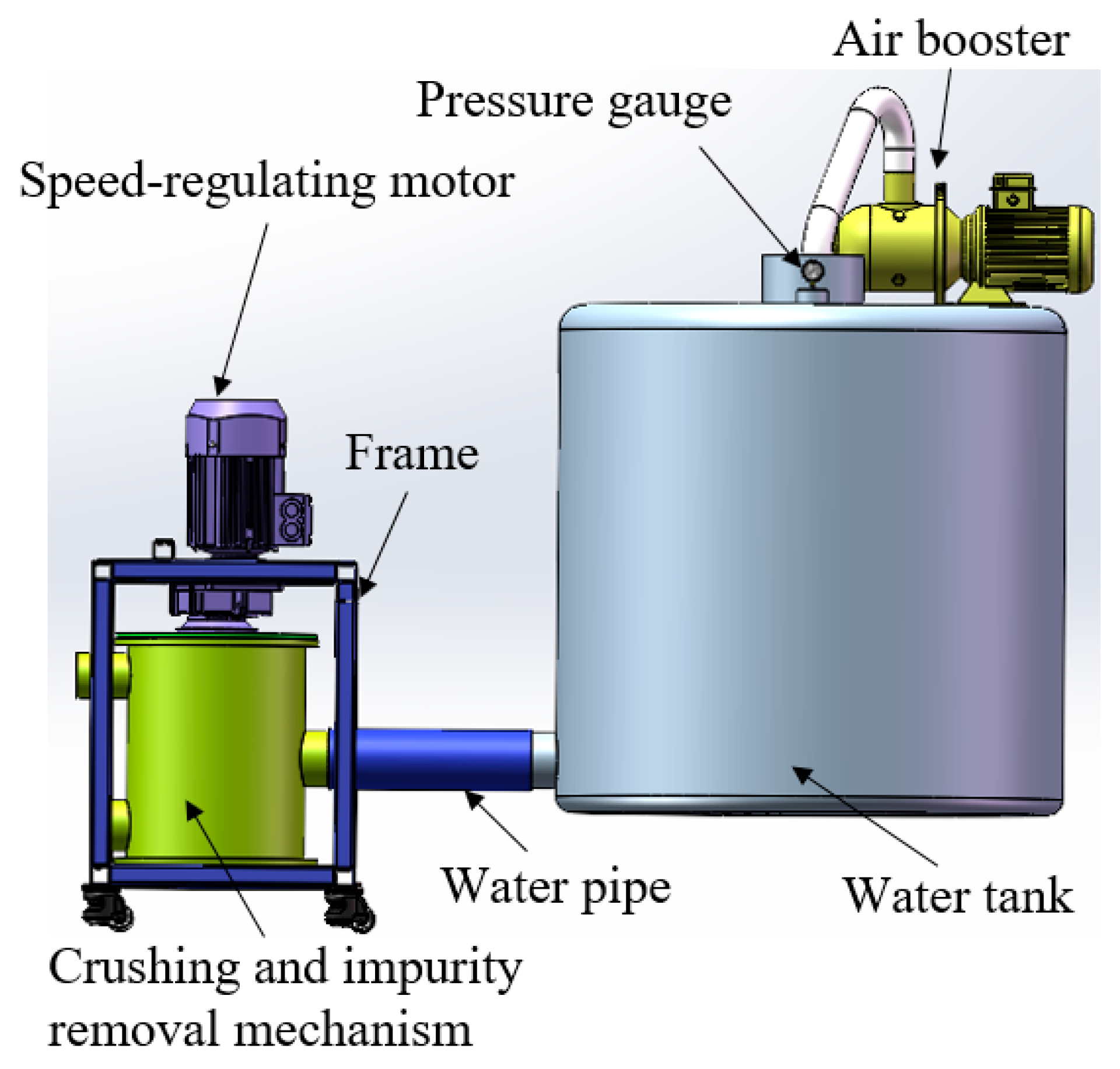
2.1. Structure Design and Working Principles

In the process of crushing and removing impurities, slight blade wear, low energy consumption, and suitable crushing effect of flexible impurities are required. Hence, it is necessary to design crushing and impurity removal devices with adjustable rotation speed and adjustable clearance between the blade and the cutter head in order to meet the requirement of adjusting the key parameters. In this regard, the proposed device is composed of a speed regulating motor, a transmission shaft, a shell, a cross tool holder, a cutter, a cutter head, a multilayer wave spring, and a funnel, as shown in Figure 1. The main function of the device is to feed the liquid manure flowing out of the tank to the distributor after treatment, and thus provide good conditions for multi-channel distribution and smooth application of the liquid manure. In the working process, the motor drives the transmission shaft to rotate, and the transmission shaft thus drives the cross rotary cutter to rotate. The liquid manure enters the crushing and impurity removal chamber from the entrance. The large density impurities such as sand and stones enter the impurity storage chamber through the funnel and are thrown against the inner wall of the shell under the action of the centrifuge. This will prevent impurities from flowing out of the impurity storage chamber. The flexible organic impurities such as hair and straw are chopped by the rotary cutter group under the buoyancy and fluid effects and then flow out of the crushing and impurity removal device through the outlet into the multi-channel distribution device.
During the test, the speed of the cutter shaft can be adjusted by modifying the motor speed and regulating the frequency of the converter. This will result in different cutting speeds [15]. The clearance between the blade and the cutter head can be varied by adjusting the bolt. In addition, different cutter types and cutter head shapes can be obtained by changing blades and cutter discs [16]. Moreover, the influence of different cavity shapes on the fluid can be analyzed by changing the shell.

2.2. Key Components Design and Parameter Determination

2.2.1. Electric Motor Selection

The electric motor is the power source of the whole device. It should not only be equipped with the regulation function of different speeds but also possess a high torque to overcome the liquid resistance and friction between the blade and the cutter head. In addition, it needs to provide enough shear force to cut straw and other impurities. The torque can be selected according to the required shear force of straw. Liquid manure contains a variety of straw, most of which decompose into flocculent matter after fermentation. The decomposition degree of rice straw is relatively low, and the relative size deviation is small, which is conducive to reducing the experimental error, so it is a suitable experimental raw material. The experimental instrument was a WDW model electronic universal testing machine produced by Jinan Chuanbai Instrument Equipment Co., Ltd. (Jinan, China), as shown in Figure 2. Through the shear force test analysis of rice straw of Nanjing 9108 at different cutting speeds, the parameters were obtained as follows.
It can be seen from Table 1 that the shear force decreases with the increase in the cutting speed. In actual applications, the cutting speed is not less than 260 mm/min, and the straw is basically in the sliding-cut state. The sliding-cut shear force is less than the secant shear force. Considering that the motor should in theory be able to adapt to the maximum torque, if the straw is set to the secant-cut state and the shear speed is v = 260 mm/min, then the shear force required to cut off a straw is F = 39.2 N. Since the maximum shearing force arm of straw is the radius of the cutter head L = 0.16 m, the maximum torque required for shearing a straw T1 = 6.272 N·m. Considering that there are not many straw impurities in the real case, it is assumed that each blade cuts two straws simultaneously. Thus, the four blades cut a total of eight straws, and a torque of T2 = 8T1 = 50.176 N·m is required. Hence, the motor torque should be maintained at greater than 51 N·m to ensure normal working conditions. In this work, an F37 parallel-shaft helical gear reduction motor of 2.2 KW was selected. It has a maximum speed of 374 r/min, an output torque of 56 N·m, a reduction gear ratio of 3.77, and a radial load of 2400 N. In order to achieve the purpose of speed adjustment, a frequency converter was externally connected to the motor. Thus, the purpose of obtaining variable speeds could thus be achieved by changing the frequency. The frequency selection of the frequency converter is determined according to the required output speed, according to the following formula:
f = n P 60 1 s
where f is the frequency of frequency converter in Hz; n is the rotating speed of the motor in r·min−1; p = 2 is the number of pole pairs, and s = 0.04 is the slip ratio.

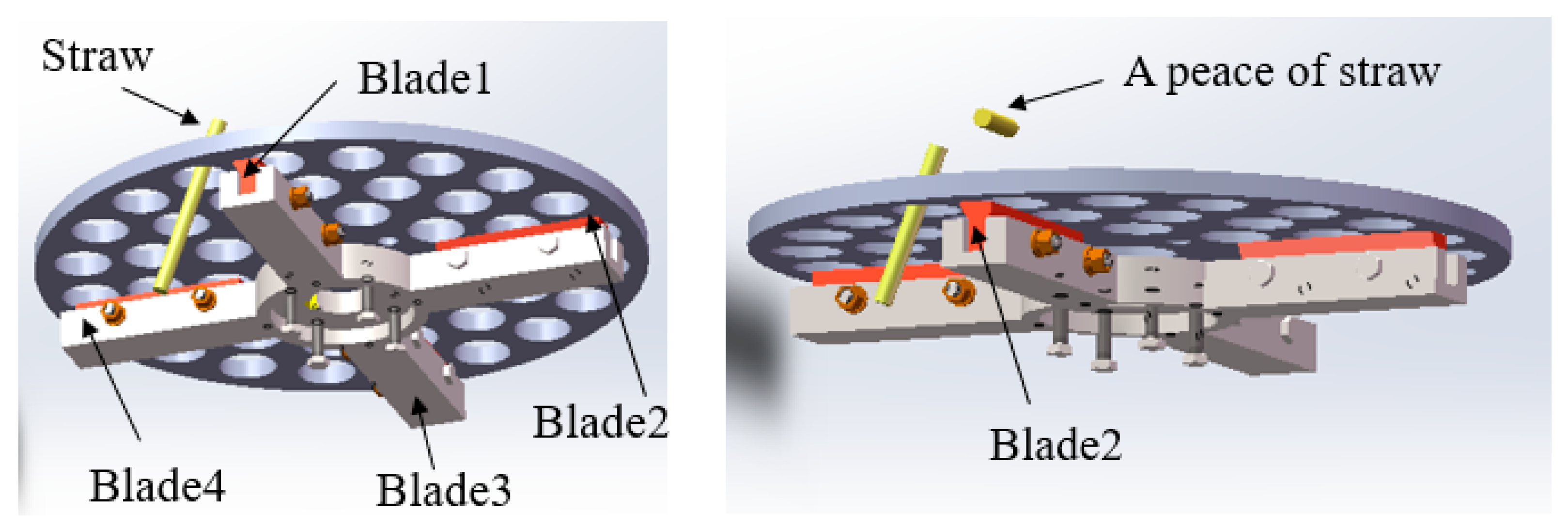
2.2.2. Design of Cross Rotary Cutter Group

The cross rotary cutting tool group is composed of a cutter head, a cross cutter shank, a rotary cutting blade, and a rotating shaft, as shown in Figure 3. Having too many blades will affect the flow rate of liquid manure. On the other hand, if the number of blades is too small, a higher speed is required to ensure the good crushing effect of impurities, which would not only affect the overall flow rate but also increase energy consumption. After overall consideration, the number of blades was set to four. Since the cutter would wear during the working process, the four rotary cutting blades were evenly arranged on the cross tool holder with an angle interval of 90° between adjacent blades in order to save costs and facilitate replacement. When the device is in operation, the transmission shaft drives the tool holder to rotate relative to the cutter head, and the straw and other impurities are cut off when they pass through the holes of the cutter head with the liquid flow. The blade material was Cr12MoV, which is resistant to corrosion and wear [17]. Because the blade angle may have a certain influence on the cutting effect and energy consumption, the blades were made into different shapes with different blade angles for experimental analysis.

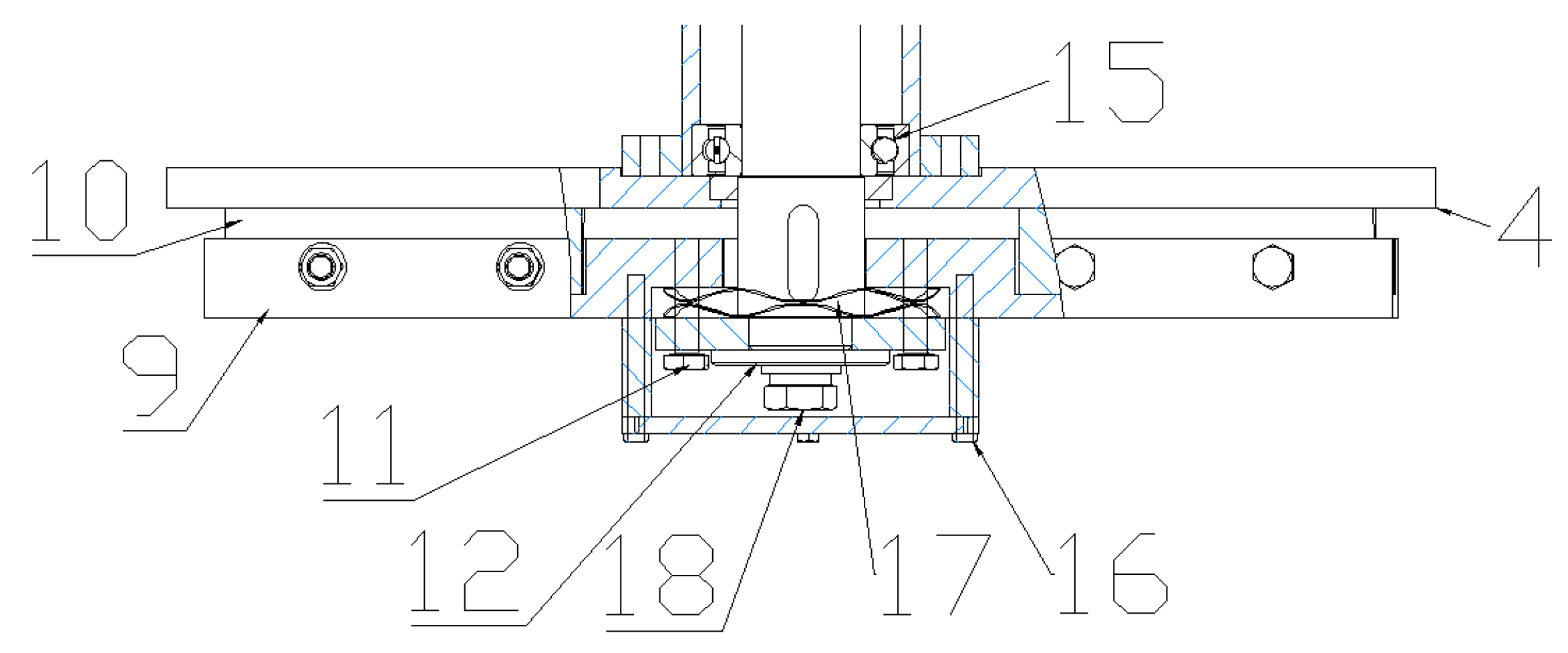
2.2.3. Design of the Wave Spring Cutter-Jacking Mechanism

There are two forms of shear, i.e., clearance shear and non-clearance shear. For the clearance shear, the cutter and cutter disc are not in contact, which can reduce energy consumption and blade wear. For the non-clearance shear, the cutter makes contact with the cutter disc, and there would be inevitable friction during work. This will not only produce energy loss but also lead to the wear of the blades. The greater the contact force, the greater the energy consumption [18,19] When the compression amount of the compressed spring is large, the energy consumption generated by friction would be at its maximum. The maximum energy consumption can be calculated using the following equations:
    F = k Δ X f = μ F W = f s s = 2 π r
where F is the normal stress between blade and cutter head; K = 8.43 is the elastic coefficient of the wave spring; μ is the frictional coefficient between blade and cutter head with a value of 0.15; ΔX is the deformation of the wave spring assumed to be 8 mm; f is the frictional force; s denotes the circumference of a rotation at the center of the cutter; and r = 160 mm is the distance between the midpoint of cutter and the center of circle.
Through calculations, it is shown that the energy consumption generated in one rotation of friction between the cutter and the cutter head is W = 0.52 J. In order to reduce energy consumption, the clearance cutting method was adopted in the case of a slight difference in straw shredding effect, which could avoid the friction loss between the cutter and the cutter head. However, clearance cutting may be less effective than contact cutting. A single-factor comparative test was planned to investigate the effects of different clearances between the cutter and the cutter head on the cutting effect. Thus, a wave spring jacking mechanism was designed, and a bolt adjusting mechanism was set to adjust the clearance between the blade and the cutter head [20].

2.2.4. Determination of the Rotation Speed of the Cross Tool Holder

According to the actual requirements, the designed working efficiency of the device is V = 45 m3/h, and the outlet diameter is R1 = 0.1 m. Thus, it can be deduced that the flow rates at the outlet and at the cutter head are v1 = V/(πr2) and v2 = v1(r12/r22), respectively. Since the diameter of the designed branch pipe is 30 mm, the length of impurities after cutting shall not be higher than 30 mm. Assuming that the speed of straws passing through the holes of the cutter head is 0.33 m/s, 0.079 s is needed for 30 mm and the cutting period of two adjacent cutters is 0.079 s. Thus, it can be deduced that the minimum rotation speed of the cutter head is 190 r/min [21]. The cutting process is shown in Figure 4.

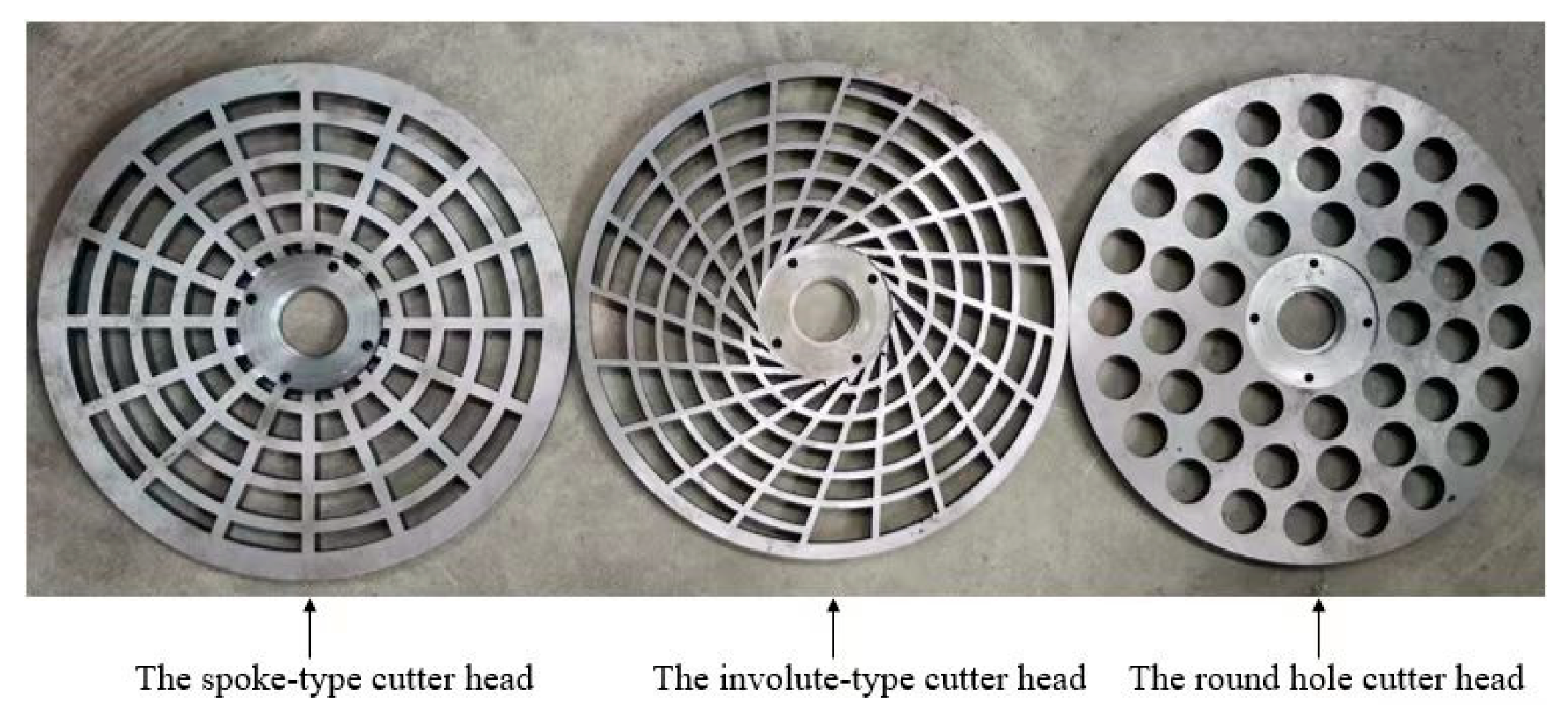
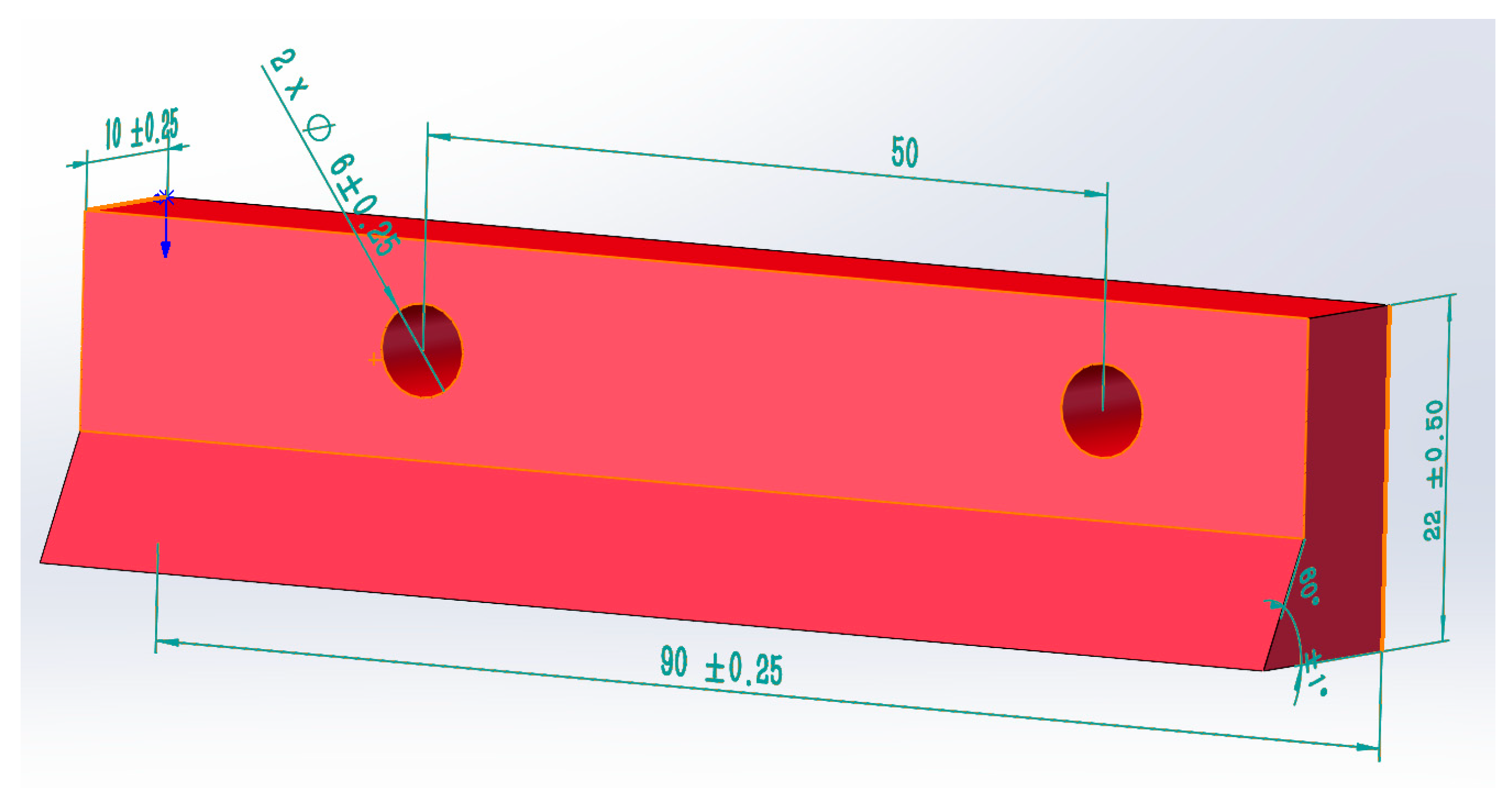
2.2.5. Structure Design of the Cutter Head

The cutter head is one of the key components of the whole mechanism. Different cutter shapes can affect the sliding cutting angle of straw stalk cutting and thus have a certain influence on the crushing effect. In this work, three cutter head shapes were designed, i.e., an involute-type cutter head, a spoke-type cutter head, and a circular hole cutter head, as shown in Figure 5. The cutter head material was alloy steel, and the surface was plated with a TiN coating to increase hardness and wear resistance. In order to compare the cutting effect and energy consumption, a single-factor test was carried out.

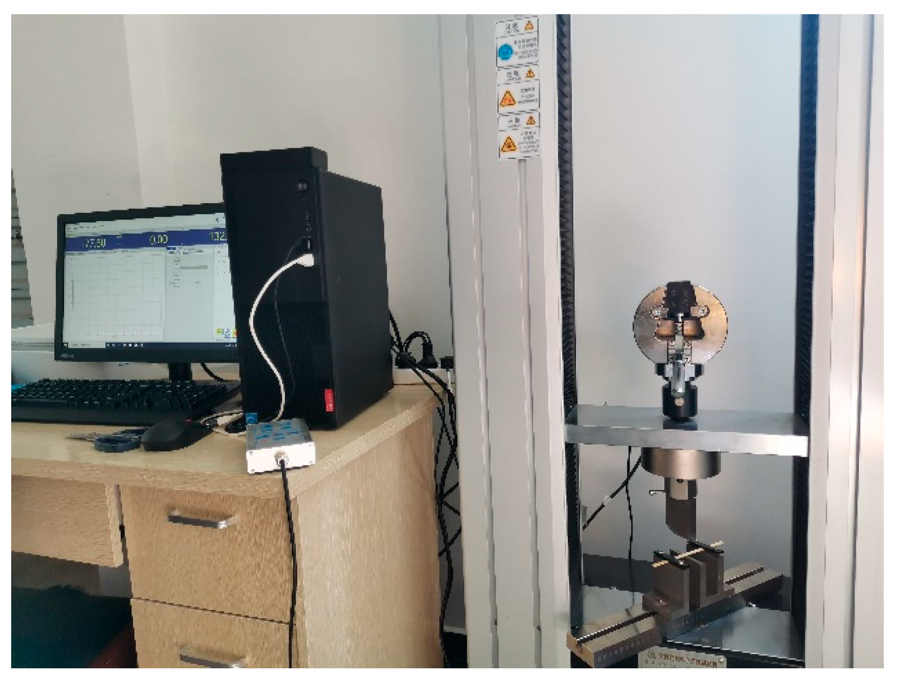
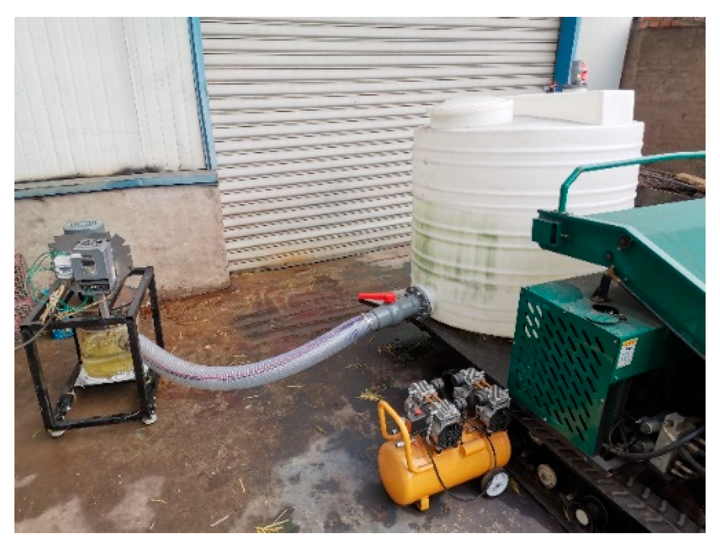
2.3. Test Platform and Testing Principles

To facilitate the setting and adjustment of parameters, a test platform was designed, which consisted of a water tank, an air booster, a pressure gauge, a frame, a speed-regulating motor, a crushing and impurity removal mechanism, and a water pipe, as shown in Figure 6. When the device operates, the water valve is closed and the inlet valve is opened. Then, the air booster starts to increase the pressure in the water tank to the preset pressure. This is followed by turning on the electric motor, where its speed is regulated to the preset rotation speed. Then, the water valve is opened. At the end of the test, the motor and the water valves are closed to complete the work [22].

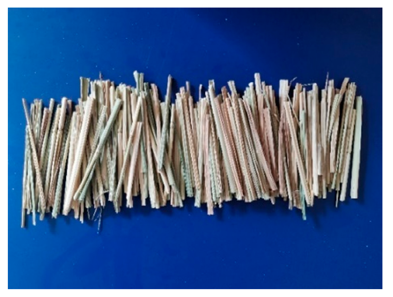
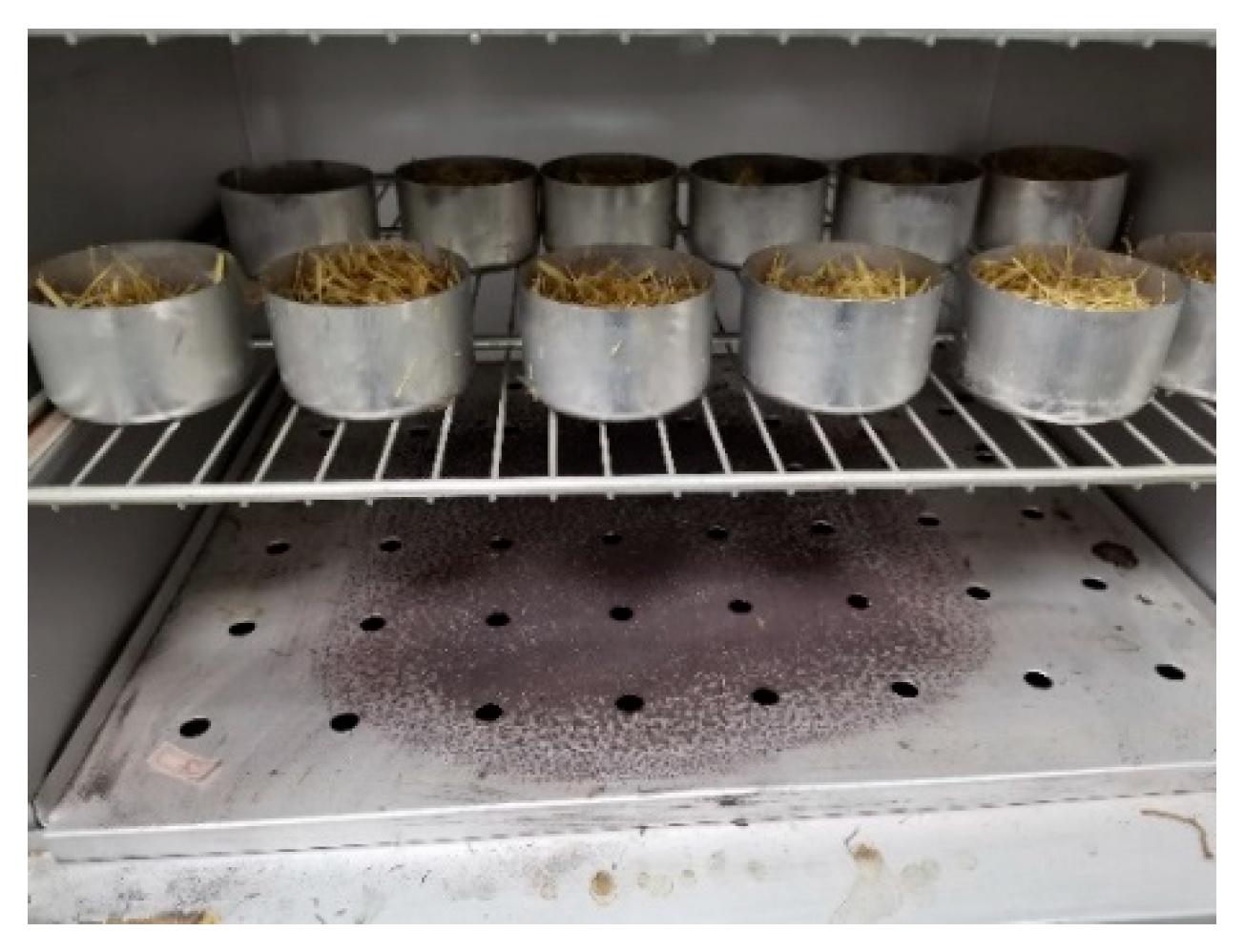
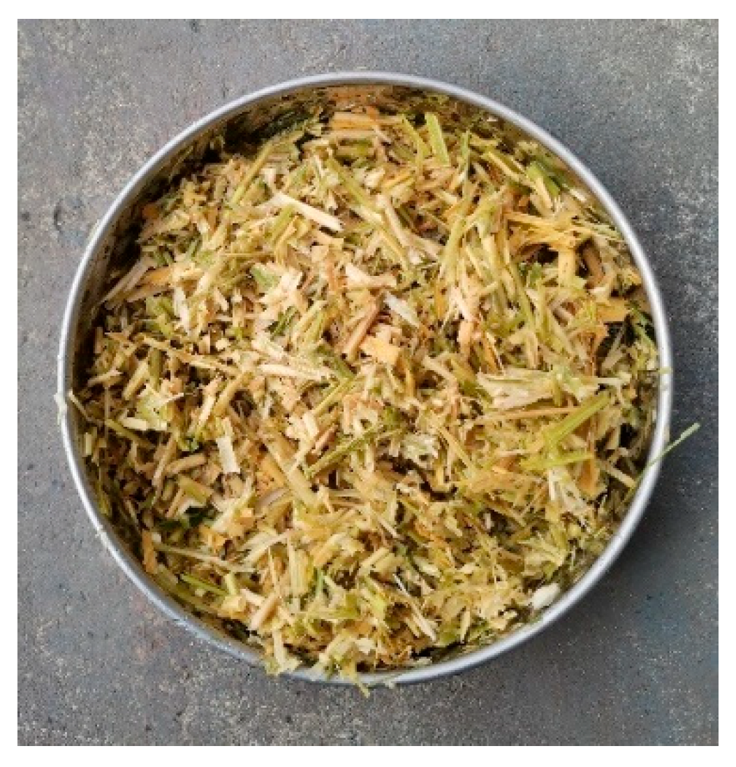
2.4. Experimental Materials

This experiment mainly studied the crushing characteristics of the device. The rice straw harvested from the Nanjing9108 variety in Jiulong Town, Taizhou City, Jiangsu Province was selected as the experimental straw. The experiment was conducted in November 2021. The middle part of the straws was selected for isometric cutting, and the length of each straw section was 100 mm, as shown in Figure 7. The cut straw sections were soaked in water for 48 h to achieve full absorption of water. In the experiment, 100 straw sections were considered in the test at a time. After each test, all straws were collected and dried, as shown in Figure 8, and then the straws with a length greater than 30 mm were weighed to calculate the qualification rate of straw crushing. The qualification rate of straw crushing is calculated using the equation below:
R = G G 1 G × 100 %
where R is the qualification rate of straw crushing; G is the total weight of the 100 straw sections with a length of 100 mm; and G1 is the weight of the straws with a length greater than 30 mm after crushing.
According to the preliminary study on the crushing and impurity removal device for liquid manure, the factors affecting the crushing effect and energy consumption include the shape of the cutter head, the end angle of the cutting blade, the rotation speed of the cutter shaft, and the cutting clearance.
To investigate the influence rules of various factors on the straw cutting effect and energy consumption, four factors affecting the evaluation indexes were considered for experimental research. Each group of experiments was repeated three times to reduce the influence of external factors and the corresponding uncertainties. Combined with the single-factor test results after analysis and processing as well as the influence rules of the factors on the evaluation indexes, the neighboring domain near the optimal solution of a single-factor was taken as the value range of multi-factor test factors. The Box–Behnken central composite design method was used to carry out the multi-factor test on each factor that has an effect on the straw crushing effect. The single-factor test determined the value range and level division manner of the multi-factor test, which provided necessary theoretical support and a reference for the multi-factor test.

3. Results and Discussion

3.1. Single-Factor Experiment

According to the literature review, along with the design considerations and the corresponding analysis, the median values of each factor were set as follows: a tool shaft speed of 280 r/min, a cutting clearance of 2 mm, and a blade edge angle of 60°. Three cutting screen shapes for the cutter head, i.e., circular hole cutter head, spoke-type cutter head, and involute-type cutter head, were designed for the experiment.

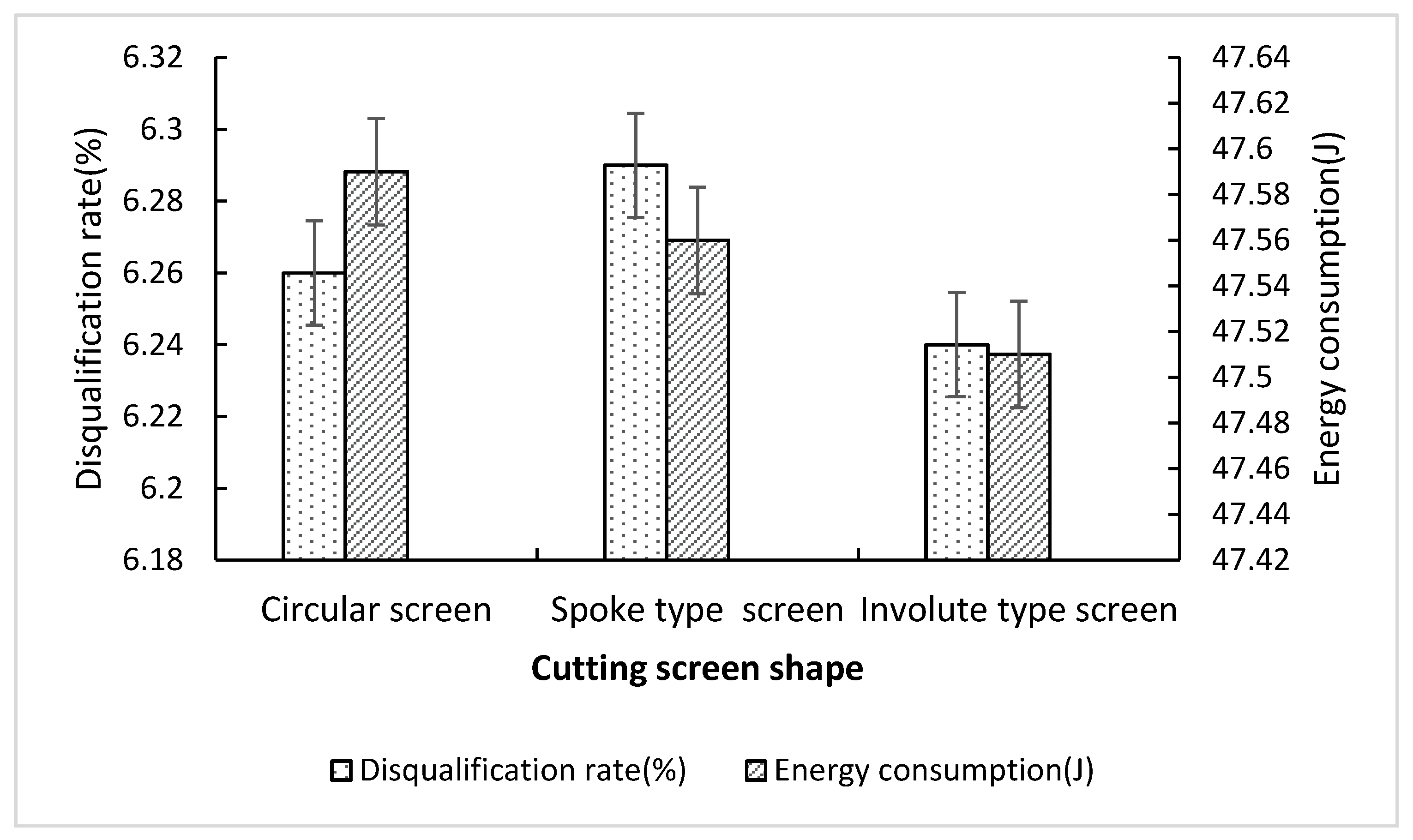
3.1.1. Influences the Cutter Head Cutting Screen Shape on the Straw Crushing Qualification Rate and Energy Consumption

Figure 9 shows the experimental results of the influence of the cutter head cutting screen shape on the qualification rate and energy consumption of the straw crushing. Analyzing the figure results, the energy consumption is at its maximum in the case of the circular hole cutter head, followed by the spoke-type cutter head, and finally the involute-type cutter head, which has the lowest energy consumption. In addition, the disqualification rate is at its maximum in the case of the spoke-type cutter head, followed by the round hole cutter head, and finally the involute-type cutter head. Obviously, the involute-type cutter head has the lowest energy consumption and disqualification rate of straw crushing, indicating that it possesses the best performance of the three cutter heads. Thus, the involute-type cutter head was selected as a base case for the following multi-factor test.

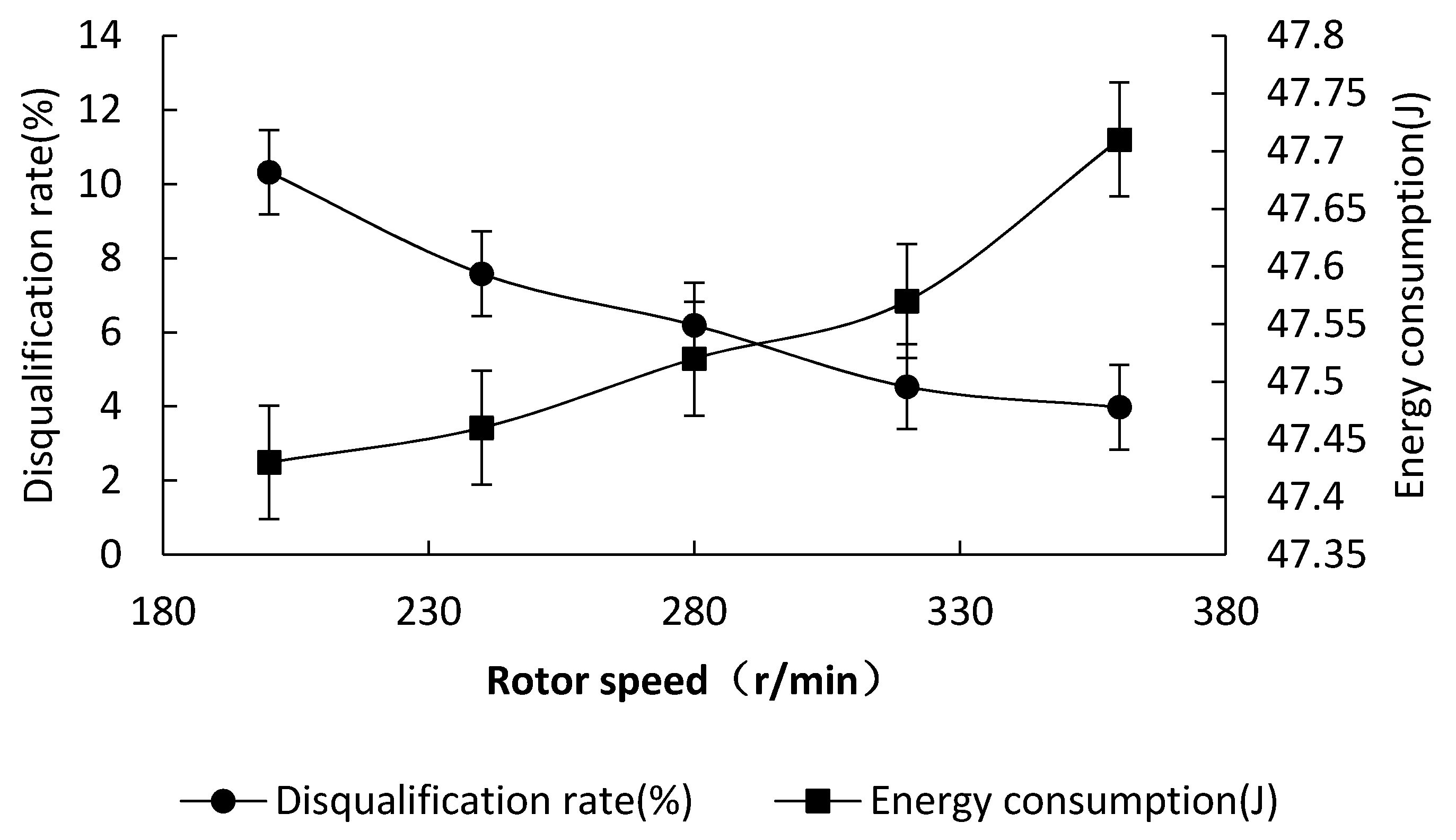
3.1.2. Influences of the Cutter Shaft Rotor Speed on the Qualification Rate and Energy Consumption of Straw Crushing

Figure 10 shows the experimental results of the influence of the rotor speed of the cutter shaft on the qualification rate and energy consumption of the straw crushing. As can be seen from the figure, with the increase in the cutter head rotor speed, the cutting frequency increases, and the instantaneous cutting impulse also increases. As a result, the disqualification rate decreases and the energy consumption increases. When the rotation speed increases from 200 to 240 r/min, the disqualification rate decreases greatly. Moreover, when the rotation speed increases from 320 to 360 r/min, the disqualification rate decreases slightly while the energy consumption increases greatly. Therefore, the cutter shaft speeds of 240, 280, and 320 r/min were selected for subsequent tests.

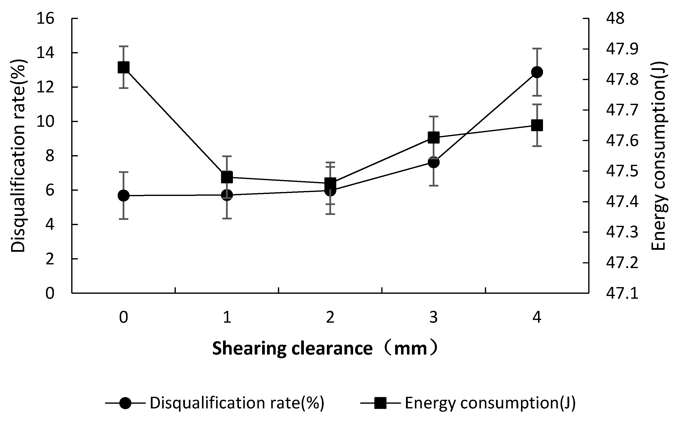
3.1.3. Influences of the Cutting Clearance on the Qualification Rate and Energy Consumption of Straw Crushing

Figure 11 shows the experimental results of the influence of the cutting clearance on the qualification rate and energy consumption of straw crushing. The reported results highlight that with the increase in the cutting clearance from 0 to 2 mm, the disqualification rate increases slightly. In addition, with a further increase in the cutting clearance to 3 mm, it was noted that a small part of straw is not directly cut off and taken away through the clearance or is broken in the clearance. So, the quality of the cutting effect decreases, and the disqualification rate increases rapidly. When the cutting clearance increases from 3 to 4 mm, more straws enter the clearance, resulting in a significant increase in the disqualification rate. In terms of energy consumption, when the cutting clearance is increased from 0 to 1 mm, the energy consumption is greatly reduced due to the low friction between the cutter and the cutter head. In addition, when the cutting clearance increases from 1 to 2 mm, the energy consumption also exhibits a decreasing trend due to the reduction in the frictional force and the corresponding cutting resistance. Moreover, as the cutting clearance is increased from 2 to 4 mm, the energy consumption increases greatly because some straws are squeezed between the cutter and the cutter head. In summary, the cutting clearance was selected as 1 mm, 2 mm, and 3 mm for subsequent tests.

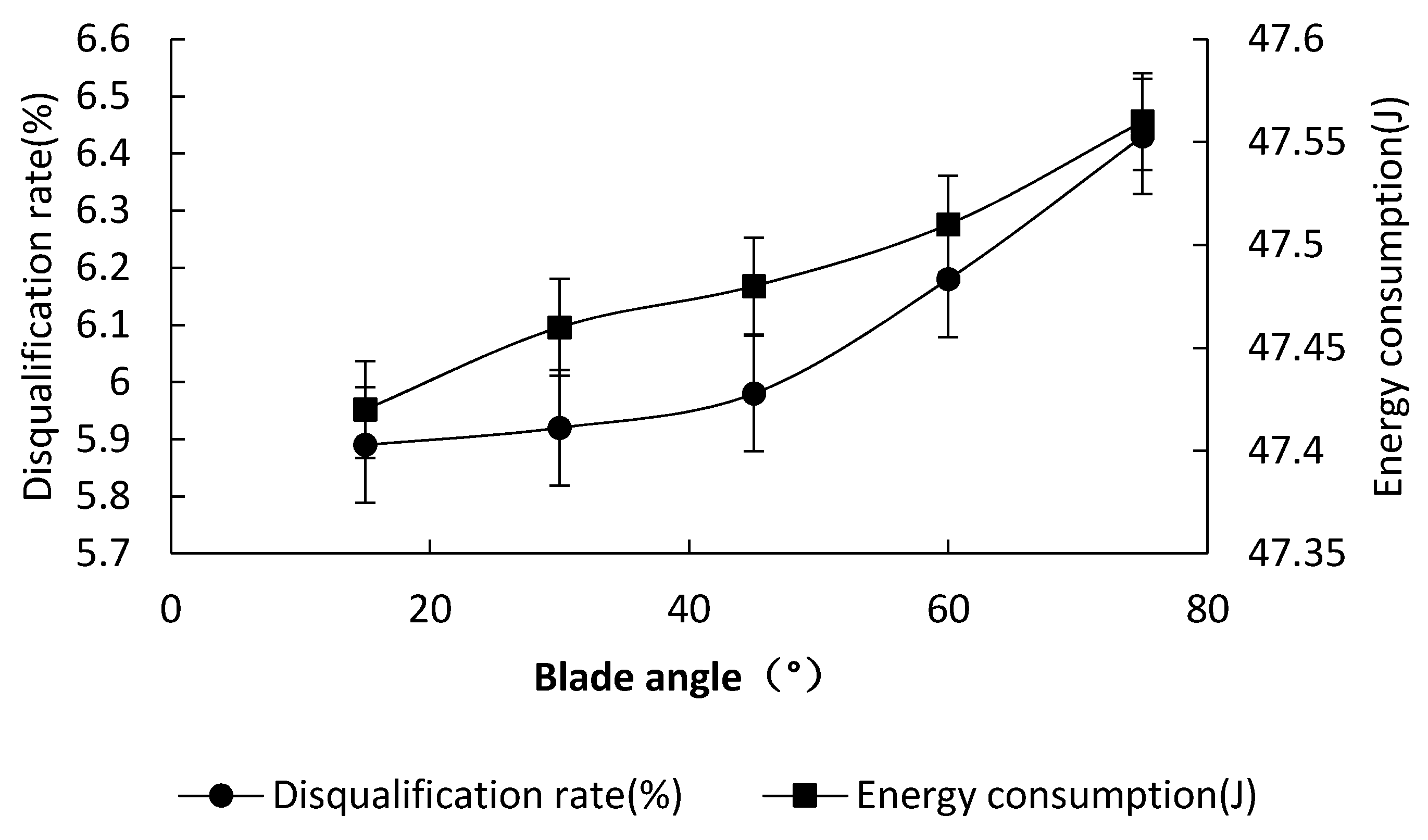
3.1.4. Influences of the Cutter Edge Angle on the Qualification Rate and Energy Consumption of Straw Crushing

Figure 12 shows the experimental results of the influence of the cutter edge angle on the qualification rate and energy consumption of straw crushing. As shown in the results, when the cutter edge angle increases from 15° to 75°, the disqualification rate and energy consumption of straw crushing approximately follow a linearly increasing trend. According to previous studies and literature review, cutters with cutter edge angles of 15° and 30° yield adequate cutting effects but are easily damaged. Hence, cutting edge angles of 45°, 60°, and 75° were selected for subsequent tests, the structural parameters of the blade are shown in Figure 13.

3.2. Response Surface Test

Three-factor and three-level experiments were carried out to investigate the operational performance of the crushing and impurity removal device for liquid manure by using the Box–Behnken central composite design method in Design-Expert8.0.6 software 18. According to the analysis results of the single-factor test, the disqualification rate and working energy consumption of straw crushing were considered as the response values. Considering that, three-factor and three-level experimental evaluations were conducted on the cutter shaft speed, cutting clearance, and cutter edge angle. The codes for the different test factors are shown in Table 2.
The response surface test scheme included 17 test points, i.e., 12 analysis factors and 5 zero estimation errors. The designed scheme and experimental results are shown in Table 3. In the table, A, B, and C are the coded values for the cutter shaft speed, cutting clearance, and cutter edge angle, respectively.

3.2.1. Response Surface Model and Significance Test

The Design-Expert 8.0.6 software was used to conduct a multiple regression fitting analysis employing the data presented in Table 3, and the results are shown in Table 4. Voxler4 was used to draw the relationship graphs between the investigated factors and experimental factors, and the results are presented in Figure 14. Table 4 provides the estimations for the variance analysis employing the regression model. As highlighted by the results, p < 0.001 for the response surface models of the disqualification rate of straw crushing Y1 and the working energy consumption Y2 indicates that the two regression models are highly significant. In addition, the non-fitting items are not significant for the Y1 and Y2 models (p > 0.05), indicating that the regression models have a good fit with the actual situation within the experimental range. The R2 values (determination coefficients) of the Y1 and Y2 models are 99.23% and 98.71%, respectively. The predicted values and the actual values are highly correlated, and the experimental errors are insignificant. Therefore, the model can be used to analyze and predict the indexes of the crushing and impurity removal device for liquid manure with an acceptable satisfaction and accuracy rate.
As can be seen from Table 3, the six regression items of A, B, C, AB, BC, and B2 of the Y1 model are extremely significant (p < 0.01), where AC is significant (p < 0.05) and the other regression items have no significance. In addition, the six regression items of A, B, C, AB, BC, and B2 of the Y2 model are extremely significant (p < 0.01), while the other regression items have no significance (p > 0.05). By retaining the significant items and excluding the non-significant items of the above models, the quadratic polynomial regression models of the disqualification rate Y1 and energy consumption Y2 for the three independent variables (A, B, and C) can be established. Variance analysis was conducted on the established two regression model equations, and the two models were further fitted. In order to ensure that the models are highly significant and the non-fitting items are not significant, the regression models can be optimized as shown in the following equations.
Y 1 = 6.13 1.33 A + 0.76 B + 0.13 C + 0.4 A B + 0.023 A C + 0.03 B C + 0.47 B 2
Y 2 = 47.51 + 0.07 A + 0.04 B + 0.037 C 0.023 A B 0.018 B C + 0.049 B 2

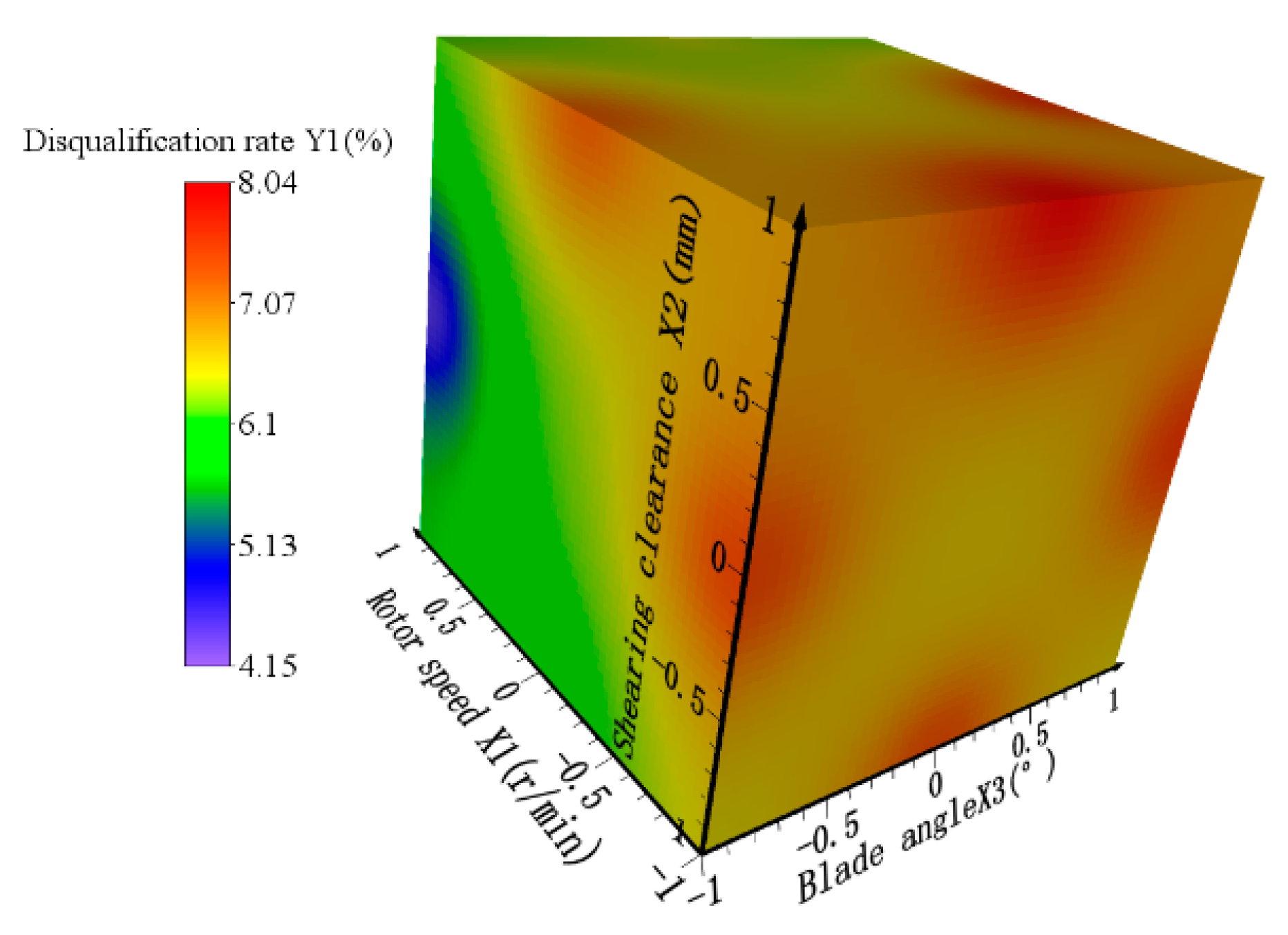
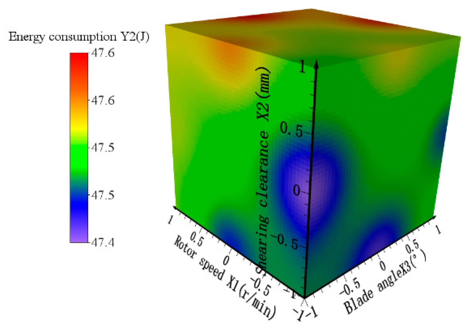
3.2.2. Factor Response Analysis

Considering the values of F presented in Table 4, it can be noted that the sequence of significance degree of the three factors of the cutter shaft speed A, cutting clearance B, and cutter edge angle C for the disqualification rate Y1 follows the following order: A > B > C. Figure 14 shows the influence of A, B, and C on Y1. The following relationships can be identified:
  • The higher the cutter shaft speed, the lower the disqualification rate of straw crushing.
  • The lower the cutting clearance, the lower the disqualification rate of straw crushing
  • The lower the cutter edge angle, the lower the disqualification rate of straw crushing.
These results are consistent with the single-factor test analysis results.
The significance degree of the three factors of cutter shaft speed A, cutting clearance B, and cutter edge angle C in terms of energy consumption Y2 is as follows: A > B > C. Figure 15 shows the influences of A, B, and C on Y2. The following relationships can be identified:
  • The higher the cutter shaft speed, the higher the energy consumption of straw crushing
  • The higher the cutter edge angle, the higher the energy consumption of straw crushing.
These results are consistent with the single-factor test analysis results.

3.2.3. Model Optimization

In order to achieve an ideal operation effect, the disqualification rate of the straw crushing should be as low as possible, as should the working energy consumption. Through the analysis of the effects of various factors, it can be noted that the cutter shaft speed is as high as possible, and the cutting clearance and the cutter edge angle should be as low as possible in order to achieve a low disqualification rate. On the other hand, in order to achieve low working energy consumption, the cutter shaft speed should be as low as possible and the cutter edge angle should be as low as possible. If the straw length after crushing is too long, it would lead to the blocking of the fertilizer hose in the following fertilization process, which would seriously affect the working quality. On the other hand, high energy consumption would increase the operational cost. Considering the real application, constraint conditions were set in the objective optimization calculation. In addition, the weights of the two test indexes were assigned, of which the disqualification rate of straw crushing accounted for 60% and the energy consumption accounted for 40%. Finally, the optimization values of the objective function were obtained. The optimization module of the Design-Expert 8.0.6 software was used to conduct multi-objective optimization design for the regression models of the test indexes. The optimization results of the levels of the three factors by the software analysis highlighted that when the cutter shaft speed was 312.65 r/min, the cutting clearance was 1.36, and the cutter edge angle was 45°, the regression model surface response values were the lowest. In this instance, the disqualification rate predicted by the model was 4.15%, and the energy consumption was 47.53 J.

3.3. Model Verification

Considering the actual working status of the equipment, the optimized parameters were rounded to adjust the tool shaft speed to 312 r/min, the cutting clearance to 1.4 mm, and the cutter edge angle to 45°. In order to verify the reliability of the model prediction results, the optimized parameters were used to conduct six verification tests in Taizhou XieChuang Agricultural Equipment Co., Ltd. (Taizhou, China) in late December of 2021, using the designed and machined test platform, as shown in Figure 16. Then, the test results were averaged. During the tests, the equipment ran smoothly, the equipment vibration was small, and the straw crushing effect was desirable, as shown in Figure 17. The test results are shown in Table 5. The relative errors between the experimental test results of the crushing and impurity removal for liquid manure and the predicted results by the regression model were found to be always less than 5%. Thus, the test results are close to the predicted values by the proposed model, indicating that the parameter optimization regression model has high reliability and acceptable accuracy [23].

4. Conclusions

Addressing the problems of easy blockage and high energy consumption of liquid manure fertilization systems, a crushing and impurity removal device was designed and developed in this work. A test platform was set up, and a single-factor experimental study was conducted. The influences of each of the considered factors on the qualification rate and energy consumption of straw crushing were obtained, and the optimal values of the factors were determined.
Multi-factor response surface tests were carried out with the cutter shaft speed, cutting clearance, and cutter edge angle as test factors. The order of importance of each factor for the unqualified rate of straw crushing is as follows: cutter shaft speed > shear clearance > cutter edge angle. On the other hand, the order of importance of each factor for the energy consumption is as follows: cutter shaft speed > shear clearance > cutter edge angle.
The response surface method was used to optimize the multi-factor data, and the mathematical model of the relationships between the response values and the test factors was established [24]. The optimal parameter combination was obtained as follows: a cutter shaft speed of 312 r/min, a cutting clearance of 1.4 mm, and a cutter edge angle of 45°. The predicted disqualification rate and energy consumption by the prediction model were 4.15% and 47.53 J, respectively. The verification test results considering the optimized parameter combination showed that the disqualification rate and the energy consumption were 4.08% and 47.56 J, respectively, which met the design requirements.
The mechanism of straw crushing In liquid environment was studied in this paper [25]. The optimized structural and kinematic parameters of the liquid manure crushing and the impurity removal device were also obtained through experimental analysis [26]. The results of this work could provide an important reference for future investigations and studies targeting impurity pre-treatment technologies in the application of liquid manure.

Author Contributions

Conceptualization, Z.H. and B.M.; methodology, B.X. and A.W.; machine design, B.M. and M.C.; validation, M.C., Z.H., and J.F.; formal analysis, J.F. and M.C.; investigation, B.M. and A.W.; data curation, J.F. and B.X.; writing—original draft preparation, B.M.; writing—review and editing, B.M.; supervision, Z.H. and B.X. All authors have read and agreed to the published version of the manuscript.

Funding

This research was supported by the Jiangsu Modern Agricultural Machinery Equipment and Technology Demonstration and Promotion Project (NJ2021-23), the Key Research and Development Plan of Anhui Province (2022i01020011), and the Jiangsu Modern Agricultural Machinery Equipment and Technology Demonstration and Promotion Project (NJ2022-26).

Institutional Review Board Statement

Not applicable.

Informed Consent Statement

Not applicable.

Data Availability Statement

Not applicable.

Conflicts of Interest

The authors declare no conflict of interest.

References

  1. Du, W.Y.; Tang, S.; Wang, H. The status of organic fertilizer industry and organic fertilizer resources in China. Soil Fertil. Sci. China 2020, 3, 210–219. [Google Scholar]
  2. Zhao, R.; Dong, H.; Huang, H.; Liu, Y.; Li, H. Research status of fertilizer utilization of livestock and poultry manure in China. J. Chin. Agric. Mech. 2020, 5, 151–156. [Google Scholar]
  3. Sheng, J.; Xu, Q.; Zhu, P.; Sun, G.; Zhang, L.; Zheng, J. Composition analysis of particles filtered from biogas slurry by sieves with different mesh for sprinkling irrigation. Trans. Chin. Soc. Agric. Eng. 2016, 8, 212–216. [Google Scholar]
  4. Zhang, L.; He, Y.; Yang, H.; Tang, Z.; Zheng, Z.; Meng, X. Analysis of the relationship between the development of liquid fertilization machinery and modern agriculture. J. Chin. Agric. Mech. 2021, 42, 34–40. [Google Scholar]
  5. Duran-Ros, M.; Puig-Bargués, J.; Arbat, G.; Barragán, J.; de Cartagena, F.R. Performance and backwashing efficiency of disc and screen filters in microirrigation systems. Biosyst. Eng. 2009, 103, 35–42. [Google Scholar] [CrossRef]
  6. Cui, R.; Cui, C.; Sheng, X.; Lei, J.; Cheng, Z. Research of lamination head loss for two different types of channel structure. J. Water Resour. Water Eng. 2019, 30, 257–260. [Google Scholar]
  7. Yang, P.L.; Lu, P.; Ren, S.M. Experiment on Performance of Disc Filter Based on Fractal Theory. Trans. Chin. Soc. Agric. Mach. 2019, 50, 218–226. [Google Scholar]
  8. Finzi, A.; Guido, V.; Riva, E.; Ferrari, O.; Quilez, D.; Herrero, E.; Provolo, G. Performance and sizing of filtration equipment to replace mineral fertilizer with digestate in drip and sprinkler fertigation. J. Clean. Prod. 2021, 317, 128431. [Google Scholar] [CrossRef]
  9. Marcato, C.E.; Pinelli, E.; Pouech, P.; Winterton, P.; Guiresse, M. Particle size and metal distributions in anaerobically digested pig slurry. Bioresour. Technol. 2008, 99, 2340–2348. [Google Scholar] [CrossRef]
  10. Du, S.Q.; Han, Q.B.; Li, S.B.; Huang, X.Q.; Shang, S.L.; Sun, X.G. Research Status and Development Trend of Filters in Drip Irrigation System. Water Sav. Irrig. 2020, 3, 57–61. [Google Scholar]
  11. Webb, J.; Pain, B.; Bittman, S.; Morgan, J. The impacts of manure application methods on emissions of ammonia, nitrous oxide and on crop response-A review, Agriculture. Ecosyst. Environ. 2010, 137, 39–46. [Google Scholar] [CrossRef]
  12. Zhao, G.; Yang, Z.; Su, H. Design and research of steering wheel type liquid fertilizer deep applicator. Farm Mach. 2014, 2, 116–118. [Google Scholar]
  13. Yuan, H. Development of Biogas Slurry Residue Injection Machinery and Simulation Research of Key Compoments of Fertilizer. Master’s Thesis, Northeast Agricultural University, Harbin, China, 2015. [Google Scholar]
  14. Liu, H.; Xu, G.; Jia, R.; Li, Y. Operating principle and structural optimization of impulse type anti-blocking distribution device for biogas manure. Trans. Chin. Soc. Agric. Eng. 2015, 22, 32–39. [Google Scholar]
  15. Li, T.H.; Meng, Z.W.; Ding, H.H.; Hou, J.L.; Shi, G.Y.; Zhou, K. Mechanical analysis and parameter optimization of cabbage root cutting operation. Trans. Chin. Soc. Agric. Eng. 2020, 7, 63–72. [Google Scholar]
  16. Jiang, Y.; Liao, Y.; Liao, Q. Design and Experiment on Cylinder-type Chopping Device of Harvester for Fodder Rapeseed in Winter and Spring. Trans. Chin. Soc. Agric. Mach. 2019, 2, 102–111. [Google Scholar]
  17. Xu, S. Friction-Wear Characteristics of Ti Al N Film Prepared on the Surface of TA19 Alloy. Master’s Thesis, Nanjing University of Aeronautics and Astronautics, Nanjing, China, 2019. [Google Scholar]
  18. Wang, J.; Song, W.; Jin, C.; Ding, T.; Wang, M.; Wu, J.; Liu, Z. Structural design and process parameter optimization of heat pump drying system of wheel dehumidification for Pleurotus eryngii. Trans. Chin. Soc. Agric. Eng. 2019, 35, 273–280. [Google Scholar]
  19. Shi, Y.; Wang, X.; Zhang, Y.; Morice, O.O.; Ding, W. Test and analysis on the influence factors of reciprocating cutting force of Artemisia Selengensis harvester. J. Chin. Agric. Mech. 2018, 12, 46–53. [Google Scholar]
  20. Li, J.; Zhao, C.; Xiu, W.; Wang, J. Design and experiments on the distribution system of the self-propelled liquid fertilizer machine. J. Chin. Agric. Mech. 2015, 36, 49–53. [Google Scholar]
  21. Li, H.; Shen, W.Q.; Ban, T. Research progress of the ues of technology and crushing equipment on straw in China. J. Chin. Agric. Mech. 2018, 39, 17–21. [Google Scholar]
  22. Zhang, D.; Sun, W.; Liu, X.; Zhang, H.; Zhang, R.; Zhang, W. Design and research of the combined cutting and kneading silage corn crusher. J. Chin. Agric. Mech. 2019, 40, 93–100. [Google Scholar]
  23. Pedersen, J.M.; Feilberg, A.; Kamp, J.N.; Hafner, S.; Nyord, T. Ammonia emission measurement with an online wind tunnel system for evaluation of manure application techniques. Atmos. Environ. 2020, 230, 117562. [Google Scholar] [CrossRef]
  24. Hansen, M.N. Influence of Storage of Deep Litter Manure on Ammonia Loss and Uniformity of Mass and Nutrient Distribution following Land Spreading. Biosyst. Eng. 2004, 87, 99–107. [Google Scholar] [CrossRef]
  25. Sogaard, H.T.; Sommer, S.G.; Hutchings, N.J.; Huijsmans, J.F.M.; Bussink, D.W.; Nicholson, F. Ammonia volatilization from field-applied animal slurry-the ALFAM model. Atmos. Environ. 2002, 36, 3309–3319. [Google Scholar] [CrossRef]
  26. Rodhe, L.; Etana, A. Performance of Slurry Injectors compared with Band Spreading on Three Swedish Soils with Ley. Biosyst. Eng. 2005, 92, 107–118. [Google Scholar] [CrossRef]
Figure 1. Structure chart of the crushing and impurity removal device. (1) Adjustable-speed motor, (2) transmission shaft, (3) outlet, (4) cutter head, (5) cross rotary cutter group, (6) impurities outlet, (7) funnel, (8) inlet, (9) cross tool holder, (10) blade.
Agriculture 12 01228 g001
Figure 2. Straw shear force test.
Agriculture 12 01228 g002
Figure 3. Cross rotary cutter group. (4) cutter head, (9) cross tool holder, (10) blade, (11) Bolt guide, (12) shaft end washer, (15) bearing, (16) fixed bolt, (17) multilayer wave spring, (18) shaft end bolts.
Agriculture 12 01228 g003
Figure 4. Cutting process of straw.
Agriculture 12 01228 g004
Figure 5. Three designed cutter heads.
Agriculture 12 01228 g005
Figure 6. Schematic of the test platform.
Agriculture 12 01228 g006
Figure 7. Straws for experiment.
Agriculture 12 01228 g007
Figure 8. Straw drying after crushing experiment.
Agriculture 12 01228 g008
Figure 9. Experimental results of the influence of the cutter head cutting screen shape on the qualification rate and energy consumption of straw crushing.
Agriculture 12 01228 g009
Figure 10. Experimental results of the influence of the cutter shaft rotor speed on the qualification rate and energy consumption of straw crushing.
Agriculture 12 01228 g010
Figure 11. Experimental results of the influence of the cutting clearance on the qualification rate and energy consumption of straw crushing.
Agriculture 12 01228 g011
Figure 12. Experimental results of the influence of the cutter edge angle on the qualification rate and energy consumption of straw crushing.
Agriculture 12 01228 g012
Figure 13. Schematic of the blade.
Agriculture 12 01228 g013
Figure 14. Four-dimensional rendering graph illustrating the influence of the cutter shaft speed, cutting clearance, and cutter edge angle on the disqualification rate.
Agriculture 12 01228 g014
Figure 15. Four-dimensional rendering graph illustrating the influence of the cutter shaft speed, cutting clearance, and cutter edge angle on the energy consumption of straw crushing.
Agriculture 12 01228 g015
Figure 16. Digital image of bench test.
Agriculture 12 01228 g016
Figure 17. Straw after crushing.
Agriculture 12 01228 g017
Table 1. Influence of cutting speed on the peak value force.
Cutting speed (mm/min)60110160210260
Secant peak value force (N)56.854.147.243.739.2
Table 2. Test factor codes.
CodeFactors
Rotor Speed (r/min)Shearing Clearance (mm)Blade Angle (°)
−12406045
02807060
13208075
Table 3. Test design scheme and results.
Test FactorsABCDisqualification Rate (%)Energy Consumption (J)
1−1108.0947.56
201−16.4547.59
30−116.0847.58
40006.1647.53
51106.3247.65
60006.1947.52
710−14.3147.55
80006.1947.51
9−1−107.2747.44
10−1018.0147.48
110006.0947.51
120117.7347.63
131015.7147.64
140006.0247.5
151−104.1547.62
160−1−15.5447.47
17−10−17.2447.42
Table 4. Variance and analysis of regression model.
SourceDisqualification RateEnergy Consumption
Sum of SquaresDfF-Valuep-ValueSum of SquaresDfF-Valuep-Value
Model19.669204.74<0.00010.077997.04<0.0001
A12.811200<0.00010.0391442.58<0.0001
B3.851360.93<0.00010.0131144.52<0.0001
C1.991186.54<0.00010.0111127.02<0.0001
AB0.46142.710.00030.002122.860.0020
AC0.119.30.01860.000212.540.1550
BC0.14112.830.00890.0012113.830.0075
A20.0413.750.09390.0000810.860.3849
B20.22120.850.00260.011115.31<0.0001
C20.0313.20.11690.0000810.860.3849
Residual0.07467573.230.14330.0006270.256410.8537
Lack of fit0.05287533.563
Pure error0.021840.774
Cor total19.731591696.5616
Table 5. Bench test results.
TypeDisqualification Rate (%)Energy Consumption (J)
Test value4.1547.53
Predictive value model4.0847.56
Coefficient of variation1.690.06
Publisher’s Note: MDPI stays neutral with regard to jurisdictional claims in published maps and institutional affiliations.

