Article

Design and Experiment of Quantitative Seed Feeding Wheel of Air-Assisted High-Speed Precision Seed Metering Device

1
College of Mechanical and Electronic Engineering, Northwest A & F University, Yangling 712100, China
2
College of Engineering, China Agricultural University, Beijing 100083, China
3
College of Mechanical and Electrical Engineering, Tarim University, Alar 843300, China
*
Author to whom correspondence should be addressed.
These authors contributed equally to this work.
Agriculture 2022, 12(11), 1951; https://doi.org/10.3390/agriculture12111951
Submission received: 6 October 2022 / Revised: 12 November 2022 / Accepted: 12 November 2022 / Published: 19 November 2022
(This article belongs to the Section Agricultural Technology)

Abstract

:
Aiming to solve the problems of the poor uniformity of seed flow discharge and serious damage of traditional straight grooved wheels to improve the performance of air-assisted maize high-speed precision seed metering devices, a staggering symmetrical spiral grooved feeding wheel with maize seeds was designed. To explore the influence of the spiral groove inclination angle and the length of the staggered symmetrical spiral groove feed wheel on the uniformity of seed flow discharge, the spiral groove length l and the spiral groove inclination angle ρ were used as the experimental factors, and the variation coefficient of the increase in seed, a full-factor simulation test was carried out for the test indicators, and it was found that both the inclination angle and the length of the spiral groove have an influence on the uniformity of seed flow discharge, and the influence of the inclination angle of the groove is more significant. Comparing the force of a single seed in the traditional straight grooved wheel and that of the spiral feeding wheel, it is found that the staggered symmetrical spiral grooved feeding wheel can reduce the damage of seed fertilizer. Through a bench test, the spiral groove length was found to be 50 mm, and the groove inclination angles are 30°, 45° and 90°. The test results show the variation trend and simulation results of the fluctuating coefficient of variation of the seed flow discharge in the bench test. The trend of change is basically the same. The inclination angle of the spiral groove is 45° and the uniformity of seed flow discharge is the best when the groove length is 50 mm, indicating that this structure can effectively improve the uniformity of material discharge, and the variation coefficient of seed flow discharge fluctuation is 3.12% and the seed breakage rate is 0.69%. Through the seeding performance test, it is verified that the staggered symmetrical spiral grooved feeding wheel can improve the seeding performance of the pneumatic high-speed precision metering device. When the metering device runs smoothly, the qualified rate reaches more than 90%, and the leakage rate is reduced to 0%. Therefore, the results of this study can provide a reference for research on uniform seeding, drill seeding and the uniform application of granular fertilizer.

Graphical Abstract

1. Introduction

The support of China’s national policies, large-scale land transfer, and the development of agricultural management methods for large-scale and intensive land use makes the need for advanced and efficient agricultural production technology more urgent [1]. High-speed precision sowing technology has gradually become a cornerstone of field agricultural production, and it is also an important way to ensure crop growth and development and a high yield in modern agricultural production [2,3,4,5]. Gao et al. developed a high-speed pneumatic precision centrifugal seed metering device, representing a technological breakthrough, that effectively used the centrifugal effect produced under high-speed operation, generated favorable conditions despite several unfavorable factors being present, overcame the restriction of speed factors, and can complete high-speed precision maize seed metering at above 14 km/s [6]. However, due to the high-speed rotation of the seeding plate, it is necessary to provide it with a continuous and uniform flow of seeds, so there is an urgent need to develop a device with a simple structure suitable for continuous and uniform seed feeding at high speed.
Since the outer groove wheel has the advantage of a simple structure, with a low cost and showing high adaptability to various materials, it is often used in quantitative planting and fertilizer discharging in agricultural production [7,8]. The quantitative seed feeding device of the grooved wheel was used in this study to provide seeds for the high-speed centrifugal precision seed metering device for gas distribution. However, the existing grooved outer wheel structure can easily cause seed damage under high-speed operations, and the pulsation is more obvious at low displacement and low speed, which can cause the intermittent discharge of seed flow and affect the uniformity of discharge [9]. Scholars have conducted a lot of research to improve the discharge uniformity of the seed flow when the outer grooved wheel is operating. Tian et al. designed a spiral groove-type rice direct seeding device and used Matlab to investigate the seed movement trajectory of rice bud seeds in the spiral groove [10]. Liu et al., in order to solve the pulse problem of the outer grooved wheel seed metering device, designed a grooved spiral wheel, and their research was carried out based on the opening and angle of the groove [11]. These results show that the suitable working parameters of the spiral groove structure can reduce the pulsation of the seed metering to some extent. Jiang et al., to assess the influence of the pulse characteristics of the outer grooved wheel seed metering device on the detection accuracy, studied the pulse characteristics of three kinds of structural grooved pulley, and concluded that the pulsation of seed metering can be effectively reduced by changing the structural parameters of the grooved wheel [12]. Yi et al., in order to guarantee the uniformity of seed metering and the accuracy of the seeding rate, improved the structure of the outer grooved wheel seed metering device and verified this through experiments [13]. Karayel et al. analyzed the consistency of seed spacing discharged by the external grooved wheel seed metering device [14]. High-speed precision seed metering requires a continuous and uniform seed flow with high accuracy; therefore, there are higher requirements for the seed feeding device, and the current outer groove wheel structure cannot meet the accuracy and high-speed requirements.
For this purpose, a new staggered and symmetrical spiral grooved seed feeding wheel was designed based on the outer groove wheel structure. The structural parameters were determined by theoretical calculations. Mechanical and kinematic analyses of the seeds in the flutes were carried out to identify the main factors influencing the uniform discharge of the seeds and full-factor tests were carried out to determine the influence and optimal combinations of the parameters. Comparative tests with existing seed feeding wheels showed that the new structure of the seed feeding wheel is suitable for high speed operations and effectively improves the uniformity and continuity of seed discharge, while also reducing seed breakage. This provides a reference for the development of high-speed uniform seed feeding technology and equipment.

2. Materials and Methods

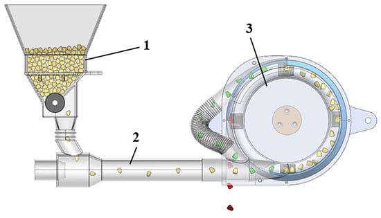
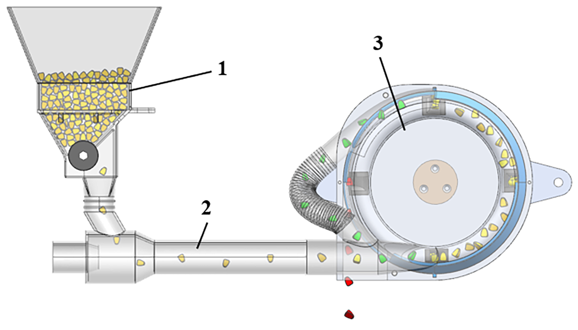
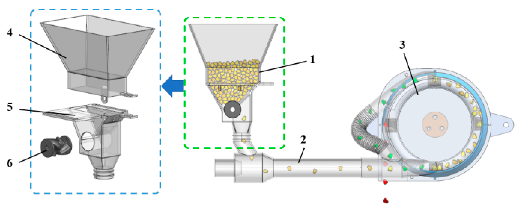
2.1. Structure and Working Principle of the Seed Feeding Device

In the high-speed pneumatic precision centrifugal seed metering system, the main components are a seed feeding device, venturi tube, and seed metering device; the seed feeding device includes a seed inlet, seed filling box and seed feeding wheel, as shown in Figure 1.
Seeds were statically accumulated through the seed feeding device to ensure uniform seed flow through the venturi tube into a high-speed rotating precision rotating seed metering device to complete precision single seed precision sowing [15]. The uniform and continuous flow of seeds is the prerequisite for the high-performance precision seed metering of a high-speed air centrifugal precision seed measuring device, and the seed feeding device is the key to realizing this precondition.
A symmetrical staggered spiral groove-type seed feeding device was designed in this study. The seeds enter from the seed inlet and fall into the filling box, and are filled into the groove of the seed feeding wheel under the gravity and the interaction force between the seeds. When the motor rotates the grooved wheel, the seed is pushed out of the groove driven by the grooved wheel and the seed feeding process is completed.

2.2. Structural Design of Seed Feeding Wheel

The seed wheels with different structures will affect the uniform continuity of the seed flow, which will affect subsequent seed movement. To explore the effects of different structural seed wheels on the characteristics of seed movement, three kinds of structural seed wheels were designed, as shown in Figure 2. Type A is a straight groove-type seed wheel, Type B is a spiral groove-type seed wheel, and Type C is a grid groove-type seed wheel, all of which are made of resin material and processed by 3D printing technology.
The seed feeding device was simulated under three different seed feeding wheels. As can be seen in Figure 2, in the case of the Type A structure, the seeds are uniformly and evenly distributed in the horizontal direction, but discontinuous in the circumferential direction. With the Type B structure, the circumferential direction of the seeds is uninterrupted, but there are more seeds on the right side than on the left side in the grooves, and the distribution is uneven. For the Type C structure, seeds are uninterrupted in the circumferential direction, and seeds are distributed evenly in grooves. To illustrate this further, data from the simulation results were extracted, as well as seed number curves overtime for the Type A, Type B, and Type C structures, as shown in Figure 3.
The above figure shows that the variation range of the number of type A seed measurements is the largest and the momentum fluctuation is the most important in the seed feeding wheel. This is because the Type A structure has a straight groove, and when the seed wheel rotates to the alveolar, a large number of seeds will be discharged, and the number of seeds discharged at the tooth ridge will be greatly reduced. Obviously, the continuity and fluctuation amplitude of the Type B seed wheel are obviously better than those of Type A, but there is still a problem of large pulse fluctuation of impulses. Although this is because the Type B structure is spirally grooved, and the spiral grooves are connected from end to end, avoiding the interruption of seeds, the seeds in the spiral grooving are unevenly distributed under the action of spiral thrust, which causes fluctuations in seed quantity in the process. The fluctuation range of the Type C seed feeding wheel is the smallest among the three types of seed feeding wheels, and the uniform stability is relatively satisfactory. This is because the Type C structure is a grid groove; that is, a grid is added on the basis of a spiral groove, which avoids the uneven distribution of seeds in the slot under the action of spiral thrust, and makes the seed flow relatively uniform and ensures an orderly discharge, but there is a problem with sticking in the grid, which seriously affects the uniformity of the subsequent seed discharge.
We aimed to further improve the uniformity of seed flow discharge and the accuracy of seed provisioning, as well as avoid the occurrence of seed jamming. The above analysis suggests that from the point of view of reducing the pulsation of seed flow discharge and improving the uniformity, a symmetrically staggered spiral grooved seed feeding wheel was optimized and designed.
The spiral groove is staggered symmetrically, and during the seeding process, when the seeds in the groove have finished seeding, they continue to be seeded in a groove on the side. In addition to improving the uniformity of the seed flow, the staggered symmetrical structure can effectively reduce the uneven distribution of seeds under the action of the spiral push in the groove. In the case of a large, unloaded seed, in order to make the seed fall smoothly, there is no sticking and arching phenomenon, and there is some distance between the two symmetric grooves.

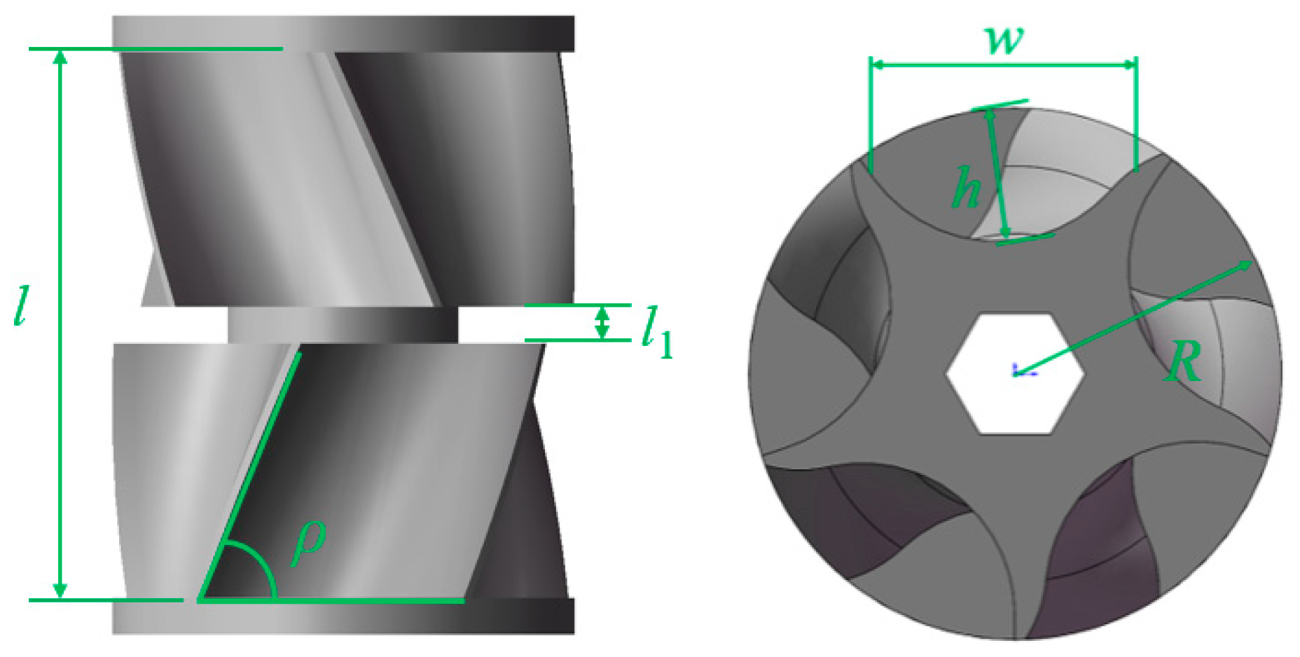
2.2.1. Determination of Structural Parameters of Seed Feeding Wheel

For the seed feed wheel with the staggered symmetric spiral groove type, the structural parameters mainly include the spiral groove length l, groove depth h, groove width w, the distance between two symmetrical spiral grooves l1, the spiral inclination angle ρ and the seed wheel radius R, as shown in Figure 4. The seed feeding rate of the symmetrical staggered spiral grooved seed feeding wheel is as shown in Formula (1) [16]. When the seed feeding rate is constant, the spiral groove length l, the seed wheel radius R and the motor speed n are inversely proportional, and if the length is too long or the radius is too large, the speed will be reduced accordingly, resulting in a uniform decrease in the seed flow rate and increase in the rotational speed. Reductions in the seed feeding wheel radius and length can effectively improve the uniformity of the seed flow discharge of the seed feed wheel, but when the spinning speed is too large, the seed fragmentation rate will increase. Additionally, since the filling of the seed flow is reduced, which affects the stability of the flow discharge of the seeds, it is necessary to choose an appropriate length and radius for the wheel [17,18,19].
{ q = 2 π R l γ ( α 0 f t + λ ) Q = q n
where q is the seed discharge per turn of seed feeding wheel, g/r; γ is the seed density, g/cm3; α0 is the seed filling coefficient in spiral grooves; f is the cross-sectional area of a single groove, mm; t is the spiral groove pitch; λ is the characteristic parameters of the driving layer; R is the rotation radius, mm; Q is the seed feeding rate, g/min; l is the spiral groove length, mm; and n is the motor speed, r/min.
To ensure the applicability of the grooved wheel, a particle with poor flowability and irregular shape and size (e.g., maize seed) was chosen for seeding performance research. Defining relevant design parameters requires a measure of the seed size. Based on shape, maize seeds are roughly divided into four types: large flat, small flat, class large circle, and class small circle. The triaxial dimensions of maize seeds were measured and the average values were calculated. The average length is 11.13 mm, the average width is 8.71 mm, and the average thickness is 5.70 mm [18,20].
For the seeds in the spiral groove to be able to be filled smoothly and avoid leakage, and at the same time to meet the higher precision seed feeding requirements of the seed feeding wheel, the groove depth h of the seed feeding wheel should be greater than the width of 1 maize seed and less than 2 maize seed widths. The width of the spiral groove should be 1–2 times the direction of the length of the maize seed. Because the spiral groove is symmetrical, in order to make it so that the groove can be filled with seeds smoothly, the length of the groove l should be greater than the width of the two maize seeds. With the aim of maize seeds falling softly from grooves and reducing the arching of maize seeds, there is a gap between two symmetrical grooves of the seed feeding wheel. To prevent the leakage of seeds from the gap during work, however, the spacing l1 between symmetrical spiral grooves should be between 0.5 and 1 times the thickness of the seeds. The depth h of the spiral groove, the groove width w, the groove length l and the spacing l1 between the symmetrical spiral grooves should meet the following formula:
{ w 0 ¯ < h < 2 w 0 ¯ l 0 ¯ < w < 2 l 0 ¯ 0 . 5 t 0 ¯ < l 0 < t 0 ¯ l > 2 w 0 ¯
where w 0 ¯ is the average seed width, mm; l 0 ¯ is the average seed length, mm; t 0 ¯ is the average seed thickness mm; h is the spiral groove depth, mm; w is the spiral groove width, mm; and l1 is the symmetrical spiral groove spacing, mm.
The above formula gives the depth h of the spiral groove as 10 mm, the width w of the groove as 16 mm, and the spacing l1 between symmetric spiral grooves as 3 mm. To ensure a good seed filling efficiency and seed fragmentation rate in the spiral groove, the radius R of the seed wheel is 19 mm, and the horizontal range of the spiral groove length l is 20~50 mm. The effect of the spiral groove length on the seed flow discharge uniformity is determined in an experiment described later in the paper.

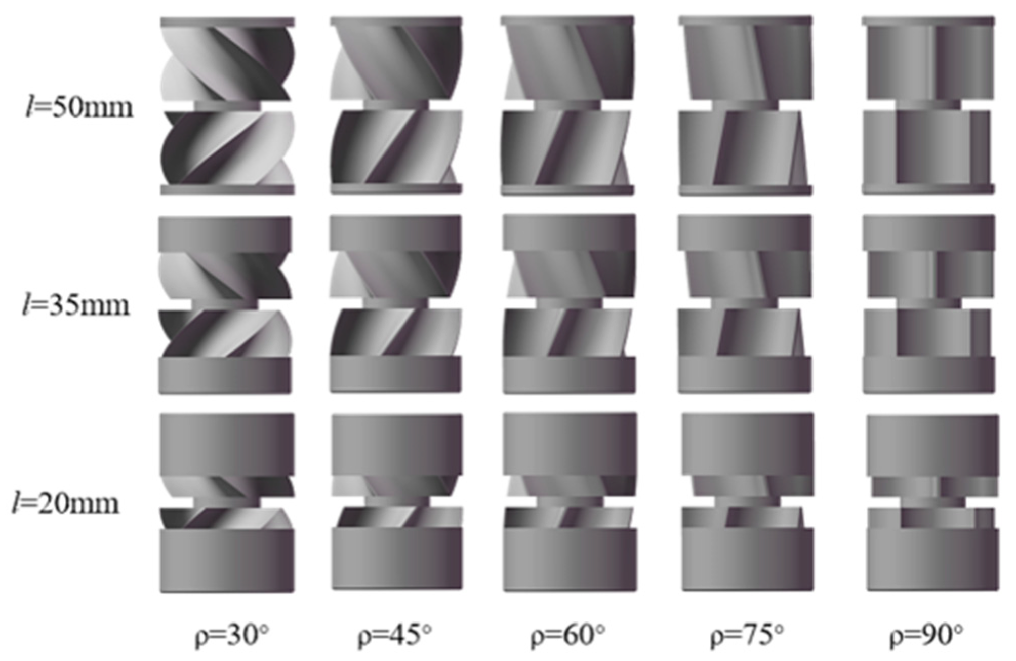
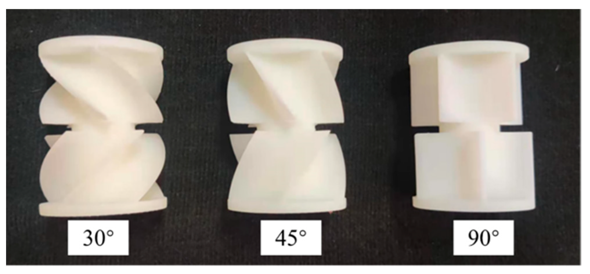
2.2.2. Groove Helical Inclination Range

With the rotation of the seed wheel, seeds spatially move through the spiral grooves. Due to the complexity of the seeds in the spiral grooves, seeds in the spiral grooves were taken as the research object, the single seed was taken as the particle and the relative slip between the seeds was ignored, and its dynamics were analyzed [20,21,22,23,24,25]. The helix was opened and is expressed by an oblique line; the ρ is the inclination angle of the groove. When the angle of inclination is less than the residual angle of friction between the seed and groove, the seed will slip. The force analysis of the expansion plane is shown in Figure 5.
A coordinate system with the x-axis and y-axis of vertical axis was established. The seed moves in space in the grooved wheel, and it is supported by the grooved wheel FN and by the maximum static friction force fN between the grooved wheel and the seed. Since the seed tends to move downward along the helix, the seed friction moves upward along the helix plane. The resultant force on the seed is decomposed into two forces in the x direction and y direction, which are Fx and Fy, respectively, as shown in Formula (3).
{ F x = F N cos ρ f N sin ρ F y = G F N sin ρ f N cos ρ f N = F N tan φ , ( ρ 90 φ )
where Fx is the divide of the force along the x-axis, N; Fy is the component force along the y-axis, N; FN is the supporting force of the seed, N; G is the seed is subjected to gravity, N; φ is the equivalent friction angle of seed, °; and ρ is the spiral groove inclination, °.
Measured through the test, the static friction coefficient between the maize seed and the groove is 0.459, and the equivalent friction angle φ is 24.7°. Equation (3) shows that, with the decrease in the inclination angle, the seeds gradually increase in the x direction; that is, the effect of the axial arrangement of the seeds in the grooves is more obvious, but the inclination angle is too small and the groove space becomes narrow and long, which is not conducive to seed filling. In the y direction, the force of the seeds gradually increases with the decrease in the inclination angle, and the seed slips from relative rest. The seed sliding state is beneficial for improving fluidity, avoiding clogging and aggregation discharge, and strengthening the axial dispersion of the seed in the groove. However, the sliding phenomenon is too intense, which will affect the uniformity of the seed discharge. Hence, the selection range of spiral inclination angle ρ is 30°~90°.

2.3. Simulation Modeling

To make the simulation results more realistic, four kinds of maize kernels with different shapes and sizes of particles were selected for three-dimensional modeling, including large flat, small flat, class large circle, and class small circle.
Based on the horizontal selection range of the spiral groove length l and the spiral inclination angle ρ, the three-dimensional models of seed wheel with spiral groove inclinations ρ of 30°, 45°, 60°, 75°, and 90° and groove lengths l of 20 mm, 35 mm and 50 mm are established, respectively, as shown in Figure 6.
The material parameters of the seed and mechanism, including Poisson’s ratio, shear modulus, density, collision recovery coefficient, static friction coefficient, dynamic friction coefficient and so on, need to be fixed in the simulation setup [26]. The physical and mechanical parameters of the maize seeds and seed wheels are determined according to the materials used in the model processing and the related references, as shown in Table 1, to ensure the reliability of the simulation results [18,20].
Considering no adhesion on the surface of the maize seed, the Hertz–Mindlin contact model (no slip) was selected. To simplify the simulation, the seed inlet and the filling box were merged and imported into EDEM, and a seed factory was established at the top of the seed inlet. For detecting seed discharge, a collector was set up at the seed drop port to collect seeds and count them.

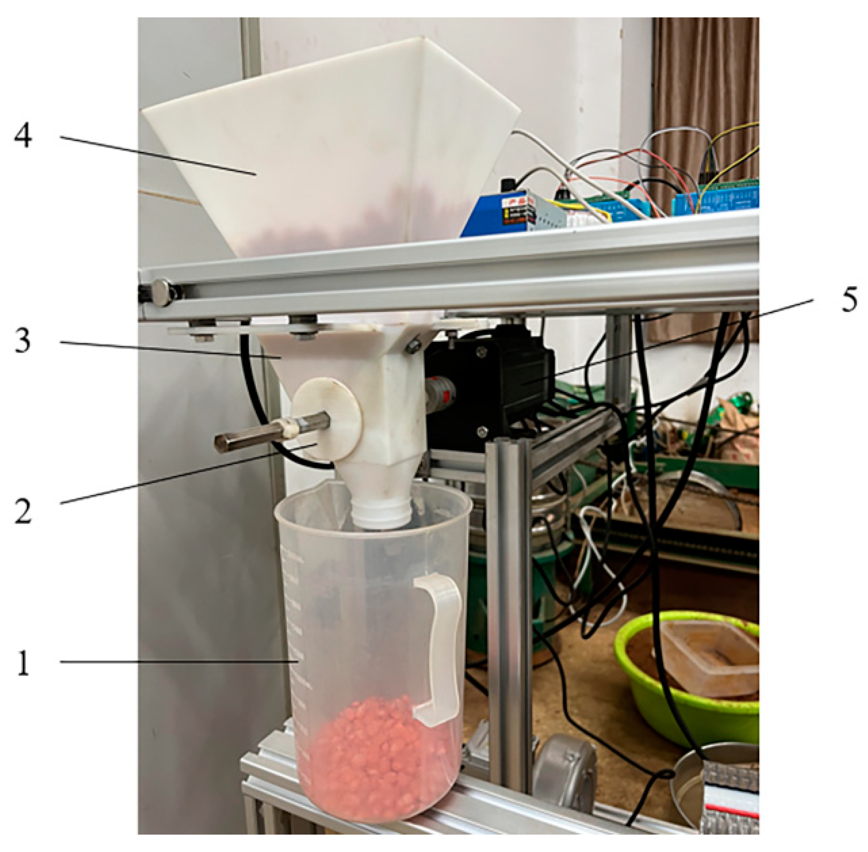
2.4. Seed Feeding Test

With the above analysis, when the groove wheel speed is constant, the groove tilt has a great influence on uniformity, while the influence of length is small. When the seed feeding rate is fixed, the length of the seed feeding wheel is 50 mm, so the bench test was carried out for the seed feeding wheel, whose spiral groove length l is 50 mm and the spiral groove inclinations ρ are 30°, 45°, and 90°. The seed feeding wheel with three structural parameters was processed using 3D printing technology, and the DSM IMAGE 8000 (DSM IMAGE 8000, Royal DSM, Co., LTD., Helen, Netherlands) resin material was selected as the processing material, as shown in Figure 7.
The stepper motor was used to drive the seed wheel. In order to ensure the accuracy of the seed wheel speed, the speed accuracy of the seed wheel drive motor was measured and verified. It can be concluded that under 15~35 rpm, the error rate of the actual speed of the seed wheel relative to the theoretical speed is less than 1%. Therefore, the speed accuracy of the seed wheel drive motor meets the requirements of the stand test.
Zhengdan 958 maize (Grain production Institute of Henan Academy of Agricultural Sciences, China) seed was selected as the experimental object, with a 1000-grain weight of 307 g, moisture content of 13%, and half horse tooth shape. The seed inlet and filling box were processed using 3D printing technology, and the bench was built, as shown in Figure 8. In the experiment, the seed wheel rotated at 25 rpm and the variation coefficient of seed flow was calculated by measuring seed flow every 3 s. Simultaneously, the fragmentation rate of the seeds collected in each experiment was measured, and the cracks in the seeds were determined to be fractured.

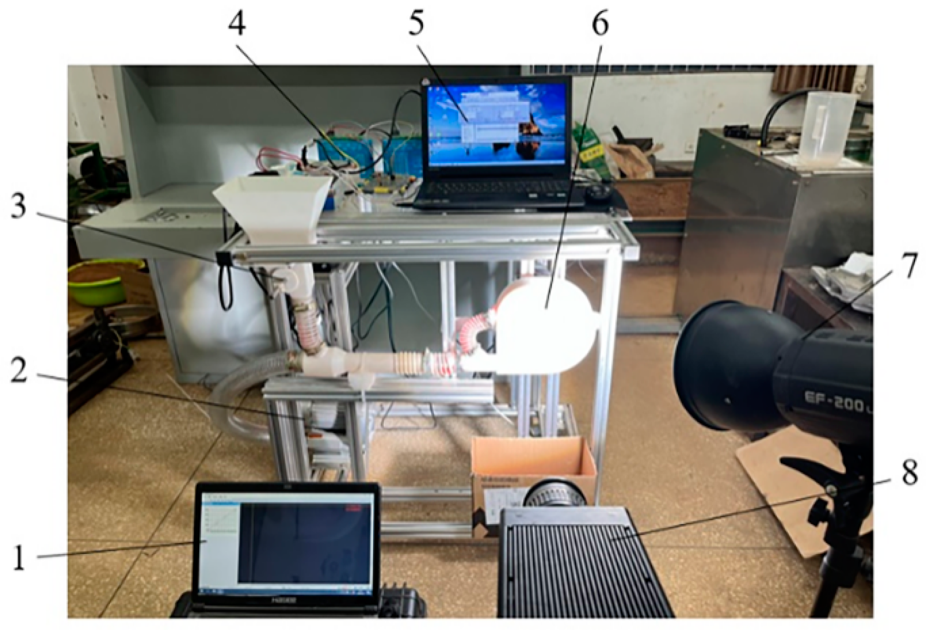
2.5. Performance Test of Seed Metering Device

The seed metering test bench connects the seed feeding device with the seed metering device, as shown in Figure 9. To test the effect of the seed feeding wheel on the seed metering performance, the straight groove seed feeding wheel and staggered symmetrical spiral groove seed feeding wheel were selected as experimental factors, and the experiment was carried out under 14 km/h operation speed. The corresponding seed feeding wheel speed was set to 25 rpm and the wind pressure was set to 8 kPa. A revealer branded high-speed camera was used to analyze the seeding process, and 1000 seeds were measured continuously, divided into 5 sections with 200 seeds in each section to count the pass rate and the miss rate.

3. Results and Discussion

3.1. Simulation Test Results and Analysis

To explore the influence of the spiral groove inclination angle and spiral groove length on the seed flow discharge uniformity of staggered symmetrical spirally grooved seed feeding wheel, according to the previous experimental exploration, taking the rotational speed of grooved wheel as 25 rpm as the initial condition, two-factor simulation experiments were carried out on the spiral groove inclination angle ρ and spiral groove length l of the staggered symmetrical seed feeding wheel structure. The spiral groove inclination angles ρ were set to 30°, 45°, 60°, 75°and 90°. The factors and levels of the simulation test are shown in Table 2, where the lengths of the spiral were set to three levels, 20 mm, 35 mm, and 50 mm, with the simulation time set to 20 s.
The uniformity of seed flow discharge was measured by the coefficient of variation of seed increment. The greater the coefficient of variation of seed increment is, the worse the uniformity of the seed flow discharge. The incremental variation coefficient of the collector seed is shown in the following:
μ = i = 1 n Q i N
ξ = i = 1 n ( Q i μ ) 2 N
S = ξ μ × 100 %
where μ is the average increase in seed in the collector; Qi is the increase in seed in the ith time period; ξ is the standard deviation of the increase in seed in the collector; N is the total number of time periods; and S is the coefficient of variation of the seed increment.
We set the stable working period of the seed wheel from 2 s to 18 s, counted the increase in seeds every 0.4 s during this period, and calculated the coefficient of variation of the increase in seed using Formula 6. Table 3 shows the results of the tests.
Table 3 shows that when the length of the spiral groove l is 50 mm and the inclination of the spiraling groove ρ is 45°, the minimum coefficient of variation of the increase in seed is 19.39%.

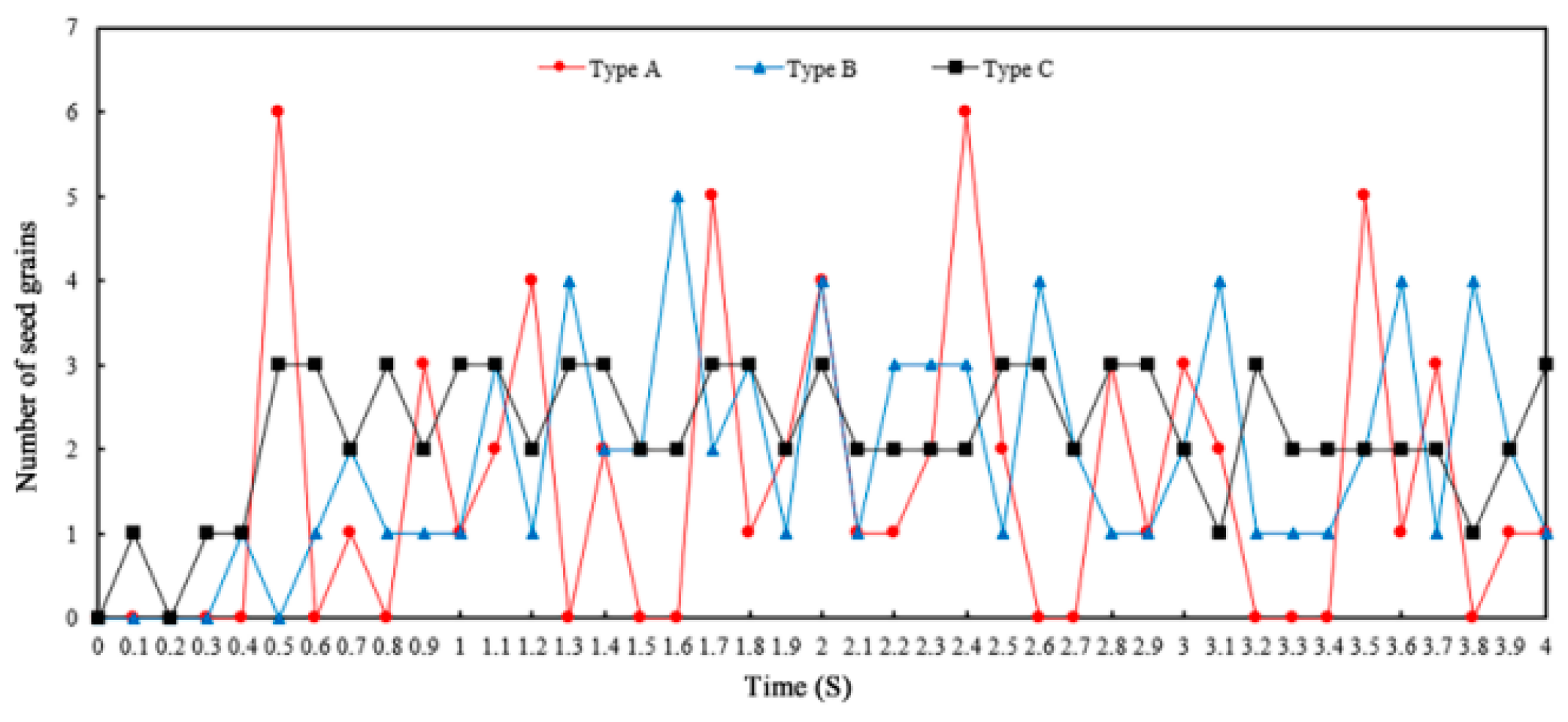
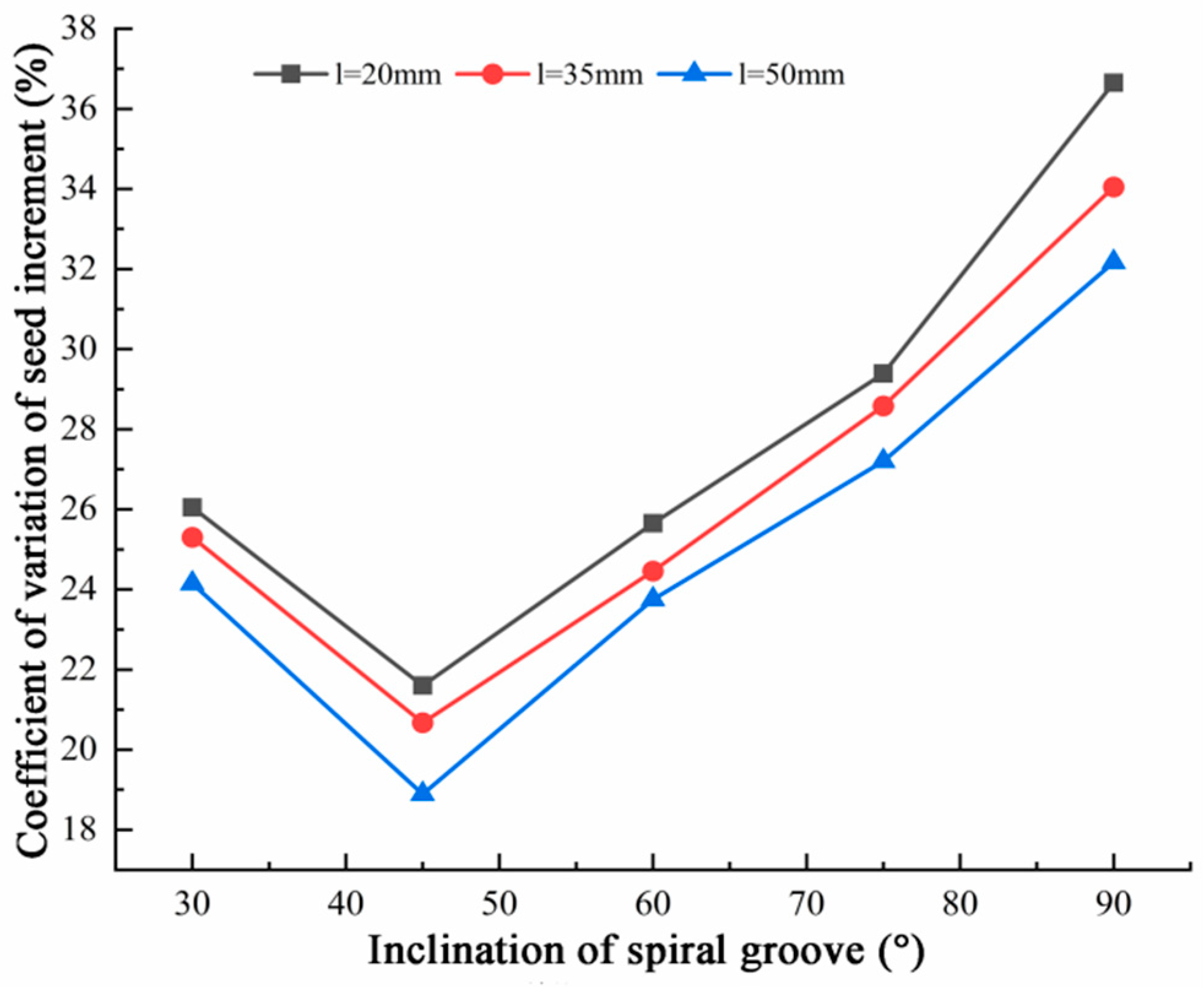
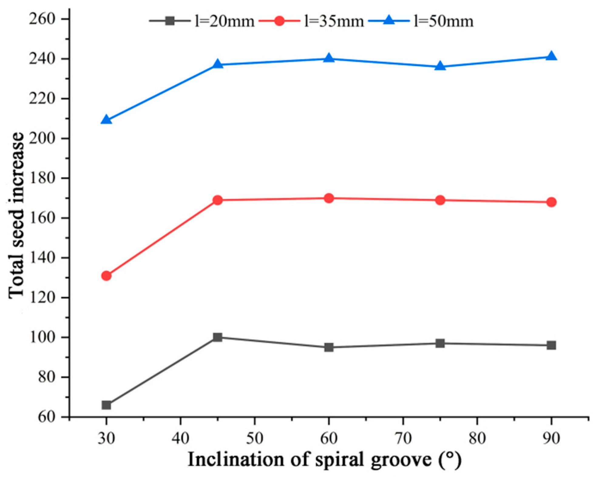
3.1.1. Effect of Groove Inclination on Seed Discharge Uniformity

To illustrate the influence of the change of structural parameters on the uniformity of seed discharge, the above test results are plotted as a dot-line diagram, as shown in Figure 10.
From the variation coefficient of the increase in seed and the inclination angle of the spiral groove, the variation trend of seed increase in the collector is similar to the increase in spiral groove inclination. The trend is that with the continuous increase in the inclination of spiral grooves, the coefficient of variation first decreases and then increases, and the coefficient is at its smallest when the inclination angle of the spiral grooves is 45°. When the inclination of the spiral groove is between 45° and 90°, with the increase in the inclination of the spiral groove and decrease in the inclination, the pulsation of the seed flow of the seed feeding wheel becomes more and more obvious, and the coefficient of variation of the seed increase becomes larger and larger. Hence, there is poor uniformity of seed discharges. When the spiral groove inclination angle is 90°, as in the traditional straight groove wheel, the seed flow discharge pulsation is at its largest, with uniformity being at its worst, and the coefficient of variation of the increase in seed is at its largest, generally more than 30%. When the inclination angle of the spiral groove is 30°, the grain variation coefficient is greater than 45°.
To explore the causes of this, the changing trend of the total increase in seed with the spiral groove inclination ρ in the period from 2 s to 18 s, when the seed feeding wheel works more smoothly, it was statistically analyzed, and the statistical results are shown in Figure 11.
The above figure shows that under the same spiral groove length when the spiral groove inclination angle decreases from 45° to 30°, the total seed decreases sharply, which is due to the fact that the spiral inclination angle is too small and the normal distance d between the spiral groove gaps is too small. As shown in Figure 12, it becomes more difficult for seeds to fill the grooves when the seed feeding wheel is working, and some seeds cannot be filled smoothly into the grooves. In addition, it also leads to an increase in the variation coefficient of increased seed size in the collector.

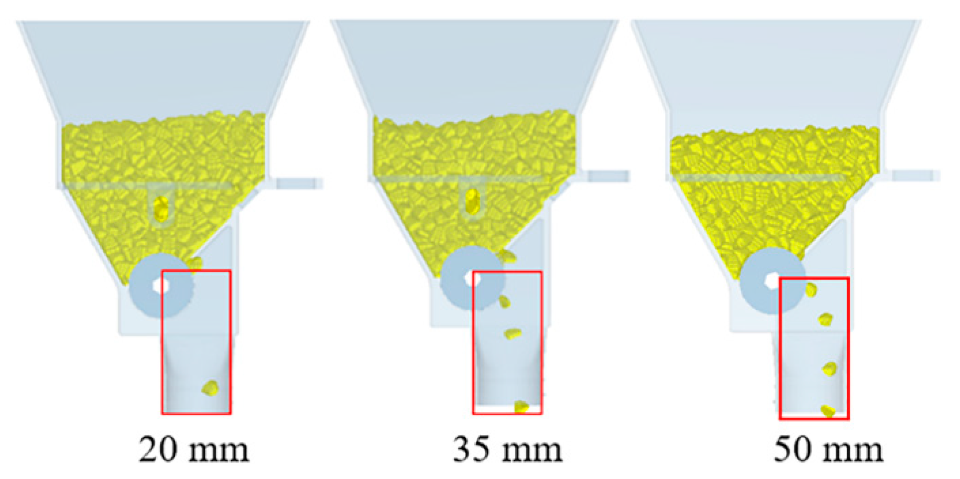
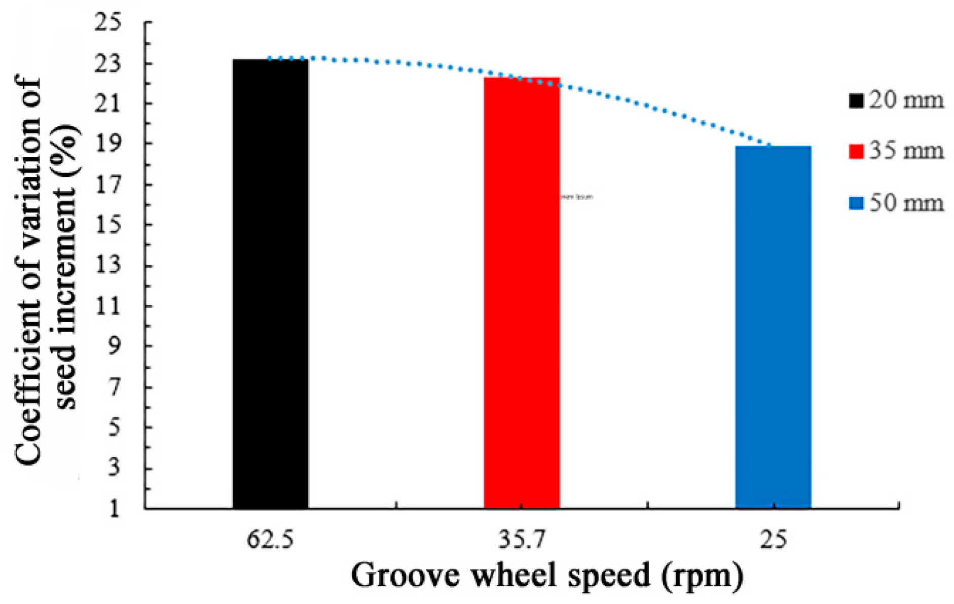
3.1.2. Effect of Groove Length on Seed Discharge Uniformity

Figure 10 shows that the coefficient of variation of seed increase in collector decreases with increasing spiral groove length l under different spiral groove tilt angles, but relative to the variation coefficient of seed increase caused by spiral groove inclination angle, the spiral groove length has little effect on the variation coefficient of seed increase. As can be seen from Figure 11, the amount of seed seeding increases with the length of the spiral groove because seed volume naturally increases with the speed and length of the groove.
Set a certain seed feeding rate, combined with previous experiments to ensure the seed feeding needs of the seed metering device for high-speed operation, and the seed feeding rate was set to 1050/min. The influence of the change in the seed feeding wheel speed caused by the change of spiral groove length on the uniformity of seed feeding was discussed. The inclination angle of the spiral groove is 45°, the lengths are 20 mm, 35 mm, and 50 mm, respectively, and the corresponding wheel speeds are 62.5 rpm, 35.7 rpm, and 25 rpm. The seed discharge status of the feeding wheel with different spiral groove lengths are shown in Figure 13. It can see that the seed flow discharge uniformity of the feeding wheel with spiral groove length of 50 mm is relatively better, and the seed distance is more uniform. When the length of the spiral groove is 35 mm, there is a phenomenon of leakage and a large distance between some seeds. At a spiral groove length of 20 mm, the leakage phenomenon is severe, and there is no seed discharge in a gap period.
For a more intuitive analysis of the influence of the rotation speed change on seed discharge uniformity caused by different spiral groove length, the relationship between rotational speed and seed increment coefficient of variation was determined, as shown in Figure 14.
The corresponding rotation speed can be found to be relatively fast when the length of the spiral groove is 20 mm, which shortens the filling time of seeds, leads to the leakage phenomenon, and the coefficient of variation is higher. As the length of the spiral groove increases, the speed of the pulley decreases gradually. When the corresponding speed of 50 mm was 25 rpm, the seed filling time increased, the seed discharge was relatively uniform and the coefficient of variation was relatively small. We selected the best length of pulleys in the seed feeding condition, 50 mm, in these three cases.

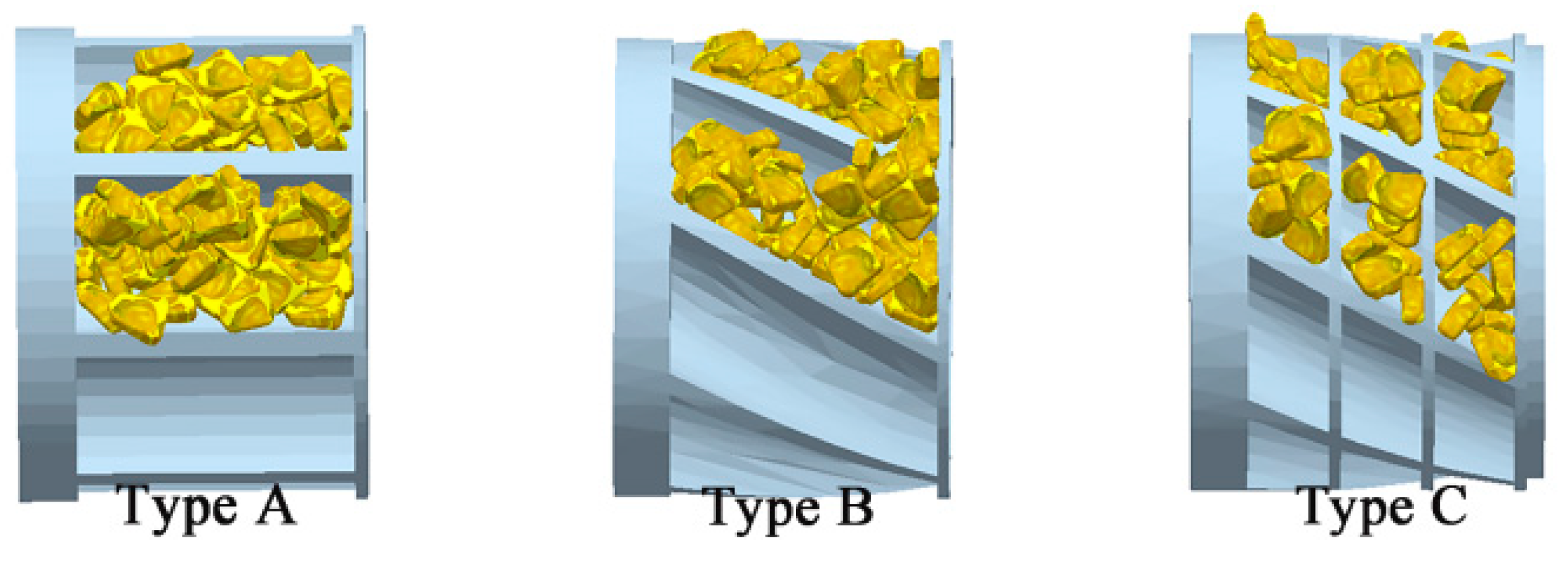
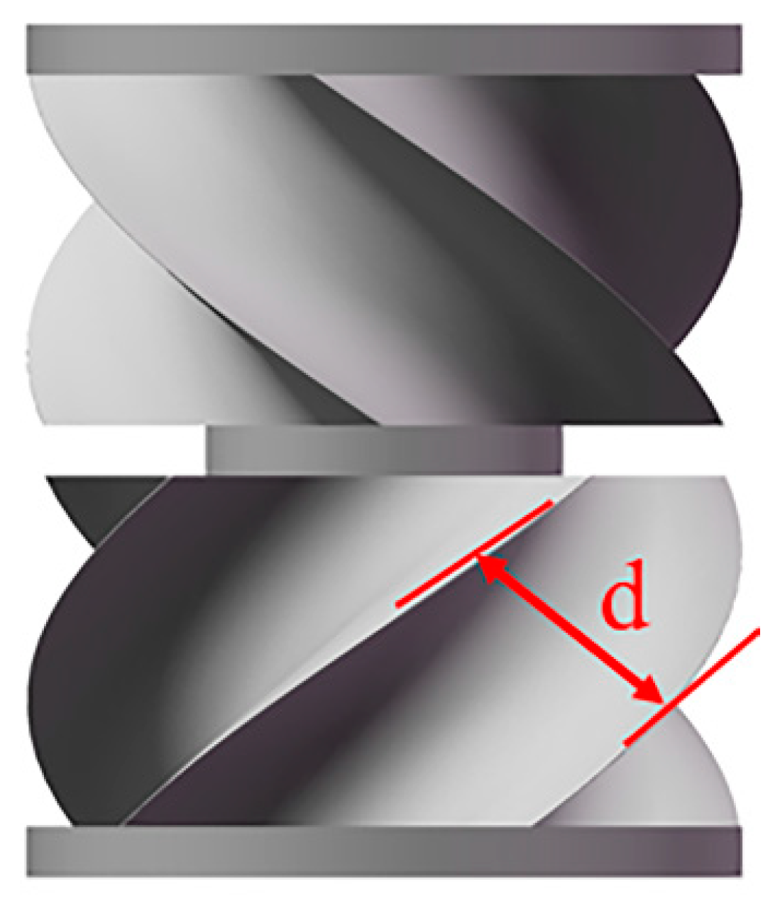
3.1.3. Effect of Spiral Groove Structure on Seed Motion

In order to further analyze the effect of the seed feeding wheel on seeds, three seed colors of different velocities were distinguished: forced layer, driving layer, and static layer. The seed velocities are graded from high to low in red, green, and yellow, as shown in Figure 15.
The average speed of seed extraction in each layer from 0 to 10 s is shown in Figure 16. It can be concluded that seed motion mainly occurs in the forced layer, and with the distance away from the grooved pulley, this motion gradually weakens.
Evident movement of the seeds in the forced layer makes it easy to squeeze and collide between the seed and the seed as well as between the grooved wheel and the husk, resulting in damage to the seeds in severe cases, which often occurs in the working process of the traditional straight grooved wheels [27]. For this reason, the seed of the forced layer was selected as the research object to compare the seed stress changes under the working conditions of the traditional straight groove wheel and designed seed feeding wheel, as shown in Figure 17. The results show that the groove force of the new seed wheel is significantly smaller than that of the traditional straight groove wheel.
The traditional straight groove wheel is often accompanied by the problem of serious seed damage, which is the problem of the groove wheel structure. The reason behind it is that after the seed is filled into the groove, with the rotation of the groove wheel, the seeds gather and rest, and phenomena such as extrusion and collision easily lead to seed breakage. On the other hand, in the staggered symmetrical spiral groove structure, the seeds in the groove are scattered and slide, which effectively avoids the occurrence of extrusion and collision. Therefore, the rate of seed damage can be reduced to a certain extent.

3.2. Seed Feeding Test

Table 4 shows the results of the platform test. According to the test results, the coefficient of variation of the seed flow discharge of the feeding wheel decreases at first and then increases with the increase in the spiral groove inclination angle ρ, and the coefficient is the lowest when the inclination angle ρ is 45°. The general trend of change is basically the same as the simulation results. The seed fragmentation rate also tends to decrease at first and then increase with the increase in the groove inclination angle, in which the breaking rate is the highest when the inclination angle is 90° and the minimum is 45°, which is due to the difference in seed force caused by the change in structure. This is mainly because at 30° the normal distance between grooves is too small, which leads to difficulty in seed filling, and the phenomena of seed sticking and seed entrapment will occur, which is basically in agreement with the previous analysis.
The accuracy of our theoretical analysis is verified by experiments. It is also proved that a staggering symmetric spiral groove feeding wheel can improve seed uniformity and reduce seed fragmentation. The optimization results show that the seed flow discharge uniformity is relatively improved when the spiral groove length l is 50 mm and the spiral groove inclination angle is 45°.

3.3. Seed Metering Test

Table 5 shows the results of the tests. The groove wheel structure has been shown to have a great influence on the seed leakage rate of the seed metering device, it has a higher leakage rate in the initial seed feeding stage, and the leakage rate gradually decreases with the increase in the number of seeds provided. The main reason for this is the large pulse phenomenon in the straight groove wheel seed feeding process, which leads to interrupted seed feeding, leading to severe seed leaks. The missing sowing phenomenon is decreased in the initial stage of the staggered symmetrical, spiral concave seed wheel, and the missing sowing phenomenon is eradicated with increased seed feeding. This is because the change in the structure of the seed wheel reduces the phenomenon of the seed feeding pulse. The seed feeding is continuous and sufficient to match the requirements of the seed filling of the high-speed rotating tray.
Through the above seed metering performance test, it was again verified that the designed staggered symmetrical spiral groove seed feeding wheel can effectively improve the seed feeding uniformity and improve the seed metering performance of the air-assisted high-speed precision seed metering device.

4. Conclusions

(1)
In order to ensure a uniform and continuous seed flow with an air-assisted high-speed precision seed metering device, a new staggered and symmetrical spiral fluted seed feeding wheel design was developed, and the comparative analysis showed that this structure has good applicability for the uniform seed discharge of maize.
(2)
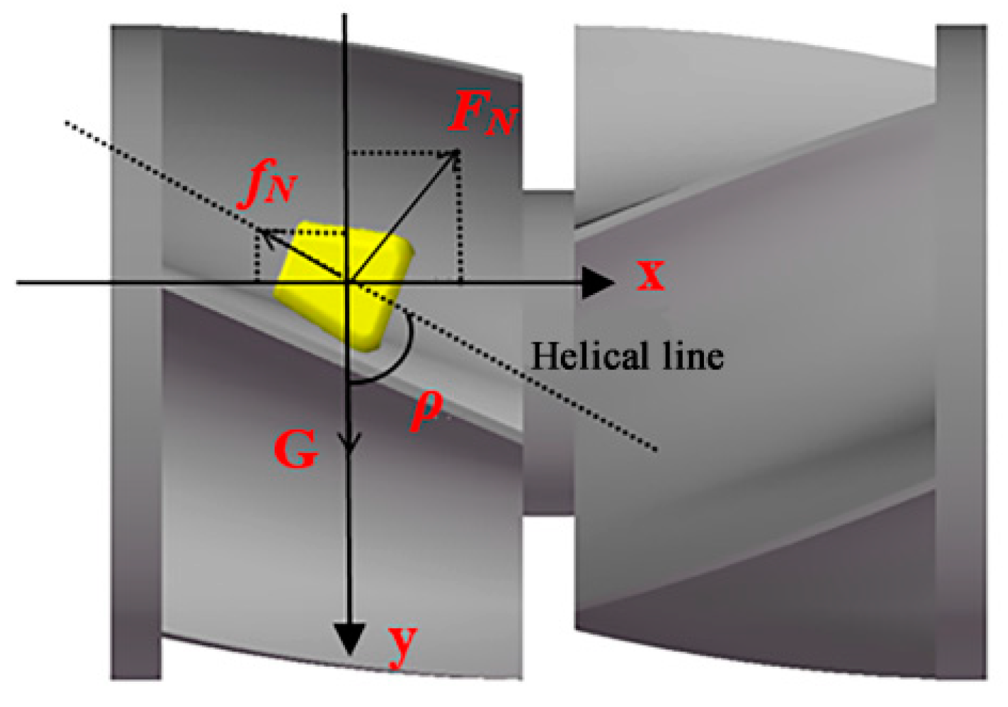
By analyzing the forces on the seeds in the grooves, the effect of the inclination of the spiral grooves on the variation of the forces on the seeds was determined. With a moderate inclination, the seeds changed from a relatively static state to an active sliding motion and the effect on the axial dispersion of the seeds in the grooves was enhanced.
(3)
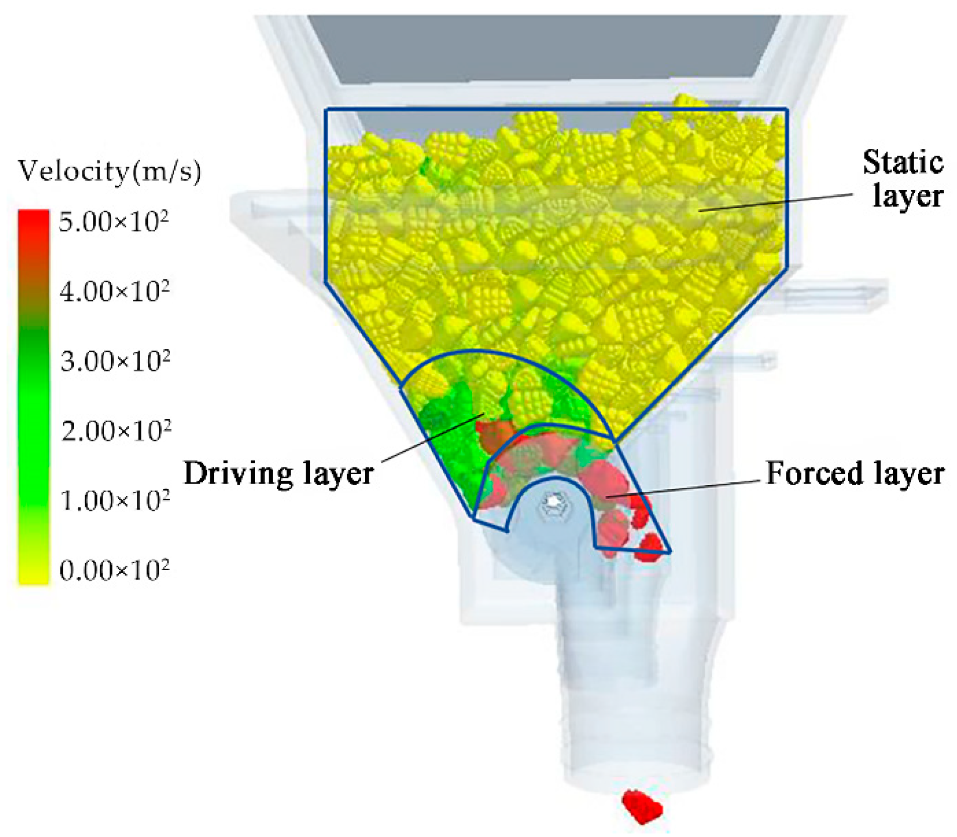
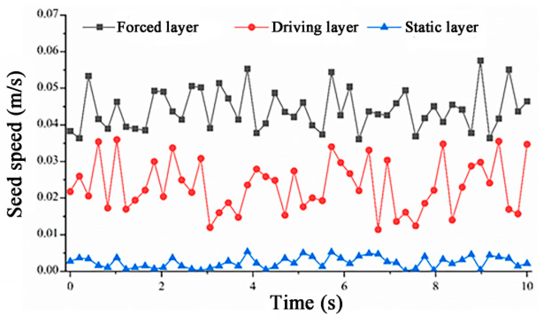
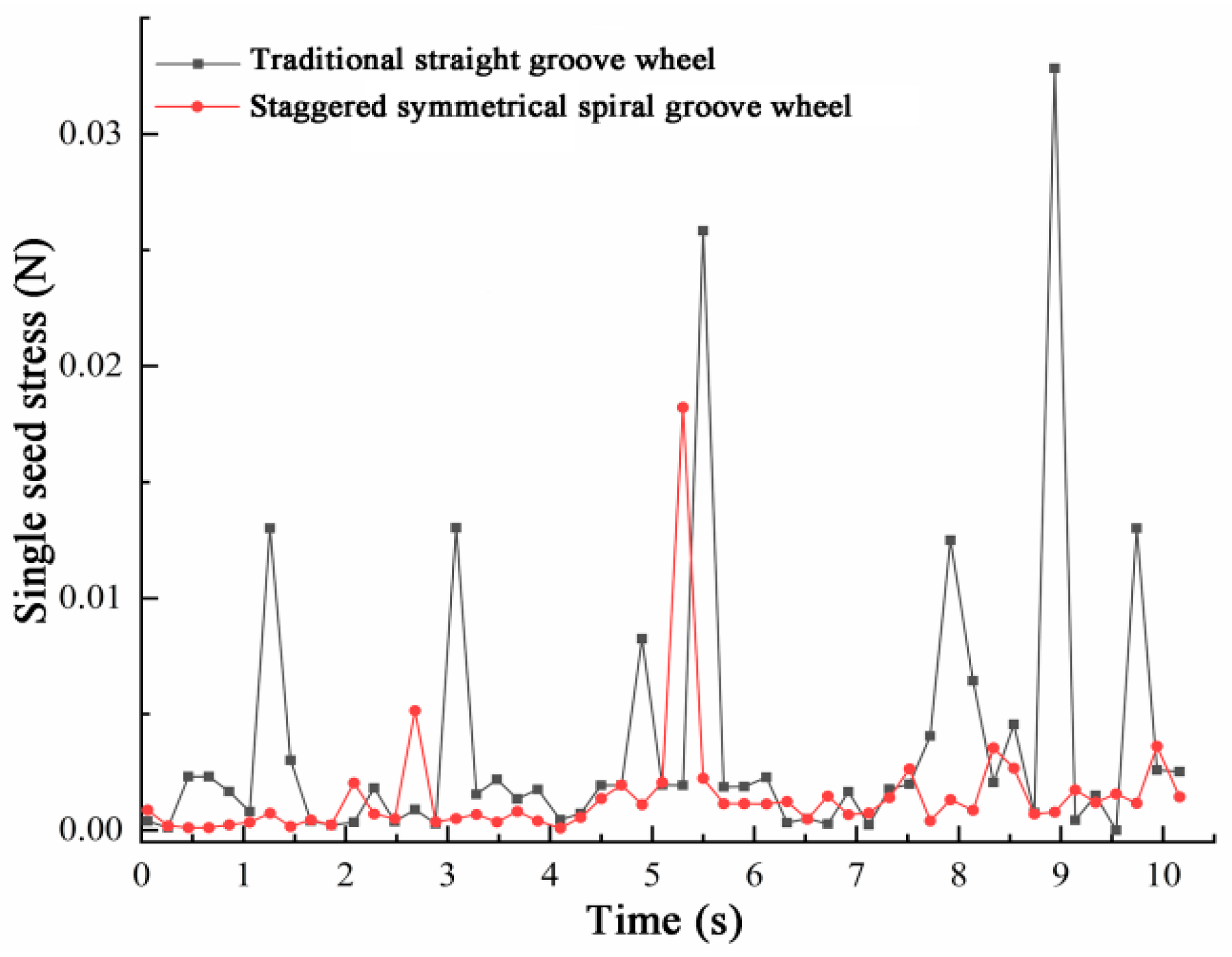
The discrete element method was used to analyze the seed motion in the staggered symmetrical spiral groove seed feeding wheel, and it was found that the seed velocity of the forced layer varied the most. The information on the force of seeds in the forced layer of the conventional straight groove and staggered symmetric spiral groove structures was extracted separately, and it was concluded that the force of seeds in the staggered symmetric spiral groove was smaller, which could effectively reduce the rate of seed breakage to certain extent and was verified by the bench test method.
(4)
A full-factor simulation test assessing the spiral recess inclination angle and spiral recess length was conducted, and it was concluded that the staggered symmetric spiral recess seed feeding wheel led to a greater improvement in terms of the uniformity of seed flow discharge, and the spiral recess length had little effect on the coefficient of variation of seed increase, while the change in the length of the spiral recess wheel affected the uniformity of seed feeding under the seed feeding rate of the adapted high-speed seeding volume, and it was concluded that the length was relatively uniform at 50 mm. The coefficient of variation of seed flow discharge pulsation was relatively small, 3.12%, when the length of spiral groove was 50 mm and the inclination angle of spiral groove was 45°, which was determined through a bench test. This structure can effectively improve the uniformity of seed flow, and the seed discharge performance test verified that this structure can improve the seed discharge performance of air-assisted high-speed precision seed metering devices.

Author Contributions

Writing—original draft preparation, X.G. and P.Z.; writing—review and editing, L.W. resources, J.L. and Y.H.; visualization, Y.X. All authors have read and agreed to the published version of the manuscript.

Funding

This work was supported by the National Key Research and Development Program of China, grant number 2021YFD2000404; the National Natural Science Foundation of China, grant number 52205283; the Modern Agricultural Engineering Key Laboratory at Universities of Education Department of Xinjiang Uygur Autonomous Region, grant number TDNG2022108; and the Bingtuan Science and Technology Program, grant number 2022CB001-06.

Institutional Review Board Statement

Not applicable.

Informed Consent Statement

Not applicable.

Data Availability Statement

The data presented in this study are available on request from the corresponding author.

Acknowledgments

This work was supported by the Support Plan for National key R & D projects (Project No. 2021YFD2000404), the National Natural Science Foundation of China (Project No. 52205283), the Modern Agricultural Engineering Key Laboratory at Universities of Education Department of Xinjiang Uygur Autonomous Region (Project No. TDNG2022108), and the Bingtuan Science and Technology Program (Project No. 2022CB001-06). The authors are grateful to anonymous reviewers for their comments.

Conflicts of Interest

The authors declare no conflict of interest.

References

  1. Yost, M.A.; Kitchen, N.R.; Sudduth, K.A.; Massey, R.E.; Sadler, E.J.; Drummond, S.T.; Volkmann, M.R. A long-term precision agriculture system sustains grain profitability. Precis. Agric. 2019, 20, 1177–1198. [Google Scholar] [CrossRef]
  2. Zhao, Y.S.; Gong, L.; Huang, Y.X.; Liu, C. A review of key techniques of vision-based control for harvesting robot. Comput. Electron. Agr. 2016, 127, 311–323. [Google Scholar] [CrossRef]
  3. Mikula, K.; Izydorczyk, G.; Skrzypczak, D.; Mironiuk, M.; Chojnacka, K. Controlled release micronutrient fertilizers for precision agriculture—A review. Sci. Total Environ. 2020, 712, 136365. [Google Scholar] [CrossRef]
  4. Kusumastuti, R.D.; Van Donk, D.P.; Teunter, R. Crop-related harvesting and processing planning: A review. Int. J. Prod. Econ. 2016, 174, 76–92. [Google Scholar] [CrossRef]
  5. O’Brien, P.; Daigh, A. Tillage practices alter the surface energy balance—A review. Soil Till. Res. 2019, 195, 104354. [Google Scholar] [CrossRef]
  6. Gao, X.J.; Zhou, Z.Y.; Xu, Y.; Yu, Y.B.; Su, Y.; Cui, T. Numerical simulation of particle motion characteristics in quantitative seed feeding system. Powder Technol. 2020, 367, 643–658. [Google Scholar] [CrossRef]
  7. Wang, J.W.; Qi, X.; Xu, C.S.; Wang, Z.; Jiang, Y.; Tang, H. Design Evaluation and Performance Analysis of the Inside-Filling Air-Assisted High-Speed Precision Maize Seed-Metering Device. Sustainability 2021, 13, 5483. [Google Scholar] [CrossRef]
  8. Shi, Y.Y.; Chen, M.; Wang, X.C.; Odhiambo, M.O.; Ding, W. Analysis and experiment of fertilizing performance for precision fertilizer applicator in rice and wheat fields. Trans. Chin. Soc. Agric. Mach. 2017, 48, 97–103. [Google Scholar] [CrossRef]
  9. Sun, J.F.; Chen, H.M.; Duan, J.L.; Liu, Z.; Zhu, Q.C. Mechanical properties of the grooved-wheel drilling particles under multivariate interaction influenced based on 3D printing and EDEM simulation. Comput. Electron. Agr. 2020, 172, 105329. [Google Scholar] [CrossRef]
  10. Tian, L.Q.; Wang, J.W.; Tang, H.; Li, S.W.; Zhou, W.Q.; Shen, H.G. Design and performance experiment of helix grooved rice seeding device. Trans. Chin. Soc. Agric. Mach. 2016, 47, 46–52. [Google Scholar] [CrossRef]
  11. Liu, C.B.; Zang, Y.; Luo, X.W.; Zeng, S.; Wang, Z.M.; Yang, W. Design and experiment of spiral grooved wheel for rice direct seeding machine. J. Shenyang Agric. Univ. 2016, 47, 734–739. [Google Scholar] [CrossRef]
  12. Jiang, M.; Liu, C.L.; Du, X. Research on continuous granular material flow detection method and sensor. Measurement 2021, 182, 109773. [Google Scholar] [CrossRef]
  13. Yi, M.G.; Zhang, S.M.; Liu, C.L.; Wen, Q. Design and experimental analysis of new type force feed for alfalfa sowing. J. Agric. Mech. Res. 2014, 36, 161–164. [Google Scholar] [CrossRef]
  14. Karayel, D.; Wiesehoff, M.; Merzi, A.O.; Müller, J. Laboratory measurement of seed drill seed spacing and velocity of fall of seeds using high-speed camera system. Comput. Electron. Agr. 2006, 50, 89–96. [Google Scholar] [CrossRef]
  15. Gao, X.J.; Xu, Y.; Yang, L.; Zhang, D.; Cui, T. Simulation and experiment of uniformity of venturi feeding tube based on DEM CFD coupling. Trans. Chin. Soc. Agric. Mach. 2018, 49, 92–100. [Google Scholar] [CrossRef]
  16. Lei, X.L.; Liao, Y.T.; Li, Z.D.; Cao, X.Y.; Li, S.; Wei, Y.P.; Liao, Q.X. Design and experiment of seed feeding device in air-assisted centralized metering device for rapeseed and wheat. Trans. Chin. Soc. Agric. Eng. 2015, 31, 734–739. [Google Scholar] [CrossRef]
  17. Correia, T.; Sousa, S.; Silva, P.; Dias, P.P.; Gomes, A. Sowing performance by a metering mechanism of continuous flow in different slope conditions. Eng. Agric. 2016, 36, 839–845. [Google Scholar] [CrossRef] [Green Version]
  18. Gao, X.J.; Xie, G.F.; Xu, Y.; Yu, Y.B.; Lai, Q.H. Application of a staggered symmetrical spiral groove wheel on a quantitative feeding device and investigation of particle motion characteristics based on DEM. Powder Technol. 2022, 407, 117650. [Google Scholar] [CrossRef]
  19. Ma, X.; Kuang, J.X.; Qi, L.; Liang, Z.; Tan, Y.; Jiang, L. Design and experiment of precision seeder for rice paddy field seedling. Trans. Chin. Soc. Agric. Mach. 2015, 46, 31–37. [Google Scholar] [CrossRef]
  20. Gao, X.J.; Cui, T.; Zhou, Z.Y.; Yu, Y.B.; Song, W. DEM study of particle motion in novel high-speed seed metering device. Adv. Powder Technol. 2021, 32, 1438–1449. [Google Scholar] [CrossRef]
  21. Maleki, M.R.; Jafari, J.; Raufat, M.; Mouazen, A.; Baerdemaeker, J. Evaluation of seed distribution uniformity of a multi-flight auger as a grain drill metering device. Biosyst. Eng. 2006, 94, 535–543. [Google Scholar] [CrossRef]
  22. Zeng, S.; Tang, H.T.; Luo, X.W.; Ma, G.H.; Wang, Z.M.; Zang, Y.; Zhang, M.H. Design and experiment of precision rice hill-drop drilling machine for dry land with synchronous fertilizing. Trans. Chin. Soc. Agric. Eng. 2012, 28, 12–19. [Google Scholar] [CrossRef]
  23. Geng, F.; Xu, D.Y.; Yuan, Z.L.; Yan, Y.M.; Luo, D.S.; Wang, H.S.; Li, B. Numerical simulation on fluidization characteristics of tobacco particles in fluidized bed dryers. Chem. Eng. J. 2009, 150, 581–592. [Google Scholar] [CrossRef]
  24. Altieri, G.; Renzo, G.; Genovese, F. Horizontal centrifuge with screw conveyor (decanter): Optimization of oil/water levels and differential speed during olive oil extraction. J. Food Eng. 2013, 119, 561–572. [Google Scholar] [CrossRef]
  25. Jin, M.; Zhang, M.; Wang, G.; Liang, S.N.; Wu, C.Y.; He, R.Y. Analysis and simulation of wheel-track high clearance chassis of rape wind rower. Agriculture 2022, 12, 1150. [Google Scholar] [CrossRef]
  26. Pan, S.Q.; Zhao, Y.X.; Jin, L.; Qu, G.B.; Tian, G. Design and experimental research of external grooved wheel fertilizer apparatus of 2BFJ-6 type variable. J. Chin. Agric. Mech. 2016, 37, 40–42. [Google Scholar] [CrossRef]
  27. Liu, Q.W.; Cui, T.; Zhang, D.X.; Yang, L.; Wang, Y.X.; He, X.T.; Wang, M.T. Design and experiment of seed precise delivery mechanism for high-speed planter. Int. J. Agric. Biol. Eng. 2017, 11, 81–87. [Google Scholar] [CrossRef]
Figure 1. Air-assisted high-speed precision seed metering device. 1. Seed feeding device; 2. venturi tube; 3. seed metering device; 4. seed inlet; 5. seed filling box; 6. seed feeding wheel.
Agriculture 12 01951 g001
Figure 2. Structure schematic diagram of feeding wheel. Type A is a straight groove-type seed wheel, Type B is a spiral groove-type seed wheel, and Type C is a grid groove-type seed wheel.
Agriculture 12 01951 g002
Figure 3. Variation of the number of discharged seeds from the feeding device with time for different types of wheels.
Agriculture 12 01951 g003
Figure 4. Structure diagram of staggered symmetrical spiral grooved seed feeding wheel.
Agriculture 12 01951 g004
Figure 5. Sliding seed force analysis.
Agriculture 12 01951 g005
Figure 6. Three-dimensional model of feeding wheel with different parameters.
Agriculture 12 01951 g006
Figure 7. Three-dimensional printing feeding wheels.
Agriculture 12 01951 g007
Figure 8. Bench test device. 1. Seed collection box; 2. seed feeding wheel; 3. seed filling box; 4. seed inlet; 5. stepper motor.
Agriculture 12 01951 g008
Figure 9. Air-assisted high-speed precision seed metering system test bench. 1. Computer I; 2. fan; 3. seed feeding wheel; 4. control module; 5. computer II; 6. seed rower; 7. fill light; 8. high-speed camera.
Agriculture 12 01951 g009
Figure 10. Effect of spiral groove inclination on variation coefficient of seed increment.
Agriculture 12 01951 g010
Figure 11. Effect of spiral groove inclination change on seed increment.
Agriculture 12 01951 g011
Figure 12. Diagram of normal distance between spiral groove openings.
Agriculture 12 01951 g012
Figure 13. Comparison of uniformity of discharged seed for different lengths of grooved wheels.
Agriculture 12 01951 g013
Figure 14. Effect of rotating speed on the coefficient of variation of seed quantity due to the change in wheel length.
Agriculture 12 01951 g014
Figure 15. Schematic diagram of seed movement in the device.
Agriculture 12 01951 g015
Figure 16. Variation of seed velocity in different layers.
Agriculture 12 01951 g016
Figure 17. Force comparison of seed in different feeding wheels.
Agriculture 12 01951 g017
Table 1. Physical and mechanical characteristic parameters required for simulation.
SubsetsParametersNumerical Value
Maize grain attributePoisson’s ratio0.40
Shear modulus (Pa)1.37 × 10⁸
Density (kg/m3)1197
Seed wheel device attributePoisson’s ratio0.50
Shear modulus (Pa)1.77 × 10⁸
Density (kg/m3)1180
Collision recovery coefficientSeed–seed0.18
Seed–feeding wheel0.71
Static friction coefficientSeed–seed0.03
Seed-feeding wheel0.46
Dynamic friction coefficientSeed–seed0.01
Seed–feeding wheel0.09
Other parametersGravity acceleration (m/s2)9.81
Table 2. Two-factor test factor and level table.
FactorHorizontal
12345
Spiral groove inclination ρ (°)3045607590
Spiral groove length l (mm)203550
Table 3. Two-factor simulation test results.
Serial NumberSpiral Groove Length (mm)Spiral Groove Inclination ρ (°)Coefficient of Variation of Seed Increment (%)
1203027.33
2204520.92
3206026.25
4207528.89
5209037.53
6353026.12
7354522.05
8356025.34
9357528.15
10359033.58
11503024.55
12504519.39
13506024.25
14507526.80
15509031.88
Table 4. Pulsating variation coefficient and breakage rate of seed flow discharge under different spiral groove inclination angles.
Groove ObliquityTest NumberCoefficient of Variation (%)Average of Coefficient of Variation (%)Breakage Rate (%)
ρ = 30°15.726.881.92
25.33
35.69
ρ = 45°12.283.120.69
22.13
32.08
ρ = 90°114.3716.323.12
213.83
313.46
Table 5. Effect of groove wheel structure on seeding performance.
Geneva TypeIntervalQualified Rate (%)Missed Seeding Rate (%)
Straight slotted seed feeding wheel0~20083.017.0
200~40089.06.0
400~60091.53.0
600~80091.02.0
800~100092.02.0
Spiral groove type seed feeding wheel0~20087.512.0
200~40089.57.0
400~60091.02.5
600~80092.02.0
800~100091.52.5
Gridded slot seed feeding wheel0~20090.04.0
200~40089.55.5
400~60091.52.0
600~80091.02.0
800~100091.52.5
Staggered symmetrical spiral groove type seed feeding wheel0~20092.52.0
200~40093.00.5
400~60091.50.0
600~80092.50.0
800~100092.00.0
Publisher’s Note: MDPI stays neutral with regard to jurisdictional claims in published maps and institutional affiliations.

