1. Introduction
A tomato picking lifting platform is a kind of intelligent agricultural equipment mounted on the chassis of tomato picking robot to assist in picking. It is used to install a picking manipulator and sensors, which have the functions of automatic lifting, leveling, accurate parking at the specified height, and so on. The lifting platform is the key component of the picking robot, which can increase the picking range of the robot, give full play to the function of the mechanical arm, and speed up the picking speed. The performance of the lifting platform directly affects the tomato picking effect [
1,
2].
At present, most of the research on automatic tomato picking robots focuses on the picking robot arm, focusing on the end effector design [
3,
4,
5,
6,
7], positioning, and identification of tomato fruits and stalks [
8,
9,
10,
11,
12], etc. For example, KNODO et al. in Japan adopted a Mitsubishi RH-6SH5520 four-degree-of-freedom industrial robot. The developed tomato picking robot uses photoelectric sensor to position the tomato stalks, and uses single-chip microcomputer to control the blade to cut the positioned fruit stalks. The tomato picking robot takes 15 s to pick a single bunch of tomatoes, with a success rate of 50%. However, in the actual agricultural environment, under the influence of the picking site, fruit shading, fruit intensive growth, and so on [
13,
14,
15,
16], the mechanical arm cannot work in the best position in many cases, and the mechanical arm that can adjust its position and trajectory in real time demonstrates some problems, such as large volume, complex structure, high weight, large inertia, and high manufacturing cost. A picking lifting platform can be used as a supplement to reduce the difficulty and cost of mechanical arm design. However, the existing automatic picking and pruning lifting platforms are aimed at facilitating high-altitude operations and often need to carry people. In other words, the technical indicators of the existing lifting platforms are mainly the lifting height and load; there are certain requirements for the torsion angle of the lifting platform, but almost no requirements for the accuracy of angle adjustment [
1,
2]. Therefore, it is of great value to develop a lifting platform with the functions of automatic lifting, leveling, accurate parking, etc., for the realization of tomato picking automation.
China is the country with the largest tomato planting area and the largest total production in the world. The annual output of tomatoes can reach about 50 million tons [
17], and it still shows a trend of continuous increase. According to the monitoring project statistics, in 2018, the tomato cultivation area in China was 1.109 million hectares, and the yield was about 64.832 million tons [
18,
19]. The expanding greenhouse area [
20] of tomato facilities requires more labor, but with the increasing labor cost, there is a structural shortage of agricultural labor [
21,
22,
23]. At the same time, the operating environment of facility greenhouse has the characteristics of high temperature, high humidity, closed, and narrow [
24,
25], and the problems of high labor intensity and low degree of mechanization and automation of operation have become increasingly prominent [
26,
27]. Picking is one of the most time-consuming, laborious, and time-sensitive links in tomato production [
8]. The labor demand in the picking process accounts for about 50% of the whole planting process, while the cost accounts for about 25–33% of the cost. Therefore, the demand for picking institutions suitable for greenhouse environment is increasing.
In this paper, based on the six-degree-of-freedom (6-DOF) motion platform [
28,
29,
30], a lifting platform suitable for the tomato picking robot arm is studied, which can ensure that the picking robot arm can continue picking tomato fruits at another height after picking them at a certain height, and keep the stability of the robot arm during the lifting process to prevent the whole machine from turning over. In addition, the lifting platform also has a certain angle automatic adjustment function to ensure that the mechanical arm, sensors, and other components on the lifting platform can work stably when the chassis starts and brakes. The authors have made certain achievements in the fields of greenhouse tomato and kiwi picking manipulator design, chassis design, picking robot vision system design, etc. Several studies published in recent years lay a solid foundation for this research [
31,
32].
2. Materials and Methods
2.1. Analysis of Tomato Planting Environment and Picking Process
The lifting platform of tomato picking designed in this paper is mainly aimed at tomato picking in solar greenhouse.
Figure 1 shows the tomato planting mode in solar greenhouse, with single ridge and double rows [
33]. The tomato plant spacing is 30 cm, the effective plant height is 30~160 cm, the robot operation lane, that is, the width of tomato ridge spacing is 80 cm, and the width of irrigation ditch is 20 cm. The growing areas of tomato fruits are scattered and the height difference is large; therefore, the maturity of tomatoes with the same height is basically the same. Robots need mechanical arms with different lengths and positions when picking tomato fruits with different heights, so the picking process usually starts from the roots and then the height is raised by the lifting platform in turn.
The schematic diagram of the tomato picking robot chassis size and structure shown in
Figure 2a,b is the schematic diagram of picking robot operation scope. In order to facilitate the robot to travel normally in the operation lane and avoid touching the tomato ridge, the tomato picking lifting platform designed in this paper must meet the design size of the robot chassis and mechanical arm, so as to be suitable for picking operations. In order to facilitate the robot to travel normally in the operation lane and avoid touching the tomato ridge, 10 cm spaces should be reserved at the left and right sides of the operation lane to meet the walking requirements of the chassis. The selected chassis size is 60 cm×80 cm, and the total height of the chassis is 45 cm. The picking manipulator is a 6-DOF manipulator, which is fixed on the lifting platform by a rotatable moving platform. The mechanical arm is divided into two arms, which can reach about 60 cm when fully extended.
According to the parameters and design requirements of the above-mentioned picking robot, such as chassis height, picking range of mechanical arm, effective plant height of tomato, etc., the basic parameters of the lifting platform are determined. The initial height of the picking lifting platform is preliminarily designed to be 65 cm, which can meet the working requirements of 10° change in pitch angle, 15 cm lifting and load within 50 kg [
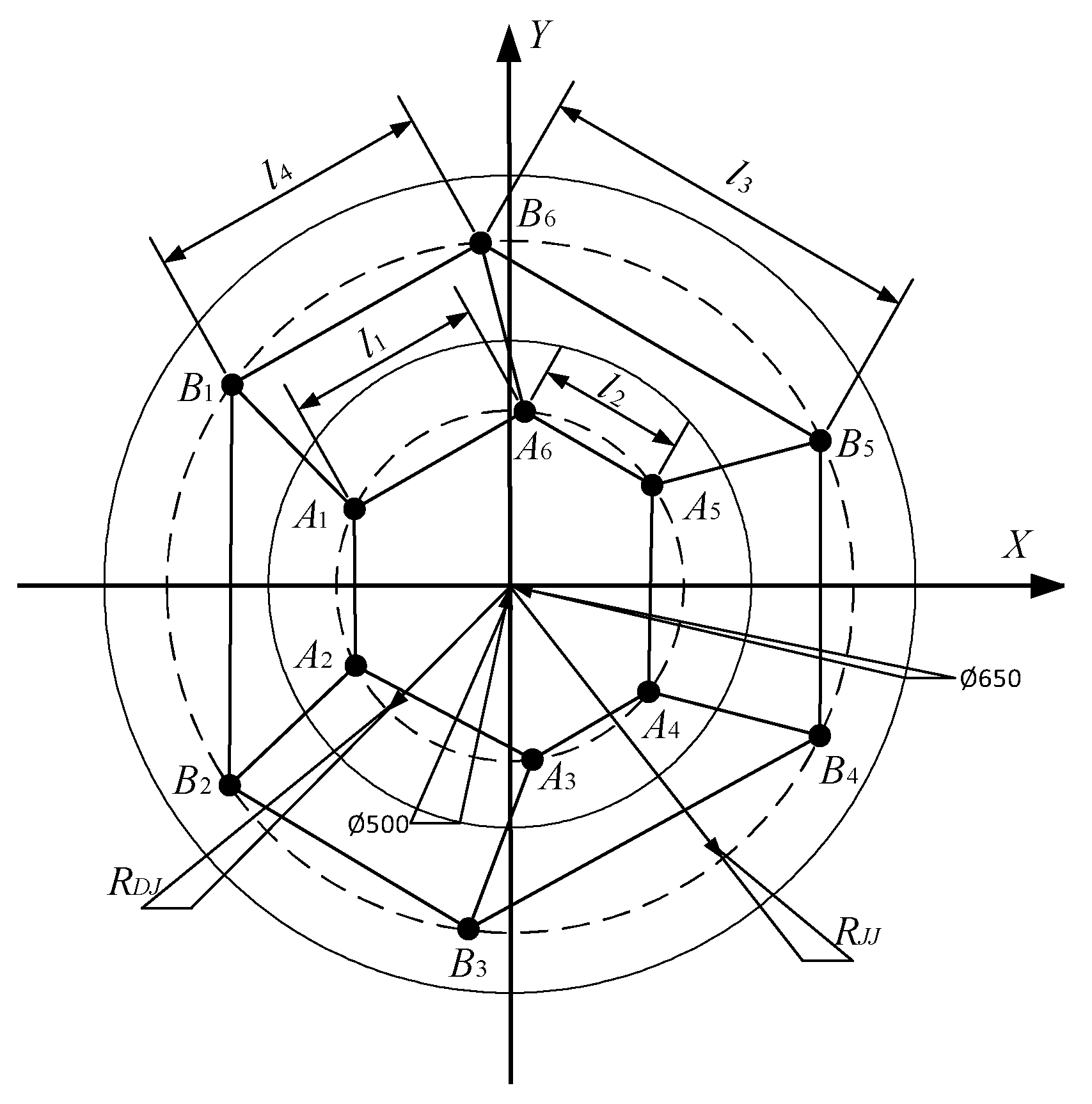
33]. The designed upper platform is a moving platform, where picking manipulator and other sensors are installed, and the hinge point is a hexagon symmetrical about
x axis; The lower platform is a static platform, which is fixed on the chassis of tomato picking robot. The upper and lower platforms adopt 50° and 70° distribution angles. When the electric cylinder is installed, the short side of the upper platform corresponds to the long side of the lower platform. The specific dimensions and hinge points of the upper and lower platforms are shown in
Figure 3.
2.2. Space Attitude Position Analysis
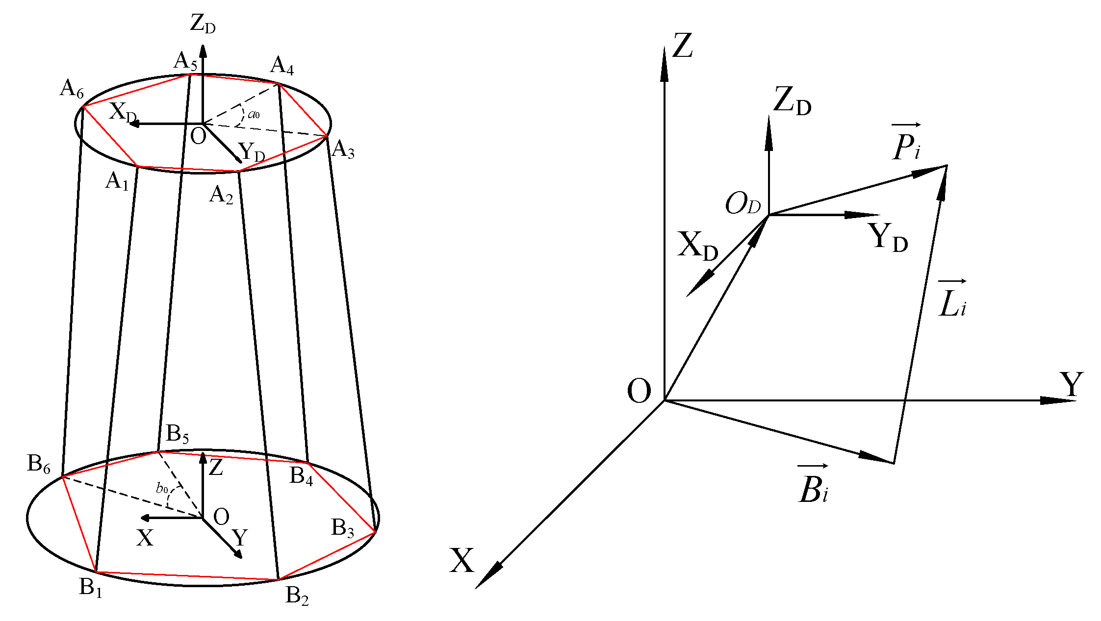
The spatial relationship between the upper and lower platforms is shown in
Figure 4.
It is assumed that the coordinate system of the lower platform with constant position is
, and the coordinate system
of the upper platform is the moving platform. Then,
where
is the vector from the origin
to the
-th hinge point of the upper platform in the fixed coordinate system when it is at any position. When
is the initial position, the vector from the origin
to the
-th hinge point of the upper platform is in the fixed coordinate system.
is the vector from the original point to the -th hinge point of the lower platform in the static coordinate system.
Where and is known, is in the initial position, and can be converted by in different pose states.
2.3. Simulation Analysis of Tomato Picking Lifting Platform
We established the lifting platform model in SolidWorks, and checked whether the designed size was reasonable, and whether there was movement interference with other mechanisms when the platform moved to its limit position. In addition, as the electric cylinder is the weak point of the 6-DOF platform, a three-dimensional model of the driving motor and the electric cylinder was built, the 6-DOF motion of the platform was simulated, and the simulation curves of displacement, velocity and acceleration were obtained to verify the rationality of the mechanical structure design of the platform, which provides a theoretical basis for the follow-up optimization and strength check.
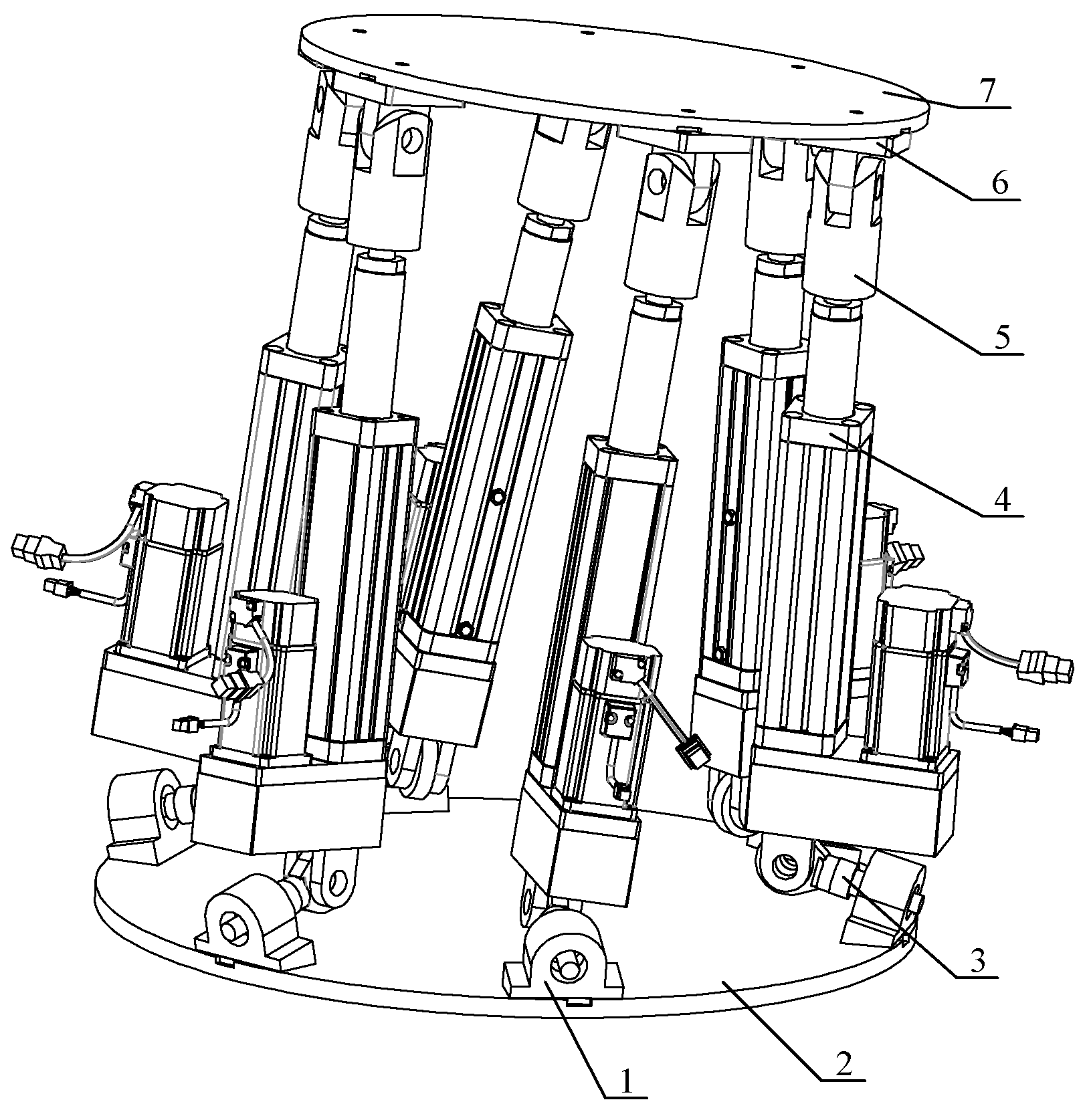
The three-dimensional model of the 6-DOF lifting platform established in SolidWorks software (Dassault Systèmes Co., Paris, France) is shown in
Figure 5. In order to ensure the normal simulation, the ball screw structure inside the electric cylinder is simplified and omitted, and only the external shape (cylinder liner) and piston rod are retained. During assembly, the cylinder liner and piston rod were set to be screwed to restore the actual movement process. The relative displacement sensor, force sensor, and inertia sensor were installed inside and outside the cylinder.
2.4. Rationality Analysis of Platform Design at the Limit Position
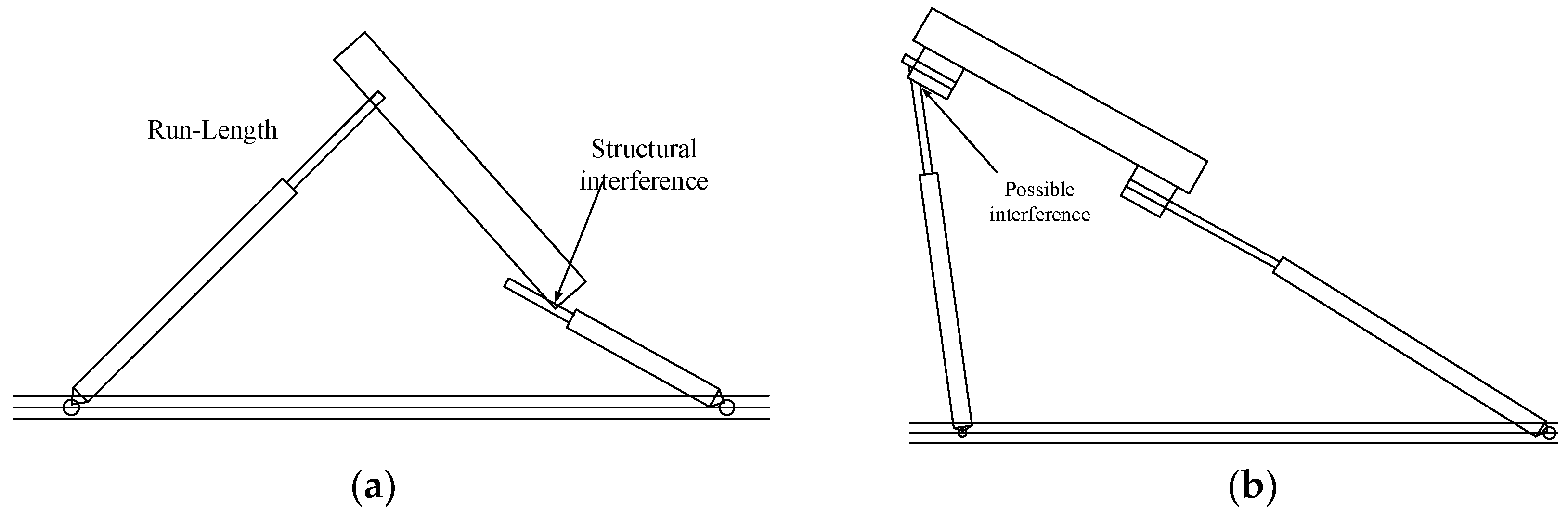
In order to avoid the movement interference caused by unreasonable mechanical structure design in the process of platform lifting or leveling, the possible interference of 6-DOF platform in various postures and postures should be checked, including the range of articulation, whether the electric cylinder interferes with the upper platform when moving, and whether the electric cylinder interferes with the support of the lower platform.
Figure 6 is a schematic diagram of the extreme pose of interference. As shown in
Figure 6a, when the left electric cylinder reaches the limit length, the piston rod of the right electric cylinder may contact with the upper platform to cause interference;
Figure 6b shows that when the rotating ears of the upper platform support of the electric cylinder are too short, the piston rod of the electric cylinder may interfere with the fixed ear.
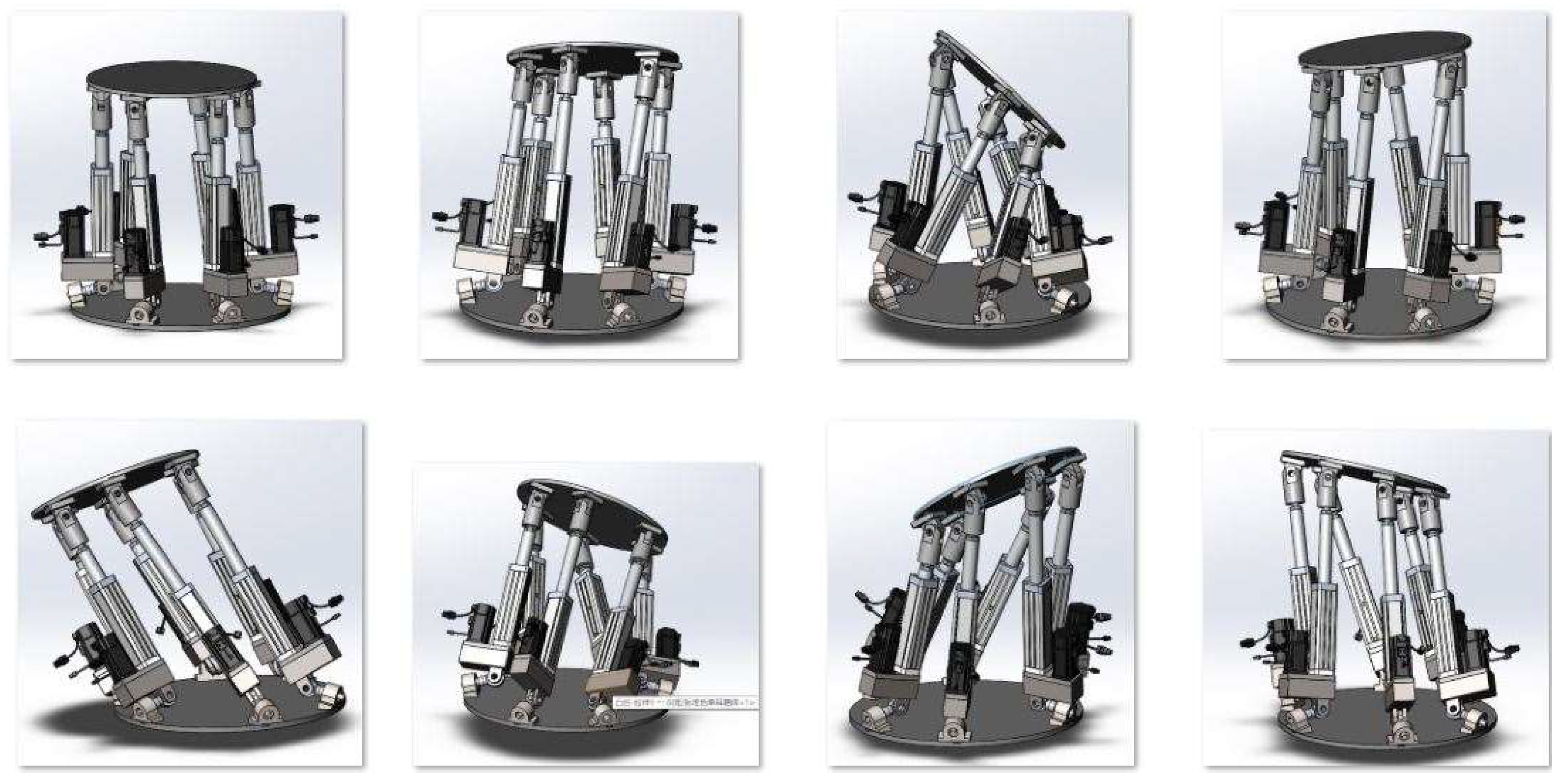
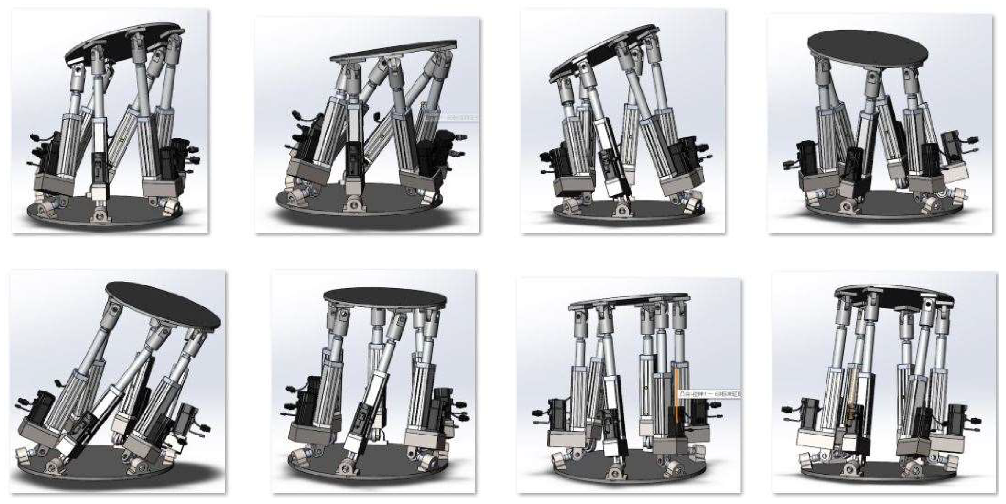
According to the above analysis, it is necessary to check whether there is structural interference in 16 extreme poses of the tomato picking lifting platform that meet the working requirements. The check results are shown in
Figure 7. The results show that there is no such interference, and the parameter design of the three-dimensional model meets the requirements, thereby completing the static simulation of the lifting platform.
The 16 extreme postures of tomato picking lifting platform that meet the working requirements consist of: the maximum and minimum telescopic distance in vertical, longitudinal and transverse directions, the maximum and minimum rotation angles in pitch, roll and yaw angles, and four combined extreme postures. For example, the third and fifth pictures in the first two rows show the maximum rotation angle of the platform, and the other six pictures show the maximum displacement of the platform. The last two rows show the maximum rotation angle and combined limit pose of the platform.
2.5. Kinematics Simulation
Firstly, through theoretical analysis, the spatial coordinate system is established by using the inverse position solution, and the spatial pose angle of the lifting platform is defined, so that the relationship between the expansion and contraction of the piston rod and the coordinate change is obtained.
The lower platform of the lifting platform is always horizontal, and the posture of the upper platform will change. The coordinate system of the lower platform is a fixed coordinate system, which is the coordinate system of the upper platform. The origin of its coordinates is relative to the coordinates of the fixed reference system, when the initial position.
It is assumed that the pose angle of the 6-DOF platform is represented by yaw angle, pitch angle and yaw angle. The pose state of the moving coordinate system starts from the initial position, first rotates around the z axis to generate yaw angle, then rotates around the y axis to generate pitch angle, and finally rotates around the x axis to generate yaw angle, so as to obtain pose information.
Rotation coordinate transformation matrices around the
x,
y and
z axes are expressed as follows:
is a rotation transformation matrix; it can be calculated as follows:
Take the derivative of time t and obtain the solution.
where
,
,
are anti-symmetric matrices.
,
,
.
Therefore, the relationship between the articulated point speed of the moving platform
and the platform speed
is as follows:
where
.
The relationship between the telescopic speed of each electric cylinder
and the corresponding articulated point speed of the upper platform
is as follows:
where
.
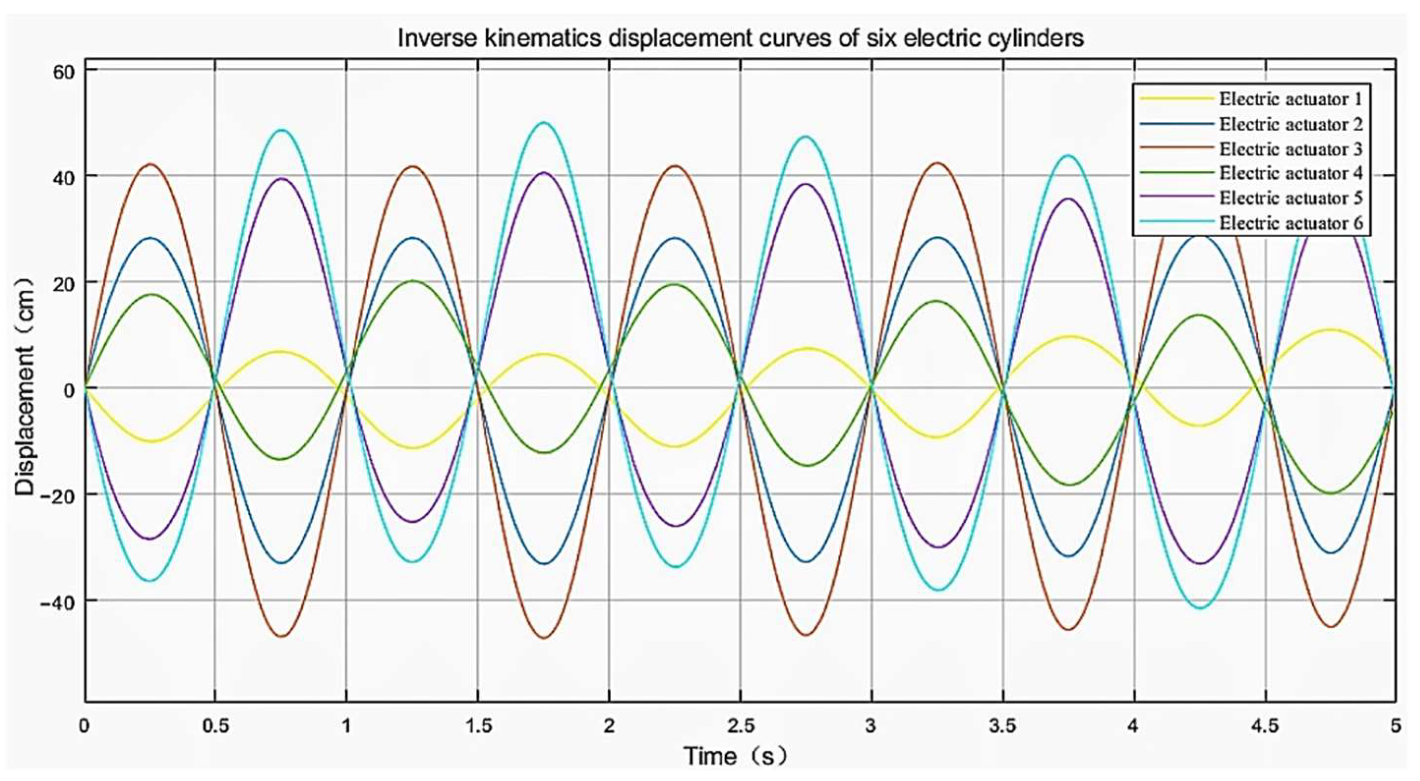
According to the theoretical analysis results and platform parameters of the platform, the Simulink module of MATLAB software (MathWorks Inc., Natick, USA) is used to model and simulate the inverse kinematics equation, and the expansion and contraction of the piston rod in the electric cylinder is obtained. Based on the analysis of the picking environment, the picking platform needs to rotate around the
x,
y, and
z axes by ±10°, that is, the minimum pitch angle of the platform is 10°. The motion signal of the upper platform is defined as cosine signal, and the cosine function is to make the platform rotate around the
x and
y axes. The telescopic curves of six electric cylinders obtained by Simulink inverse solution are shown in
Figure 8. It can be seen from the figure that the maximum elongation of the piston rod of the electric cylinder is 57.8 mm and the contraction is −47.4 mm. Thus, the simulation signal of continuous motion is obtained, which provides the driving function for the dynamic simulation of the three-dimensional model.
2.6. Dynamics Simulation
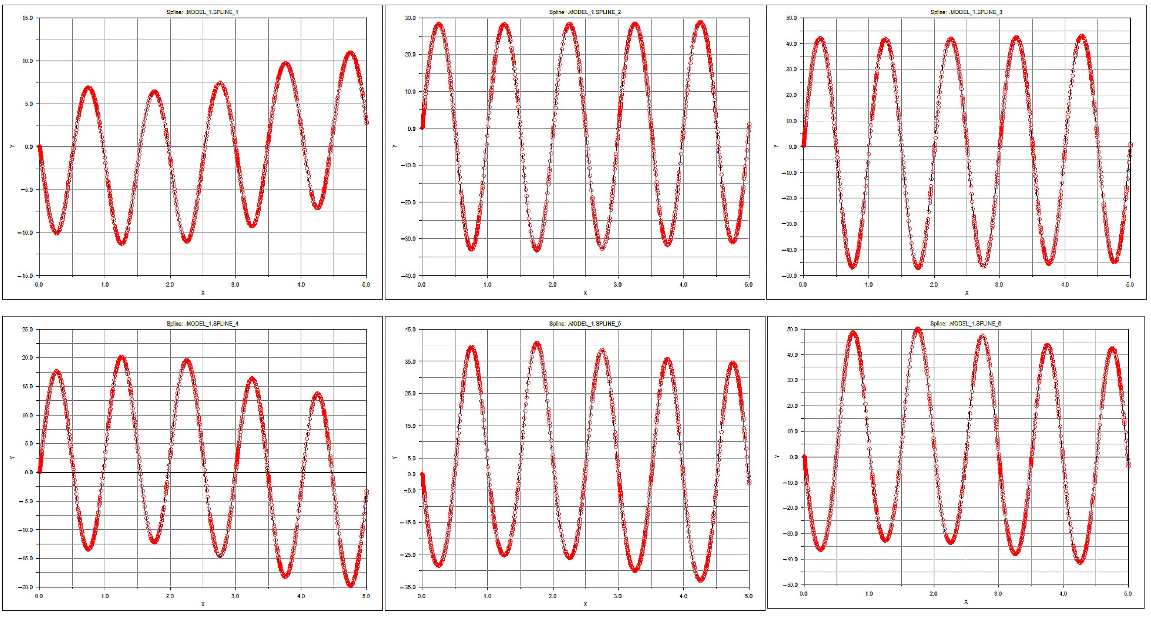
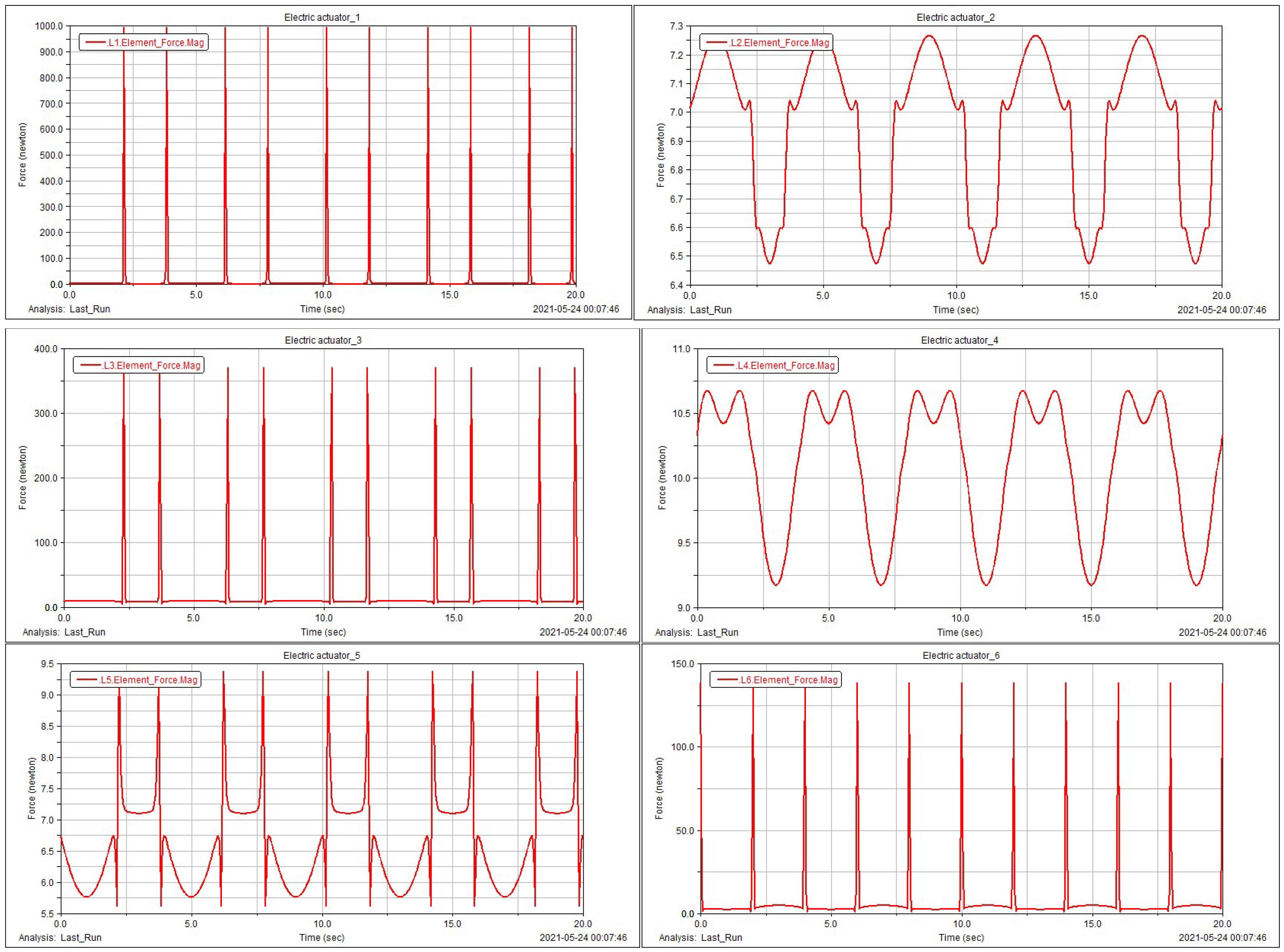
In ADAMS dynamic simulation software (MSC Software Inc., Los Angeles, CA, USA), the forward solution of the platform motion is calculated, and six electric cylinders of the 6-DOF platform are driven to expand and contract, so as to obtain the dynamic position of the platform. Through simulation, the stress curve of the electric cylinder and the stress curve of the lower platform hinge are analyzed, so as to verify the correctness of the inverse solution model. In the dynamic simulation, the upper platform is connected with the electric cylinder by fixed ears and movable ears, the lower platform is connected with the hydraulic cylinder by bearings and supporting ears, and the lower platform is connected with the ground by fixed pairs. For six cylinders, drive functions are added to guide them, and the platform on the model is set with a uniform load of 500 N, and the gravity field is added. The obtained driving curve and stress curve of the electric cylinder are shown in
Figure 9 and
Figure 10, respectively.
As shown in
Figure 9, the abscissa indicates the simulation time, the ordinate indicates the displacement of the electric cylinder, and the red curves are the driving curves of the electric cylinders. The upper and lower graphs of each column correspond to each other, with the same curve shape and symmetrical displacement.
The force curves of the six bearing pedestals are similar in all directions, and there are “double peaks” in the curves, among which the peaks of the electric cylinders 1, 3, 5, and 6 are concentrated, and the force curves of the electric cylinders are continuous, which indicates that there is no phenomenon, such as movement impact in the leveling simulation process. It can be seen from
Figure 9 that the motion of the model is consistent with that of the inverse solution in MATLAB Simulink, and there is no interference; moreover, according to the force curve of each cylinder obtained in
Figure 10, the maximum impact load of 996.53 N in 2.3 s for 1 cylinder, 7.25 N for 2 cylinders at 1.25 s, 375.40 N for 3 cylinders at 2.5 s, 10.63 N for 4 cylinders at 0.9 s, 9.48 N for 5 cylinders at 2.2 s, and 137.55 N for 6 cylinders at 137.55 N. Therefore, the electric cylinder can carry at least 1500 N dynamic load to ensure the normal movement of the platform.
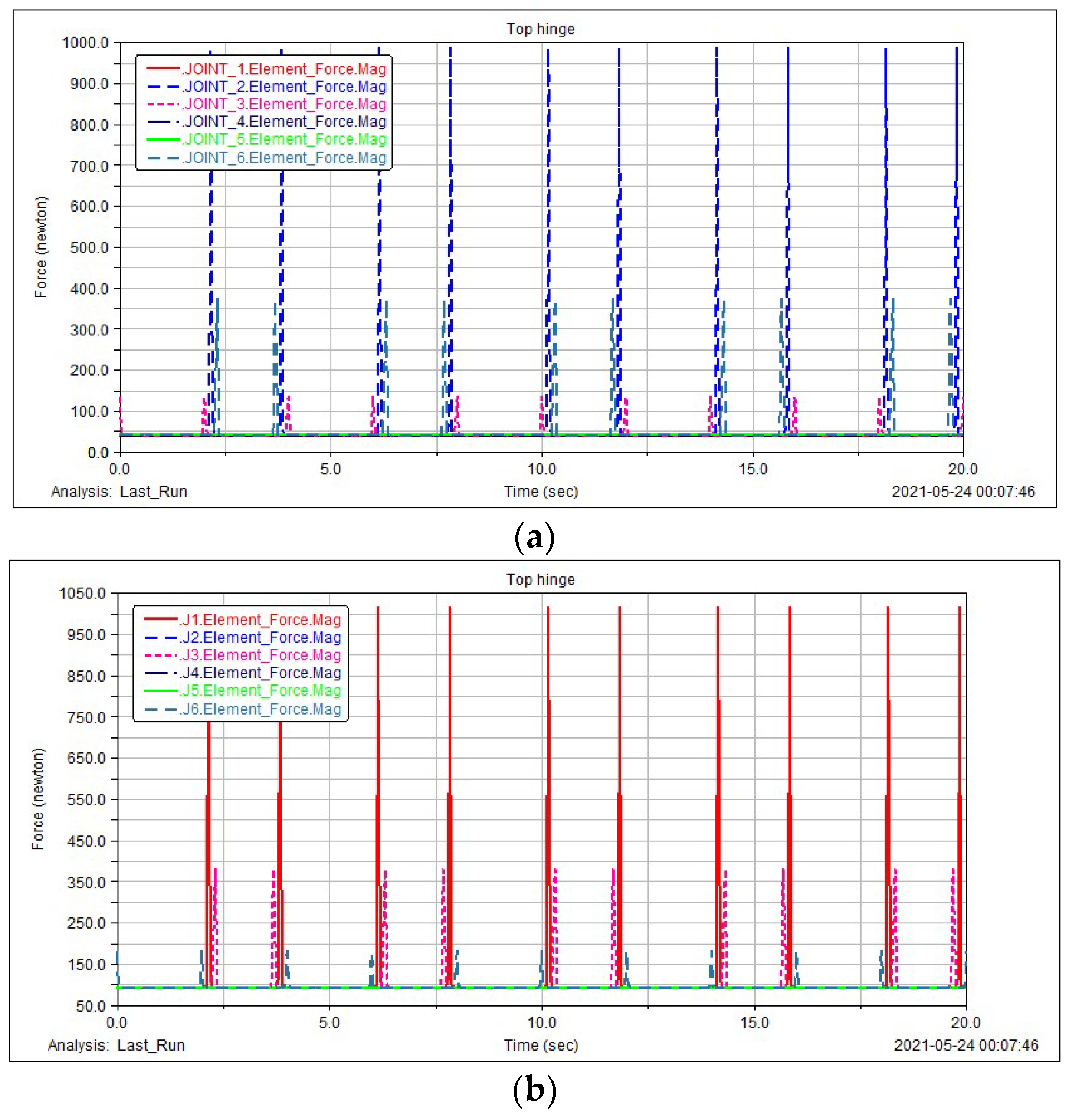
The simulation analysis of the stress on the hinges of the upper and lower platforms is carried out, as shown in
Figure 11.
Figure 11a,b show the stress curves of the upper and lower platforms respectively, obtained by setting a uniform load of 500 N on the upper platform. Comparing the two figures, it can be seen that for upper platform the stress of cylinder 2 and the corresponding hinge is the largest, while for lower platform, the stress of cylinder 1 and the corresponding hinge is the largest. The results show that the hinge of cylinder 2 and the upper platform has the largest stress, with the maximum value of 998.69 N, while the hinge of cylinder 1 and the lower platform has the largest stress, with the maximum value of 1017.75 N. Therefore, when selecting the hinge structure and materials, the stress should be one third of the allowable stress.
Thus, the dynamic simulation goal of the lifting platform is realized.
3. Results
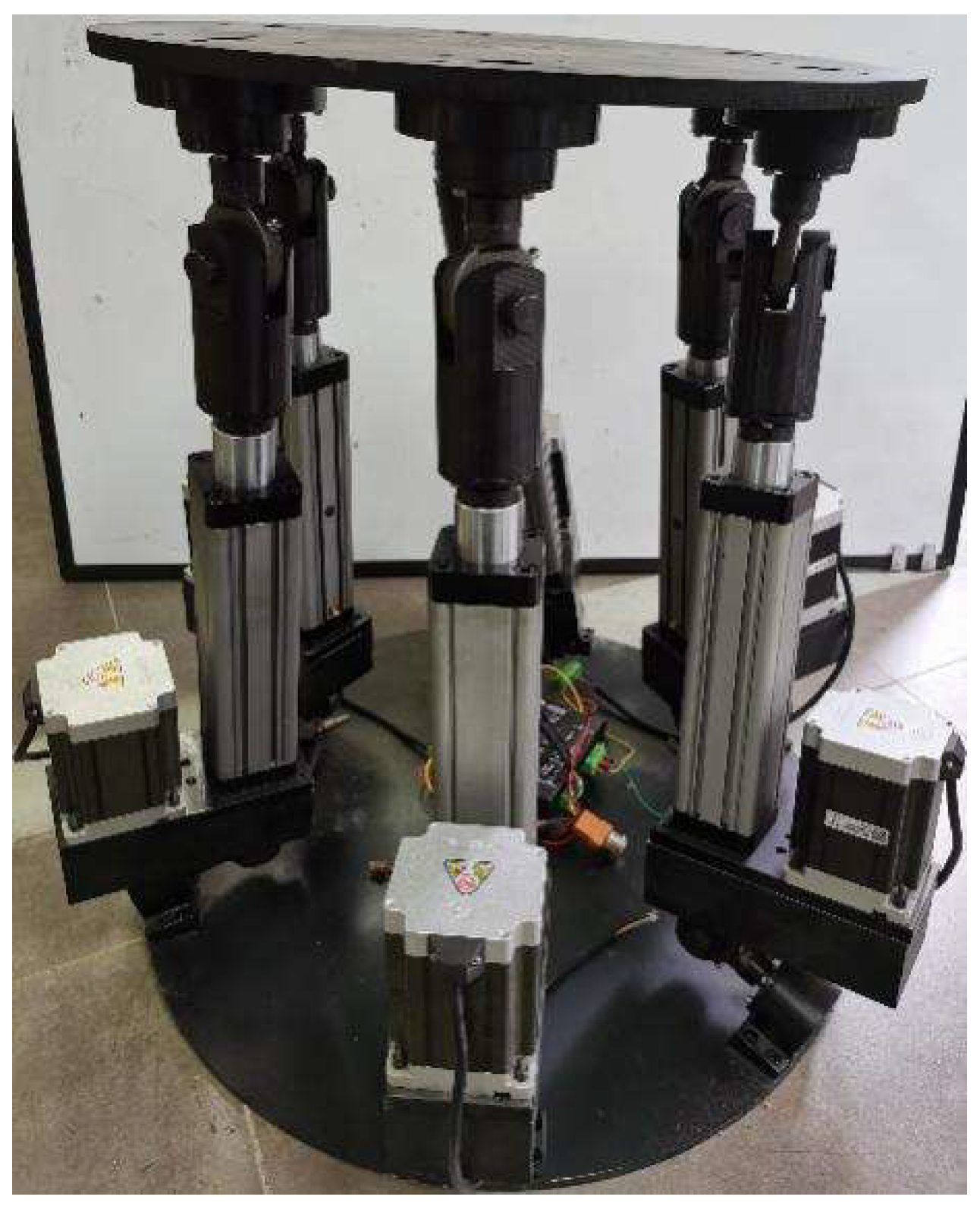
3.1. Physical Construction
In order to verify the feasibility of the above simulation results, the tomato picking lifting platform as shown in
Figure 12 is designed and built according to the parameters of the mechanism.
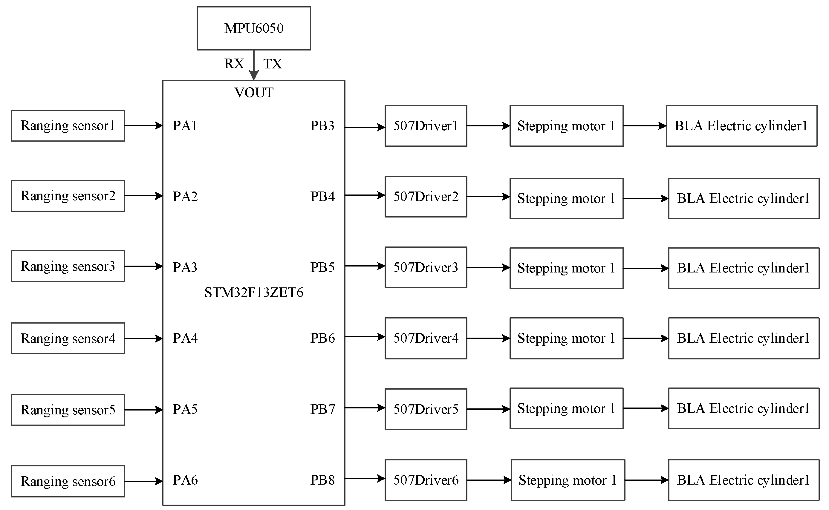
The control system architecture of the lifting platform is shown in
Figure 13, which adopts a folding electric cylinder (Bailile Industrial Automation Co., Ltd., Suzhou, China, BLA-6H-S150-B-T-5-B-M4-C1-400W-J1), a stepping motor (Lei Sai Intelligent Control Co., Ltd., Shenzhen, China, 86CME35) and a pulse universal closed-loop stepping driver (Lei Sai Intelligent Control Co., Ltd., Shenzhen, China). At the same time, a control system is set up to control the motor torque through the number of pulses, so as to control the expansion and contraction of the electric push rod and make the platform reach a stable state. In this paper, the single-chip microcomputer STM32F103ZET6 (STMicroelectronics, Plan-les-Ouates, Switzerland) is selected to write related control programs, and the six-axis sensor chip MPU6050 (InvenSense, San Jose, CA, USA) is selected to monitor and control the three-axis acceleration, angular velocity, and angle. The static accuracy of attitude measurement is 0.05°. In addition, this paper selects the laser ranging sensor (WT53R-TLL) of Weite Intelligent Co., Ltd. (Shenzhen, China) to realize the distance alarm function. The power supply voltage of this sensor is 5 V~36 V, the working current is less than 38 mA, the communication mode is serial TTL, and the update rate is 20 Hz.
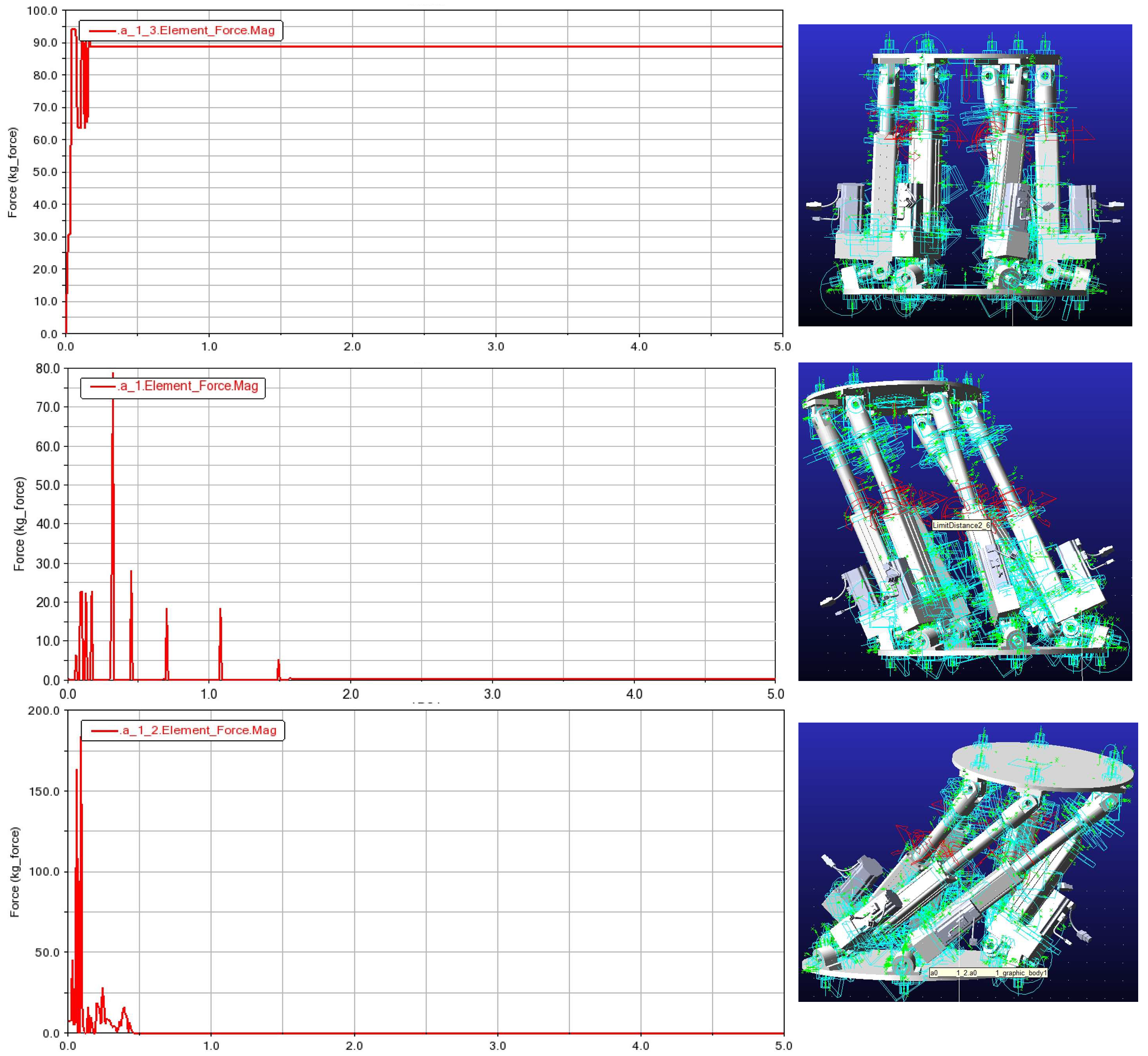
3.2. Whole Machine Motion Simulation after Loading
By adding 50 kg load to the initial position and two extreme positions of the whole machine of the 6-DOF platform and simulating, the stress curve of the hinge point of the lower platform can be derived.
Figure 14 shows the stress curve of the hinge point and the corresponding position of the upper platform.
According to the stress curve, corresponding to each position of the upper platform, the maximum stress on the hinge point of the lower platform is nearly 200 N, which is less than the maximum load that the motor can bear.
The simulation results finally show that the lifting platform can meet the actual load demand.
3.3. Experimental Verification
The lifting height and maximum load of the lifting platform can be easily verified; therefore, this paper mainly designed experiments to detect the angle adjustment accuracy and speed of the lifting platform. We manually inputted the specified angle of the upper platform relative to the
x and
y axes, detected and outputted the inclination value of the platform on the lifting platform in real time through the angle sensor, so that it can automatically reach the equilibrium state, and recorded the time required for the lifting platform to reach the specified angle. Test data are shown in
Table 1.
The experimental data show that the average time for the system to reach steady state is 0.309 s, and the in-tilt error increases with the increase in biaxial tilt angle, with the maximum error of 1.09° and the maximum mean square root error of 0.119°. When the inclination angle of one axis increases and the inclination angle of the other axis remains unchanged, the error of balance will also increase, which is mainly due to the coupling problem of the inclination angles of two axes. In addition, the test data also show that the error of the angle response of the model test platform is within the standard range, and it can accomplish the lifting and leveling functions well. The maximum rotation angle of the platform around the x, y, and z axes is 10°, the maximum lifting distance is 15 cm, and the maximum load is 50 kg, which can meet the automatic operation requirements of the tomato picking manipulator.
4. Discussion
In this paper, a motion platform is designed, which has the functions of automatic lifting and leveling, and can accurately stop at the specified height to complete the picking operation. Firstly, the environment of tomato planting and picking operation was analyzed, and then the kinematics inverse solution was carried out to determine the basic parameters of the platform. Secondly, SolidWorks software was used to build the three-dimensional model of the platform, and Simulink was used to build the simulation model. The inverse solution was used to obtain the telescopic curve of the electric cylinder and determine the stroke of the electric cylinder. Then, ADAMS was used to build the virtual prototype of the lifting platform, the dynamic simulation of the electric cylinder was completed by using the driving function, and the stress curves of the electric cylinder and the hinges of the upper and lower platforms were obtained. Finally, the physical construction and experimental verification of the picking lifting platform were completed. The results show that the maximum rotation angle around the x, y, and z axis is ± 10°, the maximum lifting distance is 15 cm, and the maximum load is 50 kg; meanwhile, the average time for the system to reach steady state is 0.309 s, the in-tilt error increases with the increase in biaxial tilt angle, with the maximum error of 1.09° and the maximum mean square root error of 0.119°, which can meet the automatic operation requirements of the tomato picking manipulator.
It should be noted that the purpose of this design is to cooperate with the greenhouse tomato picking robot. Therefore, compared with the requirements of traditional picking lifting platforms that focus on lifting range, load size, and running stability, this design emphasizes the accuracy and rapidity of platform motion posture. In addition, the main purpose of the design of the picking lifting platform in this paper is to optimize the working space of the mechanical arm, so that it can reduce the design difficulty and structural complexity of the mechanical arm, decrease the volume and inertia of the mechanical arm, and, thus, improve the performance price ratio of the mechanical arm while moving quickly to the best working position. Briefly, the picking lifting platform designed in this paper is mainly aimed at specific working conditions, and needs to be used with a moving chassis of certain size and load capacity, which is the limitation of this design.
In the follow-up research, the research will be devoted to the cooperative control of the tomato picking manipulator, lifting platform, and chassis, to verify what extent the platform can improve the performance of greenhouse tomato picking, and propose further optimization design schemes. At the same time, other lifting platforms with wider applicability will be developed to reduce the overall design difficulty and structural complexity of the picking robot, so that it can be popularized and applied to other fields of agricultural automatic production operations.


