Article

Adapting Neural-Based Models for Position Error Compensation in Robotic Catheter Systems

1
Research Center for Medical Robotics and MIS Devices, Shenzhen Institutes of Advanced Technology, Chinese Academy of Sciences, Shenzhen 518055, China
2
University of Chinese Academy of Sciences, Beijing 100049, China
3
Shenzhen College of Advanced Technology, University of Chinese Academy of Sciences, Shenzhen 518055, China
4
CAS Key Laboratory for Health Informatics, Shenzhen Institutes of Advanced Technology, Chinese Academy of Sciences, Shenzhen 518055, China
*
Authors to whom correspondence should be addressed.
Appl. Sci. 2022, 12(21), 10936; https://doi.org/10.3390/app122110936
Submission received: 22 September 2022 / Revised: 23 October 2022 / Accepted: 25 October 2022 / Published: 28 October 2022
(This article belongs to the Topic Designs and Drive Control of Electromechanical Machines)

Abstract

:

Featured Application

Robot-assisted surgery has simplified minimally invasive treatments by providing surgeons with more enhanced skill, precision, and control of surgical instruments for microscale operations than is possible with conventional methods. A use case is robot-assisted percutaneous coronary intervention, which utilizes a robotic catheter system to remove lesions in the coronary arteries. Typically, the RCS provides discrete, repetitive, and steady motion to endovascular tools for tooltip translation from an insertion site to the blocked coronary arteries while ensuring vessel damage avoidance. Therefore, this study aims to enhance master–slave motion accuracy toward the realization of autonomous navigation during robot-assisted cardiac interventions.

Abstract

Robotic catheter systems with master–slave designs are employed for teleoperated navigation of flexible endovascular tools for treating calcified lesions. Despite improved tool manipulation techniques, patient safety and lowering operative risks remain top priorities. Therefore, minimizing undesirable drifts and imprecise navigation of flexible tools during intravascular catheterization is essential. In the current master–slave designs, finite displacement lag between position command and actual navigation action at the slave device affects smooth catheterization. In this study, we designed and developed a compact 2-DOF robotic catheter system and characterized the influence of displacement step values, velocity, and motion gap on the position error at the slave device. For uniform and varying motion commands from the master platform, the results indicate that the overall position error increases with the distance traveled and the displacement step values, respectively. Hence, we proposed using recurrent neural networks—long short-term memory and gated recurrent unit controllers to predict the slave robot’s position and appropriate compensation value per translation step. An analysis of in-silico studies with CoppeliaSim showed that the neural-based controllers can ensure uniform motion mapping between the master–slave devices. Furthermore, we implemented the models within the RCS for a catheterization length of 120 mm. The result demonstrates that the controllers suitably aid the slave robot’s stepwise displacement. Thus, the neural-based controllers help match the translational motion and precise tool navigation by the slave robotic device. Therefore, the neural-based controllers could contribute to alleviating patients’ safety concerns during robotic interventions.

1. Introduction

Vascular diseases, such as aneurysms and stenosis, adversely affect blood flow to vital organs and other body tissues. This condition has been categorized as atherosclerosis when it affects the coronary, carotid, or peripheral arteries [1]. As a systemic and inflammatory vascular process, atherosclerosis causes plaque aggregation within the arterial lumen. The presence of atherosclerotic lesions in the coronary arteries, referred to as coronary artery disease (CAD), interrupts the flow of oxygen-rich blood to the heart muscle, thereby eliciting symptoms such as numbness, angina, and myocardial infarction [2]. As a result, CAD is a significant cause of global disease burden and accounts for over 80% of sudden cardiac deaths [3]. Conventionally, interventionalists require large incisions into the chest cavity for procedures such as graft bypass around clogged arteries to reroute blood flow to the heart. However, percutaneous coronary intervention (PCI) has been widely adopted for the diagnosis and treatment of CAD as it offers patients reduced perioperative morbidities and faster recovery times [4,5,6,7].
In PCI procedures, intravascular catheterization is a vital step in which patients’ vessels are cannulated with thin and flexible endovascular tools, viz. guidewire, catheter, and rapid exchange devices. This routine procedure involves tool navigation from an entry port, typically on the radial, femoral, or brachial vessels, to noticeable lesions in the coronary arteries. Intravascular catheterization is performed with trained interventionalists applying fine motor skills [7,8]. This includes axial operations such as translational (push/pull) and rotational movements applied proximally, while the movement transmits distally to navigate endovascular tools within the patient’s vasculature. However, precise manipulation of endovascular tools in a dynamic cardiac environment such as a beating heart and fragile vessels persists as a challenge in cath labs. Hence, interventionalists undergo extensive training and evaluation sessions for safe tool manipulation during PCI. Unfortunately, this limits the availability of operators with certified proficiency for manual catheterization relative to the recent high global prevalence rate of vascular diseases such as CAD [8,9,10,11].
Robotic catheter systems (RCSs) have been introduced into cath labs to reduce PCI operational risks such as radiation exposure hazards and orthopedic injuries to interventionalists. Robotic-assisted PCI (R-PCI) is performed with the RCS having a unique master and slave platform to ensure the surgeons’ safety while offering remote tool manipulation [12]. Globally, CorPath® 200 and CorPath® GRX (Siemens Healthineers, Walpole, MA, USA) are FDA-approved commercial products developed to facilitate precise navigation of flexible endovascular tools with enhanced dexterity and a reduced learning curve for R-PCIs [13,14]. In addition, CorPath® GRX offers higher functionalities such as guided control and improved device exchanges. However, to achieve smooth motion during procedures, the CorPath systems translate endovascular tools with a displacement step of 1 mm or a maximum speed of 12 mm/s. Hence, its motion accuracy for higher displacement step values is unsubstantiated [15]. Despite the evidence supporting the safety and feasibility of RCSs for R-PCIs, they are currently available in only a few hospitals globally. Furthermore, it is projected that RCSs with higher autonomy can aid better patient outcomes, and thus it is deemed an area requiring further research for technological improvements [16,17].
RCS prototypes with master–slave position-tracking capabilities for safe and responsive tool navigation at different displacement step values were developed in several studies. For instance, Al-Ahmad et al. [18] proposed a catheter drive system with sleeve-based grippers using pneumatic actuation. The clamping strategy ensures an equivalent force distribution along the catheter while providing continuous motion. However, further validation of the catheter driver is required. Similarly, in [19], the authors integrated the master–slave components into a singular unit. The slave platform replicates an operator’s action on the master handle via a linear actuator, while a clutch mechanism allows the device to reposition the master unit for continuous catheter motion. Nevertheless, single-unit systems impede remote operation, which requires a distinct master and slave unit.
Furthermore, Cha et al. [20] developed a master–slave robotic platform with two degrees of freedom (2-DOF) for catheter and guidewire continuous motion during R-PCI. However, the system utilized a user-defined scaling factor to achieve master–slave position accuracy during procedures. Likewise, the researchers in ref. [21] evaluated the design of a 2-DOF RCS system for teleoperated catheter navigation. The tool manipulator relies on a linear drive mechanism and a slip ring framework to translate and rotate the catheter within a vascular phantom by reproducing the operator’s axial and radial motion at the master unit. Nonetheless, the system required a constant scaling factor for master–slave position mapping. Motion scaling is a complementary motion control strategy used in telerobotics. However, it holds better potential in teleoperated systems with high network latency, such as the Da Vinci robot [22]. The endovascular RCS developed by Sankaran et al. [23] endeavors to replicate the interventionalist’s natural dexterity, requiring a minimal learning curve. The master unit has a quick-release mechanism with friction wheels to advance or retract the catheter or guidewire. The RCS utilized an adaptive input shaper and the proportional-integral-derivative (PID) controller for position control at the master–slave ends. Overall, these existing studies utilized motion scaling or conventional controllers to track the accuracy of master–slave positions during robot-assisted procedures. Nevertheless, tuning conventional controllers could be simplistic and imprecise resulting in a loss of performance. However, to enhance operational safety during robotic interventions, some other studies have developed different approaches, such as position control [24,25,26], motion scaling or compensation [20,21,27,28], and force feedback [29,30]. Nonetheless, there is limited proof of their stability and robustness for position control tasks that involve flexible endovascular tools. Furthermore, manufacturing constraints and miniature size requirements complicate the integration of force sensors at the tool’s tip.
The choice of the slave robot’s drive mechanism and motion control strategy is an essential criterion for safe tool navigation during R-PCI. As shown in Figure 1, the conventional drive mechanisms include (1) ball screws, a belt drive, and roller screws and (2) clamping and translation mechanisms, while magnetic actuation helps to manipulate a robotic catheter’s tip. For instance, gripping or ball screw actuation provides the necessary thrust for the catheter’s translational motion. However, these actuation designs subject the endovascular tools and RCS to backlash and hysteresis, motion nonlinearities, and uncertain disturbances. These are due to frictions, inertial forces, or temporal interruptions when restoring the master’s device to its starting position during translation operations. While backlash in endovascular tool motion has been addressed [27,31,32], nonlinearity in RCSs is yet to receive any attention. The latter causes control complexities, such as motion lags in slave robots during catheterization [27]. Hence, existing systems operate at lower displacement step values.
Modeling the slave robot’s motion dynamics to characterize uncertain disturbances, e.g., hysteresis in the under-actuated RCS, is challenging and imprecise [34]. In addition, this could be a vital underlying factor hindering robot autonomy in R-PCIs. In response to the complexity of modeling surgical robots, data-driven approaches based on the black box model have become increasingly popular. Omisore et al. [32] employed a nonlinear autoregressive neural network to estimate the hysteresis effect on a uni-directional coronary catheter using its kinematic parameters. The researchers in ref. [35] utilized the long short-term memory network (LSTM) to model the hysteresis of a uni-directional robotic catheter and to predict its pose. Cursi et al. [36] used a feed-forward neural network to model the kinematics of a tendon-driven surgical tool and to compensate for the motor’s backlash. However, these approaches apply to steerable catheters or continuum robots [35,36]. In R-PCI, the standard coronary catheter is a non-steerable flexible tool without links or joints. Similarly, RCSs are mainly under-actuated, and physics-based modeling serves little benefit for position control. Furthermore, the existing studies have not utilized a data-driven approach to compensate for position error in such under-actuated RCSs.
This study aims to improve master–slave position tracking capabilities using a recurrent neural network, implemented and evaluated for real-time prediction and error compensation in a slave robot during catheterization. We hypothesized that a learning-based control system would help to optimize the slave robot’s precision and response to motion commands received from the master platform. Thus, the catheter drive mechanism could navigate the flexible endovascular tools with higher precision and better minimize position errors that may arise from unknown disturbances and nonlinearities during catheterization. We characterized position errors using a set of actuation commands in a self-developed RCS and trained two recurrent neural network models to learn master–slave motion mapping and to predict the slave robot position for given input variables. Therefore, we evaluated the feasibility and performance of the LSTM and gated recurrent unit (GRU) based controllers. The main contributions of this study are:
(1)
The design and development of a custom 2-DOF RCS for endovascular navigation with specification analysis of its main components.
(2)
The experimental characterization of the slave robot’s responses to uniform and varying motion commands.
(3)
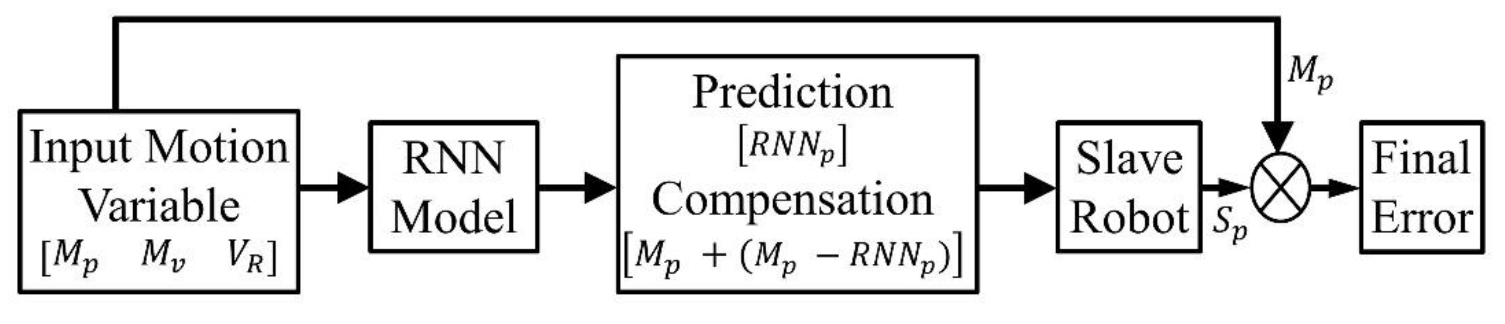
An open-loop control model with validation of the neural-based controllers for position prediction and error compensation in the slave robot using in-silico and in-RCS experiments.
The remainder of the paper follows an outline where we present the design of the custom RCS in Section 2, while the characterization of the axial translational position error and the backlash gap within the RCS is presented in Section 3. In addition, we present the neural-based model proposed for the prediction of the slave robot position in Section 4. Furthermore, we highlight the performance analysis of the models based on in-silico and in-RCS analyses in Section 5. Finally, Section 6 highlights the discussion, conclusions, and future work.

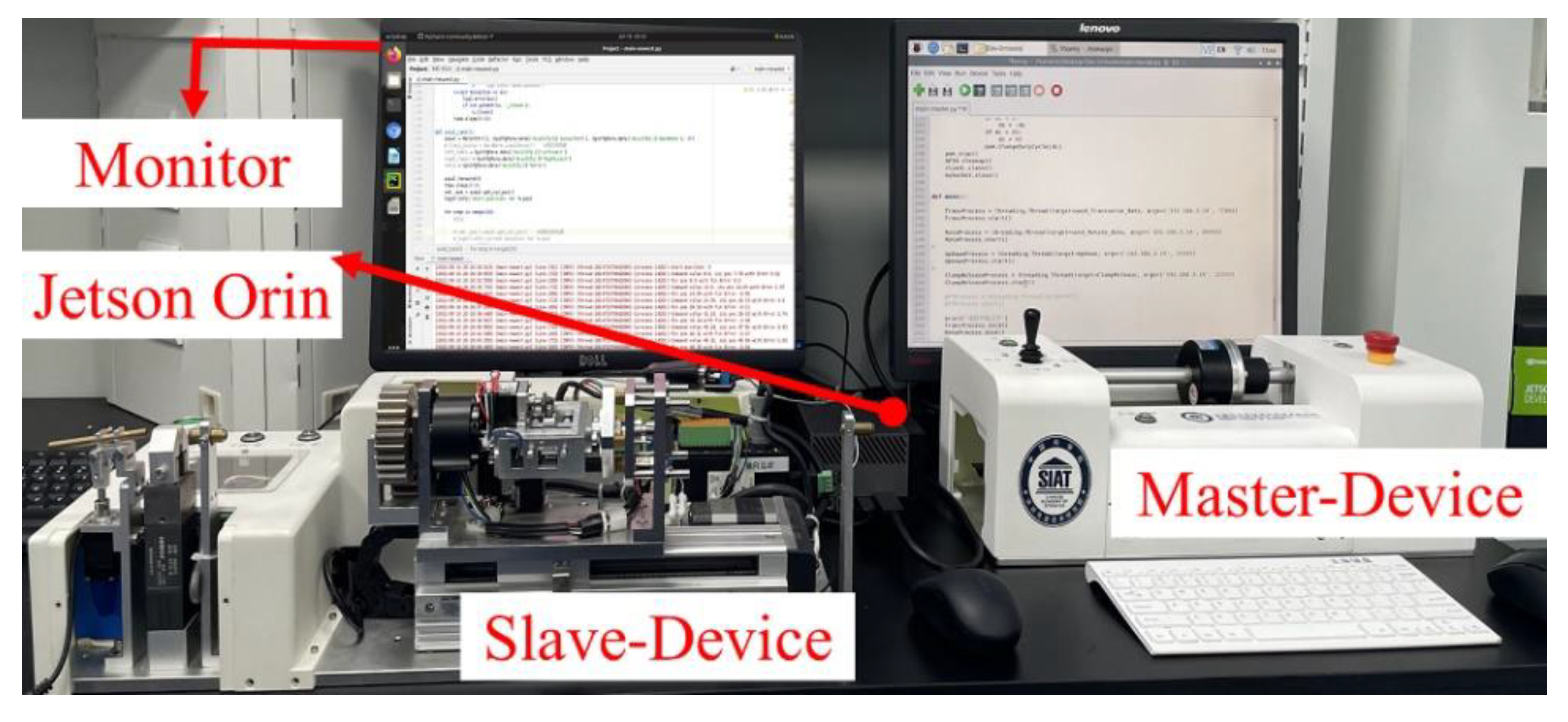
2. Design of the Robotic Catheter System

We present the functional design of the RCS and its main components in this section. The teleoperated system comprises a master and slave platform for endovascular tool remote manipulation during R-PCIs. The master–slave platform has dimensions of 45 cm × 19 cm × 13 cm in length, width, and height, and weighs 15.5 Kg and 26.0 Kg, respectively. It is worth mentioning that the current prototype is an improvement on our previous versions [12,26,27]. Furthermore, the designed mechanism ensures that the interventionalist requires a minimal learning curve to operate the RCS for intraluminal navigation. We present an outline of the detailed description of the master–slave platform below.

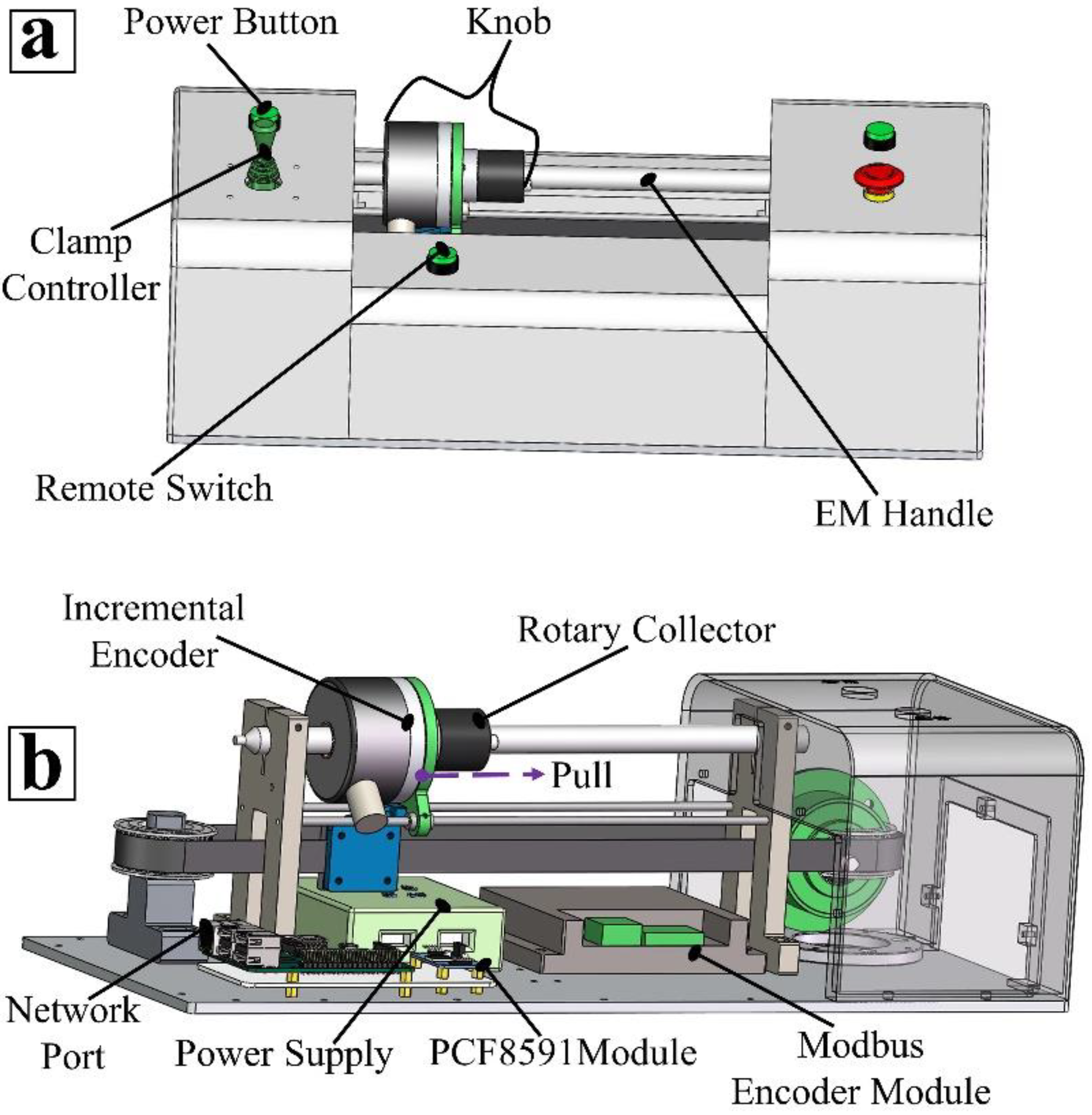
2.1. Design of the Master Robotic Device

By encoding the operator’s natural hand movements, the master device (Figure 2) communicates appropriate signals to the slave platform (typically at the patient’s bedside) to perform the axial translation and radial movement of flexible tools during R-PCI. The bi-axial DOF design consists of an incremental encoder, rotary collector, encoder module, etc., as shown in Figure 2a,b. Incremental encoders provide excellent feedback regarding speed and distance by generating pulses corresponding to their axial displacement across the electromagnetic handle. The signals are transmitted to the encoder module, where they are aggregated, and the corresponding position command is sent to the slave robot platform. This includes forward commands that drive the slave robot to advance an endovascular tool and pull movements for tool retraction during procedures. Similarly, the encoder (EKT58 series, JADE Optoelectronic Company, Wuxi, China) has a resolution of 5000 cycles per revolution (CPR) and a measurement frequency of 100 KHz. It generates corresponding pulses from clockwise or anticlockwise twists of the rotary collector by an operator, which are converted into discrete angular values to enable precise rotational movement of an endovascular tool by the slave robot.
In addition, the master device allows for simultaneous translational and rotational movements. Typically, this movement includes rotating on advance or retract operations generated by turning the rotary collector after moving the encoder along the handle or vice versa. This unique movement has been proven as a way interventionalists skillfully navigate guidewire or catheters through complex paths within the heart coronaries [14]. Furthermore, the clamp controller coordinates the slave’s tool-grasping fixtures to maintain a fixed pose of the flexible tool, thus preventing tool slippage and potential risks from blood vessel puncture during procedures. The stroke length of the master device is 120 mm. However, to achieve an infinite translational motion, the remote switch (Figure 2a) triggers after a full stroke for either forward or backward drive of the cylindrical knob towards the starting position without corresponding movement at the slave side. On the other hand, when the remote switch turns off, a displacement of the cylindrical knob advances or retracts the tool further at the slave side. Hence, the realization of an infinite motion for a given intravascular procedure. The encoded motion information at the master side is transmitted to the slave device via a wireless network using a transmission control protocol/internet protocol (TCP/IP) address. Additionally, a 12-volt DC-powered rechargeable lithium-ion battery, as shown in Figure 2b, is used to power the master device. At the same time, a DC boost module ensures the realization of varying step-up and step-down voltage-to-current during a given procedure, thus offering high efficiency across input and output voltage ranges.

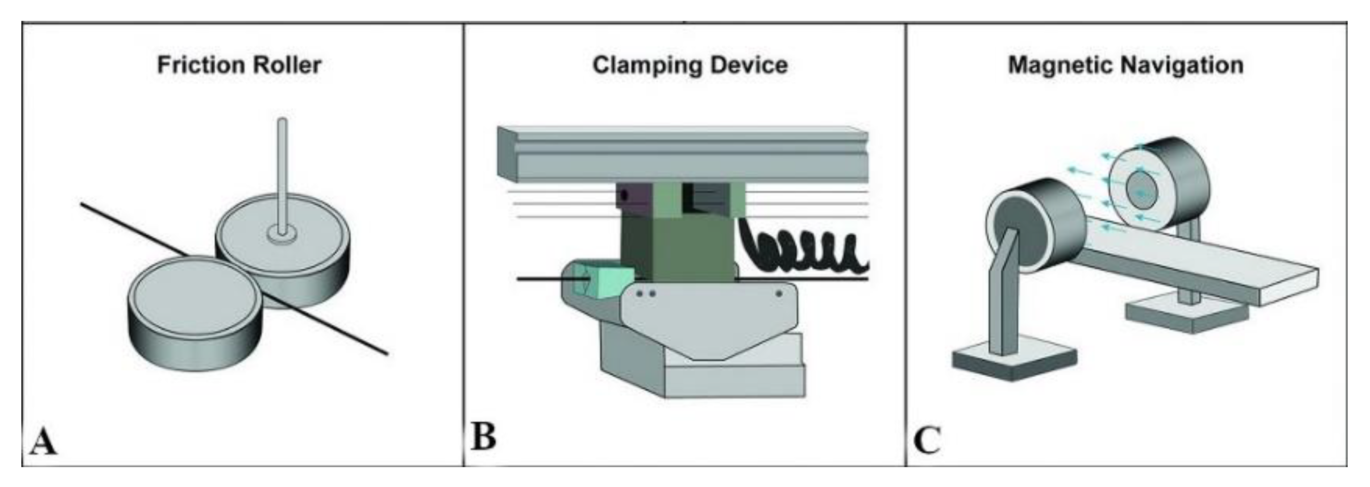
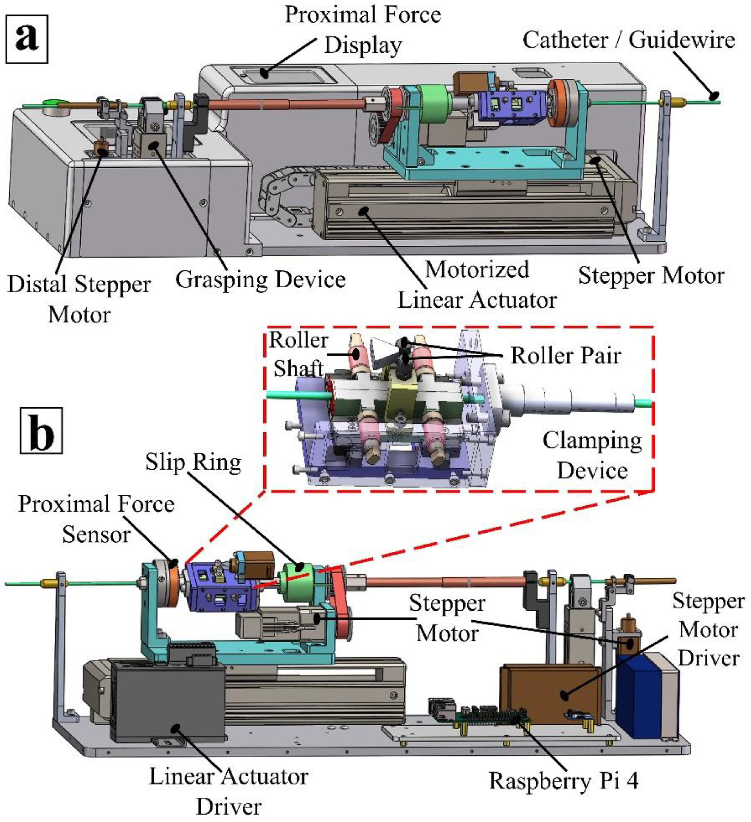
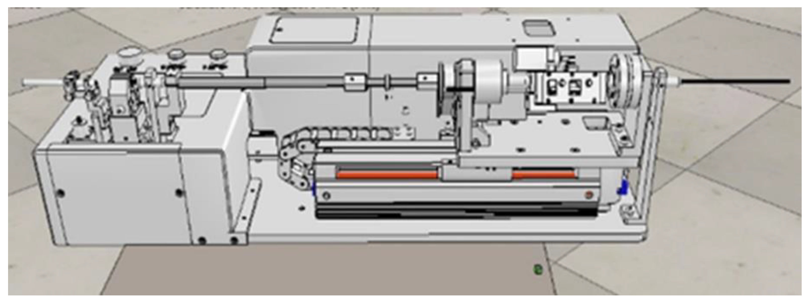
2.2. Design of the Slave Robotic Device

As shown in Figure 3a,b, the slave-side robotic device comprises a 2-DOF mechanism geared by stepper motors and a linear actuator. The slave platform implements the actual navigation of the endovascular tool based on input commands received from the master unit.
For this custom setup, the slave platform utilizes a motorized linear actuator (EAS4RXE015, Oriental motor, Tokyo, Japan) with a width and height of 58.4 mm × 60 mm, a stroke length of 150 mm (accuracy: ±0.02 mm), and a resolution of 5000 CPR, as shown in Figure 3a. The actuator employs a ball screw mechanism for its axial drive and is powered by a DC-input stepper motor (AZM24AK, Oriental motor, Tokyo, Japan), resolution: 1000 CPR, a motor driver (SR series, MOONS’, Shanghai, China), and a linear actuator driver (AZD-KD, Oriental motor, Tokyo, Japan), as shown in Figure 3b. In addition, two limit sensors placed 15 mm from both ends of the linear actuator prevent the sliding plate from going beyond the terminal ends of the axial stage. Thus, one-to-one position mapping exists between the master–slave devices, with an active stroke length of 120 mm. The sliding plate houses the proximal force sensor, slip ring, and clamping mechanism. A rotary stepper motor attached to the sliding plate drives the belt and pulley system for rotational movement of the endovascular tool as controlled by the master.
In addition, as shown in Figure 3b, a miniature linear stepper motor (8k2105, SAMSR motor, Shenzhen Melike Technology Co., Ltd., Shenzhen, China) positioned above the clamping device turns a roller pair, controlling the opening and closing of the clamp via a lateral shift of the clamping controller at the master side. When opened, an operator manually steers the guidewire or catheter through the clamp, the guide sheath, and the grasping device to position the flexible tool at the entrance of a peripheral access port, from where the master–slave device operates the endovascular tool for intravascular the catheterization procedure. The clamp achieves a fixed grasp of the endovascular tool during axial and rotary motion when held in a locked position via four smaller roller shafts, as shown in Figure 3b. The clamping force between the device and the tool, as measured by the proximal sensor (KD24s, ME-Meßsysteme GmbH, Hennigsdorf, Germany) with a resolution of 0.002 N and a range of 2 N, is fed back to the operator during procedures. Input-to-output motion and imaging feedback during procedures could aid the development of state-based navigation in RCSs using learning-based models [10,37].
Furthermore, as shown in Figure 3, the distally positioned stepper motor facilitates adjustment of the guide sheath angle to optimize the tool’s navigation during catheterization procedures. A DC 24V 10,000-mAh rechargeable lithium-ion battery powers the slave device for a mean of 270 min, while a Raspberry PI 4 (Raspberry Pi Foundation, South Cambridgeshire, UK) single-board computer with 8 GB RAM is used for data processing and transfer between master and slave devices.

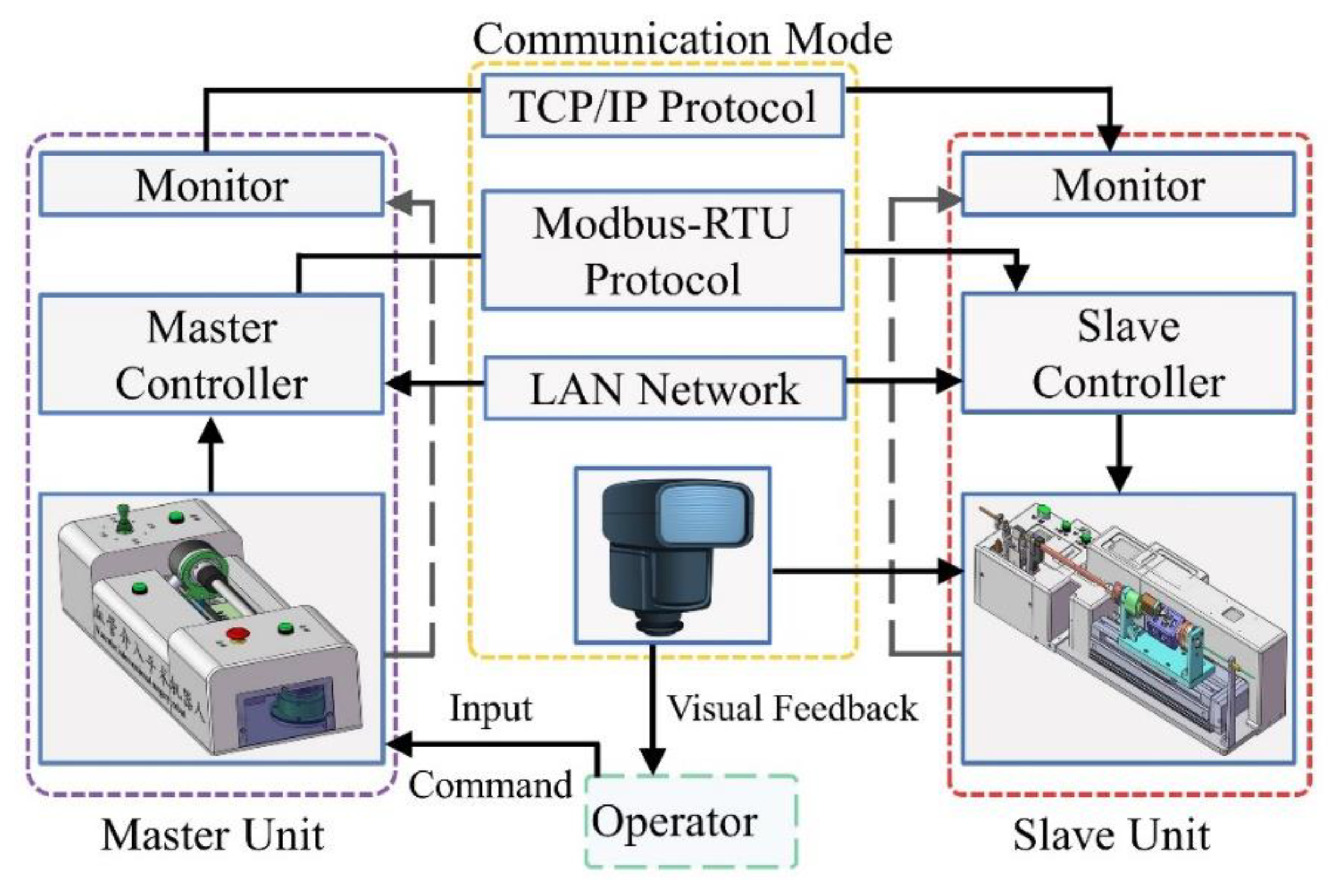
2.3. Communication Modality

The master–slave platform facilitates data exchange via an open-source communication protocol from Modbus (Schneider Automation Inc., Rueil-Malmaison, France) and a wireless network protocol as shown in Figure 4. The RCS intercommunicates through the Modbus remote terminal unit, based on the RS485 standard, with a controller area network (CAN) and expansion board that allows transmitting/receiving data between Raspberry PI and other devices via RS485/CAN functions. Typically, the slave robot executes a given action and performs an error check before feedback of the completed action to the master device for subsequent commands. An 8-bit analog-to-digital (A/D) and digital-analog (D/A) converter chip, PCF8591 module (NXP Semiconductors, Eindhoven, Netherlands), aids A/D–D/A sampling in Raspberry PI via an inter-integrated circuit communication interface. Both linear and rotary data are intra-processed by the system module within the master–slave Raspberry PI and transmitted to the corresponding motor drivers, which actuate the linear or rotary motors for an axial or rotary drive of the catheter/guidewire.
The interventionalist relies on sensory feedback such as visual feedback and inter-communication between the master–slave devices for precise tool navigation. The system employs an onboard control system wherein the slave device receives control actions via preprogrammed instructions in a Raspberry PI operating system and thus could perform routine tool movements with discrete motion commands.

3. Characterization of Position-Tracking Error in Robotic Catheter Systems

Smooth and safe tool manipulation requires developing a precise position-tracking ability in the RCS presented above. Position tracking involves iterative geometric mapping between the axial commands (viz. linear or angular displacement) issued via the master device and the actual response from the slave device. This suitably helps to maintain steady translation and rotation movements between the master and slave platforms for robot-assisted catheterization. First, we characterized the RCS parts to establish the presence of motion lag or backlash gaps between the master and slave platforms. Existing studies hypothesized sources of motion lags in RCSs to be from actuated gears, belts, and pulley configurations in linear systems and that become evident during axial translations [21,37]. Practically, this could cause nonlinear but observable marked differences between the motion applied at the master device and the actual cannulation achieved with the slave side. Although new technologies in linear drive systems seek to produce low-backlash devices, none can eliminate the occurrence of position error when using the master–slave setup for R-PCI.
To characterize this situation in our RCS, we performed several experiments to observe the tracking errors between the master–slave platforms. This includes navigation trials performed with varying conditions, i.e., by issuing different position values at the master side and other trials under constant displacement. In all trials, higher-order motion data were derived from the position and velocity outputs from the in-built encoders’ readings.

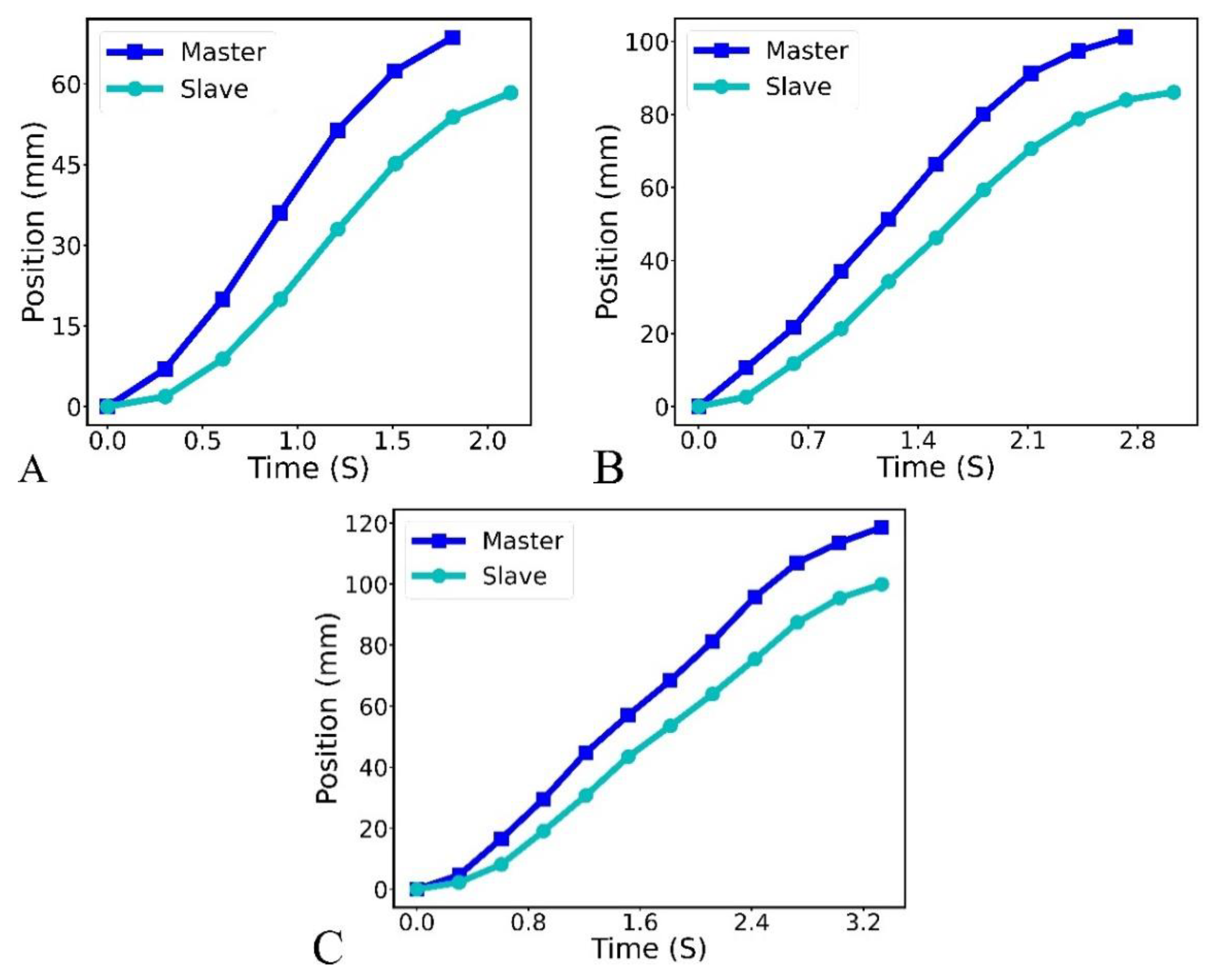
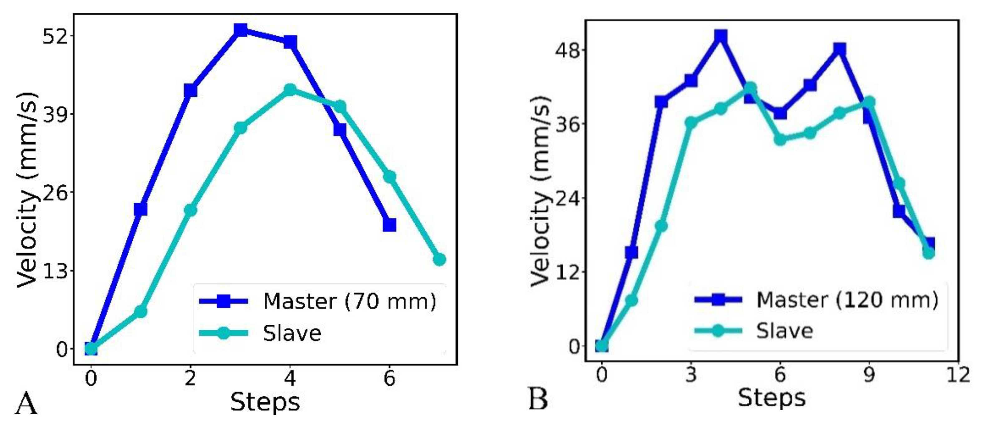
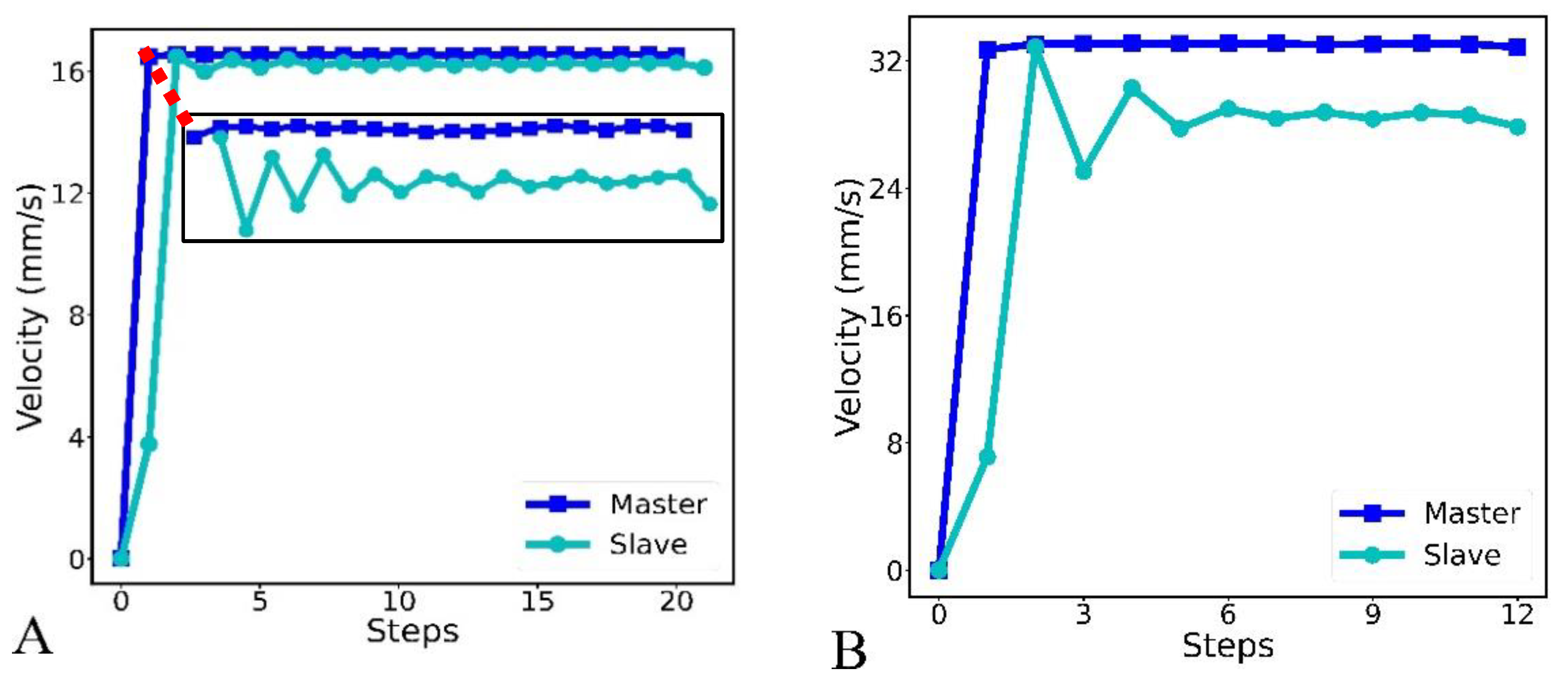
3.1. Experimental Observation of the Master–Slave Position and Velocity Based on an Operator Hand Motion

To quantify the occurrence of position-tracking errors during axial translations with our custom RCS, we segmented the master’s stroke into several discrete points to have the RCS navigate a well-controlled path length each time. An operator was made to navigate the master through 30, 45, 70, 100, and 120 mm lengths. Each navigation trial was performed five times, and the average displacement data were recorded for the navigation length. In this procedure, the operator randomly moved the cylindrical knob in the master device from a starting position to each discrete point. This triggers the slave robot to translate along the linear path. Ideally, the master–slave positions should align from the start to the end of a given translational motion with an equal magnitude of distance traveled at both ends. However, we observed that distinct position errors existed in the trials. From the statistical analysis outlined in Table 1, the mean and standard deviation of the slave device’s position error for each discrete point indicate that the tracking error increases as the length of the path navigated increases. Similarly, based on the operator’s hand motion, the average resultant errors (ARE) for 70 and 120 mm were 10.26 and 18.61 mm, respectively, as shown in Figure 5A,C, while the percentage resultant error (ARE/distance) varied from 14.6 to 19.9%.
The mean velocity of the master–slave devices obtained when distances of 70 and 120 mm were navigated are shown in Figure 6A,B. The interval between the master–slave velocities was greater in Figure 6A. Relating this to Figure 5A, it indicates that the motion gap increases with the velocity gap in the master–slave platforms for varying translational motion but not necessarily with the catheterization distance. Thus, this elucidates why Figure 5A (70 mm) has a more significant motion gap than Figure 5C (120 mm). In addition, the magnitude of the interval between consecutive points during a catheterization stroke is proportional to the motion gap experienced by the slave robot. Again, we have observed that for a shorter distance (30–70 mm), a novice operator is more likely to move the master knob faster (and at a higher velocity) than for a longer distance (100–120 mm). This could be why fewer motion gaps occurred between the master and slave trajectories when longer distances were moved. Nonetheless, we found that the magnitude of the resultant position error increases with catheterization length.

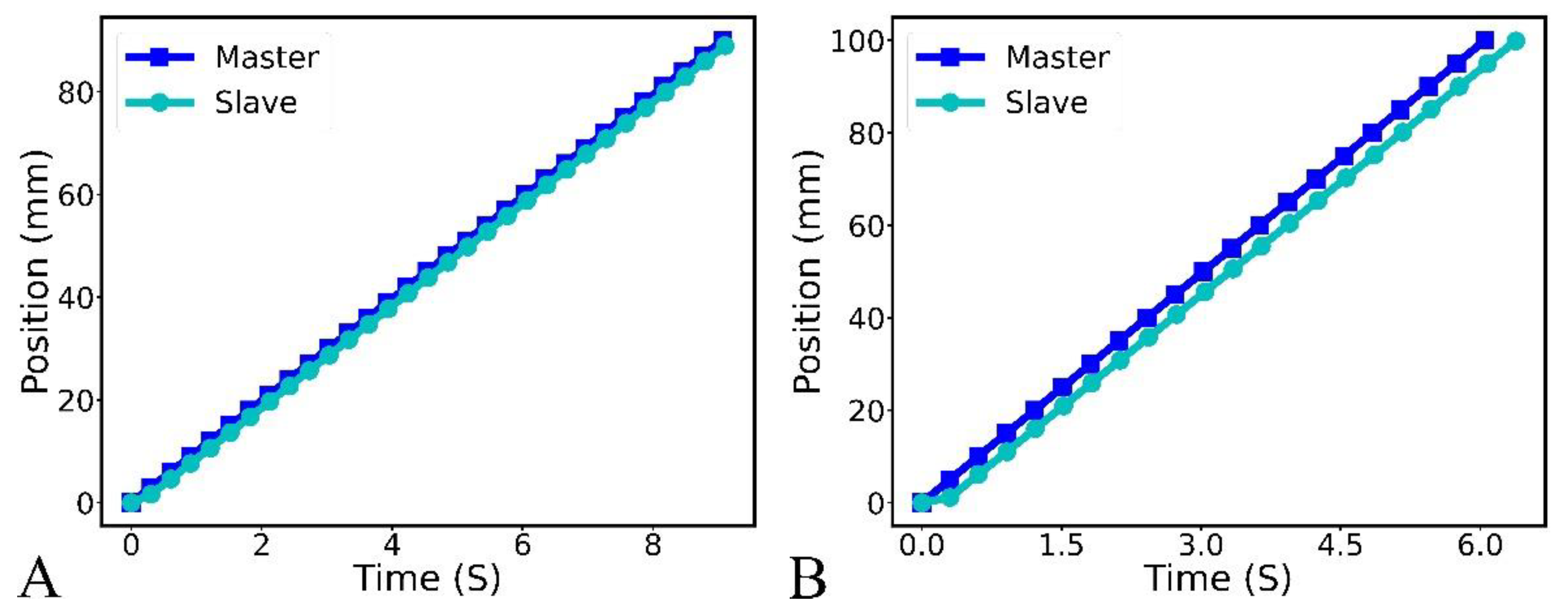
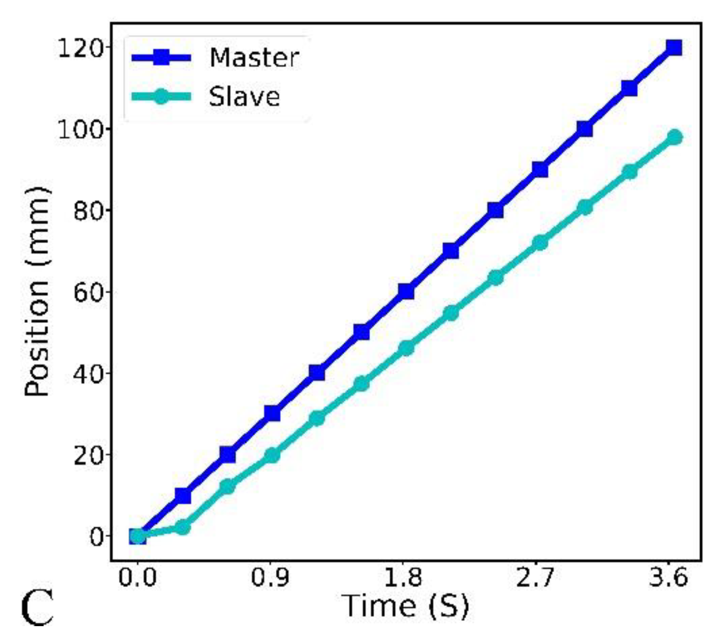
3.2. Experimental Observation of Master–Slave Position and Velocity under Uniform Translational Motion

The motion lag study was also performed for position and velocity under uniform translational motion. For this, uniform translational motion in steps of 1–10 mm was issued to the slave robot to quantify the tracking error. In addition, each trial was performed five times for each displacement step value to trigger navigation, while the robotic devices’ mean position and velocity output were recorded. In Figure 7A–C, we present the distance traveled by both master and slave platforms when displacement values of 3, 5, and 10 mm were, respectively, set. In Figure 7A, the slave device closely matched the displacement of the master platform for a translation step of 3 mm. In contrast, the slave device response was below the input command per step when actuated with a uniform displacement of 5 mm, as shown in Figure 7B. However, above 5 mm, a more visible gap exists such that it extends to the proportion shown in Figure 7C when operated under a displacement step value of 10 mm. Overall, the accruing error influences the resultant slave positions, as shown in Figure 7B,C.
In addition, the velocity trajectories of the master and slave platforms for 5 and 10 mm are presented in Figure 8A,B, respectively. In Figure 8A, the variation of the slave robot’s velocity was within the threshold of the motion gap observed in Figure 7B. This could infer that the slave’s position tracking is smooth for small displacement step values ( 3   mm ) . However, limiting an operator to this axial displacement range during catheterization could increase the procedural duration and induce boredom in interventionalists, especially when navigating through vessels with a larger diameter. This includes endovascular tool movement from within the radial vessels to the aorta. However, smaller displacement step values are essential for safe tool movement beyond the aorta and within the coronary arteries. Furthermore, this could allow the operator to choose between different displacement step values depending on the vessel diameter and the catheterization path while a steady translational motion could be achieved.
Figure 8B shows a noticeable difference when the slave robot actuates under a higher velocity, such as applying > 30 mm/s. Similarly, this correlates with the evident position-tracking error in Figure 7C. Thus, it is remarked that a velocity of 16 mm/s (or below) at the master side could suitably maintain a minimal position error during master–slave robotic catheterization. Comparing Figure 5, Figure 6, Figure 7 and Figure 8, our study suggests that both position and velocity contribute to the hysteresis observed at the slave-side robotic device during catheterization. In conclusion, Figure 5, Figure 6, Figure 7 and Figure 8 indicate that the nonlinearities and uncertainties could be higher and unbounded when applying variable displacement values. This typical scenario usually happens during robot-assisted tool catheterization. We, therefore, proposed a neural-based system for learning the dynamics of the master–slave setup to aptly determine and compensate for position error occurrences in the RCS.

4. Recurrent Neural Network Modeling

In this section, we utilized variants of recurrent neural network models, such as the LSTM and GRU networks, to learn typical motion dynamics when operating the master–slave platform. The trained network varieties can estimate the slave robot’s displacement from given input motion variables. The estimated value and an appropriate compensating value are then transmitted to the slave robotic device to achieve uniform motion mapping with the master platform. This data-driven approach requires experimental data to pre-train recurrent neural networks. Thus, we conducted a series of controlled studies similar to those described in Section 3, and describes the data processing procedures in this section.

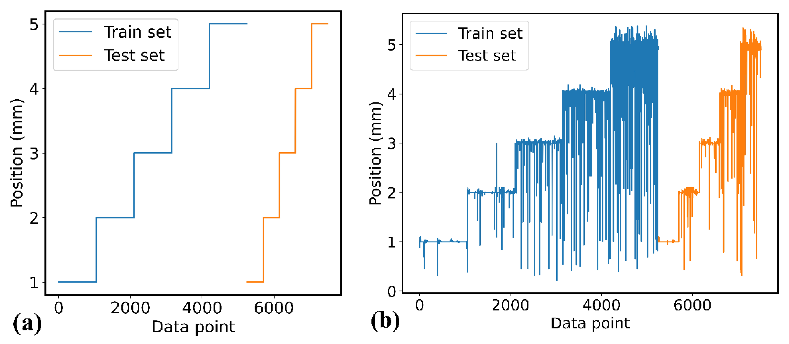
4.1. Data Pre-Processing

As highlighted in Section 3, analysis of the position and velocity illustrates better position tracking between the master and slave platforms when operated with constant displacement values.
Thus, we carried out phantom studies for these displacement values to acquire the experimental data for training the neural-based models. To ensure consistency in all data tuples, we fixed the start and end points for all the navigation trials that we performed. Motion commands from the master device emanate from custom code written in Python and executed online via the Raspberry controller. The data acquired are first pre-processed by removing empty and incomplete records that occasionally occur at the slave side. With a total of 188 experimental runs conducted, we obtained 7500 data sequences with exactly 1500 data sequences selected for each 1–5 mm discrete motion. Subsequently, each step’s master–slave motion data were divided randomly into training (70%) and test (30%) datasets.
The displacement and velocity from the master side in addition to the ratio of velocity between the master–slave devices are taken as input variables into the network to estimate the slave robot positions. The training and test datasets for the master–slave positions are shown in Figure 9. The slave robot’s response to discrete input commands is shown in Figure 9b. This typifies the occurrence of random values (errors) increasing proportionally with the magnitude of the translational motion. That is, between 1–5 mm, specifically, from 3 mm, there were increasing data points, where the output position of the slave robot were below the input command, thus symbolizing a noisy data. This is a typical response of the slave robot to higher displacement step values without position control or compensation. Furthermore, this also indicates the cause of jerks and vibrations in the slave robot during typical master-slave movements in the absence of position control methods.

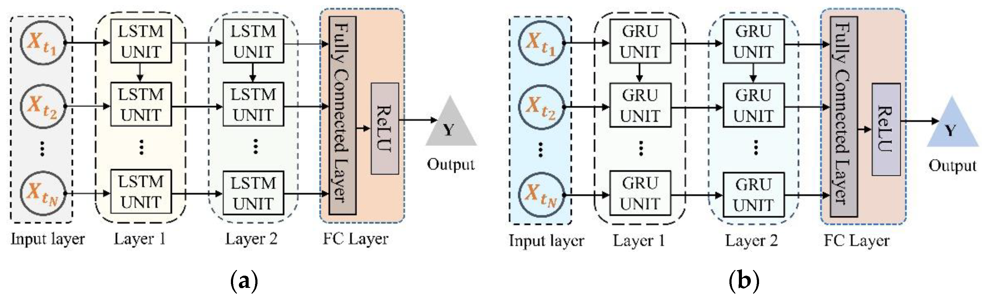
4.2. Recurrent Neural Network

The LSTM network consists of a stack of LSTM units, each equipped with a cell and three gates—a forget gate, an input gate, and an output gate that regulate information flow across the cells. An LSTM unit typically processes information in accordance with the following equations [38]. Thus, the model output at time-step t is given by h t t = 1 , 2 , , k as in Equation (1). Where σ is the logistic function with a range of zero and one that determines the ratio of information flow through each gate. The forget gate ( f ( t ) ) controls what information is retained from the previous cell state ( C ( t 1 ) ), whereas the input gate ( i ( t ) ) combines with the input-modulating gate ( C i ( t ) )—which uses a hyperbolic tangent activation (tanh) function to update the cell state to ( C ( t ) ). In addition, the output gate ( o ( t ) ) sieves the information within the new cell state ( C ( t ) ), using both the logistic and tanh functions to regulate its output, and is transferred to the hidden state ( h ( t ) ). W *   and   b *     represent the weight and bias parameter matrix in each gate, respectively. Combining the gating mechanisms enables the LSTM to extract relevant information from an input sequence.
f ( t ) =   σ   ( W f   [ h ( t 1 ) ,     x ( t )   ] + b f   ) i ( t ) =   σ   ( W i   [ h ( t 1 ) ,     x ( t )   ] + b i   ) C i ( t ) =   tan h ( W c   [ h ( t 1 ) ,     x ( t )   ] + b c )     C ( t ) = f ( t ) * C ( t 1 ) + i ( t ) *   C i ( t ) o ( t ) =   σ   ( W o   [ h ( t 1 ) , x ( t )   ] + b o ) h ( t ) = o ( t )   *   tanh ( C ( t ) )
In contrast, the stacked GRU units comprise a structure where each unit is equipped with two gates—a reset gate ( r ( t ) ) and update gate   ( z ( t ) ) . The update gate regulates what information flows into the memory using logistic function within the interval (0, 1), similar to LSTM. This controls the similarity between the previous state and the new state. The reset gate determines what percentage of the previous state is retained and how to compute the candidate hidden state (   h   ˜ ( t ) ). An elementwise operation of the update gate with the previous state ( h ( t 1 ) ) and the candidate hidden state result in the final output of the model h ( t ) is calculated as shown in the following equations below [39].
r ( t ) =   σ   ( W r   [ h ( t 1 ) ,     x ( t )   ] + b r   ) z ( t ) =   σ   ( W z   [ h ( t 1 ) ,     x ( t )   ] + b z   ) h ˜ ( t ) = tan h ( W h   [ r ( t )   * h ( t 1 ) ,     x ( t )   ] + b h ) h ( t ) = z ( t )   * h ( t 1 ) + ( 1 z ( t ) ) * h ˜ ( t )

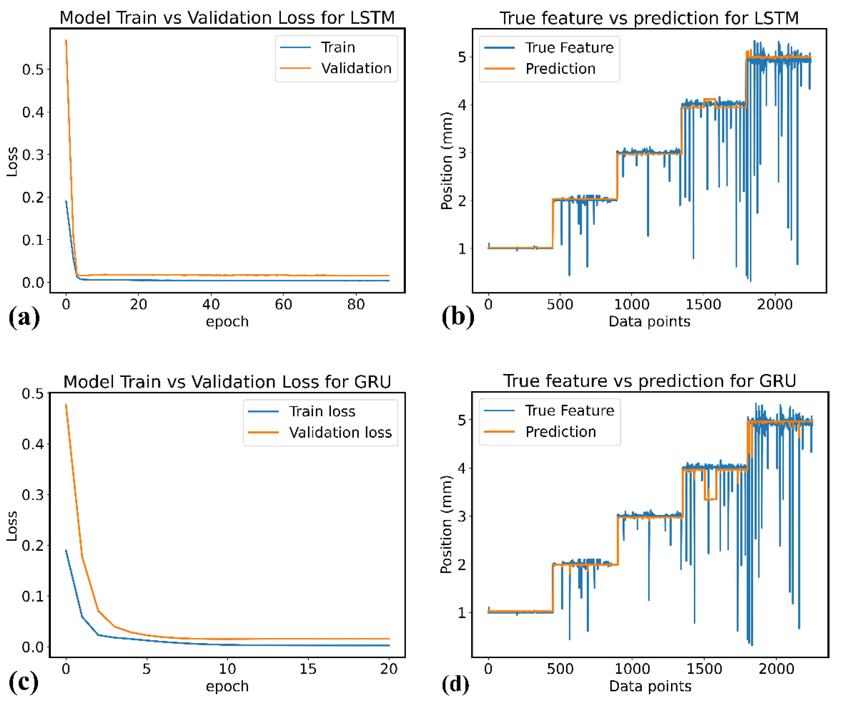
4.3. Model Training and Evaluation

The RNN models were implemented in Python using the Keras library and the TensorFlow platform. The LSTM model has an input layer ( N   × 3 × 3 ), two hidden layers with 32 units each, and a fully connected layer, which outputs a predicted value using the rectified linear unit (ReLU) activation function, as shown in Figure 10a. The LSTM unit can determine important features from an input sequence and keep such information in its memory. To train the model, experimental data for different step values were stacked together with feature scaling performed on the data. The model was trained with a batch size of 32 for 90 epochs, while 20% of the training set was used for validation. The learning rate was set to 1 × 10 4 with a time step of three and the Adam optimizer algorithm employed. Similarly, the GRU model has an input layer, two hidden layers with 16 neurons each, and a fully connected layer with the ReLU activation function, as shown in Figure 10b. The learning rate and batch size were 1 × 10 4 and 24, while the model was trained for 20 epoch with the chosen Adam optimizer algorithm.
Furthermore, the description of the two quantitative metrics used to evaluate the models’ performance is stated below, with their corresponding values given in Table 2.
  • Mean Absolute Error: The mean absolute error indicates the average sum of the absolute difference between the actual slave robot position ( y i ) and the predicted position ( x i ), as given in Equation (3).
MAE = 1 N   i = 1 N | y i x i |
  • Mean Square Error: The mean square error is the average of the squared error values between the model’s prediction and the slave robot response, represented by Equation (4).
MSE = 1 N   i = 1 N ( y i y ^ ) 2
Based on the error values (in Table 2), the RNN models have comparative performance. The models’ training, validation, and prediction performances are shown in Figure 11a–d. Figure 11 indicates that the validation loss for each model was less than 2% under each category, while the models aptly predicted the intended slave displacement for each set-value, i.e., 1–5 mm. The LSTM model has a longer training time compared with the GRU model, which utilized the least number of neurons and epochs. Thus, we suggest that either of the models could be deployed for position prediction and error compensation to eliminate motion lag between the master–slave platform during robot-assisted tool navigation.

5. Experimental Study and Results

We performed in-silico and hardware-based experiments to validate the performance of the RNN-based models when deployed within the slave robot. In addition, we implemented an open-loop control using the models’ prediction for error compensation to achieve identical master–slave position mapping for uniform and varying input commands.

5.1. In-Silico Modeling and Evaluation

The in-silico experiments performed in CoppeliaSim Edu (Coppelia Robotics Ltd., Zurich, Switzerland) involve the conversion of the slave robot’s 3D CAD model to a unified robot description format (URDF), which is then assembled within the simulation scene, as shown in Figure 12. We parameterized the static and dynamic properties of the robot to mimic the translation mode of the slave robot. To facilitate the position control of the device, a prismatic joint and the global positioning system (GPS) provided feedback about the device’s position and orientation. To evaluate the RNN model’s performance, a uniform displacement command (5 mm) is transmitted to the slave robot, while a random value (rand_val) represented by Equation (5) generates the uncertainties resulting in stepwise error. For each step, the RNN model predicts the slave robot’s response based on input motion variables prior to the robot’s translation. Afterwards, the difference between the model’s prediction and the actual robot displacement is added to the initial slave robot’s movement with the final error computed per step. This ensures that the slave robot reproduces exact position commands received from the master platform, thereby eliminating accruing errors within the slave robot along its traveling distance.
rand _ val =   σ   × n p .   random . normal ( 0 ,   1 )

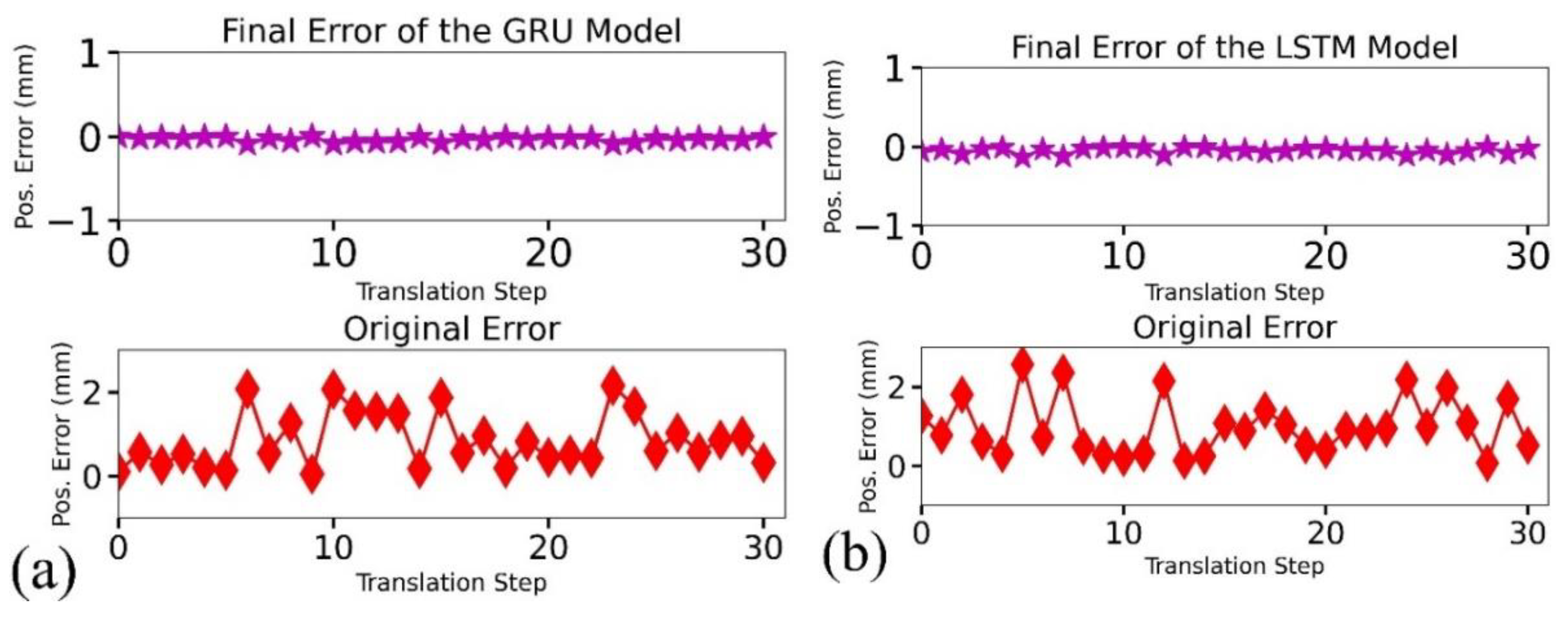
5.2. In-Silico Results and Evaluation

The in-silico analyses of the GRU and LSTM-based models are presented in Figure 13. In Figure 13a, a comparison of the slave robot’s original and final response for a traveling distance of 150 mm with a scalar value ( σ ) of 1.0 mm is shown. Although the original error rose to 40% (2.0 mm) of the input command for some steps, the minimum and maximum final errors were 0.001 mm and 0.1 mm (2% of the input command) per step. The figure shows that the GRU-based controller could predict the expected slave robot response and then utilize this to regress the initial position error. Similarly, in Figure 13b, we present the performance of the LSTM model when the slave robot actuates under a uniform motion for a distance of 150 mm with a scalar value of 1.5 mm. The model predicted values indicate that the LSTM-based controller makes a good prediction of the slave robot response for a typical displacement of 5.0 mm, with a resultant final error of 1.25 mm. Compared with Table 1, the neural-based models ensure higher precision and accuracy of master–slave position-tracking capability. Overall, the models are suitable for position prediction and error compensation within RCSs.

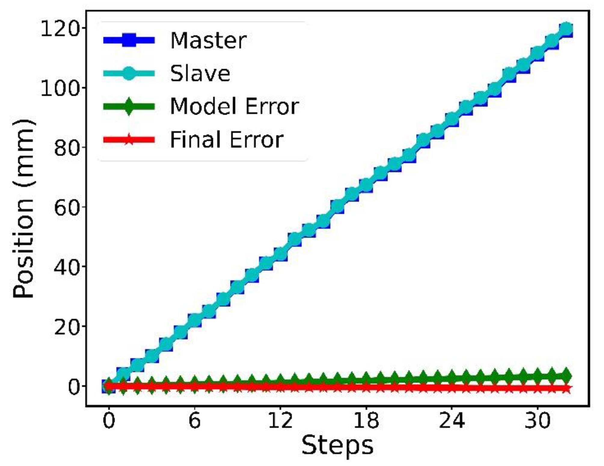
5.3. In-RCS Results and Evaluation

To validate the real-time usability of the learning-based models in the RCS, we utilized the Jetson AGX Orin Development Kit (NVIDIA, Santa Clara, CA, USA) for the slave robot operation, and evaluated the model’s performance under uniform and varying input commands using the control block diagram presented in Figure 14. For a typical master’s displacement ( M p ), velocity ( M v ), and the velocity ratio ( V r ), the RNN model makes an appropriate prediction ( R N N p ) and performs an error check. In addition, the slave robot receives a compensated displacement value (that incorporates the difference between the model’s prediction and the input command). Afterwards, the slave robot actuates for the given step and the difference between the master and slave position ( S p ) is computed as the final error (motion lag) for that step. In Figure 15, we present the experimental setup for the evaluation of the above control approach within the RCS using the neural-based controllers.
The average performance of the GRU model for varying displacement commands (3–5 mm) and a traveling distance of 120 mm by the slave robot is presented in Figure 16. The choice of 3–5 mm aligns with the experimental observation of an increasing motion gap between the master and slave robot under uniform translational motion as presented in Figure 7A,B. The figure shows the positive impact of the real-time compensating values for input displacement such as 5 mm, thus maintaining the slave robot’s smooth translational motion with a minimum and maximum error of 0.014 and 0.04 mm, respectively, as shown in Figure 16. This infers the neural-based model’s suitability for prediction and compensation tasks within the slave robot during catheterization and the realization of an equivalent master–slave position trajectory for displacement steps above 1 mm.

6. Discussion

This study further supports our approach to real-time detection and elimination of the slave robot’s position errors during catheterization. We demonstrated that the control approach has the potential to create steady master–slave motion and contribute to procedural safety during R-PCI procedures. In addition, a comparative analysis of existing control approaches for master–slave position tracking shows that the neural-based controllers have a much lower maximum error compared with MLP-PID, ADRC, and FSMC for in-RCS experiments, as indicated in Table 3. Although, RL-PID has the best performance, the control method was only verified with simulation experiments. Overall, we have presented a data-driven control approach for master–slave position tracking, which leverages on neural network capability for robust features learning and representation from training examples, thus yielding a higher precision, accuracy, and lower percentage error.
Although single-board computers facilitate easy mobility of the robotic device, we experienced hardware limitations deploying RNN models within Raspberry PI for real-time error predictions. This study suggests the need for more powerful single-board computers. The recent launch of Jetson AGX Orin seems timely; however, large-scale validation is still needed. In addition, machine-learning methods using intelligent agents such as reinforcement learning would be operable within the RCS for state-based navigation or task-specific autonomous control. Furthermore, adding reliable proximal and distal force navigation data would enable learning the master–slave robot kinematics as well as tool dynamics within the vasculature, which could lead to the development of a robust model with the potential realization of closed-loop control during R-PCI. At present, acquiring operator-based motion data is time-consuming and laborious. This is because fewer displacement steps are covered within a full stroke under varying motion (Figure 7A–C) compared with uniform translational motion (Figure 9a–c). However, such data contain a higher degree of nonlinearities, thus are closer to real-world characterization of the slave robot’s position error. While intraluminal navigation safety is at the top of patients’ safety concerns during minimally invasive procedures, recent investigations show potential for task-specific autonomy for tool navigation during R-PCIs.
In this study, we described the development of a custom-built master–slave RCS to navigate endovascular tools. We further analyzed the causative factors for position errors at the slave side of the robotic system using the displacement values at both master and slave sides, their velocity, and backlash gaps. Thus, we proposed and validated using learning-based control models for online error compensation in the RCS. The RNN models were trained with master–slave forward motion profiles recorded from the RCS. Furthermore, this study focused on the characterization and control of translational motion in the RCS. However, a hybrid of translational and rotary motion is essential for semi-autonomous navigation. To achieve this, high-resolution rotary encoders would be essential. Therefore, further studies will seek to incorporate high-resolution rotary encoders and consolidate the characterization and control of rotary motion. This would provide for the development of a robust learning-based controller for translational and rotary motion during R-PCI. In conclusion, this study has shown the feasibility and self-adaptability of neural-based controllers with verification for RCSs towards achieving smooth translational motion during minimally invasive treatment of CAD.

Author Contributions

Conceptualization, O.M.O. and T.O.A.; methodology, T.O.A.; software, T.O.A. and G.Y.; validation, T.O.A., W.D. (Wenke Duan) and X.C.; formal analysis, T.O.A., O.M.O. and W.D. (Wenjing Du); investigation, T.O.A. and O.M.O.; resources, W.D. (Wenke Duan) and X.C.; data curation, T.O.A.; writing—original draft preparation, T.O.A.; writing—review and editing, O.M.O. and T.O.A.; visualization, T.O.A. and L.W.; supervision, L.W. and O.M.O.; project administration, L.W. and W.D (Wenjing Du); funding acquisition, L.W. All authors have read and agreed to the published version of the manuscript.

Funding

This research was funded in parts by the National Key Research and Development Program of China under Grant 2019YFB1311700, the National Natural Science Foundation of China under Grants (#U1713219, #61950410618), the Shenzhen Natural Science Foundation under Grant JCYJ20190812173205538, and in part by the CAS PIFI Fellowship.

Institutional Review Board Statement

Not applicable.

Informed Consent Statement

Not applicable.

Data Availability Statement

Not applicable.

Conflicts of Interest

The authors declare no conflict of interest.

References

  1. Virani, S.S.; Alonso, A.; Aparicio, H.J.; Benjamin, E.J.; Bittencourt, M.S.; Callaway, C.W.; Carson, A.P.; Chamberlain, A.M.; Cheng, S.; Delling, F.N.; et al. Heart Disease and Stroke Statistics-2021 Update A Report from the American Heart Association. Circulation 2021, 143, E254–E743. [Google Scholar] [CrossRef]
  2. Gatto, L.; Prati, F. Subclinical atherosclerosis: How and when to treat it? Eur. Hear. J. Suppl. 2020, 22, E87–E90. [Google Scholar] [CrossRef]
  3. Cohn, W.E.; Frazier, O.H.; Mallidi, H.R.; Cooley, D.A. Coronary Artery Disease, Cardiovascular Medicine; Willerson, J.T., Holmes, D.R., Jr., Eds.; Springer: London, UK, 2015; p. 657. [Google Scholar] [CrossRef]
  4. Akinyemi, T.O.; Omisore, O.M.; Duan, W.; Lu, G.; Al-Handerish, Y.; Han, S.; Wang, L. Fiber Bragg Grating-Based Force Sensing in Robot-Assisted Cardiac Interventions: A Review. IEEE Sens. J. 2021, 21, 10317–10331. [Google Scholar] [CrossRef]
  5. Watson, T.J.; Ong, P.J.L.; Tcheng, J.E. Primary Angioplasty: A Practical Guide; Springer: Singapore, 2018. [Google Scholar]
  6. Bergman, P.; Blacker, S.J.; Kottenstette, N.; Saber, O.; Sokhanvar, S. Robotic-Assisted Percutaneous Coronary Intervention. In Handbook of Robotic and Image-Guided Surgery; Elsevier: Amsterdam, The Netherlands, 2020; pp. 341–362. [Google Scholar]
  7. Akinyemi, T.O.; Omisore, O.M.; Duan, W.; Lu, G.; Du, W.; Alhanderish, Y.; Li, Y.; Wang, L. Development of a Millinewton FBG-Based Distal Force Sensor for Intravascular Interventions. In Proceedings of the 16th International Conference on Control, Automation, Robotics and Vision (ICARCV), Shenzhen, China, 13–15 December 2020; IEEE: New York, NY, USA, 2021; pp. 511–515. [Google Scholar] [CrossRef]
  8. Kalra, A.; Bhatt, D.L.; Kleiman, N.S. A 24-Month Interventional Cardiology Fellowship: Learning Motor Skills Through Blocked Repetition. JACC Cardiovasc. Interv. 2017, 10, 210–211. [Google Scholar] [CrossRef]
  9. Lee, C.W.J.; Rao, A. Current training in Cardiac devices–a Cardiology trainee perspective: A questionnaire survey. MedEdPublish 2017, 6, 130. [Google Scholar]
  10. Omisore, O.M.; Akinyemi, T.; Duan, W.; Wang, L. A Novel Sample-efficient Deep Reinforcement Learning with Episodic Policy Transfer for PID-Based Control in Cardiac Catheterization Robots. October 2021. Available online: http://arxiv.org/abs/2110.14941 (accessed on 1 June 2022).
  11. Kinnaird, T.; Kwok, C.S.; Kontopantelis, E.; Ossei-Gerning, N.; Ludman, P.; de Belder, M.; Andreson, R.; Mamas, M.A. Incidence, determinants, and outcomes of coronary perforation during percutaneous coronary intervention in the United Kingdom Between 2006 and 2013. Circ. Cardiovasc. Interv. 2016, 9, e003449. [Google Scholar] [CrossRef]
  12. Omisore, O.M.; Duan, W.; Akinyemi, T.; Han, S.; Du, W.; Alhanderish, Y.; Wang, L. Design of a Master-Slave Robotic System for Intravascular Catheterization during Cardiac Interventions. In Proceedings of the International Conference on Control, Automation, Robotics and Vision (ICARCV), Shenzhen, China, 13–15 December 2020; IEEE: New York, NY, USA, 2021; pp. 996–1000. [Google Scholar]
  13. Weisz, G.; Metzger, D.C.; Caputo, R.P.; Delgado, J.A.; Marshall, J.J.; Vetrovec, G.W.; Reisman, M.; Waksman, R.; Granada, J.F.; Novack, V.; et al. Safety and feasibility of robotic percutaneous coronary intervention: PRECISE (percutaneous robotically-enhanced coronary intervention) study. J. Am. Coll. Cardiol. 2013, 61, 1596–1600. [Google Scholar] [CrossRef] [Green Version]
  14. Smitson, C.C.; Ang, L.; Pourdjabbar, A.; Reeves, R.; Patel, M.; Mahmud, E. Safety and feasibility of a novel, second-generation robotic-assisted system for percutaneous coronary intervention: First in-human report. J. Invasive Cardiol. 2018, 30, 152–156. [Google Scholar] [CrossRef]
  15. CorPath GRX System Operator’s Manual. Available online: https://www.roboticpci.com/assets/Documents/150-07702_Rev_C_CorPath_GRX_Operator’s_Manual.pdf (accessed on 31 August 2022).
  16. Dupont, P.E.; Nelson, B.J.; Goldfarb, M.; Hannaford, B.; Menciassi, A.; O’Malley, M.K.; Simaan, N.; Valdastri, P.; Yang, G.Z. A decade retrospective of medical robotics research from 2010 to 2020. Sci. Robot. 2021, 6, 8017. [Google Scholar] [CrossRef]
  17. Akinyemi, T.O.; Omisore, O.M.; Duan, W.; Lu, G.; Al-Handerish, Y.; Han, S.; Wang, L. Towards a Fiber Bragg Grating-Based Force Sensing in Robot-Assisted Cardiac Interventions. IEEE Sens. Lett. 2022, 21, 5000104. [Google Scholar] [CrossRef]
  18. Al-Ahmad, O.; Ourak, M.; Smits, J.; Jeanquart, S.; Deserranno, N.; Bernhard, F.; Kassahun, Y.; Yu, B.; Vander Poorten, E. Development of an Innovative Sleeve-Based Robotic Catheter Driver. In Proceedings of the 8th Joint Workshop on New Technologies for Computer/Robot Assisted Surgery, London, UK, 10–11 September 2018; pp. 2–3. [Google Scholar]
  19. Payne, C.J.; Rafii-Tari, H.; Yang, G.-Z. A force feedback system for Endovascular catheterization. In Proceedings of the International Conference on Intelligent Robots and Systems, Vilamoura-Algarve, Portugal, 7–12 October 2012; IEEE: New York, NY, USA, 2012; pp. 1298–1304. [Google Scholar]
  20. Cha, H.J.; Yi, B.J.; Won, J.Y. An assembly-type master-slave catheter and guidewire driving system for vascular intervention. Proc. Inst. Mech. Eng. H 2017, 231, 69–79. [Google Scholar] [CrossRef] [PubMed]
  21. Thakur, Y.; Bax, J.S.; Holdsworth, D.W.; Drangova, M. Design and performance evaluation of a remote catheter navigation system. IEEE Trans. Biomed. Eng. 2009, 56, 1901–1908. [Google Scholar] [CrossRef] [PubMed]
  22. Richter, F.; Orosco, R.K.; Yip, M.C. Motion scaling solutions for improved performance in high delay surgical teleoperation. In Proceedings of the International Conference on Robotics and Automation Montreal, Montreal, QC, Canada, 20–24 May 2019; IEEE: New York, NY, USA, 2019; pp. 1590–1595. [Google Scholar]
  23. Sankaran, N.K.; Chembrammel, P.; Siddiqui, A.; Snyder, K.; Kesavadas, T. Design and Development of Surgeon Augmented Endovascular Robotic System. IEEE Trans. Biomed. Eng. 2018, 65, 2483–2493. [Google Scholar] [CrossRef] [PubMed]
  24. Ma, X.; Zhou, J.; Zhang, X.; Zhou, Q. Development of a Robotic Catheter Manipulation System Based on BP Neural Network PID Controller. Appl. Bionics Biomech. 2020, 2020, 8870106. [Google Scholar] [CrossRef] [PubMed]
  25. Guo, J.; Jin, X.; Guo, S.; Du, W. Study on the tracking performance of the vascular interventional surgical robotic system based on the fuzzy-PID controller. In Proceedings of the International Conference on Mechatronics and Automation (ICMA), Takamatsu, Japan, 6–9 August 2017; IEEE: New York, NY, USA, 2017; pp. 29–34. [Google Scholar]
  26. Omisore, O.M.; Han, S.; Ren, L.; Wang, L. A fuzzy-PD model for master-slave tracking in teleoperated robotic surgery. In Proceedings of the Biomedical Circuits and Systems Conference, Shanghai, China, 17–19 October 2016; IEEE: New York, NY, USA, 2017. [Google Scholar]
  27. Omisore, O.M.; Han, S.P.; Ren, L.X.; Wang, G.S.; Ou, F.L.; Li, H.; Wang, L. Towards Characterization and Adaptive Compensation of Backlash in a Novel Robotic Catheter System for Cardiovascular Interventions. IEEE Trans. Biomed. Circuits Syst. 2018, 12, 824–838. [Google Scholar] [CrossRef]
  28. Wang, H.; Chang, J.; Yu, H.; Liu, H.; Hou, C.; Lu, H. Research on a Novel Vascular Interventional Surgery Robot and Control Method Based on Precise Delivery. IEEE Access 2021, 9, 26568–26582. [Google Scholar] [CrossRef]
  29. Yu, H.; Wang, H.; Chang, J.; Niu, J.; Wang, F.; Yan, Y.; Tian, H.; Fang, J.; Lu, H. A Novel Vascular Intervention Surgical Robot Based on Force Feedback and Flexible Clamping. App. Sci. 2021, 11, 611. [Google Scholar] [CrossRef]
  30. Guo, S.; Song, Y.; Yin, X.; Zhang, L.; Tamiya, T.; Hirata, H.; Ishihara, H. A novel robot-assisted endovascular catheterization system with haptic force feedback. IEEE Trans. Robot. 2019, 35, 685–696. [Google Scholar] [CrossRef]
  31. Hasanzadeh, S.; Janabi-Sharifi, F.; Keenan, P. Backlash characterization and position control of a robotic catheter manipulator using experimentally-based kinematic model. Mechatronics 2017, 44, 94–106. [Google Scholar] [CrossRef]
  32. Omisore, O.M.; Han, S.; Zhou, T.; Al-Handarish, Y.; Du, W.; Ivanov, K.; Wang, L. Learning-based Parameter Estimation for Hysteresis Modeling in Robotic Catheterization. In Proceedings of the 41st IEEE Conference of Engineering in Medicine and Biology Society, Berlin, Germany, 23–27 July 2019; IEEE: New York, NY, USA, 2019; pp. 5399–5402. [Google Scholar]
  33. Beaman, C.B.; Kaneko, N.; Meyers, P.M.; Tateshima, S. A review of robotic interventional neuroradiology. Am. J. Neuroradiol. 2021, 42, 808–814. [Google Scholar] [CrossRef]
  34. Bai, W.; Cursi, F.; Guo, X.; Huang, B.; Lo, B.; Yang, G.Z.; Yeatman, E.M. Task-Based LSTM Kinematic Modeling for a Tendon-Driven Flexible Surgical Robot. IEEE Trans. Med. Robot. Bionics 2022, 4, 339–342. [Google Scholar] [CrossRef]
  35. Wu, D.; Zhang, Y.; Ourak, M.; Niu, K.; Dankelman, J.; Vander Poorten, E. Hysteresis Modeling of Robotic Catheters Based on Long Short-Term Memory Network for Improved Environment Reconstruction. IEEE Rob. Autom Lett. 2021, 6, 2106–2113. [Google Scholar] [CrossRef]
  36. Cursi, F.; Bai, W.; Yeatman, E.M.; Kormushev, P. Model Learning With Backlash Compensation for a Tendon-Driven Surgical Robot. IEEE Rob. Autom. Lett. 2022, 7, 7958–7965. [Google Scholar] [CrossRef]
  37. Choi, J.; Park, S.; Kim, Y.H.; Moon, Y.; Choi, J. A vascular intervention assist device using bi-motional roller cartridge structure and clinical evaluation. Biosensors 2021, 11, 329. [Google Scholar] [CrossRef] [PubMed]
  38. Józefowicz, R.; Zaremba, W.; Sutskever, I. An Empirical Exploration of Recurrent Network Architectures. In Proceedings of the 32nd International Conference on Machine Learning, ICML, Lille, France, 6–11 July 2015; JMLR: Massuchesetts, MA, USA; pp. 2342–2350. [Google Scholar]
  39. Cho, K.; Van Merriënboer, B.; Bahdanau, D.; Bengio, Y. On the properties of neural machine translation: Encoder-decoder approaches. arXiv 2014, arXiv:1409.1259. [Google Scholar]
  40. Zhou, W.; Guo, S.; Guo, J.; Meng, F.; Chen, Z. ADRC-Based Control Method for the Vascular Intervention Master–Slave Surgical Robotic System. Micromachines 2021, 12, 1439. [Google Scholar] [CrossRef]
Figure 1. Catheter driver mechanisms using (A) friction roller, (B) gripping and translation, (C) magnetic actuation. Adapted with permission from Ref. [33]. © 2021, American Society of Neuroradiology.
Applsci 12 10936 g001
Figure 2. The design and assembling of the master platform. (a) The master device’s outer casing and exterior components, and (b) the inner view and main components of the master robotic device.
Applsci 12 10936 g002
Figure 3. The design and assembling of the slave robot platform. (a) The exterior components of the slave platform, and (b) the clamping mechanism and interior components of the slave robotic device.
Applsci 12 10936 g003
Figure 4. The master–slave robotic platform communication scheme.
Applsci 12 10936 g004
Figure 5. Master–slave position trajectories based on an operator’s hand motion for a distance of (A) 70 mm, (B) 100 mm, and (C) 120 mm.
Applsci 12 10936 g005
Figure 6. Master–slave velocity based on an operator’s hand motion for a distance of (A) 70 mm and (B) 120 mm.
Applsci 12 10936 g006
Figure 7. Master–slave position trajectories based on uniform displacement values of (A) 3 mm, (B) 5 mm, and (C) 10 mm.
Applsci 12 10936 g007aApplsci 12 10936 g007b
Figure 8. Master–slave velocity trajectories based on uniform displacement values of (A) 5 mm and (B) 10 mm. Inset shows the enlarged view of the master-slave velocity trajectories for a uniform displacement of 5 mm.
Applsci 12 10936 g008
Figure 9. Training and test data split for (a) master position (as part of the input variable) and (b) the slave position (target variable).
Applsci 12 10936 g009
Figure 10. A stacked 2-layer architecture for slave robot’s position prediction and compensation using (a) LSTM model and (b) GRU model.
Applsci 12 10936 g010
Figure 11. The performance of the RNN models: (a) training and validation loss for the LSTM model, (b) prediction on the test set based on the LSTM model, (c) training and validation loss for the GRU model, (d) prediction on the test set based on the GRU model.
Applsci 12 10936 g011
Figure 12. The slave device assembly and translational motion simulation in CoppeliaSim.
Applsci 12 10936 g012
Figure 13. The original position error of the slave robotic device is shown in the lower panel compared with (a) GRU-based and (b) LSTM-based predictions for a distance of 150 mm with a translational step of 5 mm.
Applsci 12 10936 g013
Figure 14. Control block with error compensation for the slave robot.
Applsci 12 10936 g014
Figure 15. The hardware setup for experimental validation of the neural-based models within the RCS using Jetson Orin as the slave device’s processor.
Applsci 12 10936 g015
Figure 16. The master–slave position trajectory for a distance of 120 mm under varying input commands with the GRU model prediction and error compensation within the slave robot.
Applsci 12 10936 g016
Table 1. Average position error of the slave robotic device for given distances.
Distance (mm)Error (mm)Resultant Error (%)
303.84 ± 2.0319.90
456.38 ± 2.3014.83
707.43 ± 3.7214.66
10010.67 ± 4.3015.11
12013.14 ± 6.1115.51
Table 2. MAE and MSE for the LSTM and GRU models.
ModelMAE (mm)MSE (mm2)
LSTM0.08250.0958
GRU0.09060.0964
Table 3. Performance evaluation of the proposed method with existing studies.
AuthorsControl MethodExperiment TypeMax. Error (mm)
Ma et al. [24]MLP-PIDSimulation/in-RCS1.50
Omisore et al. [10]RL-PIDSimulation0.003
Zhou et al. [40]ADRCRCS0.87
Wang et al. [28]FSMCSimulation0.65
This studyLSTM/GRUSimulation/in-RCS0.04
Note MLP-PID—multi-layer perceptron-based PID controller; RL-PID—reinforcement learning-based PID controller; ADRC—active disturbance rejection control; FSMC—fuzzy sliding mode controller.
Publisher’s Note: MDPI stays neutral with regard to jurisdictional claims in published maps and institutional affiliations.

