Article

A Theoretical and Experimental Investigation of High-Frequency Ultrasonic Vibration-Assisted Sculpturing of Optical Microstructures

1
State key Laboratory of Ultra-Precision Machining Technology, Department of Industrial and Systems Engineering, The Hong Kong Polytechnic University, Hung Hom, Kowloon, Hong Kong, China
2
Son-x Gmbh, 52078 Aachen, Germany
*
Authors to whom correspondence should be addressed.
Appl. Sci. 2022, 12(21), 10937; https://doi.org/10.3390/app122110937
Submission received: 27 September 2022 / Revised: 15 October 2022 / Accepted: 26 October 2022 / Published: 28 October 2022

Abstract

:

Featured Application

The outcome of the study provides an efficient machining way to fabricate optical microstructure mold made of difficult-to-machine materials which could be used for mass production of optical functional components.

Abstract

Ultrasonic vibration-assisted cutting (UVAC) has been regarded as a promising technology to machine difficult-to-machine materials. It allows for a sub-micrometer form accuracy and surface roughness in the nanometer range. In this paper, high-frequency vibration-assisted sculpturing is used to efficiently fabricate quadrilateral microlens array with sharp edges, instead of using slow-slide-servo diamond turning with vibration. The machining principle of diamond sculpturing, the cutting dynamics of ultrasonic vibration, and the tool edge on the theoretical form error between the designed structure and the machined structure were investigated for this technique. Then, the quadrilateral microlens array was machined by means of conventional sculpturing (CS) and high-frequency ultrasonic vibration-assisted sculpturing (HFUVAS), respectively, followed by a study of the cutting performances including form accuracy, the surface morphology of the machined structure, and the tool wear. Results showed that conventional sculpturing fabricated microlens array with poor form accuracy and surface finish due to couple effect of material adhesion and tool wear, while the high-frequency ultrasonic vibration-assisted sculpturing achieved optical application level with sub-micrometer form accuracy and surface roughness of nanometer due to reduction of material adhesion and tool wear resulted from high-frequency intermittent cutting.

1. Introduction

The demand for ultraprecision machining of micro-structured functional surfaces, such as microlens array, pyramid array, retroreflective array, and diffraction grating, has been increasing in many advanced optical products and devices. Ultra-precision machining technology, including slow slide servo [1], fast tool servo [2], and ultra-precision milling [3] is applicable to the machining of these functional structures with complex geometry. To enhance the widespread use of these structured surfaces, high temperature forming processes such as injection molding or compression molding is considered as an effective and efficient method. The premise of this technology is to fabricate a mold with difficult-to-machine materials such as steel. However, direct diamond machining of steel with the super finish is not amenable due to extreme chemical tool wear [4]. As a result, UVAC has been applied due to reduced tool wear [5,6] and better surface finish [7,8].
There are several UVAC methods to fabricate complex structured surfaces on difficult-to-machine materials. Suzuki and Zhang developed a novel structure sculpturing method by modifying vibration amplitude according to workpiece geometry in an ultrasonic elliptical vibration cutting process so complex micro/nanostructures were successfully machined on hardened steel without moving the Z-axis slide towards and backward the workpiece [9,10]. To enhance geometric complexity as well as improve machining efficiency, a fast tool servo was integrated with ultrasonic vibration-assisted cutting. Consequently, the double-frequency vibration cutting method has been proposed, in which the system consists of one-dimension (1D) low-frequency vibration used to generate the complex tool path for the workpiece geometry acting as a fast tool servo, and a high-frequency vibration responsible for improving the machinability of the workpiece materials [11,12]. Kurniawan et al. [13] added ultrasonic elliptical vibration cutting to a low-frequency setup for texturing micro-dimple patterns on steel. Regarding slow-slide-servo machining, a few scholars applied the state-of-art and high-frequency ultrasonic tooling system (UTS2) to machine structures with smooth tool paths such as sinusoidal grids on hard-to-machine materials including steel [14] and high entropy alloy [15], achieving sub-micrometer form accuracy and surface finish with nanometer roughness.
Slow-slide-servo based machining in which the Z-axis slide moves out and in according to the workpiece geometry to generate the structured surface is a more convenient processing method compared with the structure sculpturing method or the double-frequency vibration cutting method, with no need for extra signal control operation or fast tool servo equipment. However, as the Z-axis slide has a large volume and inertia, the tool path is expected to be smooth enough to avoid overshoot and vibration induced by the quick acceleration of the Z-axis slide. Unfortunately, it is hard or impossible to ensure a smooth tool path for slow-slide-servo diamond turning of complex structures with sharp edges such as quadrilateral microlens array since the tool path is generated randomly along a spiral line. Mukaida et al. [16] proposed a slow-slide-servo segment turning method to cut hexagonal microlens arrays by multiple groups so that a smooth approaching zone for each lenslet could be established to avoid the sudden change in direction of the tool path. However, it requires reconduction of the 3D structure to add the smooth approaching zone and it is time-consuming due to the need for multiple times of machining. In contrast, in diamond sculpturing, the cutting tool moves linearly to machine the lenslets by one tool path instead of multiple tool paths enveloping the lenslets as diamond turning. As a result, the target profile is simpler and more regular so that a smooth tool path can be generated by data processing to avoid overshoot or vibration of the cutting tool. More importantly, the machining time can be reduced considerably to improve machining efficiency.
A few studies have been made on machinable material via conventional diamond sculpturing. Yuan et al. [17] conducted a series of sculpturing experiments and found that the slope angle of the tool path played a key role in the determination of the material spring back and the burr formation, then proposed a theory to explain the tool indentation effect in diamond cutting of optical micro-structured surfaces. Li et al. [18] conducted the sculpturing of a microlens array on an intrinsic silicon substrate. Although the surface roughness of the machined structure was in the nanometer range, form accuracy was poor, which suggested that it might be difficult for conventional sculpturing to accurately machine hard materials. Currently, little research has been found to provide new insight into the diamond sculpturing of microlens arrays with sharp edges on steel materials. Reduced tool wear [19], optimal surface finish [20] and fine form accuracy are the concerns in the machining process. To improve machinability and reduce tool wear in the machining of microlens array on steel, the high-frequency ultrasonic vibration-assisted sculpturing was applied. As a result, the purpose of this research is to conduct a theoretical and experimental investigation of high-frequency ultrasonic vibration-assisted sculpturing of optical microstructures on steel workpieces. The machining principle of diamond sculpturing, as well as the cutting dynamics of ultrasonic vibration on the theoretical form error in diamond sculpturing, was analyzed and determined. Form accuracy, the surface morphology of the machined structures, and the tool wear were measured and analyzed. Furthermore, conventional sculpturing was also conducted for comparison.

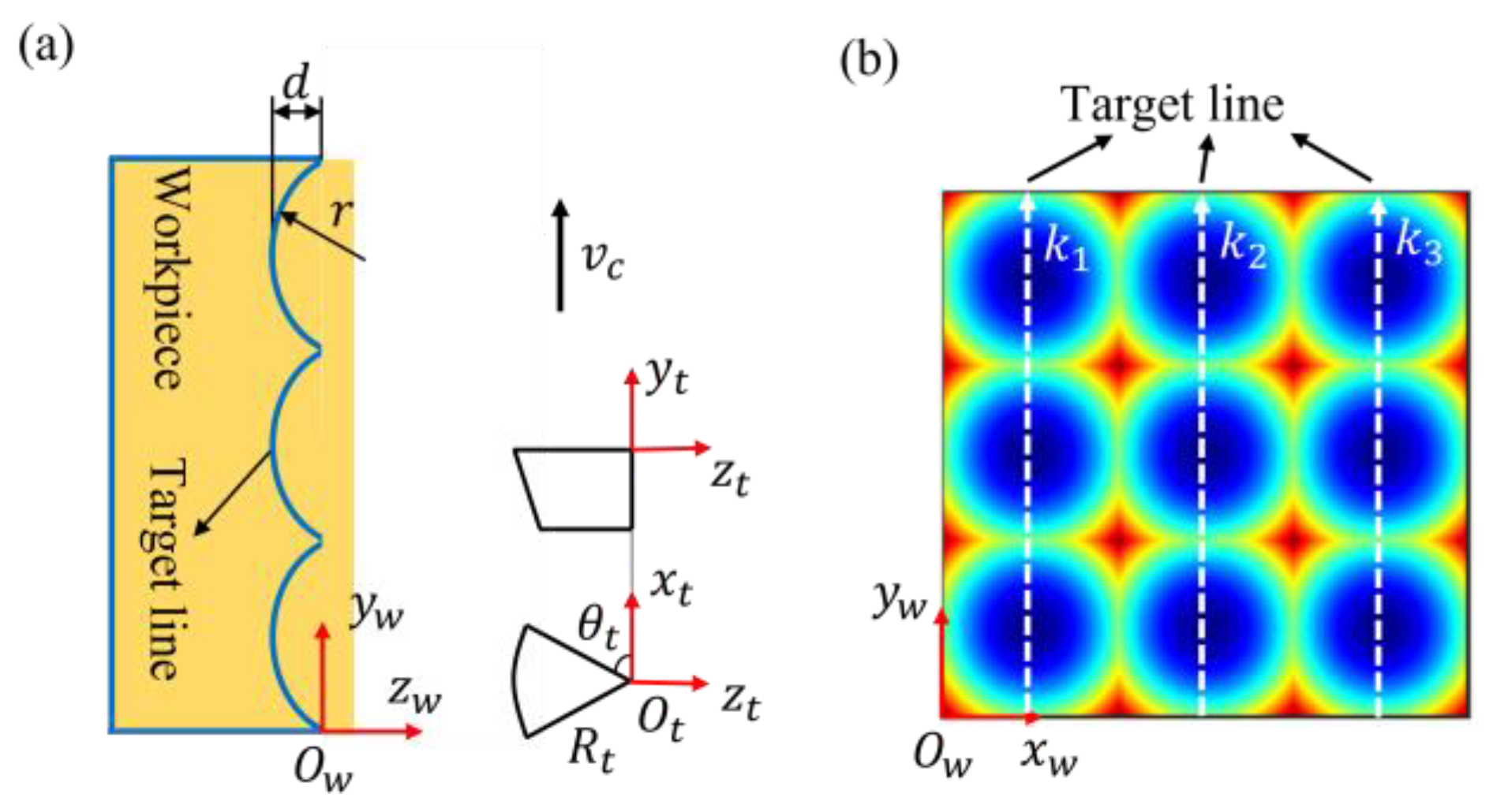
2. Principle and Theoretical Form Error of Ultrasonic Vibration-Assisted Sculpturing of Quadrilateral Microlens Array

Quadrilateral microlens array can be described by Equation (1):
z x , y = x p 1 i 0.5 2 + y p 2 j 0.5 2 r + r 2 x p 1 i 0.5 2 y p 2 j 0.5 2  
where i and j are the sequence number of the lenslet in the x and y direction, r is the microlens radius. p 1 and p 2 are pitches of the lenslet in the x and y direction, which were set as the same value in this work.
Figure 1 presents the configuration of the cutting system and tool path in slow-slide-servo diamond turning and diamond sculpturing of microlens array. In slow-slide-servo diamond turning as shown in Figure 1a, C-axis, X-axis, and Z-axis are configurated and the tool path is generated along a spiral line. This tool path generation strategy could encounter difficulties in the machining of those structures with sharp edges, including linear interpolation deviation of tool path sampling, overshoot, and vibration of machine motion response at sharp edges. By contrast, in diamond sculpturing, as shown in Figure 1b, X-axis, Y-axis, and Z-axis are configurated and the tool path is generated along the symmetric line of the lenslets. In this technique, a round tool is used to machine lenslets by one tool path instead of multiple tool paths enveloping the structure profile as diamond turning. The tool path generation strategy becomes simple, and it could ensure that the sampling points of the tool path appear at the sharp edge and segment cutting can be performed to avoid overshoot and vibration of machine motion at the sharp edge caused by a quick acceleration of the Z-axis slide.

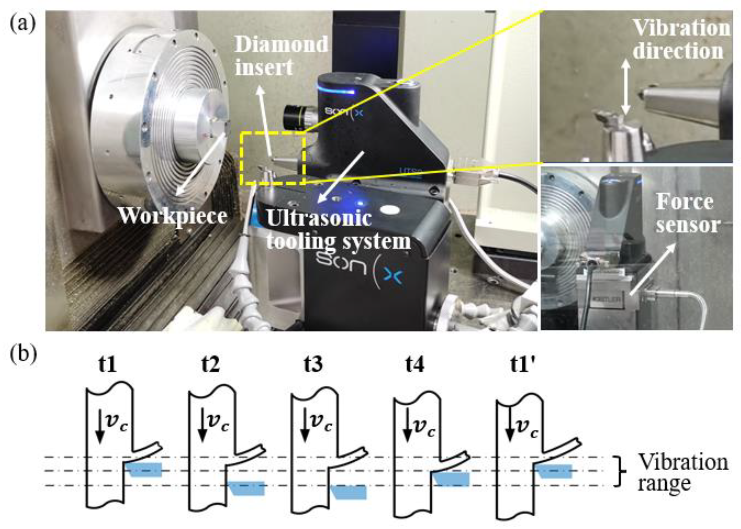
2.1. Theoretical Form Error Induced by Overcut of Vibration in HFUVAS

The target line is the theoretical tool path to cut the microlens array without consideration of the smoothing tool path in HFUVAS, which can be described by Equation (2):
z 0 y = y p 2 n 0.5 2 r + r 2 y p 2 n 0.5 2  
where n is the sequence number of the lenslet in the y direction, r is the lenslet radius. p 2 is the lenslet pitch in the y direction. During the HFUVAS process, the diamond tool is moved along the target profile. The tool tip without considering tool vibration is determined by Equation (3):
y 1 t = v c t z 1 t = z 0 y 1 t  
where t   is the cutting time, v c is the nominal cutting speed. In addition, the tool tip vibrates at a high-frequency vibration, which is assumed to be linear, and it can be determined by Equation (4):
y 2 t = A cos 2 π f t  
where f is vibration frequency and A is vibration amplitude. Then, the tool tip trajectory considering tool vibration can be determined by Equation (5):
y t = y 1 t + y 2 t z t = z 1 t  
When the tool decomposition speed in the y-axis direction is zero, the front-cut limit and back-cut limit of the tool track appear in each vibration cycle. As a result, they can be determined by solving Equation (6) as follows:
  y t = 0  
Based on Equations (2)–(6), the tool trajectory with the front-cut limit and back-cut limit in HFUVAS of a certain target profile can be obtained. Figure 2a presents the simulated cutting results in HFUVAS of the target profile of microlens array. The vibration frequency and vibration amplitudes are 104 kHz and 0.75 μm. The radius and pitch of the lenslet are 1 mm and 199.75 μm, with a lenslet depth of 5 μm. The back limit of the tool track forms a back-cut line to be left on the workpiece in a downhill line. By contrast, the front limit connects as a front-cut line to leave the workpiece in an uphill line. As a result, the cut line deviates from the target line, leading to a theoretical form error. It should be noted that as the slope angle of the target profile along the cutting direction increases, the theoretical form error also increases. For the target profile of the microlens array, the maximum form error arises at the edge between two adjacent lenslets, as shown in Figure 2b.

2.2. Theoretical Form Error Caused by Overcut of Tool Edge in HFUVAS

In diamond sculpturing of a microlens array, there exists a theoretical form error between the designed microlens array and the machined microlens array induced by overcutting of the tool edge. Take sculpturing of a single lenslet with an aperture of AC1EC2 as shown in Figure 3. When the diamond tool moves along the target line of ABCDE, the curvature radius of the lenslet contour perpendicular to the cutting direction increases to the largest at point C and then decreases. Since the tool radius keeps constant which is equal to the largest curvature radius at point C, the tool edge will overcut the material when the tool moves along line ABCDE except at the point of C. To be specific, at the position of point C, the lenslet contour perpendicular to the cutting direction is line C1CC2, whose curvature radius is equal to the tool radius. While at point D, the curvature radius of the lenslet contour, namely the radius of line D1DD2 as depicted on the blue circle is smaller than the tool radius, resulting in the tool edge overcutting the line D1DD2. As a result, overcut of the tool edge in HFUVAS leads to a deviation between the designed structure and the machined structure.
It is essential to generate the machined structured surface and identity the theoretical form error between the designed microlens array and the microlens array generated by tool edge sculpturing in order to evaluate the machining accuracy for this machining technique. In this process, two coordinate systems, namely the local tool coordinate system ( O t x t y t z t ) and the workpiece coordinate system ( O w x w y w z w ) are defined as depicted in Figure 4a. Considering the tool rake angle is 0°, tool edge in the local tool coordinate system is determined by Equation (7) [21]:
x t = R c o s θ t y t = 0 z t = R s i n θ t ,   θ t θ m i n , θ m a x  
where R is the tool nose radius. θ t represents the angular position of the point on the cutting edge, θ m i n and θ m a x are the minimum and maximum angle of the effective tool edge.
To generate the machined structure by tool sculpturing, the coordinates ( x t ,   y t , z t ) of all points with a certain sampling on the tool edge should be transformed as ( x t w ,   y t w ,   z t w ) in the workpiece coordinate system. The tool edge center is expected to be transformed to the original point O w of the workpiece coordinate system. The relationship between the workpiece coordinate and the local coordinate for the tool edge is given by Equation (8):
x t w y t w z t w 1 = 1   0   0   0   0   1   0   0     0   0   1   R     0   0   0   0   x t y t z t 1  
Coordinates of all the points on the tool edge in the workpiece coordinate system can be calculated by taking into account of the tool path, which is given by Equation (9):
x w = x t w + p 1 k n 1 / 2 y w = y t w + v c t z w = z t w + z p 1 k n 1 / 2 , v c t  
where p 1 is the pitch of lenslet in the feed distance, or the distance between two target lines, k n is the number of the target line ( k 1 = 1 ,   k 2 = 2 ,   k 3 = 3 as shown in Figure 4b). v c and t represent the tool’s normal cutting velocity and moving time at each target line. z p 1 k n 1 / 2 , v c t is the z coordinate value of the cutting point ( p 1 k n 1 / 2 , v c t ) in the workpiece coordinate system. By determining all the tool points with respect to target lines, surface generation of the microlens array machined by HFUVAS can be simulated and analyzed. Then, the theoretical form error between the designed microlens array and the machined microlens array can be obtained by subtracting the geometry of the designed microlens array from the geometry of the simulated microlens array.

3. Methods

3.1. Machining Parameters

Microlens array with 10 × 10 lenslets was machined. r and p were 1 mm and 199.75 μm, resulting in a lenslet depth d of 5 μm and a maximum cutting depth of 10 μm of the microlens array. Table 1 shows the machining parameters of the cutting experiments. To avoid tool interference with the workpiece, the tool radius must not be larger than the workpiece contour in the feed direction and the tool clearance angle must be larger than the maximum slope angle in the cutting direction in consideration of the fact that the tool rake angle is 0° so the rake face would not interfere with the workpiece. In this research, the tool radius is equal to the workpiece contour. The maximum slope angle of the target profile of the microlens array is 5.7°. As a result, a diamond tool with a rake angle of 0°, clearance angle of 15°, nose radius of 1 mm, tool edge radius of 50 nm, and arc waviness of fewer than 0.25 μm provided by Contour Fine tooling Ltd. was used in the experiment. Mirrax 40 steel was used as the workpiece material in this study. It is a remelted stainless steel pre-hardened to 40 HRC with excellent ductility, machinability, polishability, and toughness, which makes it appropriate for injection molds, flow molds and extrusion dies. The chemical composition of Mirrax 40 steel includes (wt.%): C: 0.21, Si: 0.9, Mn: 0.45, Cr: 13.5, Mo: 0.2, Ni: 0.6, V: 0.25.
Before the cutting experiment, it is necessary to analyze the theoretical form error of the microlens array to evaluate the machining feasibility. Figure 5a shows the theoretical form error induced by overcutting of vibration in HFUVAS of microlens array with 3 lenslets. The maximum form error arose at the edge of two adjacent lenslets and it is within 0.1 um. Figure 5b,c shows the form error induced by overcutting of tool edge in HFUVAS of microlens array with 3 × 3 lenslets. The maximum form error arose at the intersection cusp of four adjacent lenslets and it is only 0.025 um. These two form errors are relatively small and insignificant so the microlens array is machinable theoretically. It should be noted that the theoretical form error between the designed microlens array and the machined microlens array by HFUVAS could increase to an intolerable value for ultraprecision machining with increasing lenslet depth and decreasing lenslet radius. In the cutting experiment, the cutting depth was 1 μm larger than the structure depth to ensure the successful fabrication of the structure, which leads to a total cutting depth of 11 μm. To protect the cutting tool from damage and achieve a good surface finish, the microlens array was cut with four depth layers of 5 μm, 3 μm, 2 μm, and 1μm, respectively. It is important to note that to avoid overshoot and vibration of machine motion caused by a quick acceleration of the Z-axis slide arising at the sharp edge between lenslet, segment cutting was conducted, and each layer was machined by two steps for both CS and HFUVAS, as shown in Figure 5d. This tool path smoothing process would not affect the analyzing results of theoretical form error based on target lines as mentioned before because the cut lines left on the workpiece between the target line and the smoothed tool path are the same. After a list of lenslet was fabricated, the cutting tool was moved by a distance of p 1 in the x -axis to fabricate another list of lenslets. The coolant was clairsol 330/odorless kerosene and minimal quantity lubrication (MQL) method use applied. Quadrilateral microlens array was fabricated by means of conventional sculpturing and high-frequency vibration-assisted sculpturing, respectively, under the same tool path.

3.2. Experimental Setup

Figure 6 shows the experimental setup to conduct the HFUVAS and CS experiment of the quadrilateral microlens array. On the Moore Nanotech 350 FG machine from Nano-technology Inc. USA, an ultrasonic tooling system with an operating frequency of 104 kHz from Son-X GmbH Germany [22] was set up. The input current of UTS2, which was proportional to the vibration amplitude, was set as 30 mA with a corresponding amplitude of about 0.75 μm in the cutting direction. The workpiece material was Mirrax 40, which is remelted stainless steel used for precision injection molding and press molding. The workpiece was mounted on a fixture and then vacuumed on the spindle. A nominal cutting speed of 100 mm/min was used when the microlens array was manufactured, followed by a programmed position code. A sampling rate of 2.5 μm along the cutting direction was used to create the position code with respect to the target line. Using a white interferometer from Nexview, Zygo Ltd., the machined structures’ geometry form and surface roughness were assessed. The point data of the 3D structure was exported from the measured software and then reconstructed on the Matlab software for form accuracy analysis. The morphology and element analysis of the machined structure and the cutting tool was measured by a scanning electron microscope (SEM, TESCAN VEGA3) equipped with energy dispersive spectroscopy (EDS).

4. Results and Discussions

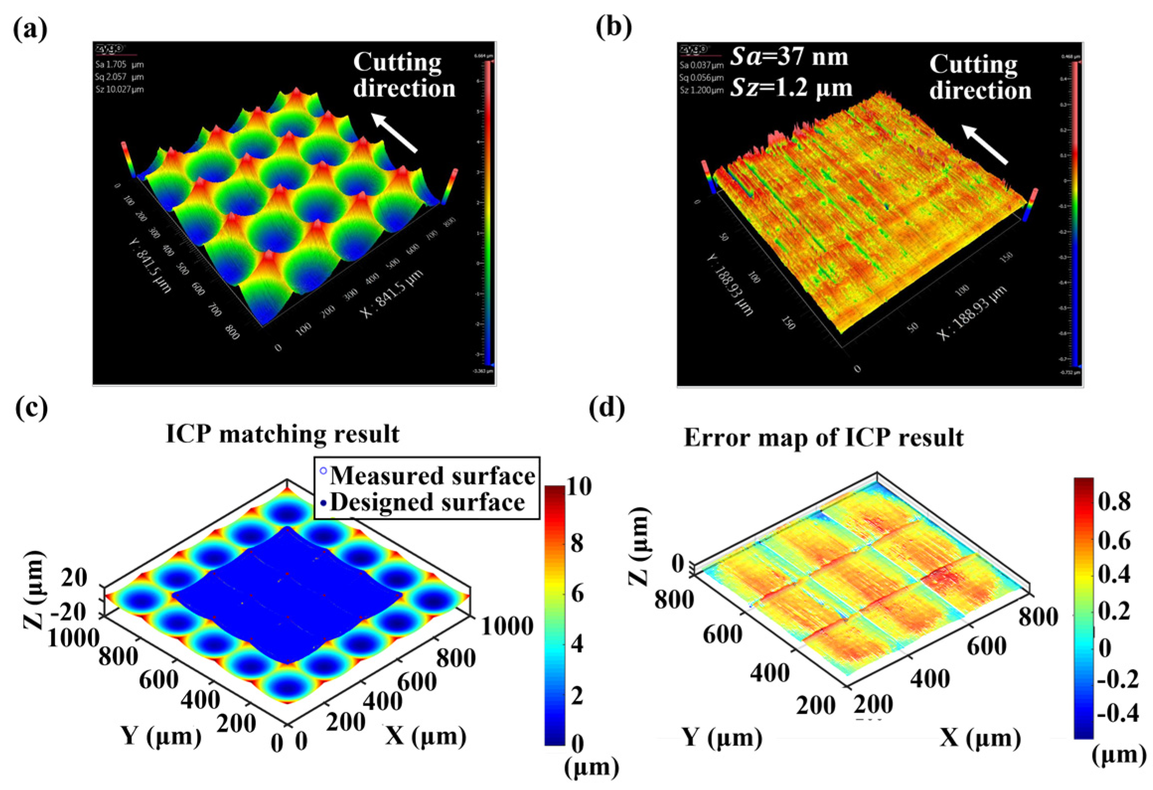
4.1. Form Accuracy Analysis of the Machined Microlens array

Figure 7a shows a figure of the microlens array machined by CS and HFUVAS. It can be seen that CS produced the microlens array with a poor and blurry structure surface while HFUVAS achieved a smooth and mirror surface finish. Figure 7b,c presents the measured 3D structure of the machined microlens array. The 2D profiles across the centers of lenslets along the feed direction (P1) and the cutting direction (P2) were measured and analyzed for further study.
Figure 8 shows the results of the form deviation between the designed profile and the measured profile for the microlens array machined by CS and HFUVAS. The results show that the measured profile of the microlens array machined by CS had a large deviation from the corresponding designed profile. The measured profiles were not smooth with surface variation as compared with the designed one. In contrast, for the form deviation between the target profile and the measured profile of the microlens array machined by HFUVAS, the measured profiles were smoother as compared with those machined by CS, and the form deviation between the measured profile and the designed profile is significantly reduced. As a result, it is found that HFUVAS can improve surface finish and reduce form deviation as compared with CS.
To further identify the form error of the machined profile. Figure 9 shows the form error between the designed profile and the measured profile for the microlens array machined by CS and HFUVAS. The form error included two parts: namely E1 and E2. E1 represents the form error induced by the machining of the profile apart from the sharp edge between the lenslets, and E2 represents the form error induced by the machining of the sharp edge between the lenslets (as marked with a red box). For form error of microlens array machined by CS, as shown in Figure 9a. E1 and E2 reached 0.5 μm and 0.3 μm, respectively, making the total form error of the machined microlens array intolerable for ultraprecision applications. For form error of microlens array machined by HFUVAS as presented in Figure 9b. E1 and E2 were close to 0.2 μm and 0.2 μm, respectively. The total form error of the machined microlens array was about 0.4 μm, which was reduced significantly compared with the result of CS. It seemed that the form error induced by the machining of the sharp edge between lenslets occupied quite a portion of the total form error and it could be associated with generation burrs or plastic deformation which will be analyzed in the SEM image of the machined microlens array surface morphology.

4.2. Surface Morphology Analysis of the Machined Microlens Array

Figure 10 shows the scanning electron microscopy (SEM) image of the surface morphology for the microlens array machined by CS and HFUVAS. In the CS, the machined surface was filled with scratching and micro-tearing morphology, which is the explanation for the surface variation of the measured profile. It is interesting to note that even the first lenslet at the beginning of machining exhibited such surface morphology, suggesting that tool wear was not the main reason for such poor surface quality. Workpiece material adhered to the diamond tool and then rowed and plowed the workpiece surface could be the reason for this morphology due to material affinity between carbon from the diamond tool and steel from the workpiece. Besides, because of material adhesion, the diamond tool could become blunt so the edge between lenslets was not sharp and was not distinguishable, resulting in a large form deviation at this edge. In view of the HFUVAS, the machined surface was smooth with apparent sharp edges between lenslets. However, there existed small burrs on the sharp edge, which could be caused by plastic deformation of the workpiece material and it is one of the major sources of the form error for the microlens array being machined by HFUVAS.
To validate the material adhesion conjecture for an explanation of the surface morphology of the machined structures, cutting tools after CS and HFUVAS of the microlens array were observed for analyzing the tool conditions. Figure 11a–d shows the SEM image and the energy dispersive spectrometer (EDS) analysis of the cutting tool after CS of the microlens array. Tool edge exhibited plenty of material adhesion of Cr and Fe and existed a considerable tool wear width. This indicated that during CS of the microlens array, material from the workpiece adhered to the cutting tool and worsen the machined surface quality. With increasing cutting distance, tool wears increased and then enhanced material adhesion, thereby further deteriorating the surface quality. For the cutting tool after HFUVAS of the microlens array as shown in Figure 11e,f, the cutting tool does not exhibit apparent material adhesion and tool wear. This leads to the conclusion that the improved surface quality of the microlens array machined by HFUVAS resulted from the reduction of tool wear and material adhesion due to the high-frequency intermittent cutting.

4.3. Technical Feasibility Analysis on HFUVAS of Quadrilateral Microlens Array

A high-quality machined structure with sub-micrometer form accuracy and nanometer-scale surface roughness is the premise of optical application. Obtaining the error map of the designed structure is a reasonable method to evaluate the form accuracy of a 3D structure. To investigate the technical feasibility of HFUVAS in the machining of the quadrilateral microlens array. Figure 12 and Figure 13 present the measured 3D structure, the surface morphology of a single lenslet after removing the structure form, the iterative closest point (ICP) matching result, and the obtained error map from matching for the 3 × 3 lenslets machined by CS and HFUVAS, respectively. The form accuracy and surface finish of the machined microlens array were significantly improved for HFUVAS compared with CS. Single lenslet machined by HFUVAS achieved an optical application level with a surface finish of 4 nm S a and a form error S z within 0.13 μm, compared with 37 nm and 1.2 μm obtained by CS correspondingly. The form error of 3 × 3 lenslets was much larger than that of the single lenslet, which could be more accurate and reliable to evaluate the form accuracy of a 3D structure. The form error of 3 × 3 lenslets machined by HFUVAS and CS were within 0.6 μm and 1.5 μm, respectively. The surface roughness and form accuracy of the microlens array machined by HFUVAS can meet the requirement of the optical application. This indicates that HFUVAS is a technically feasible method to fabricate 3D structures with a sharp edge on steel materials for molding of optical products.

5. Conclusions

This paper presents the investigation of a novel machining principle for high-frequency ultrasonic vibration-assisted sculpturing of the microlens array and then derives the theoretical form error between the designed microlens array and the machined microlens array. Following this, CS and HFUVAS of quadrilateral microlens array on steel were conducted for comparison. Then, the form accuracy and surface morphology of the machined structure as well as the tool wear were measured and then analyzed. Some findings are drawn as follows:
  • There is a theoretical form error between the designed microlens array and the machined microlens array in HFUVAS of microlens array due to overcutting the vibration and tool edge, which could increase with increasing lenslet depth or decreasing lenslet radius. As a result, this theoretical form error should be derived before machining to make sure that it is tolerable for ultraprecision machining.
  • CS-produced microlens array with poor form accuracy and surface finish caused by the coupling effect of material adhesion and tool wear. HFUVAS could significantly improve the form accuracy and surface quality compared with CS, achieving sub-micrometer form accuracy and surface roughness in the nanometer range due to the reduction of material adhesion and tool wear. This makes HFUVAS technically feasible in the effective fabrication of quadrilateral microlens arrays with sharp edges on steel for optical mold application.
Compared with segment diamond turning, the form error and surface roughness in diamond sculpturing could be increased to some extent. The generation of a small burr on the sharp edge in HFUVAS of the microlens array is one of the major sources of the form error. However, in our research, the surface roughness and form accuracy of the microlens array machined by HFUVAS could still meet the requirement of the optical application. Most importantly, the machining time can be reduced remarkably to improve machining efficiency.

Author Contributions

C.-F.C. and C.Z. conceived and designed the methodology and experiments; C.-F.C. and B.B. contributed to the materials and machining tools; C.Z. and X.L. performed the experiments; C.Z. analyzed the measurement data and wrote the draft on the technical content of the manuscript; C.-F.C. and X.L. reviewed and helped revise the content of the manuscript. All authors have read and agreed to the published version of the manuscript.

Funding

This research received no external funding.

Institutional Review Board Statement

Not applicable.

Informed Consent Statement

Not applicable.

Acknowledgments

The authors would like to express their sincere thanks for the financial support from the Research Office (project code: RK2Z) from The Hong Kong Polytechnic University. Special thanks are also due to the contract research project between the State Key Laboratory of Ultraprecision Machining Technology of The Hong Kong Polytechnic University and Son-X, Gmbh, Aachen, Germany.

Conflicts of Interest

The authors declare no conflict of interest.

References

  1. Fang, F.Z.; Zhang, X.D.; Hu, X.T. Cylindrical coordinate machining of optical freeform surfaces. Opt. Express 2008, 16, 7323–7329. [Google Scholar] [CrossRef] [PubMed]
  2. Zhu, Z.; To, S. Adaptive tool servo diamond turning for enhancing machining efficiency and surface quality of freeform optics. Opt. Express 2015, 23, 20234–20248. [Google Scholar] [CrossRef] [PubMed]
  3. Kong, L.B.; Cheung, C.F.; To, S.; Lee, W.B. An investigation into surface generation in ultra-precision raster milling. J. Mater. Process. Technol. 2009, 209, 4178–4185. [Google Scholar] [CrossRef]
  4. Paul, E.; Evans Chris, J.; Mangamelli, A.; McGlauflin, M.L.; Polvani, R.S. Chemical aspects of tool wear in single point diamond turning. Precis. Eng. 1996, 18, 4–19. [Google Scholar] [CrossRef]
  5. Shamoto, E.; Moriwaki, T. Ultaprecision Diamond Cutting of Hardened Steel by Applying Elliptical Vibration Cutting. CIRP Ann. Manuf. Technol. 1999, 48, 441–444. [Google Scholar] [CrossRef]
  6. Suzuki, N.; Haritani, M.; Yang, J.; Hino, R.; Shamoto, E. Elliptical Vibration Cutting of Tungsten Alloy Molds for Optical Glass Parts. CIRP Ann. Manuf. Technol. 2007, 56, 127–130. [Google Scholar] [CrossRef]
  7. Zhang, X.; Senthil Kumar, A.; Rahman, M.; Nath, C.; Liu, K. Experimental study on ultrasonic elliptical vibration cutting of hardened steel using PCD tools. J. Mater. Process. Technol. 2011, 211, 1701–1709. [Google Scholar] [CrossRef]
  8. Moriwaki, T.; Shamoto, E. Ultraprecision Diamond Turning of Stainless Steel by Applying Ultrasonic Vibration. CIRP Ann-Manuf. Technol. 1991, 40, 559–562. [Google Scholar] [CrossRef]
  9. Suzuki, N.; Yokoi, H.; Shamoto, E. Micro/nano sculpturing of hardened steel by controlling vibration amplitude in elliptical vibration cutting. Precis. Eng. 2011, 35, 44–50. [Google Scholar] [CrossRef]
  10. Zhang, J.; Suzuki, N.; Wang, Y.; Shamoto, E. Ultra-precision nano-structure fabrication by amplitude control sculpturing method in elliptical vibration cutting. Precis. Eng. 2015, 39, 86–99. [Google Scholar] [CrossRef]
  11. Zhou, X.; Zuo, C.; Liu, Q.; Lin, J. Surface generation of freeform surfaces in diamond turning by applying double-frequency elliptical vibration cutting. Int. J. Mach. Tools Manuf. 2016, 104, 45–57. [Google Scholar] [CrossRef]
  12. Yuan, Y.; Zhang, D.; Jing, X.; Ehmann, K.F. Freeform surface fabrication on hardened steel by double frequency vibration cutting. J. Mater. Process. Technol. 2020, 275, 116369. [Google Scholar] [CrossRef]
  13. Kurniawan, R.; Kiswanto, G.; Ko, T.J. Surface roughness of two-frequency elliptical vibration texturing (TFEVT) method for micro-dimple pattern process. Int. J. Mach. Tools Manuf. 2017, 116, 77–95. [Google Scholar] [CrossRef]
  14. Xing, Y.; Li, C.; Liu, Y.; Yang, C.; Xue, C. Fabrication of high-precision freeform surface on die steel by ultrasonic-assisted slow tool servo. Opt. Express 2021, 29, 3708–3723. [Google Scholar] [CrossRef] [PubMed]
  15. Zhang, L.; Hashimoto, T.; Yan, J. Machinability exploration for high-entropy alloy FeCrCoMnNi by ultrasonic vibration-assisted diamond turning. CIRP Ann. Manuf. Technol. 2021, 70, 37–40. [Google Scholar] [CrossRef]
  16. Mukaida, M.; Yan, J. Fabrication of Hexagonal Microlens Arrays on Single-Crystal Silicon Using the Tool-Servo Driven Segment Turning Method. Micromachines 2017, 8, 323. [Google Scholar] [CrossRef] [Green Version]
  17. Yuan, W.; Cheung, C.F. Theoretical and experimental investigation of the tool indentation effect in ultra-precision tool- servo-based diamond cutting of optical microstructured surfaces. Opt. Express 2021, 29, 39284–39303. [Google Scholar] [CrossRef]
  18. Li, L.; Yang, G.; Lee, W.B.; Ng, M.C.; Chan, K.L. Carbide-bonded graphene-based Joule heating for embossing fine microstructures on optical glass. Appl. Surf. Sci. 2020, 500, 144004. [Google Scholar] [CrossRef]
  19. Chi, Y.; Dai, W.; Lu, Z.; Wang, M.; Zhao, Y. Real-Time Estimation for Cutting Tool Wear Based on Modal Analysis of Monitored Signals. Appl. Sci. 2018, 8, 708. [Google Scholar] [CrossRef] [Green Version]
  20. Lin, Y.-C.; Wu, K.-D.; Shih, W.-C.; Hsu, P.-K.; Hung, J.-P. Prediction of Surface Roughness Based on Cutting Parameters and Machining Vibration in End Milling Using Regression Method and Artificial Neural Network. Appl. Sci. 2020, 10, 3941. [Google Scholar] [CrossRef]
  21. Zhu, W.-L.; Duan, F.; Zhang, X.; Zhu, Z.; Ju, B.-F. A new diamond machining approach for extendable fabrication of micro-freeform lens array. Int. J. Mach. Tools Manuf. 2018, 124, 134–148. [Google Scholar] [CrossRef]
  22. Gaidys, R.; Dambon, O.; Ostasevicius, V.; Dicke, C.; Narijauskaite, B. Ultrasonic tooling system design and development for single point diamond turning (SPDT) of ferrous metals. Int. J. Adv. Manuf. Technol. 2017, 93, 2841–2854. [Google Scholar] [CrossRef]
Figure 1. Configuration of the cutting systems and tool paths of microlens array for: (a) diamond turning and (b) diamond sculpturing.
Applsci 12 10937 g001
Figure 2. (a) Tool trajectory in HFUVAS of the target line of microlens array, (b) a comparison of the target line and cut line, with r of 1 mm and p 2 of 199.75 μm.
Applsci 12 10937 g002
Figure 3. A schematic diagram of diamond sculpturing of microlens array.
Applsci 12 10937 g003
Figure 4. Definition of coordinate system for sculpturing of microlens array: (a) view in the y w O w z w plane, (b) view in the x w O w y plane.
Applsci 12 10937 g004
Figure 5. Theoretical form error in HFUVAS of microlens array induced: (a) by overcut of vibration, (b,c) by overcut of tool edge, (d) smooth tool path generation of the target line.
Applsci 12 10937 g005
Figure 6. (a) A photo of the experimental setup, (b) a schematic of tool motion in HFUVAS.
Applsci 12 10937 g006
Figure 7. (a) A photo of the microlens array machined by CS and HFUVAS, (b,c) measured 3D structure of the machined microlens array.
Applsci 12 10937 g007
Figure 8. Form deviation analysis (Blue: designed profile; red: measured profile): (a) P1, (b) P2, for the microlens array machined by CS, (c) P1, (d) P2 for the microlens array machined by HFUVAS.
Applsci 12 10937 g008
Figure 9. Form error between the designed profile and the measured profile: (a) P1, P2 for the microlens array machined by CS, (b) P1, P2 for the microlens array machined by HFUVAS.
Applsci 12 10937 g009
Figure 10. SEM of the surface morphology for the microlens array machined by: (a) CS, (b) HFUVAS.
Applsci 12 10937 g010
Figure 11. (a,b): SEM of the cutting tool after CS of the microlens array, (c,d): EDS analysis results of (b,e,f): SEM of the cutting tool after HFUVAS of the microlens array.
Applsci 12 10937 g011
Figure 12. An analysis of surface quality and form accuracy of the microlens array machined by CS: (a) Measured 3D structure, (b) surface morphology of a single lenslet after removing the 3D form, (c) ICP match result of the measured structure and the designed structure; (d) error map obtained from the ICP result.
Applsci 12 10937 g012
Figure 13. An analysis of surface quality and form accuracy of the microlens array machined by HFUVAS: (a) measured 3D structure, (b) surface morphology of a single lenslet after removing the 3D form, (c) ICP match result of the measured structure and the designed structure; (d) error map obtained from the ICP result.
Applsci 12 10937 g013
Table 1. The machining parameters of the cutting experiments.
Machining ParametersCSHFUVAS
Diamond tool 1 mm tool nose radius, 0° rake angle, 15° clearance angle, 50 nm tool edge radius, less than 0.25 μm arc waviness
Workpiece materialMirrax 40 steel
Depth of cut (μm)5, 3, 2, 1
Nominal cutting speed (mm/min)100
Tool path generationSegment cutting with smooth tool path
LubricantCoolant (Clairsol 330/odourless kerosene, MQL)
Vibration frequency (kHz)No104
Vibration amplitude (μm)No0.75
Publisher’s Note: MDPI stays neutral with regard to jurisdictional claims in published maps and institutional affiliations.

