1. Introduction
In recent years, there has been a surge of interest in flexible-joint robots with inherent adaptations. Unlike rigid robots, the drive joints of flexible-joint robots have elastic elements between the motor side and the link side, introducing low output impedance, force sensing, passive mechanical energy storage, and increasing peak output power [
1,
2,
3]. In addition, the inherent flexibility of the elastomer can soften the impact, protect the drive mechanism, and improve the safety of human–machine interaction. Because of these characteristics, flexible-joint robots are widely used in the field of force control, such as exoskeleton robots, industrial flexible machining and assembly, medical surgery, etc., which physically interact with their surroundings [
4,
5,
6,
7].
The force control of a series elastic actuator (SEA) relies on accurate force estimation, dynamic modeling and contact force control, etc. The most direct method to measure the external torque is to mount force/torque sensors in robot joints or on the robot surface. However, there are many obvious drawbacks to this simple method [
8,
9]. For example, the precise installation of sensors increases the mechanical, electrical and software design complexity of the entire robot equipment and increases the cost of robot design and assembly. Additionally, the position where the force acts becomes limited, which limits the robot’s use conditions, making it difficult to apply universally to different types of robots. In addition, the force output signal needs to be filtered and amplified to be transformed into recognizable digital signals, and there are many uncertain perturbations and environmental changes (such as environmental temperature change and external electromagnetic interference), which may affect the accuracy and reliability and even seriously affect the normal operation of the force sensor.
Most of the robot external force-estimation studies are achieved indirectly by obtaining robot state information, including angle, angular velocity, and angular acceleration, combined with a dynamics model [
10,
11,
12]. Since robotic arm joint acceleration is usually not available by direct measurement and the acceleration signal obtained by direct discrete quadratic differentiation of the joint angle may be entrained with uncertain perturbations, conventional methods usually use different techniques to avoid the direct use of the acceleration signal [
13,
14,
15]. De Luca et al. [
16] proposed a method based on generalized momentum, which avoids the use of joint acceleration in their research on detecting and isolating robot executive structural faults. In addition, this method is widely used in robot external force estimation [
17,
18]. Furthermore, to avoid direct acquisition of the robot joint acceleration, Ohnishi et al. used the method of constructing the dynamic model in the mathematical form of the Laplace domain to estimate the external torque for the force control feedback loop [
19,
20].
With the further study of accelerometer angular velocity measurement [
21], the method of accelerometer direct measurement of the angular acceleration of the joint is introduced into the robot control process [
22,
23]. Hu et al. [
24] and Cheng et al. [
25] obtained the required system information by changing the sensor position and deriving the mathematical model.
In terms of SEA force control, Spong and other scholars have proposed a linear simplified model of flexible-joint robots, and various control methods based on this simplified model have been proposed [
10]. Tomei successively proposed a PD controller and gravity compensation control schema, and proved that the closed-loop stability condition is that the differential term is positive. Japanese scholars have made great contributions to flexible joint and servo control. Robotics represented by Ohishi proposed interference observer and vibration reduction ratio control, which have had great influence [
19,
20]. Among them, the interference observer is very effective in compensating the side friction of the motor, and has become the standard algorithm of servo motors and industrial machine manual control loops. Vibration reduction ratio control is divided into position mode and force mode. Other scholars have proposed control methods based on extended state observer (ESO) and feedback linearization [
12].
The proposed method’s significant contributions are as follows:
- (1)
The estimation of joint external torque based on a dynamic model is affected by friction and nonlinear factors, and it is difficult to model the motor side accurately. This paper proposes a strategy to independently identify the dynamic parameters of the elastic-joint robot’s motor side and the link side.
- (2)
The traditional method of obtaining contact force is based on RTOB or direct calculation. The former performs low-pass filtering on the acceleration signal, and the latter directly ignores the acceleration, which causes delay and error in force estimation. To solve this problem, we introduced an accelerometer and designed an extended Kalman filter (EKF) to obtain an acceleration signal with good real-time performance and a low signal-to-noise ratio, therefore improving the estimation of contact force.
- (3)
Aiming to solve the problems of poor control performance and mechanical resonance on the link side caused by the high-order dynamic characteristics of SEA, we propose that the vibration control method eliminates the overshoot and vibration in the transient process of force control.
2. Dynamic Parameter Identification
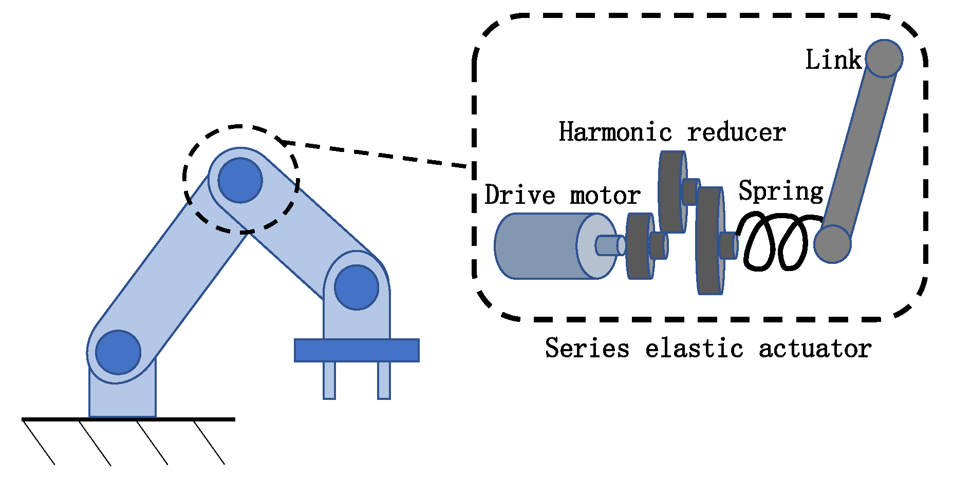
The elastic-joint robot driven by the SEA is shown in
Figure 1. The SEA consists of a drive motor, a harmonic reducer, a torsion spring, and a link. The harmonic reducer amplifies the torque generated by the rotation of the motor shaft. The amplified torque acts on the torsion spring to deform the torsion spring, causing a difference in rotation angle on both sides of the torsion spring (motor side and link side), and then transmits the torque to the link, driving the link to move.
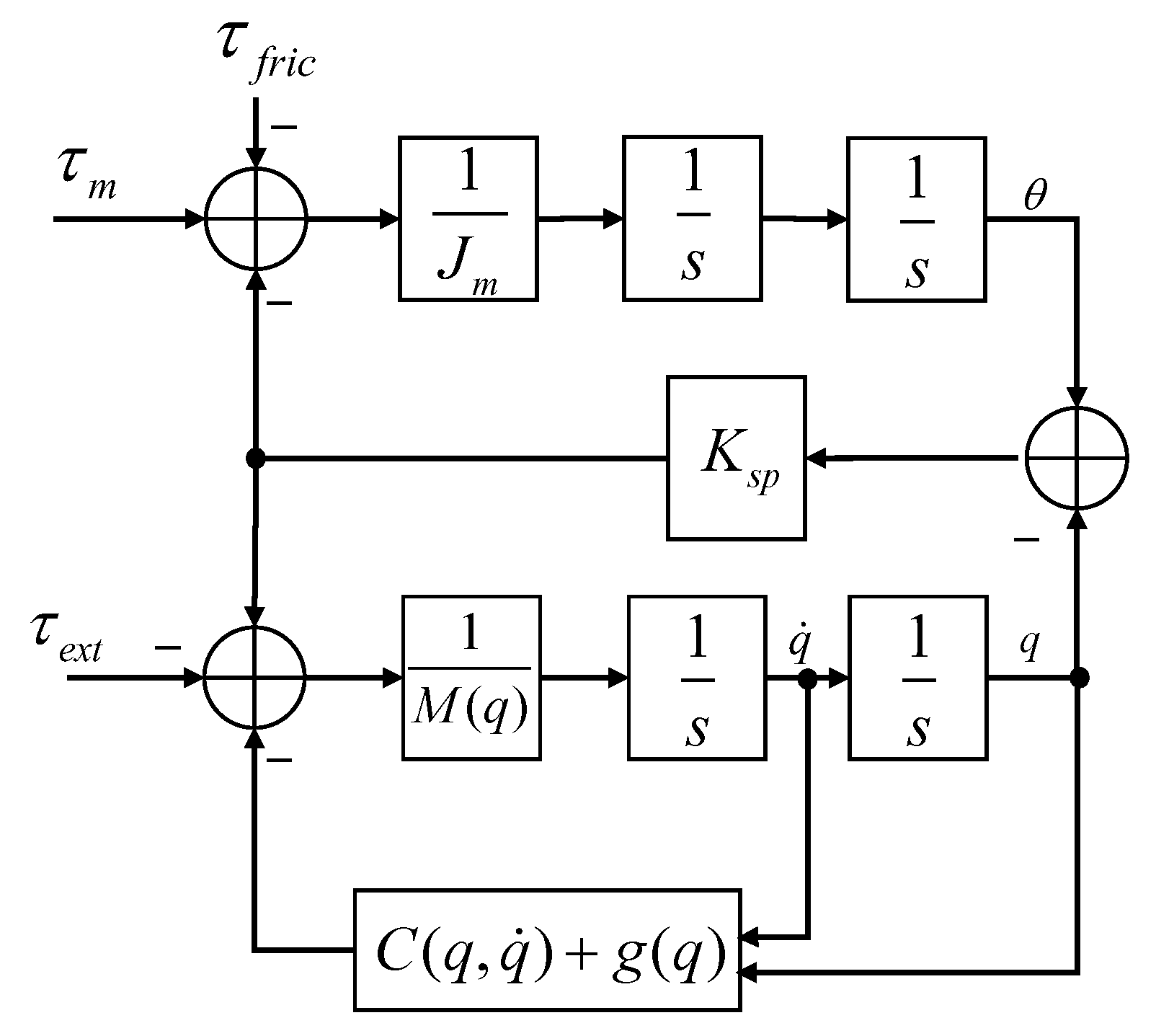
The dynamic model of a flexible robot with series elastic actuators as driving joints is shown in
Figure 2. The equations of motion for this model are
where
denotes the inertia matrix,
denotes the centripetal and Coriolis matrix and
denotes the gravity vector.
and
q are, respectively, the motor and link angles.
and
are the external torque applied to the robot link and the torque applied by the elastic-joint deformation, respectively.
and
denotes motor torque acting on the motor inertia
and friction torque.
denotes the Hooke coefficient of the torsion spring in the joint of the series elastic actuator.
For the elastic single-joint robot system, the equations of the link side and the motor side using Equations (1) and (2) are as follows:
where the friction model adopts the most widely used Coulomb-viscous model,
is the viscous friction coefficient,
is the Coulomb friction coefficient,
is the inertia of the link, and
and
are the gravity component of the link.
Since there is motor friction in the dynamic model on the motor side and about a quarter of the motor output torque is used to overcome the effects of various frictions, motor friction becomes the most significant factor affecting the accuracy of the dynamic model. To reduce the influence of the friction model parameters on the motor side and obtain more accurate dynamic model parameters on the link side, this paper adopts the strategy of independent identification of the dynamic model on the motor side and the link side. The elastic coefficient of the torsion spring and the dynamic model parameters of the elastic-joint robot are identified, respectively, by the system identification method based on model parameters.
The bridge connecting the dynamic model of the motor side and the dynamic model of the link side of the elastic-joint robot driven by the series elastic drive is the torque generated by the deformation of the elastic element. Therefore, the elastic element’s mathematical model and model parameters are first studied.
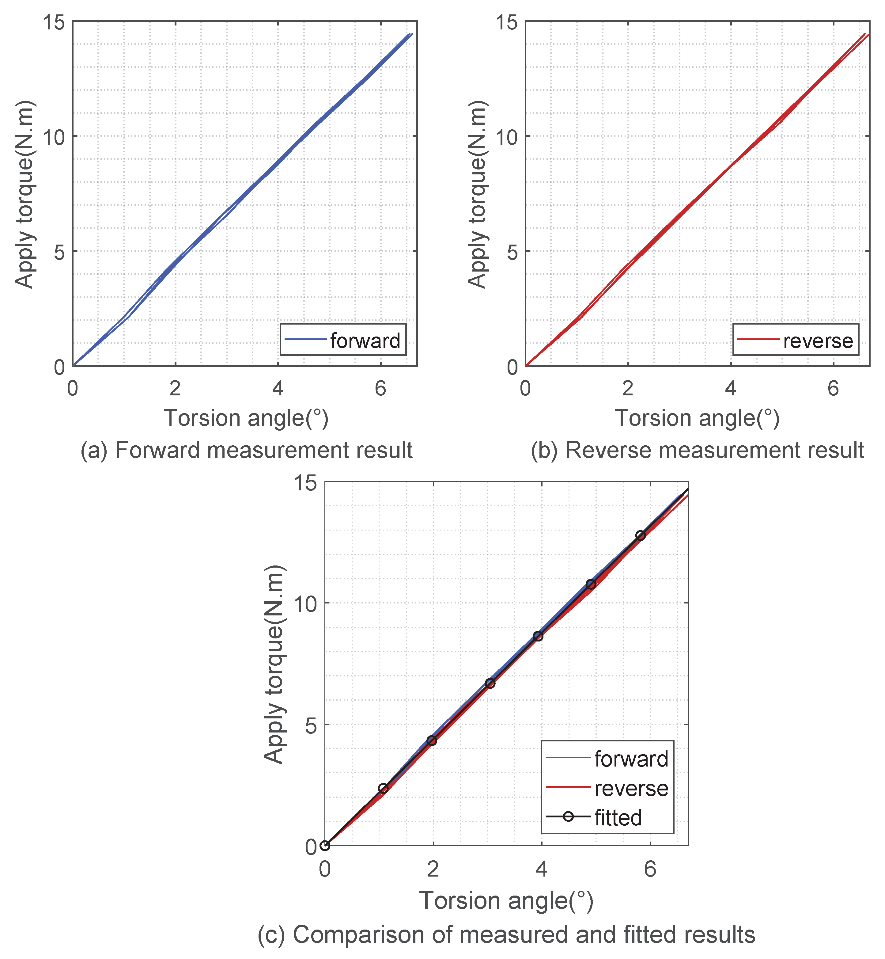
By applying torques in different directions and sizes to the link rod, measuring the torsion angle (the difference between the motor angle and the link rod angle), repeating the experiment many times and recording the data, the stiffness curve of the elastic body is obtained, as shown in
Figure 3.
It can be seen from the figure that the torsion angle of the elastic body has an excellent linear correspondence with the output torque. Therefore, according to Hooke’s law (3), using the least-squares parameter estimation identification in the previous section, it can be calculated that the elastic stiffness of the elastic body is 2.2 N·m/degree.
We linearly parameterize the dynamic Equations (4) and (5) of the elastic single-joint robot, and obtain
A linear parametric form that satisfies the linear least-squares estimation method
During the parameter-identification process, the sensor collects the angles q and between the link rod side and the motor side, and the data matrix is obtained. Combined with the elastic coefficient obtained from the separate identification, the elastic force of the elastic element during the movement can be calculated. Since the link rod side is not affected by the interaction force of the external environment during the whole identification process, the right side of the equation only has the elastic force of the elastic deformation of the spring. The driving torque of the motor is obtained through the torque signal of the current feedback. According to the principle of least-squares parameter estimation, the linear parameter equation requires that cannot be a singular matrix. By designing the excitation trajectory to ensure that the data matrix can fully stimulate the parameters to be identified, more accurate dynamic model parameters can be obtained.
This paper uses the fmincon function in Matlab to solve the optimization problem. This function uses optimization methods such as the interior point method and sequential quadratic programming algorithm to realize parameter optimization under equality and inequality constraints. In addition, it is widely used in solving optimization problems because of its versatility.
3. External Torque Estimation and State Information Acquisition of Robot Link Side
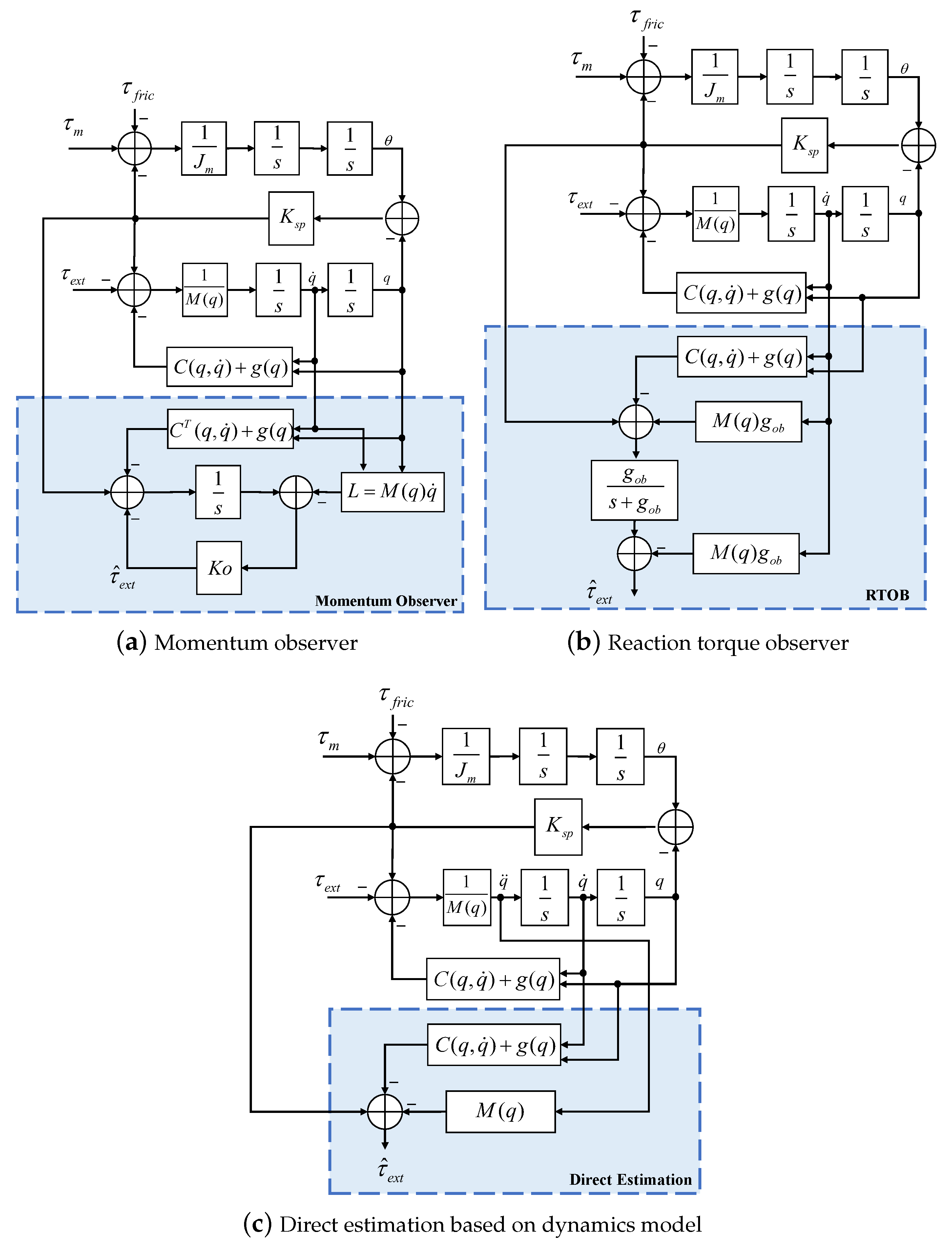
Photoelectric encoders are installed at both ends of the serial elastic driver (motor side and link side) to collect position information, so the driving torque of the link can be calculated by the deformation of the torsion spring. In this paper, three external force/torque estimation methods are used for comparison. The first method observes the real-time change of the robot’s momentum, as shown in
Figure 4a. The second method observes the reaction torque, as shown in
Figure 4b, which is mainly obtained by observing the driving torque and angular velocity, which avoids the requirement of angular acceleration in the dynamic equation. The third method is direct estimation based on the dynamics model.
3.1. Dynamics Model-Based Direct Estimation (DE)
Based on the system dynamics model, external force is directly calculated from the dynamics Equation (
1) of the link side of the robot, as shown in
Figure 4c.
The robot’s driving torque and real-time joint angle need to be observed in these three force-estimation methods. The difference is that MOB and RTOB only need to observe the real-time angular velocity of the link side, while DM needs to obtain real-time angular acceleration.
3.2. Link-Side State Information Acquisition
In the traditional robot control system, the angle of the robot SEA joint is collected by adding photoelectric encoders at two ends of the joint. To obtain the link-side angular velocity and angular acceleration , the first and second differential of the angle returned by the photoelectric encoder will amplify the quantization noise of the sensor and make the signal unusable. Therefore, differential results are generally filtered, but the introduction of filtering will lead to the delay of the robot link state information while filtering out sensor measurement noise and reducing the real-time and even the stability of the control system.
To obtain the angular acceleration signal of the link, accelerometers are mounted on each link of the robot. Angular acceleration is obtained by fusing the linear acceleration signal returned by the accelerometer and the position signal produced by the photoelectric encoder with the EKF.
3.3. Accelerometer Initial Pose Calibration
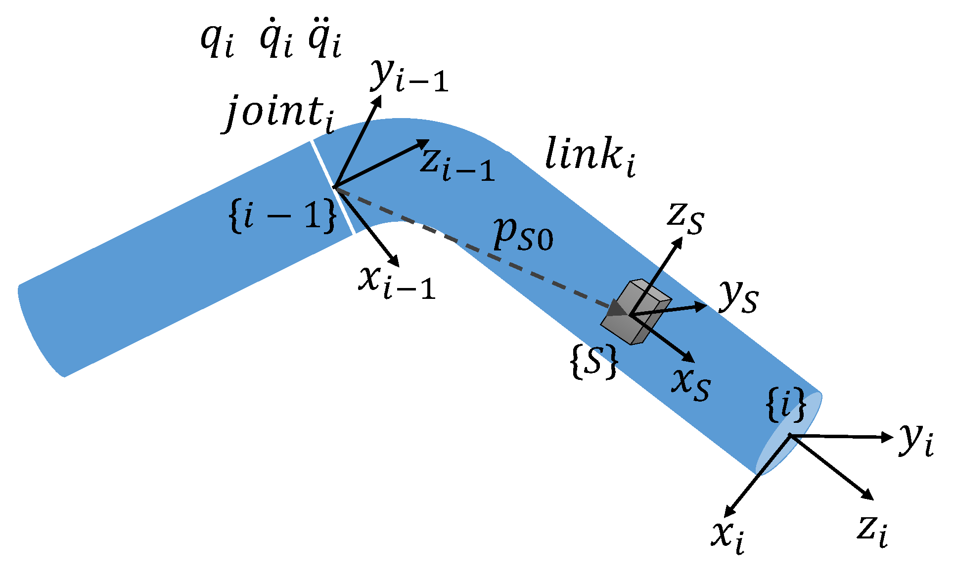
After the accelerometer is installed on the link i, the initial relative position
and the orientation
between the accelerometer and joint i need to be determined. In the robot control system, the standard DH modeling method is adopted; i.e., the last joint of the link is taken as its fixed coordinate frame, as shown in
Figure 5.
The initial relative position and the orientation mentioned above can use four parameters
to describe, as follows:
where
The robot in this paper is a joint-type robot, and the analysis of the translational joint is similar. The linear velocity of the sensor caused by the rotation of joint i can be expressed as
Furthermore, taking the derivative of Equation (
11), the linear acceleration of the sensor
caused by the rotation of joint i can be expressed as
Let and represent the orientation from the world frame {w} to the fixed frame {i − 1} of joint i. In the calibration process, only the current joint i is rotated and the other joints are in the zero position, so .
In addition, the frame {i − 1} is fixed with respect to the world frame {w} during calibration. The accelerometer frame {S} is affected by joint rotation
. Considering the effect of the acceleration of gravity
, the deviation of the accelerometer and the conversion relationship between reference frame, the linear acceleration relative to the accelerometer frame can be written as
where
and
and can be obtained by offline processing of angle collected from the encoder, which are used as input data for calibration parameter identification, and three-dimension linear acceleration obtained from the accelerometer is used as output data. The identification algorithm can obtain the accelerometer sensor’s initial position and orientation relative to the joint frame {i − 1}, including seven parameters.
3.4. Extended Kalman Filter-Based System-State Acquisition
Because of various uncertainty factors in the system, such as imperfect mathematical models, difficulty of control, model system disturbance, sensor measurement noise, etc., the state of the system is often inaccurate. The Kalman filter algorithm solves this problem effectively and is widely used in motion-control systems. The Kalman filter algorithm can estimate the process state of the system effectively by minimizing the squared mean of errors. It can effectively filter out the noise of measurement systems, correct the state of the system and reduce the influence of system uncertainty.
The dynamic state model of the system is
To improve the result of state estimation, the measurement equation combines the measurement values of the photoelectric encoder and the accelerometer. We note the system variable as
. The system measurement model is
where
w and
v are system process noise and measurement noise, respectively.
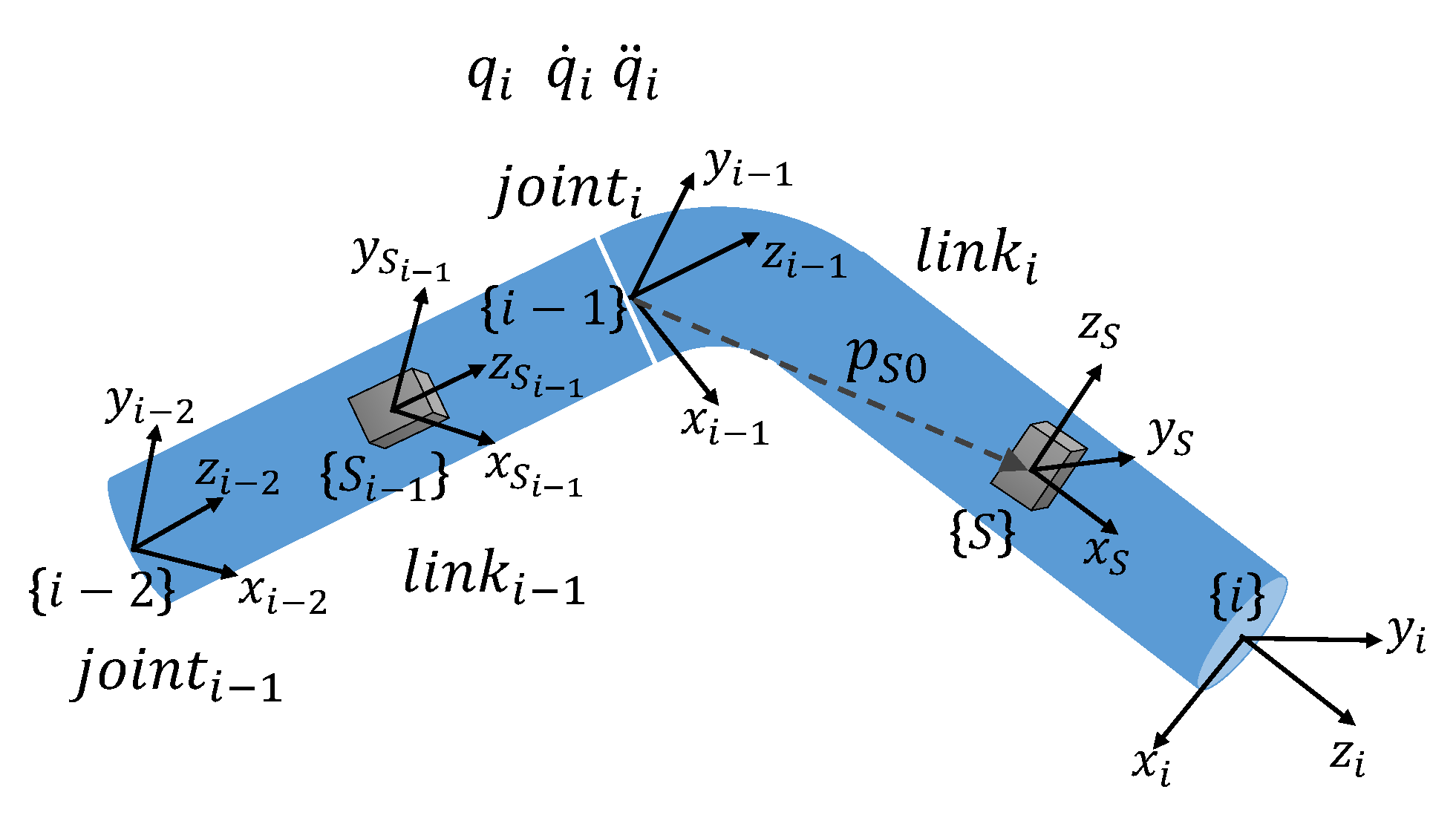
is a nonlinear relationship
, as shown in
Figure 6.
The linear acceleration directly returned from the accelerometer is relative to the frame , and can be converted to the fixed frame {i − 1} of the joint i through the relationship .
can be split into centripetal acceleration, centrifugal acceleration caused by the rotation of joint i, and linear acceleration synthesized by previous joint motion
(which includes gravitational acceleration).
Linear acceleration
is the representation on the frame {i} of the linear acceleration synthesized from link 0 to link i − 1 during the movement process, which can be obtained by converting the measurement result returned by the accelerometer fixed on the link i − 1 to the coordinate system {i − 1}, as follows.
where
and
are the relationships determined by the robot positive kinematics.
and
are position and orientation determined by the accelerometer calibration.
are obtained by recursive transfer between the mutually connected links.
The general form of KF is suitable for the linearity of the system state equation and measurement equation. Due to the nonlinearity of the system measurement equation in this paper, the EKF is used for sensor-data fusion.
The system state model (14) and measurement model (15) are continuous-time models, while the control system is in discrete form, so it is discretized using the ZOH (Zero-Order Hold) method. The sampling time is supposed to be
.
where
Expand the nonlinear
at the prior estimate
to obtain the linear form
where
Both the system state equation and the measurement equation are in linear form, and the Kalman filter method can be used for sensor-data fusion processing. EKF estimates the system state in an iterative form through two steps of prediction and correction, as
Figure 7 shows. In the prediction stage, the prior estimate of the system state at the current moment is calculated according to the system state at the previous moment; at the same time, the prior estimate of the error covariance matrix of the variance between the prior estimate and the posterior estimate
of the system state is calculated. In the correction stage, the Kalman filter gain
is calculated to minimize the error covariance matrix. Then, using the Kalman filter gain, the measurement results are fed back into the prior estimate to obtain the corrected system state estimate (a posteriori estimate), and the error covariance matrix is updated. The matrix
R and the matrix
Q are the covariance matrices of measurement noise and system noise, respectively, which are defined as follows:
4. Torque Control and Vibration Reduction of Elastic-Joint Robot Research
According to the method of separately identifying the dynamics of the link side and the motor side of the elastic-joint robot, the accurate dynamic parameters of the link side are obtained, but the dynamic model obtained by the identification of the motor side has great uncertainties. Such model uncertainties include friction models that are difficult to model accurately. To offset the negative effects of various disturbances on the motor-side model, the disturbance observer is used to estimate the disturbance. The equivalent disturbance is used as the feedback inner loop to compensate so that the motor-side model is equivalent to an ideal torque source. The advantage of this is to simplify the design and control of the outer loop of the system design and effectively improve the system’s robustness.
The flexibility of the series elastic actuator leads to the generation of mechanical natural frequency vibrations. This feature has a great impact on the force control of the robot end. Therefore, under the premise that the anti-disturbance motor side is used as the ideal torque source, the force control of the link is realized by adding resonance proportional control. At the same time, the vibration characteristics of elastic joints are analyzed and studied, and appropriate suppression strategies are adopted.
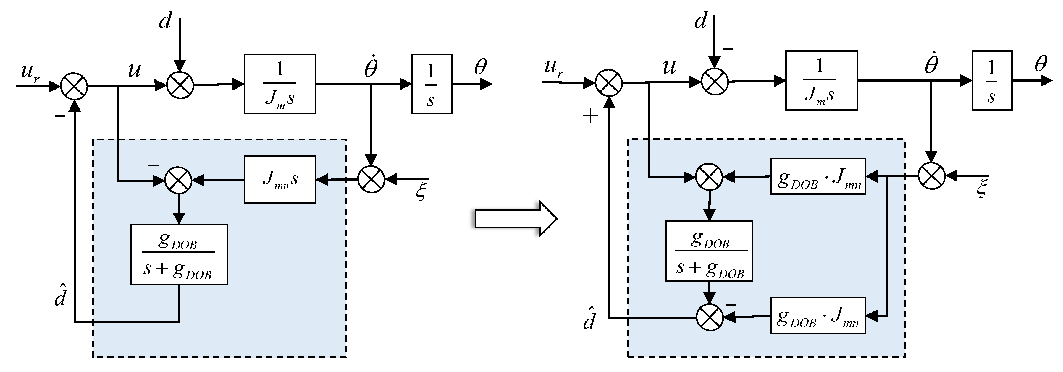
4.1. Disturbance Observer Based on Motor-Side Model
Due to considerable uncertainty in the dynamic model obtained by motor-side identification, feedback control based on the disturbance observer is adopted [
26]. The purpose of applying it to the motor side of the elastic-joint robot is to compensate for the model uncertainty and motor friction disturbances caused by inaccurate identification, as shown in
Figure 8.
4.2. Link-Side Acceleration Estimation Based Force Control
Due to joint elasticity, there will be obvious vibration in the control system output. The vibration frequency is equal to the anti-resonance frequency of the elastic joint. We introduce the resonance proportional coefficient to adjust the resonance frequency and anti-resonance frequency ratio, and adjust the controller coefficients to configure the poles of the closed-loop system can realize the stable force control of the elastic-joint robot.
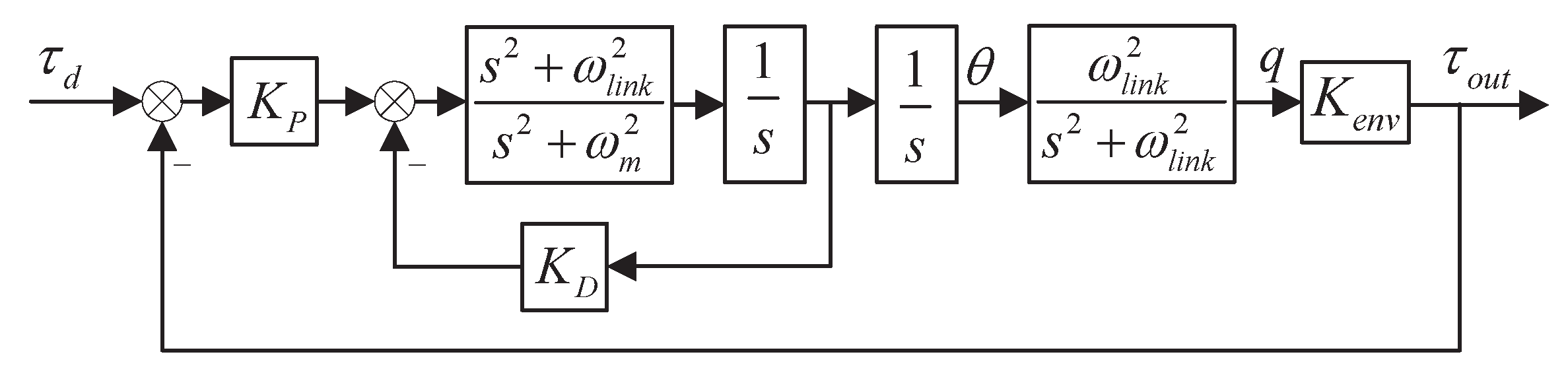
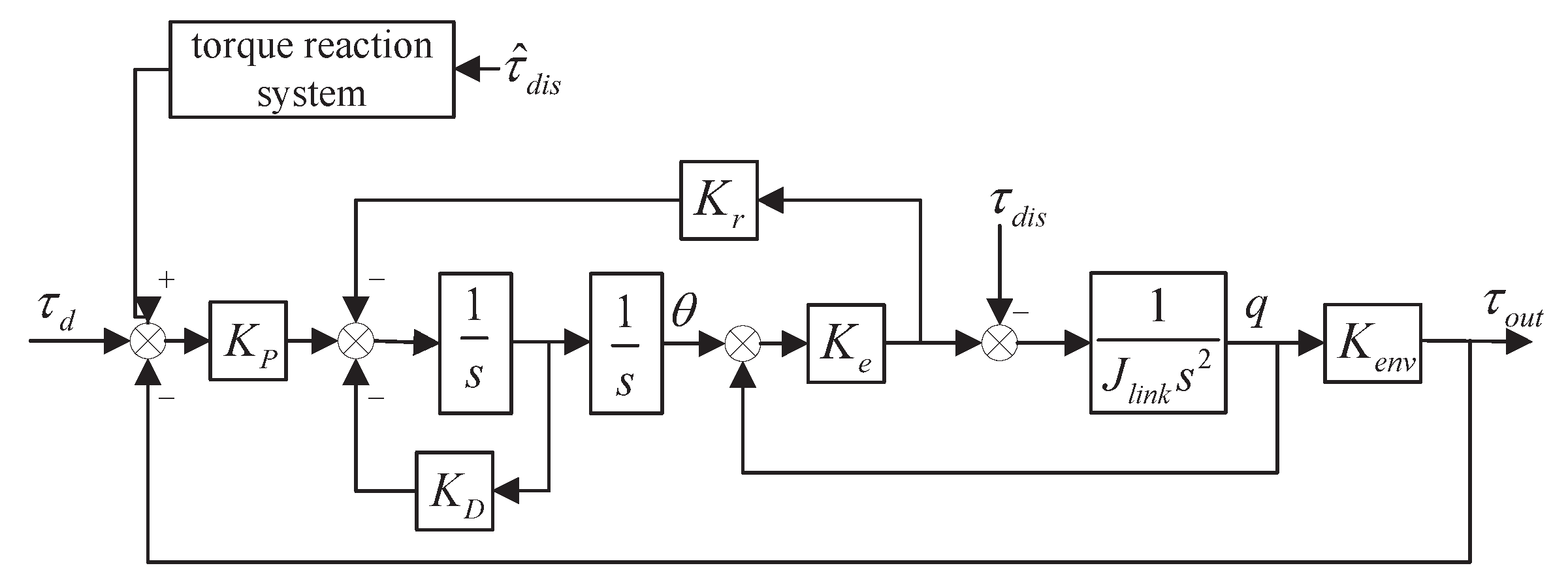
4.2.1. Vibration Suppression-Based Force Control
As shown in
Figure 9, resonant proportional feedback control is used for the system with added spring feedback gain. At the same time, the interaction between the link and the environment is modeled as a spring with stiffness
. Adjusting the resonance proportional gain
to change the proportional relationship between the resonance frequency and the anti-resonance frequency is helpful to configure the poles of the closed-loop feedback control system.
and
are the proportional gain and differential gain, respectively. By selecting the appropriate control gain, the controller can be adjusted to make the system meet the design system performance index.
In this closed-loop feedback control system, the transfer function from the reference input torque to the output torque is
According to the system transfer function, the system has fourth-order characteristics. Let all poles of the closed-loop system be equal to the anti-resonance frequency
, i.e.,
therefore,
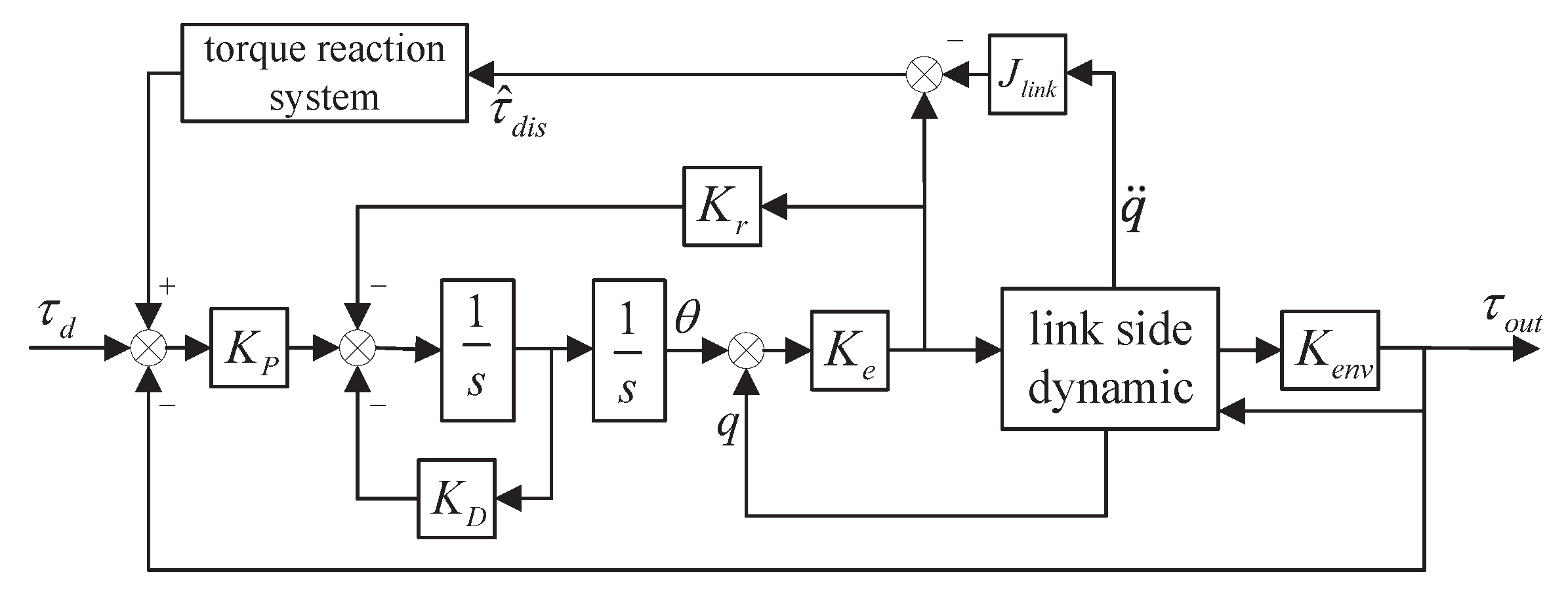
4.2.2. Nonlinear Disturbance Compensation on the Link Side
In addition to the inertial force, the link side includes the effects of other moments such as Coriolis force, gravity, and external environmental forces. Therefore, it is necessary to construct a force reaction system to compensate for this part of the moment at the system reference control input, as shown in
Figure 10.
When the reference input
= 0, the transfer function of the link-side disturbance input to output torque is:
Simultaneous Formulas (28) and (31) to obtain the transfer function of the link-side disturbance to the reference input torque:
Therefore, the form of the force reaction system is Formula (32). The other forces on the link side, except the inertial force, are regarded as disturbances, and the disturbances are estimated as the input of the force reaction system. The influence of the nonlinear torque disturbance on the link side can be compensated for by superimposing the output result into the reference input torque. It is worth noting that both the gravity on the link side and the moments interacting with the environment are included in
. This process realizes the compensation of gravity and environmental force. Estimates of disturbance torques are obtained using the model-based direct estimation method of external forces in
Section 3. The complete system control structure is shown in
Figure 11.
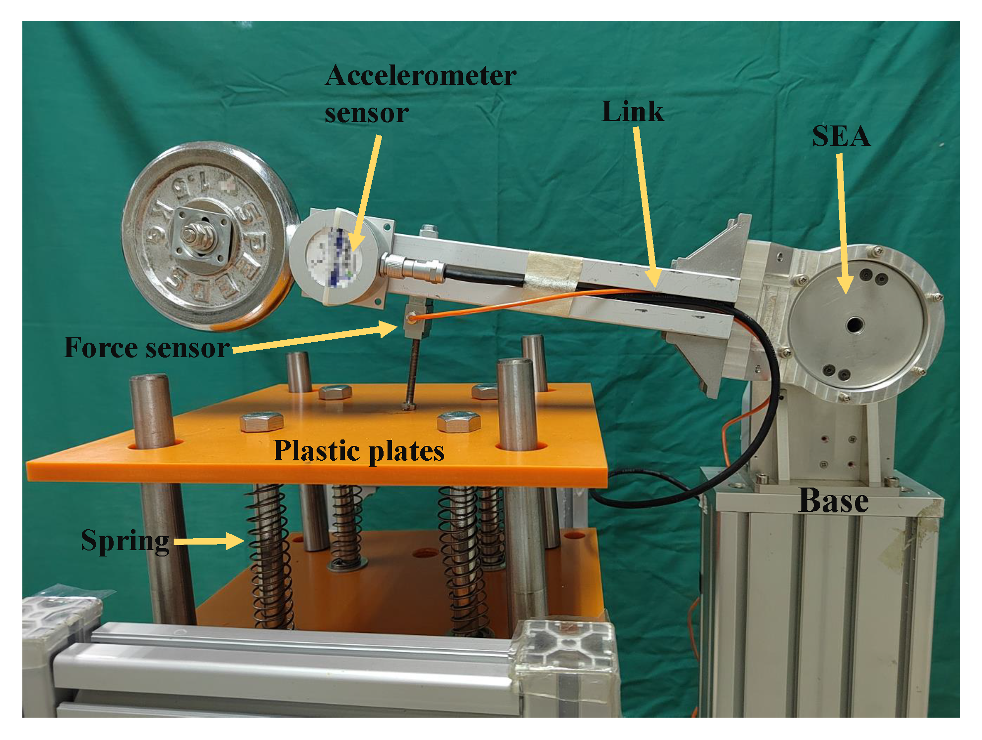
5. Experimental Setup
To facilitate the comparison of different performances of external force estimation, series elastic actuators are used as the single-DOF robot driving joints, as shown in
Figure 12. The spring stiffness is 280 N·m/rad, And SEA system parameters are shown in
Table 1. In the experiment, a 13-bit photoelectric encoder is installed on the motor side to collect motor position information for motor control; a 16-bit photoelectric encoder is installed on the link side to manage the position information of the link. This is a general configuration of a series elastic actuator. The angular acceleration of the link side is measured by directly mounting a three-dimensional accelerometer on the link side as an additional input for EKF data fusion; accelerometer parameters are shown in
Table 2. Between the robot link and the external environment (spring plate), a force sensor is installed as an intermediate medium to directly measure the external moment acting on the link as a standard reference for estimating external forces by different methods; the force sensor parameters are shown in
Table 3.
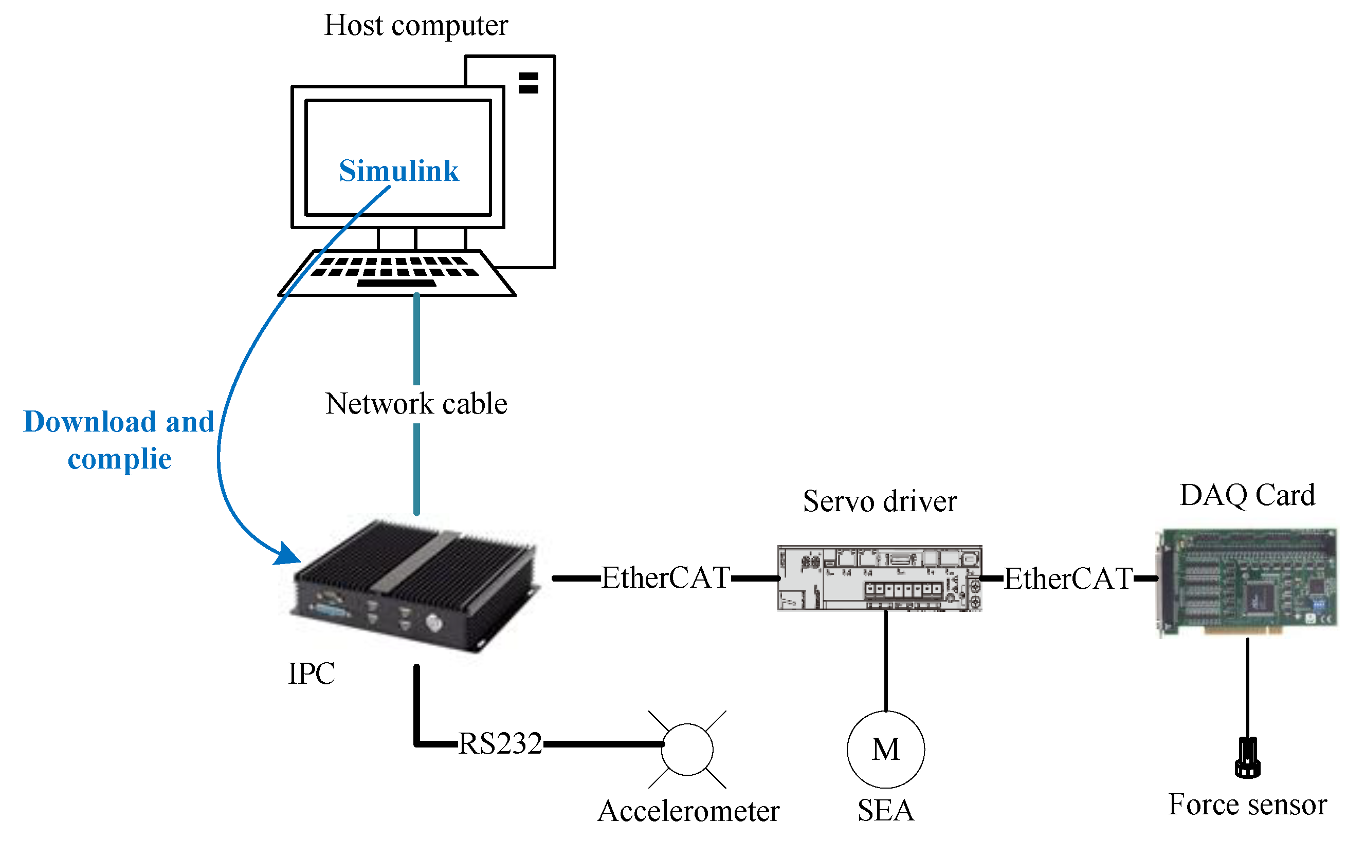
The control system platform is based on the Matlab/Simulink environment. The control system runs on the Simulink Real-Time operating system, and the basic structure is shown in
Figure 13. It mainly includes a host computer, a target industrial computer, servo drivers, serial elastic driver, and other sensors. The development host computer runs on Windows and in the Matlab/Simulink environment; the target industrial computer is connected to the development host computer via the Ethernet. It runs the Simulink Real-Time system, and acts as the EtherCAT master station, connects to the motor servo amplifier and data acquisition card through the EtherCAT bus, realizes real-time state monitoring, feedback, and commands sent from the motor. In addition, the accelerometer data are connected to the target IPC through the RS-232 interface. The sampling time is 2 ms.
6. Results and Discussion
6.1. Experimental Results of Dynamic Parameter Identification
After the signal acquisition and processing are completed, the processed state data are used to construct the data matrix required for the least-squares parameter identification, and the elastic-joint dynamic parameters to be identified are calculated, as shown in
Table 4.
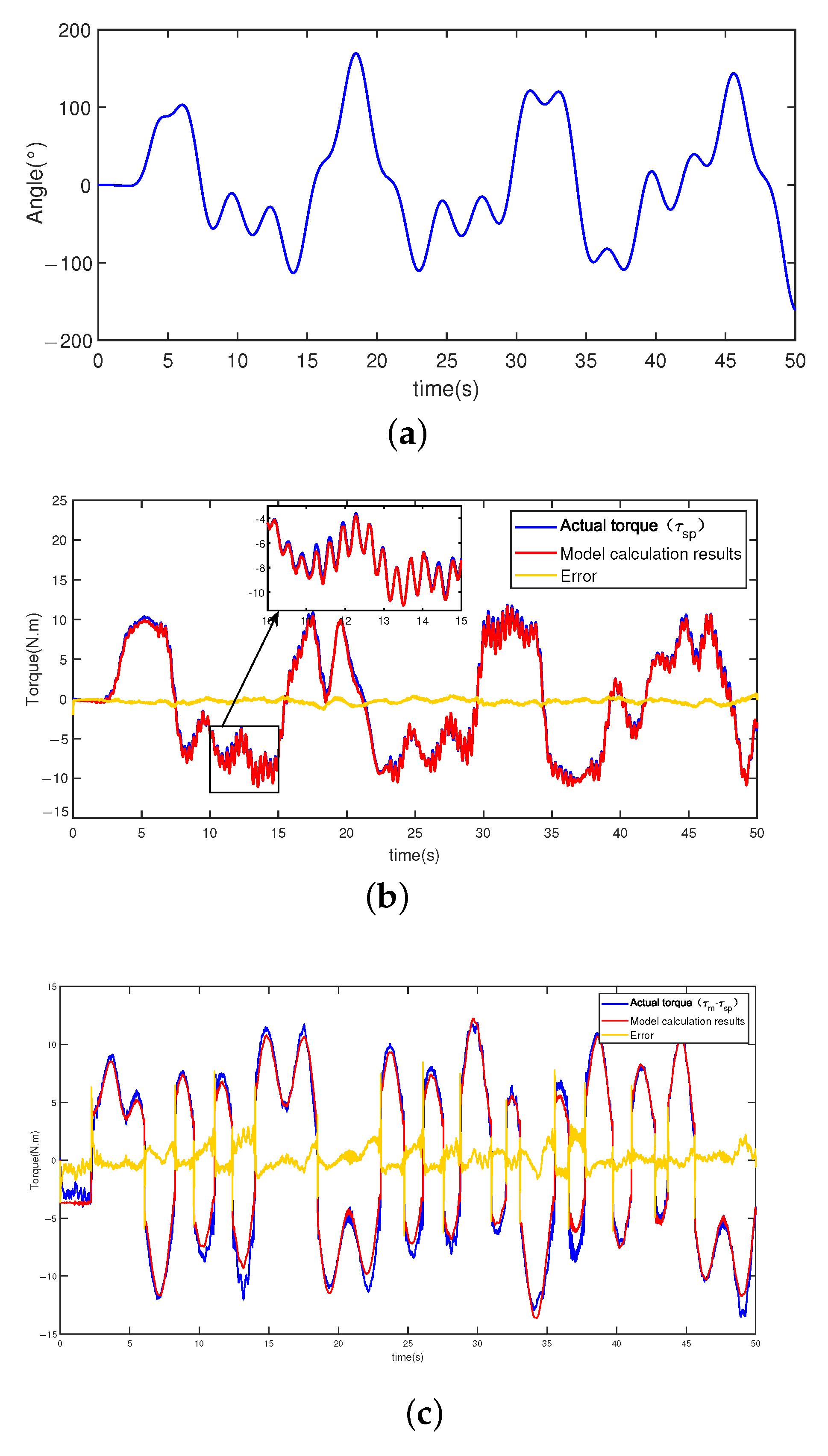
To verify the accuracy of the identification results, the robot is moved according to different random trajectories. Similar to the identification process, sensors collect the joint angle and drive torque signals during the robot’s motion. Then, the collected signals are processed and substituted into the dynamic equation.
Figure 14 shows the similarity and the signal error between the torque estimation result and the actual torque output.
From the model verification results, it can be seen that under random trajectory excitation, the calculation results of the dynamic model on the link side have small error and follow the actual torque, which verifies the validity and accuracy of the parameter-identification results. For the motor side, the dynamic calculation results also follow the actual torque during the entire moving process. Still, there is a very large model calculation error at the zero-crossing point of the speed. Analyzing the dynamic equations on the motor side shows that the error mainly comes from the inaccurate friction model. Therefore, the motor inertia parameters identified are only rough results. In this paper, the dynamic model of the link side and the elasticity of the torsion spring are used for direct joint external force estimation.
6.2. Experimental Results of External Torque Estimation
In this work, by controlling the motor to make the robot link move and interact with the external environment (spring plate), we study the different effects of methods proposed in
Section 4 on detecting external forces during the entire interaction process.
The entire interaction process is divided into seven stages.
Stage 1: The link is stationary at an angle close to the spring plate but not in contact;
Stage 2: The link starts to move until it contacts the spring plate;
Stage 3: The link presses down on the spring plate;
Stage 4: The link and spring plate remain relatively stationary;
Stage 5: The link leaves the spring plate until there is no contact with the spring plate;
Stage 6: After leaving the spring plate, the spring plate is free to vibrate due to the joint’s flexibility;
Stage 7: The link is stationary at the starting angle.
As shown in
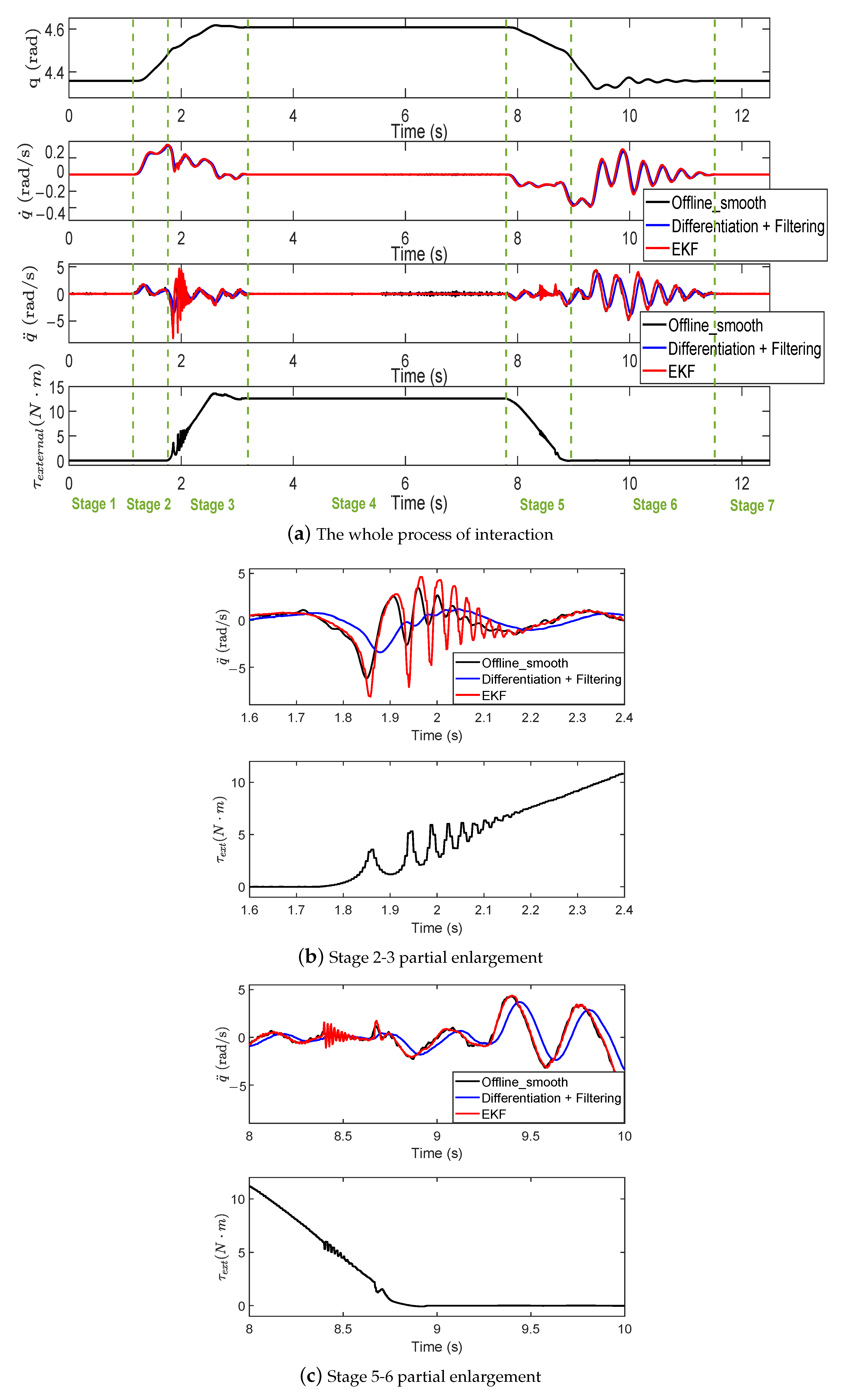
Figure 15, the state information of the link is recorded, including the angle, angular velocity, and angular acceleration of the link side. “EKF” represents the link status information calculated in real time by fusing sensor data using the EKF. “Differentiation + Filtering” represents the direct differencing and filtering of the position signals collected in real time on the control system. “Offline smooth” denotes the result of offline differencing and sliding window averaging of the joint link side angle signal returned by the photoelectric encoder. The mean smoothing of the signal leads to the loss of the high-frequency component of the state information, but does not cause a delay in the signal, and it is used for comparative reference of the robot system real-time status information.
It can be seen that the angular velocity and angular acceleration information obtained by the commonly used method of differential post-filtering of the position will cause the delay of the signal, and the high-frequency components of the signal will be filtered out by the filter, resulting in a relatively low upper limit of the system bandwidth. However, by merging the accelerometer signal with the photoelectric encoder signal through the EKF, a velocity signal and an acceleration signal with almost no delay and a sufficiently wide bandwidth can be obtained. For example, at 1.7–2.2 s and 8.4–8.7 s, EKF can detect fast-changing high-frequency acceleration signals. In other cases, the results of EKF are similar to those of offline sliding smoothing, which proves the accuracy of the results obtained by EKF fusion of two sensor signals.
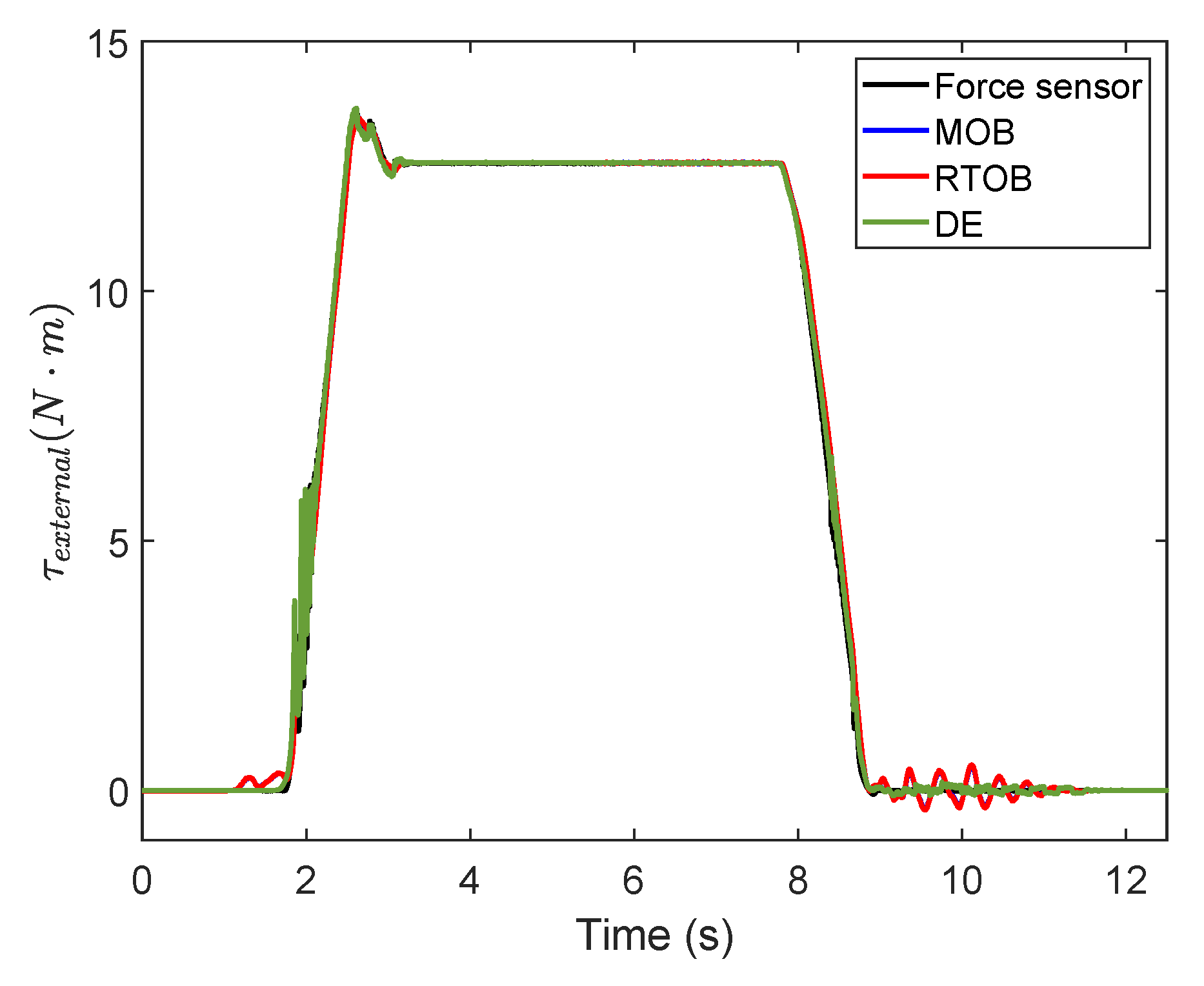
In the case of the MOB and the RTOB for external torque estimation, the angular velocity signal input to the observer is obtained by direct differential plus filtering of the position signal returned from the photoelectric encoder, because these two methods are proposed based on the unavailability of the angular acceleration signal. The model-based direct torque estimation method uses the angular acceleration signal estimated by EKF directly. The external force-estimation results of the three methods are shown in
Figure 16. The outcomes measured by the force sensor are also displayed.
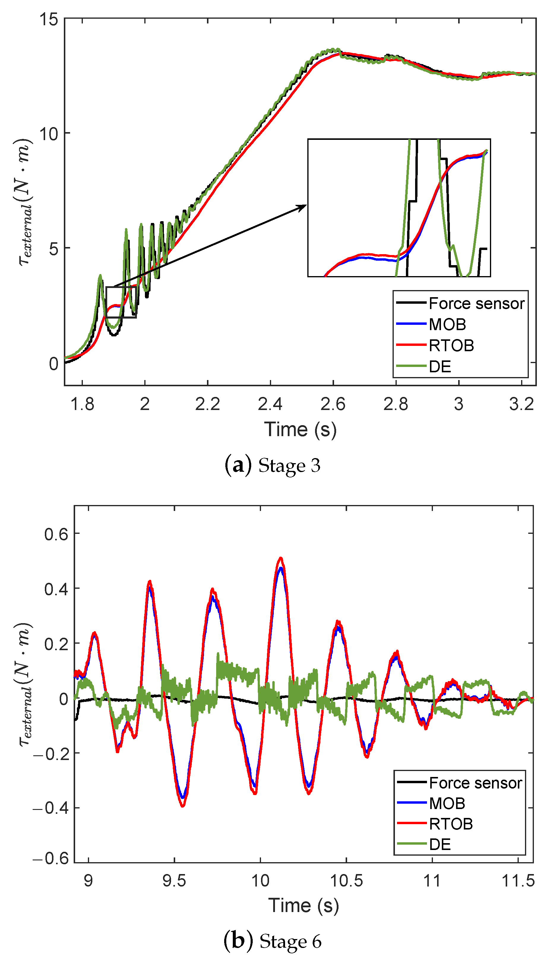
Among them, the most significant difference lies in stage 3 (pressing process), and stage 6 (free oscillation of the link), and the external force-estimation results of these two stages are displayed separately in
Figure 17a,b. Stage 3 is the process in which the link presses the spring plate. The external torque acting on the link in this process changes rapidly and can reflect the following rapidity of the external torque estimation. Stage 6 is the free oscillating motion of the link caused by the joint flexibility after the link leaves the spring plate, in which the link is not subject to external torque and the external torque estimation result should be zero. It can be seen that the results of MOB and RTOB are the same. The reason for this is that the mathematical models of the two methods are essentially the same. The results obtained by both methods have a more pronounced delay compared to the reference value (measured directly by the force sensor), the external torque follows more slowly, and the presence of the system state delay leads to the detection of large external torque fluctuations even when the link is not subjected to external torque. However, the direct estimation method is characterized by high sensitivity and precision in external torque estimation.
6.3. Experimental Results of Force Control Based on Link-Side Acceleration Estimation
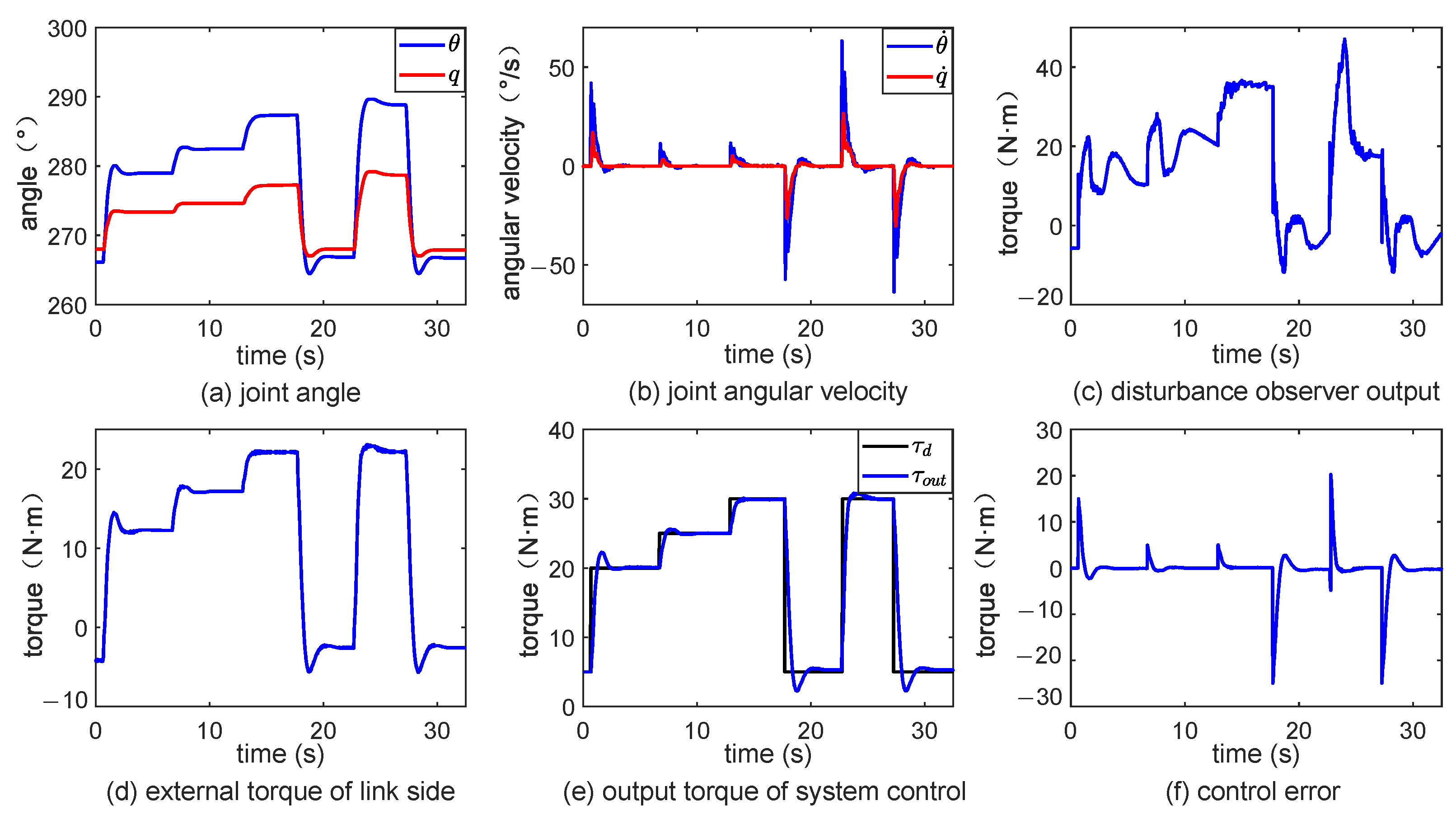
Simulink Real-Time project was built according to the theoretical design, and the output torque results of the system were recorded. It can be seen from
Figure 18 that the controller can control the joint of the robot to output a specified torque. In the configuring system parameters, the role of the environment is modeled as a spring with a stiffness of 280 N·m/rad. However, the interaction between the link and the environment in the actual process may be more complex and have varying stiffness. Therefore, there are overshoots and jitter in the dynamic adjustment process. Moreover, there is a certain deviation in the link output when the system is steady.
Resonant proportional control is used for force control on the link side. Elastic feedback gain is used to change the resonance ratio and configure the pole of the characteristic equation of the closed-loop system to suppress the resonance. Nonlinear disturbances are estimated using an acceleration-based model of external moments and compensated for by a force reaction system to achieve link force control. Numerical simulation results prove the effectiveness of the force control algorithm.


