Communication

Fault Detection and Localisation of a Three-Phase Inverter with Permanent Magnet Synchronous Motor Load Using a Convolutional Neural Network

Faculty of Automatic Control, Robotics and Electrical Engineering, Poznan University of Technology, 60-965 Poznań, Poland
*
Author to whom correspondence should be addressed.
Actuators 2023, 12(3), 125; https://doi.org/10.3390/act12030125
Submission received: 27 January 2023 / Revised: 9 March 2023 / Accepted: 11 March 2023 / Published: 15 March 2023
(This article belongs to the Special Issue 10th Anniversary of Actuators)

Abstract

:
Fault-tolerant control of a three-phase inverter can be achieved by performing a hardware reconfiguration of the six-switch and three-phase (6S3P) topology to the four-switch and three-phase (4S3P) topology after detection and localisation of the faulty phase. Together with hardware reconfiguration, the SVPWM algorithm must be appropriately modified to handle the new 4S3P topology. The presented study focuses on diagnosing three-phase faults in two steps: fault detection and localisation. Fault detection is needed to recognise the healthy or unhealthy state of the inverter. The binary state recognition problem can be solved by preparing a feature vector that is calculated from phase currents (ia, ib, and ic) in the time and frequency domains. After the fault diagnosis system recognises the unhealthy state, it investigates the signals to localise which phase of the inverter is faulty. The multiclass classification was solved by a transformation of the three-phase currents into a single RGB image and by training a convolutional neural network. The proposed methodology for the diagnosis of three-phase inverters was tested based on a simulation model representing a laboratory test bench. After the learning process, fault detection was possible based on a 128-sample window (corresponding to a time of 0.64 ms) with an accuracy of 99 percent. In the next step, the localisation of selected individual faults was performed on the basis of a 256-sample window (corresponding to a time of 1.28 ms) with an accuracy of 100 percent.

1. Introduction

Households and industrial plants are equipped with many electric drives that have limited lifetimes. The proper maintenance of electric drives with mechanical loads is essential for reducing the amount of waste electrical and electronic equipment (WEEE) [1,2,3,4,5,6]. The time that a machine can satisfactorily operate before requiring repair or replacement is called the remaining useful life (RUL). The RUL can be monitored by changes in characteristics over time, which are caused by the drive and rotating machine. Mechanical vibrations will change due to bearing failure [7,8,9,10,11,12], unbalance, changes in the mechanical stiffness of the shaft, and changes in the moment of inertia [13,14,15,16]. Mechanical loading can be characterized by one mechanical resonance in a two-mass mechanical system [17,18,19,20,21], two or three mechanical resonances in a three- or four-mass system [22,23,24,25], or multiple mechanical resonances in a multi-mass system [13,14,15]. Mechanical resonance is characterized by mechanical vibrations [26]. These problems can lead to inverter overloading and faults in the three-phase inverter. According to [27,28,29,30,31], the inverter fault is mainly caused by an electronic switch. The problem is a fault in the control circuit of a single inverter switch. In the previous stage of the study, it was shown that it is possible to effectively control a three-phase inverter having a 6S3P (six-switch and three-phase) topology when one or two switches in the same phase of the inverter fail; such control requires reconfiguration to a 4S3P (four switches and three phases) topology [32,33]. Therefore, in this research stage, the authors focused on the feature extraction and classification of inverter faults in the cloud. This approach can limit the system deployment time compared with hard embedded programming.

2. Fault-Tolerant Control System
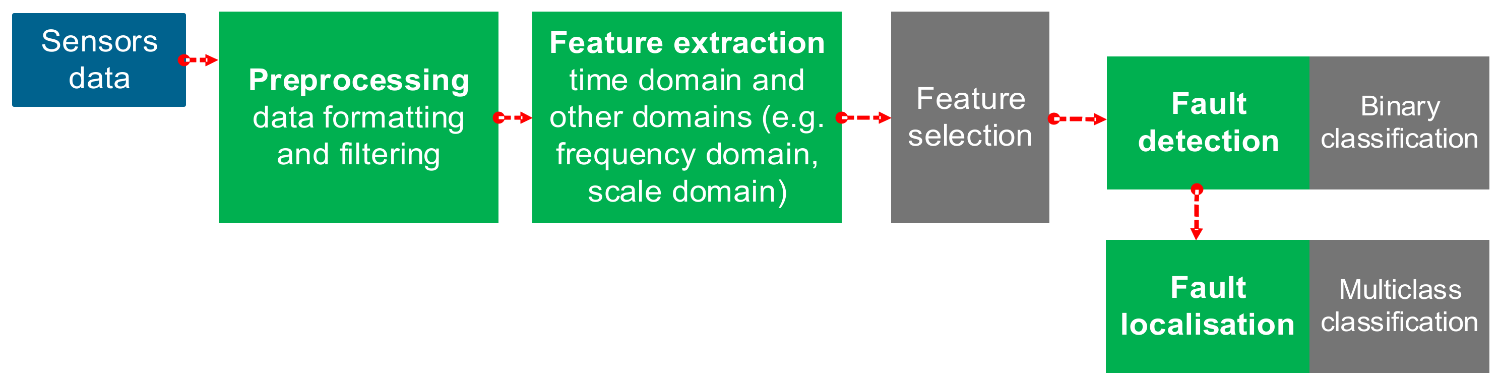
The considered fault-tolerant control system is a control system that can operate under constrained conditions compared with a healthy three-phase inverter. After fault detection and localisation of the faulty inverter phase, the hardware is reconfigured to a 4S3P topology. The fault-tolerant control system consists of two hardware capacitors connected to the PMSM (permanent magnet synchronous motor) phase instead of the faulty inverter phase. Figure 1 shows a healthy 6S3P topology and the reconfiguration to 4S3P in phase C of the PMSM after fault detection and localisation.
In a previous stage of investigation, the 6S3P and 4S3P topologies were successfully tested on a laboratory bench (Figure 2) [32,33]. The laboratory rig was equipped with the ALFINE-TIM ALS-G3-1369 controller board, which was based on using the Analog Devices SHARC® ADSP-21369 digital signal processor (DSP), ALFINE-TIM three-phase inverter, and LABINVERTER P3-5.0/550MFE. Further details of the laboratory setup, including the PMSM parameters, have been published in [34].
The reconfiguration between the 6S3P and 4S3P topology is accomplished by the Pfault switch (see Figure 3), which is controlled by the fault diagnosis module described in the following sections. Furthermore, after hardware reconfiguration from 6S3P to 4S3P, the SVPWM (space vector pulse width modulation) switching method must be modified for proper operation [32,33] in the new topology. Other parts of the control system remain unchanged. However, the number of available voltage vectors is reduced. The parameters of the current controllers R(iq), R(id), and the speed controller R(ω) are unchanged. Empirical tests conducted in a previous research phase confirm that only a modification of the SVPWM is required when the topology is changed to 4S3P after a single-phase fault.
A simulation model of the controller and hardware was created based on the laboratory setup. The inverter model and SVPWM were designed using the MathWorks Simscape Electrical™ tool. The healthy 6S3P inverter was simulated with a reference speed nref equal to 1200 rpm. The simulation time was set to 2 s with a sampling time of 5 μs. The velocity and current controllers on the q and d axes operate correctly as shown in Figure 4. The fault was simulated at a time equal to 1 s for each switch in the inverter. A total of six datasets were recorded for the fault of the upper and lower switches in each of phases A, B, and C. The data for the upper switches are shown in Figure 5. However, due to the 1 s time scale, only the long-term response of the system speed is easily visible. Therefore, the time zoom for the first 4000 samples after the fault is shown in Figure 6, where the shape of the currents can be observed.

3. Fault Detection

A data-driven fault diagnosis system can be developed with fault detection and fault localisation as shown in Figure 7. In this section, the focus is on fault detection, which means that it is only important to have information about the health of the system in one of two states: normal or abnormal. The normal state means that the system is working properly and that there are no symptoms to be concerned about. The abnormal state means that some symptoms of the system are outside of the range that is considered normal. The designed system needs to recognize these two states. This problem can be solved by performing a binary classification with the class labels of “normal” and “fault”. The first stage of preparation for the binary classification is data collection for each class and features extraction in the desired time, frequency, or time–frequency domain.
The sensor presented in Figure 7 can be of any kind; it can be an additional sensor only for fault diagnosis or a sensor that is already present in the system and being used by the control algorithms. The electromechanical machine or power system can be investigated by using many different sensors and signals: current [35,36] and voltage [37,38], torque [12,39], angular velocity/position [40,41], linear three-axis acceleration/speed/position [42,43], Doppler laser vibrometer [44], transmission coefficient and reflexion coefficient of an omnidirectional antenna [45], strain/tension [46,47,48,49], power consumption [50,51,52,53], internal/external temperature at selected points [11,54] or surface temperature using a thermal camera [55,56]; furthermore, depending on the frequency range, displacement [57], vibrations [58,59,60,61], sound [62,63,64], sound from several microphones [65] or ultrasound [66,67], vibro-acoustic [7], chemical analyses of lubrication [68,69], chemical analyses using spectral imaging [70,71,72,73], camera imaging in the human colour spectrum [74,75,76,77], and converting signals to virtual image [78,79,80,81] are also possible.
In the current research, data were collected from the currents in phases A, B, and C. These data were divided into a time domain window of 128 samples (Figure 8). Six time domain features were extracted for each current in the window: the standard deviation, variance, median, minimum, maximum, and peak-to-peak. Three frequency-domain features were also extracted: the maximum magnitude frequency component index, minimum magnitude frequency component index, and peak-to-peak frequency magnitude. In total, 27 features were used to train the classification to detect the “normal” or “fault” class. A single-switch fault was considered for each switch in the 6S3P topology. At the current stage of research, 11934 observations were used in the training process and 1325 observations were used in the test. The observation time window had 12 samples overlapping with the previous time window. Training was performed in MathWorks Matlab R2022b using the Statistics and Machine Learning Toolbox version 12.4. More than 16 classifiers with different structures (i.e., linear discriminant; SVM—support vector machine; KNN—k-nearest neighbours; narrow neural network; decision tree; bagged tree) were trained, with a test accuracy of greater than 99% for the selected features (Figure 9).

4. Fault Localisation

Fault location provides more information about fault detection. Fault localisation indicates which part of the system is faulty and the extent of the fault. Therefore, the inverter fault diagnosis has been divided into separate tasks: (1) fast fault detection; and (2) the inverter fault localisation phase. Investigating the inverter fault in the 6S3P topology requires identifying the phase where the switch is broken in order to properly change the structure to a 4S3P topology; this problem can be solved by multi-label classification using the ‘A’, ‘B’, or ‘C’ class labels of the faulty phase.
At the current stage of the research, the time domain signal is transformed into an image. The dataset prepared for each class was used to train a CNN (convolutional neural network). The single RGB image consists of three channels: red, green, and blue. The data collection was studied in time window equal to 256 samples, which results in an image size of 16 × 16 pixels. In this approach, the time domain signal was converted into an image with a size of 16 × 16 × 3 (Figure 10), where red, green, and blue colours represent the current in phase A, current in phase B, and current in phase C, respectively. The time domain data of the 256 samples of a single phase are transformed into a 16 × 16 matrix, which is treated as an image. The image columns contain the consecutive samples of the signal. Example images at the same observation time for each phase are shown in Figure 11. There were 618 RGB images for each class, which provided a total of 1854 images. The time window of a single observation had 64 samples overlapping with the previous time window. All images were divided into training, validation, and test sets.
The three-label classifier (‘A’, ‘B’, and ‘C’) was designed as a convolutional neural network (CNN). An essential part of the design process is the selection of a CNN structure capable of RGB image recognition. At the current stage of the research, the CNN consists of seven layers (Figure 12 [left]): (1) an image input with a size of 16 × 16 × 3; (2) a 2D convolution of 8 × 8 × 3 convolutions; (3) a batch normalization with 20 channels; (4) ReLU; (5) three fully connected layers; (6) softmax; and (7) a classification output with class ‘A’, ‘B’, and ‘C’. The CNN training was performed in MathWorks Matlab R2022b using Deep Learning Toolbox version 14.5. The training result is shown in Figure 12 (bottom right). The total number of trained parameters in the CNN is 8763. The test accuracy was 100% for the test dataset.

5. Discussion

Fault diagnosis firstly requires the detection of a fault; secondly, it requires the location of the fault. The three-phase inverter studied in the 6S3P topology can have one switch (upper or lower) be unhealthy in one phase. An unhealthy condition means that the circuit is opened by a non-working transistor, but the diode is conducting normally. Such a situation is typical for transistor gate driver failures. In the methodology proposed in the first stage, the fault of the inverter is detected by a vector of features that are calculated for each phase current. The features are in the time and frequency domain and are calculated from samples that are collected in a short time window. After fault detection, more samples in a wider time window are examined. The phase currents ia, ib, and ic collected in the time window are transformed into a matrix with a size of 16 × 16 × 3, which corresponds to a 16 × 16 RGB image. The fault simulation allows for the preparation of the data acquisition. In total, six defects were investigated. For each transistor in phase, a fault was identified and labelled in the three classes corresponding to phases ‘A’, ‘B’, and ‘C’. This approach allowed us to transform the collected currents into RGB images that were labelled by phase. The RGB image recognition was designed by selecting the CNN structure and performing the training process. The result of the localisation test (multi-class RGB image classification) with 100% accuracy confirms the appropriateness of this approach.
The approach of the RGB image localisation was compared with the build of the reference localisation classifiers based on the selected 27 features used for fault detection. For all reference localisation classifiers, the time window size was equal to the 256 samples. Therefore, all features were recalculated in each window with 25 overlap samples. Each of the reference classifiers had a worse accuracy (lower than the 99.4%) than proposed approach. The confusion matrix and the accuracy percentage of the reference classifiers are presented in Table 1.
The detection of the inter-turn short circuit for the PMSM phase was investigated in [82], where three different CNN structures were compared. However, the diagnosis system operated at three full periods of the phase current signal (500 samples), and the fault detection was performed within a time of 0.06 s. At a previous stage of the investigation, the fault detection of the inter-turn short circuit was obtained based on 200 samples, which was equivalent to 0.02 s of measurement [83]. Instead of using a CNN model, fuzzy logic can also be applied in PMSM fault diagnosis [84]; this approach requires an appropriate formulation of fuzzy rules by a specialist in the field of electrical drives. The single-power switch, open-circuit fault was detected 0.08 s after the fault occurrence. In [12], a CNN diagnosed three motor conditions (health motor, demagnetised motor, and motor with bearing fault) based on features extracted in the frequency domain. The drawback of conducting a conversion from time domain data to the frequency domain is that a long time window (large number of samples) is needed to achieve good resolution in the frequency domain, e.g., a time window of 1 s will lead to 1 Hz resolution. Therefore, a long time window is not appropriate for quickly detecting and localising a fault occurring in a 6S3P inverter. The diagnosis system with demagnetisation and semi-demagnetisation faults can use other domain characteristics by applying a DWT (discrete wavelet transform) [85], which requires the selection of the level of DWT decomposition and the choice of mother wavelet shape (one low-pass filter for approximation and one high-pass filter for detail). The suggested approach is to calculate the fault detection of open switch use features in the time and frequency domain in a short time window for fast fault disclosure. The advised data-driven method for fault localisation uses raw data and deep learning without the need for extraction features from the frequency or scale domain. The proposed approach operates around one period of the phase currents with faster fault detection based on a 128-sample window (corresponding to a time of 0.64 ms) and faster localisation of faulty inverter phase based on a 256-sample window (corresponding to a time of 1.28 ms).

6. Conclusions

Research was carried out at TRL (technology readiness level) 1 to validate the proof of concept. Further research will be performed to increase the TRL to higher levels to validate the rotary electric machine (electric drive) with a fault diagnosis system in the laboratory environment. At TRL 1, a single fault of an energo-electronic switch in the six-switch and three-phase (6S3P) topology was considered. This leads to considering one of six possible faults; however, faults of two switches in the same phase were tested. The 4S3P topology with modified SVPWM can operate properly with only one faulty phase, but not more. Multiple faults in different 6S3P phases are less probable. However, the authors are currently developing multiple fault diagnoses for all possible combinations (63 fault classes) of switch faults in a three-phase inverter. The preliminary research of those 63 classes provides less satisfactory results and needs more effort invested into them in future research. The authors at the current research stage considered an abrupt fault without an incipient or intermittent part. Fault detection should return an abnormal state; however, fault localisation will need a further extension for new types of faults; that extension could require a different approach or a retraining of a convolutional neural network with an extended phase current RGB images dataset. Another aspect of possible future research is an investigation of the power distribution system, with the detection and localisation of one of many SVPWM inverter connected in power grid. The issue of a short circuit or break circuit can be found in a hybrid circuit system [86] or vehicles with an internal power grid system, e.g., a car, aircraft [87], or ship.
In the event of a transistor fault in a three-phase inverter with 6S3P topology, it is possible to operate in a fault-tolerant manner after hardware reconfiguration to 4S3P. This approach can be used when one phase fails. The presented research with the proposed methodology in two steps allows for the proper fault detection and precise localisation of the faulty phase. Fault detection is the first step and is a trigger for the execution of the fault localisation part of the system. After fault detection, the control system can be shut down or the reference speed can be slightly reduced to slow down the system. In parallel, the localisation module can detect which phase of the inverter is faulty in order to switch one of the PMSM phases between capacitors. After hardware reconfiguration and modification of the SVPWM algorithm, the system can still operate normally under the constrained current conditions compared with a healthy state. The proposed multi-class classification of phase currents as RGB images provides satisfactory results at the current research stage.

Author Contributions

Feature and RGB image extraction, D.Ł.; fault detection and localisation classifier design, D.Ł.; two-stage fault diagnosis approach, D.Ł. and S.B.; faults selection of three-phase inverter, D.Ł. and S.B.; data generation of three-phase inverter faults, K.S. All authors have read and agreed to the published version of the manuscript.

Funding

This work has been funded by the National Science Centre, Poland (Grant No. 2015/17/N/ST7/03796).

Data Availability Statement

Not applicable.

Conflicts of Interest

The authors declare no conflict of interest.

References

  1. Pan, X.; Wong, C.W.Y.; Li, C. Circular Economy Practices in the Waste Electrical and Electronic Equipment (WEEE) Industry: A Systematic Review and Future Research Agendas. J. Clean. Prod. 2022, 365, 132671. [Google Scholar] [CrossRef]
  2. Rene, E.R.; Sethurajan, M.; Kumar Ponnusamy, V.; Kumar, G.; Bao Dung, T.N.; Brindhadevi, K.; Pugazhendhi, A. Electronic Waste Generation, Recycling and Resource Recovery: Technological Perspectives and Trends. J. Hazard. Mater. 2021, 416, 125664. [Google Scholar] [CrossRef]
  3. Kan, Y.; Liu, H.; Yang, Y.; Wei, Y.; Yu, Y.; Qiu, R.; Ouyang, Y. Two Birds with One Stone: The Route from Waste Printed Circuit Board Electronic Trash to Multifunctional Biomimetic Slippery Liquid-Infused Coating. J. Ind. Eng. Chem. 2022, 114, 233–241. [Google Scholar] [CrossRef]
  4. Ji, X.; Yang, M.; Wan, A.; Yu, S.; Yao, Z. Bioleaching of Typical Electronic Waste—Printed Circuit Boards (WPCBs): A Short Review. Int. J. Environ. Res. Public Health 2022, 19, 7508. [Google Scholar] [CrossRef]
  5. Marinello, S.; Gamberini, R. Multi-Criteria Decision Making Approaches Applied to Waste Electrical and Electronic Equipment (WEEE): A Comprehensive Literature Review. Toxics 2021, 9, 13. [Google Scholar] [CrossRef]
  6. Breque, M.; De Nul, L.; Petridis, A.; Directorate-General for Research and Innovation (European Commission). Industry 5.0: Towards a Sustainable, Human Centric and Resilient European Industry; Publications Office of the European Union: Luxembourg, 2021; ISBN 978-92-76-25308-2. [Google Scholar] [CrossRef]
  7. Wang, X.; Mao, D.; Li, X. Bearing Fault Diagnosis Based on Vibro-Acoustic Data Fusion and 1D-CNN Network. Measurement 2021, 173, 108518. [Google Scholar] [CrossRef]
  8. Liu, D.; Cheng, W.; Wen, W. Rolling Bearing Fault Diagnosis via STFT and Improved Instantaneous Frequency Estimation Method. Procedia Manuf. 2020, 49, 166–172. [Google Scholar] [CrossRef]
  9. Miao, Y.; Zhang, B.; Li, C.; Lin, J.; Zhang, D. Feature Mode Decomposition: New Decomposition Theory for Rotating Machinery Fault Diagnosis. IEEE Trans. Ind. Electron. 2023, 70, 1949–1960. [Google Scholar] [CrossRef]
  10. Han, T.; Ding, L.; Qi, D.; Li, C.; Fu, Z.; Chen, W. Compound Faults Diagnosis Method for Wind Turbine Mainshaft Bearing with Teager and Second-Order Stochastic Resonance. Measurement 2022, 202, 111931. [Google Scholar] [CrossRef]
  11. Dhiman, H.S.; Deb, D.; Muyeen, S.M.; Kamwa, I. Wind Turbine Gearbox Anomaly Detection Based on Adaptive Threshold and Twin Support Vector Machines. IEEE Trans. Energy Convers. 2021, 36, 3462–3469. [Google Scholar] [CrossRef]
  12. Wang, C.-S.; Kao, I.-H.; Perng, J.-W. Fault Diagnosis and Fault Frequency Determination of Permanent Magnet Synchronous Motor Based on Deep Learning. Sensors 2021, 21, 3608. [Google Scholar] [CrossRef]
  13. Łuczak, D. Nonlinear Identification with Constraints in Frequency Domain of Electric Direct Drive with Multi-Resonant Mechanical Part. Energies 2021, 14, 7190. [Google Scholar] [CrossRef]
  14. Brock, S.; Luczak, D.; Nowopolski, K.; Pajchrowski, T.; Zawirski, K. Two Approaches to Speed Control for Multi-Mass System with Variable Mechanical Parameters. IEEE Trans. Ind. Electron. 2016, 64, 3338–3347. [Google Scholar] [CrossRef]
  15. Luczak, D. Mathematical Model of Multi-Mass Electric Drive System with Flexible Connection. In Proceedings of the 19th International Conference On Methods and Models in Automation and Robotics (MMAR), Miedzyzdroje, Poland, 2–5 September 2014; pp. 590–595. [Google Scholar]
  16. Luczak, D.; Nowopolski, K. Identification of Multi-Mass Mechanical Systems in Electrical Drives. In Proceedings of the 2014 16th International Conference on Mechatronics—Mechatronika (ME), Brno, Czech Republic, 3–5 December 2014; pp. 275–282. [Google Scholar]
  17. Wróbel, K.; Serkies, P.; Szabat, K. Model Predictive Base Direct Speed Control of Induction Motor Drive—Continuous and Finite Set Approaches. Energies 2020, 13, 1193. [Google Scholar] [CrossRef] [Green Version]
  18. Szabat, K.; Wróbel, K.; Dróżdż, K.; Janiszewski, D.; Pajchrowski, T.; Wójcik, A. A Fuzzy Unscented Kalman Filter in the Adaptive Control System of a Drive System with a Flexible Joint. Energies 2020, 13, 2056. [Google Scholar] [CrossRef] [Green Version]
  19. Nalepa, R.; Najdek, K.; Wróbel, K.; Szabat, K. Application of D-Decomposition Technique to Selection of Controller Parameters for a Two-Mass Drive System. Energies 2020, 13, 6614. [Google Scholar] [CrossRef]
  20. Wicher, B.; Brock, S. Comparison of Robustness of Selected Speed Control Systems Applied for Two Mass System with Backlash. In Advanced, Contemporary Control; Bartoszewicz, A., Kabziński, J., Kacprzyk, J., Eds.; Springer International Publishing: Cham, Switzerland, 2020; pp. 1371–1382. [Google Scholar]
  21. Guerra, R.H.; Quiza, R.; Villalonga, A.; Arenas, J.; Castaño, F. Digital Twin-Based Optimization for Ultraprecision Motion Systems With Backlash and Friction. IEEE Access 2019, 7, 93462–93472. [Google Scholar] [CrossRef]
  22. Luczak, D.; Siwek, P.; Nowopolski, K. Speed Controller for Four-Mass Mechanical System with Two Drive Units. In Proceedings of the 2015 IEEE 2nd International Conference on Cybernetics (CYBCONF), Gdynia, Poland, 24–26 June 2015; pp. 449–454. [Google Scholar]
  23. Hung, Y.-H.; Lee, C.-Y.; Tsai, C.-H.; Lu, Y.-M. Constrained Particle Swarm Optimization for Health Maintenance in Three-Mass Resonant Servo Control System with LuGre Friction Model. Ann. Oper. Res. 2022, 311, 131–150. [Google Scholar] [CrossRef]
  24. Korendiy, V.; Kachur, O.; Gursky, V.; Gurey, V.; Maherus, N.; Kotsiumbas, O.; Havrylchenko, O. Kinematic and Dynamic Analysis of Three-Mass Oscillatory System of Vibro-Impact Plate Compactor with Crank Excitation Mechanism. Vibroengineering PROCEDIA 2022, 40, 14–19. [Google Scholar] [CrossRef]
  25. Binder, D.; Bendrat, F.; Sourkounis, C. Model Predictive Control of a High Power Rolling-Mill Drive Considering Shaft Torque Constraints. In Proceedings of the IECON 2021—47th Annual Conference of the IEEE Industrial Electronics Society, Toronto, ON, Canada, 13–16 October 2021; pp. 1–7. [Google Scholar]
  26. Łuczak, D. Mechanical Vibrations Analysis in Direct Drive Using CWT with Complex Morlet Wavelet. Power Electron. Drives 2023, 8, 65–73. [Google Scholar] [CrossRef]
  27. Wang, B.; Cai, J.; Du, X.; Zhou, L. Review of Power Semiconductor Device Reliability for Power Converters. CPSS Trans. Power Electron. Appl. 2017, 2, 101–117. [Google Scholar] [CrossRef]
  28. Manohar, S.S.; Sahoo, A.; Subramaniam, A.; Panda, S.K. Condition Monitoring of Power Electronic Converters in Power Plants—A Review. In Proceedings of the 2017 20th International Conference on Electrical Machines and Systems (ICEMS), Sydney, NSW, Australia, 11–14 August 2017; pp. 1–5. [Google Scholar]
  29. Yang, S.; Xiang, D.; Bryant, A.; Mawby, P.; Ran, L.; Tavner, P. Condition Monitoring for Device Reliability in Power Electronic Converters: A Review. IEEE Trans. Power Electron. 2010, 25, 2734–2752. [Google Scholar] [CrossRef]
  30. Spinato, F.; Tavner, P.J.; van Bussel, G.J.W.; Koutoulakos, E. Reliability of Wind Turbine Subassemblies. IET Renew. Power Gener. 2009, 3, 387–401. [Google Scholar] [CrossRef] [Green Version]
  31. Lu, B.; Sharma, S.K. A Literature Review of IGBT Fault Diagnostic and Protection Methods for Power Inverters. IEEE Trans. Ind. Appl. 2009, 45, 1770–1777. [Google Scholar] [CrossRef]
  32. Łuczak, D.; Siembab, K. Comparison of Fault Tolerant Control Algorithm Using Space Vector Modulation of PMSM Drive. In Proceedings of the 16th International Conference on Mechatronics—Mechatronika 2014, Brno, Czech Republic, 3–5 December 2014; pp. 24–31. [Google Scholar]
  33. Siembab, K.; Zawirski, K. Modified Space Vector Modulation for Fault Tolerant Control of PMSM Drive. In Proceedings of the 2016 IEEE International Power Electronics and Motion Control Conference (PEMC), Varna, Bulgaria, 25–28 September 2016; pp. 1064–1071. [Google Scholar]
  34. Łuczak, D.; Nowopolski, K.; Siembab, K.; Wicher, B. PMSM Laboratory Stand for Investigations on Advanced Structures of Electrical Drive Control. In Proceedings of the 2015 20th International Conference on Methods and Models in Automation and Robotics (MMAR), Miedzyzdroje, Poland, 24–27 August 2015; pp. 596–601. [Google Scholar]
  35. Huang, W.; Du, J.; Hua, W.; Lu, W.; Bi, K.; Zhu, Y.; Fan, Q. Current-Based Open-Circuit Fault Diagnosis for PMSM Drives With Model Predictive Control. IEEE Trans. Power Electron. 2021, 36, 10695–10704. [Google Scholar] [CrossRef]
  36. Wu, C.; Guo, C.; Xie, Z.; Ni, F.; Liu, H. A Signal-Based Fault Detection and Tolerance Control Method of Current Sensor for PMSM Drive. IEEE Trans. Ind. Electron. 2018, 65, 9646–9657. [Google Scholar] [CrossRef]
  37. Jiang, L.; Deng, Z.; Tang, X.; Hu, L.; Lin, X.; Hu, X. Data-Driven Fault Diagnosis and Thermal Runaway Warning for Battery Packs Using Real-World Vehicle Data. Energy 2021, 234, 121266. [Google Scholar] [CrossRef]
  38. Chang, C.; Zhou, X.; Jiang, J.; Gao, Y.; Jiang, Y.; Wu, T. Electric Vehicle Battery Pack Micro-Short Circuit Fault Diagnosis Based on Charging Voltage Ranking Evolution. J. Power Sources 2022, 542, 231733. [Google Scholar] [CrossRef]
  39. Gao, S.; Xu, L.; Zhang, Y.; Pei, Z. Rolling Bearing Fault Diagnosis Based on SSA Optimized Self-Adaptive DBN. ISA Trans. 2022, 128, 485–502. [Google Scholar] [CrossRef]
  40. Feng, Z.; Gao, A.; Li, K.; Ma, H. Planetary Gearbox Fault Diagnosis via Rotary Encoder Signal Analysis. Mech. Syst. Signal Process. 2021, 149, 107325. [Google Scholar] [CrossRef]
  41. Ma, J.; Li, C.; Zhang, G. Rolling Bearing Fault Diagnosis Based on Deep Learning and Autoencoder Information Fusion. Symmetry 2022, 14, 13. [Google Scholar] [CrossRef]
  42. Kim, M.S.; Yun, J.P.; Park, P. Deep Learning-Based Explainable Fault Diagnosis Model With an Individually Grouped 1-D Convolution for Three-Axis Vibration Signals. IEEE Trans. Ind. Inform. 2022, 18, 8807–8817. [Google Scholar] [CrossRef]
  43. Zhang, X.; Zhao, Z.; Wang, Z.; Wang, X. Fault Detection and Identification Method for Quadcopter Based on Airframe Vibration Signals. Sensors 2021, 21, 581. [Google Scholar] [CrossRef] [PubMed]
  44. Abbas, S.H.; Jang, J.-K.; Kim, D.-H.; Lee, J.-R. Underwater Vibration Analysis Method for Rotating Propeller Blades Using Laser Doppler Vibrometer. Opt. Lasers Eng. 2020, 132, 106133. [Google Scholar] [CrossRef]
  45. Dutta, S.; Basu, B.; Talukdar, F.A. Classification of Motor Faults Based on Transmission Coefficient and Reflection Coefficient of Omni-Directional Antenna Using DCNN. Expert Syst. Appl. 2022, 198, 116832. [Google Scholar] [CrossRef]
  46. Zhang, X.; Niu, H.; Hou, C.; Di, F. An Edge-Filter FBG Interrogation Approach Based on Tunable Fabry-Perot Filter for Strain Measurement of Planetary Gearbox. Opt. Fiber Technol. 2020, 60, 102379. [Google Scholar] [CrossRef]
  47. Zhang, P.; Lu, D. A Survey of Condition Monitoring and Fault Diagnosis toward Integrated O&M for Wind Turbines. Energies 2019, 12, 2801. [Google Scholar] [CrossRef] [Green Version]
  48. Wu, J.; Yang, Y.; Wang, P.; Wang, J.; Cheng, J. A Novel Method for Gear Crack Fault Diagnosis Using Improved Analytical-FE and Strain Measurement. Measurement 2020, 163, 107936. [Google Scholar] [CrossRef]
  49. Fedorko, G.; Molnár, V.; Vasiľ, M.; Salai, R. Proposal of Digital Twin for Testing and Measuring of Transport Belts for Pipe Conveyors within the Concept Industry 4.0. Measurement 2021, 174, 108978. [Google Scholar] [CrossRef]
  50. Pu, H.; He, L.; Zhao, C.; Yau, D.K.Y.; Cheng, P.; Chen, J. Fingerprinting Movements of Industrial Robots for Replay Attack Detection. IEEE Trans. Mob. Comput. 2022, 21, 3629–3643. [Google Scholar] [CrossRef]
  51. Rafati, A.; Shaker, H.R.; Ghahghahzadeh, S. Fault Detection and Efficiency Assessment for HVAC Systems Using Non-Intrusive Load Monitoring: A Review. Energies 2022, 15, 341. [Google Scholar] [CrossRef]
  52. Sabry, A.H.; Nordin, F.H.; Sabry, A.H.; Abidin Ab Kadir, M.Z. Fault Detection and Diagnosis of Industrial Robot Based on Power Consumption Modeling. IEEE Trans. Ind. Electron. 2020, 67, 7929–7940. [Google Scholar] [CrossRef]
  53. Sánchez-Sutil, F.; Cano-Ortega, A.; Hernández, J.C. Design and Implementation of a Smart Energy Meter Using a LoRa Network in Real Time. Electronics 2021, 10, 3152. [Google Scholar] [CrossRef]
  54. Wang, Z.; Tian, B.; Qiao, W.; Qu, L. Real-Time Aging Monitoring for IGBT Modules Using Case Temperature. IEEE Trans. Ind. Electron. 2016, 63, 1168–1178. [Google Scholar] [CrossRef]
  55. Glowacz, A. Fault Diagnosis of Electric Impact Drills Using Thermal Imaging. Measurement 2021, 171, 108815. [Google Scholar] [CrossRef]
  56. Al-Musawi, A.K.; Anayi, F.; Packianather, M. Three-Phase Induction Motor Fault Detection Based on Thermal Image Segmentation. Infrared Phys. Technol. 2020, 104, 103140. [Google Scholar] [CrossRef]
  57. Li, Z.; Zhang, Y.; Abu-Siada, A.; Chen, X.; Li, Z.; Xu, Y.; Zhang, L.; Tong, Y. Fault Diagnosis of Transformer Windings Based on Decision Tree and Fully Connected Neural Network. Energies 2021, 14, 1531. [Google Scholar] [CrossRef]
  58. Wang, Y.; Yang, M.; Li, Y.; Xu, Z.; Wang, J.; Fang, X. A Multi-Input and Multi-Task Convolutional Neural Network for Fault Diagnosis Based on Bearing Vibration Signal. IEEE Sens. J. 2021, 21, 10946–10956. [Google Scholar] [CrossRef]
  59. Rauber, T.W.; da Silva Loca, A.L.; Boldt, F.d.A.; Rodrigues, A.L.; Varejão, F.M. An Experimental Methodology to Evaluate Machine Learning Methods for Fault Diagnosis Based on Vibration Signals. Expert Syst. Appl. 2021, 167, 114022. [Google Scholar] [CrossRef]
  60. Meyer, A. Vibration Fault Diagnosis in Wind Turbines Based on Automated Feature Learning. Energies 2022, 15, 1514. [Google Scholar] [CrossRef]
  61. Lee, J.-H.; Pack, J.-H.; Lee, I.-S. Fault Diagnosis of Induction Motor Using Convolutional Neural Network. Appl. Sci. 2019, 9, 2950. [Google Scholar] [CrossRef] [Green Version]
  62. Cao, Y.; Sun, Y.; Xie, G.; Li, P. A Sound-Based Fault Diagnosis Method for Railway Point Machines Based on Two-Stage Feature Selection Strategy and Ensemble Classifier. IEEE Trans. Intell. Transp. Syst. 2022, 23, 12074–12083. [Google Scholar] [CrossRef]
  63. Shiri, H.; Wodecki, J.; Ziętek, B.; Zimroz, R. Inspection Robotic UGV Platform and the Procedure for an Acoustic Signal-Based Fault Detection in Belt Conveyor Idler. Energies 2021, 14, 7646. [Google Scholar] [CrossRef]
  64. Karabacak, Y.E.; Gürsel Özmen, N.; Gümüşel, L. Intelligent Worm Gearbox Fault Diagnosis under Various Working Conditions Using Vibration, Sound and Thermal Features. Appl. Acoust. 2022, 186, 108463. [Google Scholar] [CrossRef]
  65. Yao, Y.; Wang, H.; Li, S.; Liu, Z.; Gui, G.; Dan, Y.; Hu, J. End-To-End Convolutional Neural Network Model for Gear Fault Diagnosis Based on Sound Signals. Appl. Sci. 2018, 8, 1584. [Google Scholar] [CrossRef] [Green Version]
  66. Zhang, Z.; Li, J.; Song, Y.; Sun, Y.; Zhang, X.; Hu, Y.; Guo, R.; Han, X. A Novel Ultrasound-Vibration Composite Sensor for Defects Detection of Electrical Equipment. IEEE Trans. Power Deliv. 2022, 37, 4477–4480. [Google Scholar] [CrossRef]
  67. Wang, W.; Xue, Y.; He, C.; Zhao, Y. Review of the Typical Damage and Damage-Detection Methods of Large Wind Turbine Blades. Energies 2022, 15, 5672. [Google Scholar] [CrossRef]
  68. Maruyama, T.; Maeda, M.; Nakano, K. Lubrication Condition Monitoring of Practical Ball Bearings by Electrical Impedance Method. Tribol. Online 2019, 14, 327–338. [Google Scholar] [CrossRef] [Green Version]
  69. Wakiru, J.M.; Pintelon, L.; Muchiri, P.N.; Chemweno, P.K. A Review on Lubricant Condition Monitoring Information Analysis for Maintenance Decision Support. Mech. Syst. Signal Process. 2019, 118, 108–132. [Google Scholar] [CrossRef]
  70. Rizk, P.; Younes, R.; Ilinca, A.; Khoder, J. Wind Turbine Ice Detection Using Hyperspectral Imaging. Remote Sens. Appl. Soc. Environ. 2022, 26, 100711. [Google Scholar] [CrossRef]
  71. Rizk, P.; Younes, R.; Ilinca, A.; Khoder, J. Wind Turbine Blade Defect Detection Using Hyperspectral Imaging. Remote Sens. Appl. Soc. Environ. 2021, 22, 100522. [Google Scholar] [CrossRef]
  72. Meribout, M. Gas Leak-Detection and Measurement Systems: Prospects and Future Trends. IEEE Trans. Instrum. Meas. 2021, 70, 1–13. [Google Scholar] [CrossRef]
  73. Li, Y.; Yu, Q.; Xie, M.; Zhang, Z.; Ma, Z.; Cao, K. Identifying Oil Spill Types Based on Remotely Sensed Reflectance Spectra and Multiple Machine Learning Algorithms. IEEE J. Sel. Top. Appl. Earth Obs. Remote Sens. 2021, 14, 9071–9078. [Google Scholar] [CrossRef]
  74. Zhou, Q.; Chen, R.; Huang, B.; Liu, C.; Yu, J.; Yu, X. An Automatic Surface Defect Inspection System for Automobiles Using Machine Vision Methods. Sensors 2019, 19, 644. [Google Scholar] [CrossRef] [PubMed] [Green Version]
  75. Yang, L.; Fan, J.; Liu, Y.; Li, E.; Peng, J.; Liang, Z. A Review on State-of-the-Art Power Line Inspection Techniques. IEEE Trans. Instrum. Meas. 2020, 69, 9350–9365. [Google Scholar] [CrossRef]
  76. Davari, N.; Akbarizadeh, G.; Mashhour, E. Intelligent Diagnosis of Incipient Fault in Power Distribution Lines Based on Corona Detection in UV-Visible Videos. IEEE Trans. Power Deliv. 2021, 36, 3640–3648. [Google Scholar] [CrossRef]
  77. Kim, S.; Kim, D.; Jeong, S.; Ham, J.-W.; Lee, J.-K.; Oh, K.-Y. Fault Diagnosis of Power Transmission Lines Using a UAV-Mounted Smart Inspection System. IEEE Access 2020, 8, 149999–150009. [Google Scholar] [CrossRef]
  78. Ullah, Z.; Lodhi, B.A.; Hur, J. Detection and Identification of Demagnetization and Bearing Faults in PMSM Using Transfer Learning-Based VGG. Energies 2020, 13, 3834. [Google Scholar] [CrossRef]
  79. Long, H.; Xu, S.; Gu, W. An Abnormal Wind Turbine Data Cleaning Algorithm Based on Color Space Conversion and Image Feature Detection. Appl. Energy 2022, 311, 118594. [Google Scholar] [CrossRef]
  80. Kreutz, M.; Alla, A.A.; Eisenstadt, A.; Freitag, M.; Thoben, K.-D. Ice Detection on Rotor Blades of Wind Turbines Using RGB Images and Convolutional Neural Networks. Procedia CIRP 2020, 93, 1292–1297. [Google Scholar] [CrossRef]
  81. Xie, T.; Huang, X.; Choi, S.-K. Intelligent Mechanical Fault Diagnosis Using Multisensor Fusion and Convolution Neural Network. IEEE Trans. Ind. Inform. 2022, 18, 3213–3223. [Google Scholar] [CrossRef]
  82. Skowron, M.; Orlowska-Kowalska, T.; Kowalski, C.T. Application of Simplified Convolutional Neural Networks for Initial Stator Winding Fault Detection of the PMSM Drive Using Different Raw Signal Data. IET Electr. Power Appl. 2021, 15, 932–946. [Google Scholar] [CrossRef]
  83. Skowron, M.; Orlowska-Kowalska, T.; Wolkiewicz, M.; Kowalski, C.T. Convolutional Neural Network-Based Stator Current Data-Driven Incipient Stator Fault Diagnosis of Inverter-Fed Induction Motor. Energies 2020, 13, 1475. [Google Scholar] [CrossRef] [Green Version]
  84. Yan, H.; Xu, Y.; Cai, F.; Zhang, H.; Zhao, W.; Gerada, C. PWM-VSI Fault Diagnosis for a PMSM Drive Based on the Fuzzy Logic Approach. IEEE Trans. Power Electron. 2019, 34, 759–768. [Google Scholar] [CrossRef]
  85. Kao, I.-H.; Wang, W.-J.; Lai, Y.-H.; Perng, J.-W. Analysis of Permanent Magnet Synchronous Motor Fault Diagnosis Based on Learning. IEEE Trans. Instrum. Meas. 2019, 68, 310–324. [Google Scholar] [CrossRef]
  86. Xiao, C.; Yu, M.; Zhang, B.; Wang, H.; Jiang, C. Discrete Component Prognosis for Hybrid Systems Under Intermittent Faults. IEEE Trans. Autom. Sci. Eng. 2021, 18, 1766–1777. [Google Scholar] [CrossRef]
  87. Yaramasu, A.; Cao, Y.; Liu, G.; Wu, B. Aircraft Electric System Intermittent Arc Fault Detection and Location. IEEE Trans. Aerosp. Electron. Syst. 2015, 51, 40–51. [Google Scholar] [CrossRef]
Figure 1. Inverter basic for the 6S3P topology (left); fault-tolerant reconfiguration of phase C in the 4S3P topology (right).
Actuators 12 00125 g001
Figure 2. Photography of the laboratory stand.
Actuators 12 00125 g002
Figure 3. Block diagram of closed-loop vector control (top), the general structure of the laboratory stand (bottom).
Actuators 12 00125 g003
Figure 4. Simulation data collected for the healthy 6S3P topology.
Actuators 12 00125 g004
Figure 5. Simulation data collected after the fault of the upper switch in phases A, B, or C of the 6S3P topology.
Actuators 12 00125 g005
Figure 6. First 4000 samples of simulation after the fault of the upper switch at phase A, B, or C of the 6S3P topology.
Actuators 12 00125 g006
Figure 7. General structure of a data-driven fault detection and localisation system.
Actuators 12 00125 g007
Figure 8. The fault of the upper switch in phase A of the 6S3P topology with a purple time window (left) and 128 samples in the selected time domain window (right).
Actuators 12 00125 g008
Figure 9. Confusion matrix of a single trained classificator: validation data (left) and test data (right).
Actuators 12 00125 g009
Figure 10. Transformation of the ia, ib, and ic currents into an RGB image for the fault of an upper switch in phase A of the 6S3P topology. The frame of the time window and its RGB image (top); each channel of the image (bottom).
Actuators 12 00125 g010
Figure 11. Example images in fault phases A, B, or C for the upper and lower switches of the 6S3P topology.
Actuators 12 00125 g011
Figure 12. CNN structure (left), training process accuracy (top right) dark blue – training smoothed; light blue – training; dotted – validation; and test confusion matrix of the learnt CNN (right bottom).
Actuators 12 00125 g012
Table 1. Reference localisation classifiers.
Classifier TypeValidation
Confusion Matrix
Validation Accuracy
Fine treeActuators 12 00125 i00198.8%
Medium treeActuators 12 00125 i00295.4%
Naive BayesActuators 12 00125 i00387.1%
SVM (support vector machine)Actuators 12 00125 i00482.8%
KNN (k-nearest neighbours)Actuators 12 00125 i00592%
Narrow neural networkActuators 12 00125 i00699.4%
Disclaimer/Publisher’s Note: The statements, opinions and data contained in all publications are solely those of the individual author(s) and contributor(s) and not of MDPI and/or the editor(s). MDPI and/or the editor(s) disclaim responsibility for any injury to people or property resulting from any ideas, methods, instructions or products referred to in the content.

