
Application and Practice of Variable Axial Force Cable in Powerhouse Truss Reinforcement System

Abstract
:1. Introduction
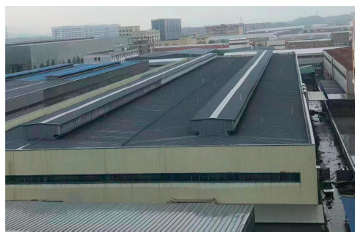
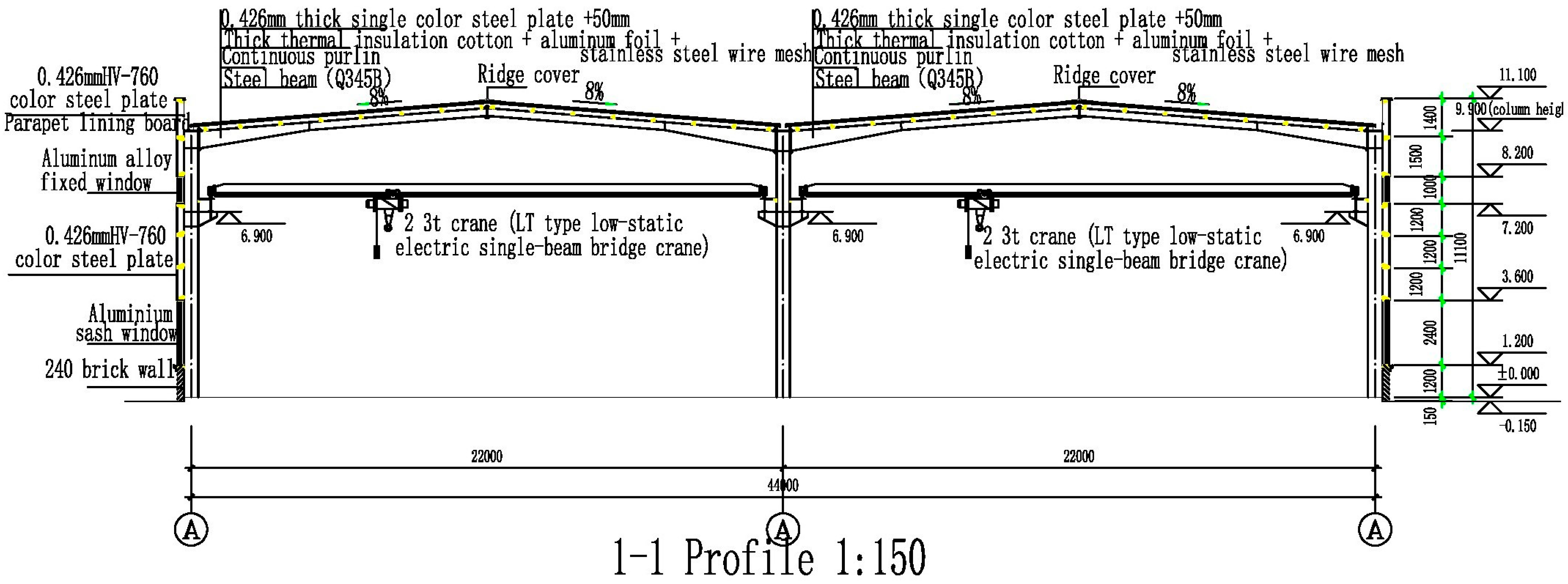
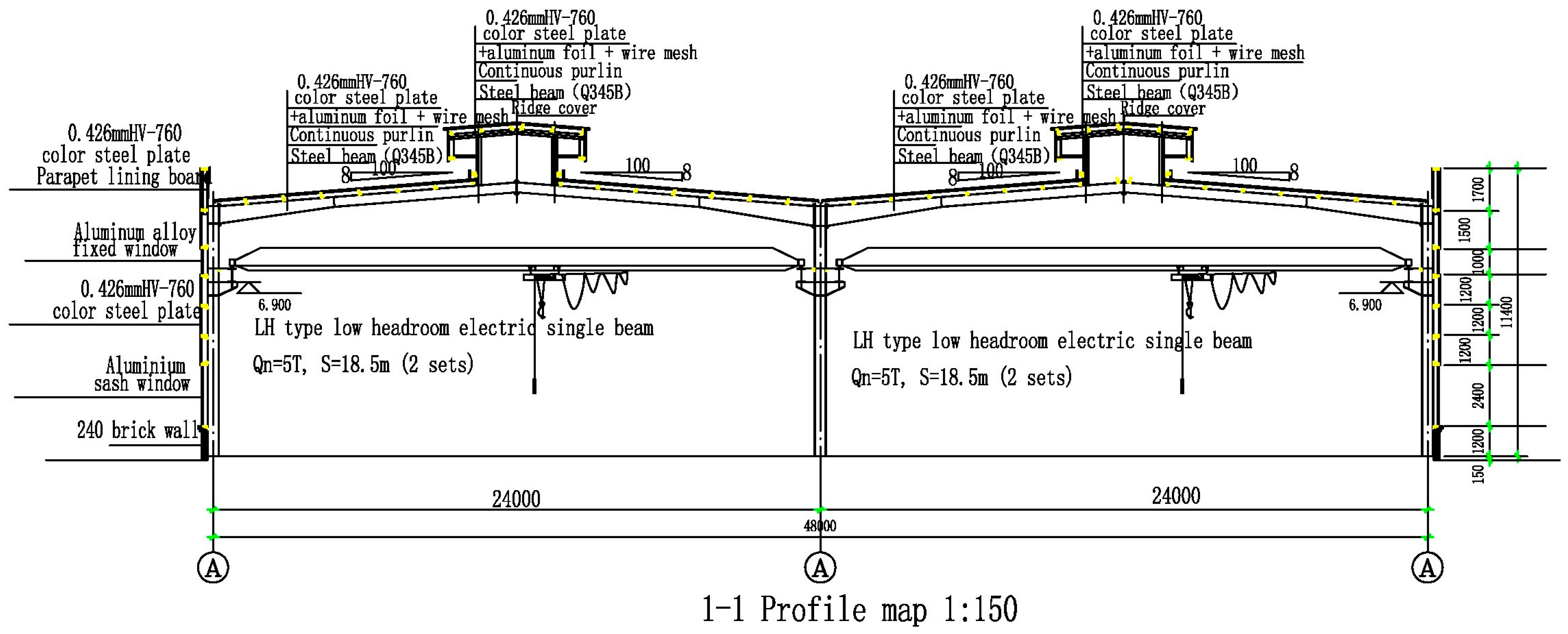
2. Project Profile
3. Reinforcing Analysis
3.1. Reinforcement Scheme
3.2. Reinforcement Mechanism
3.3. Computational Analysis and Modelling
- (1)
- (2)
- (3)
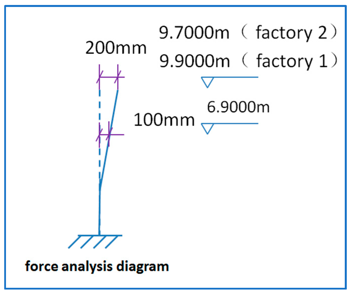
- Analysis of the upper part: The height of the column section is within the height range of 16.9–9.9 m. The original eccentricity of G1 is 400 mm, which has turned 100 mm to the right—a condition that is favourable to the upper end and ensures that no breakage occurs. The calculation is based on the GB 50009-2019 building structure loading code.
- (4)
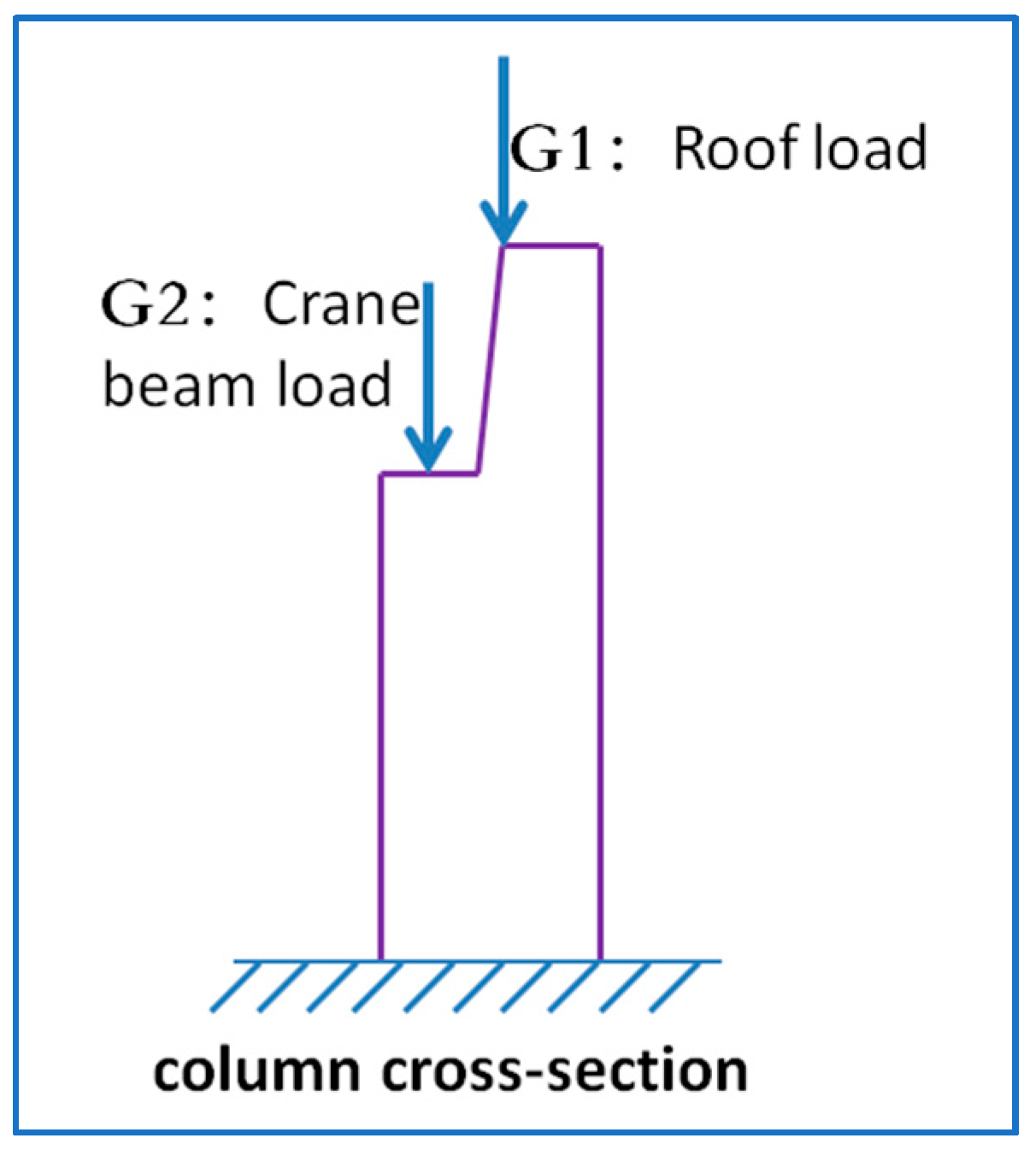
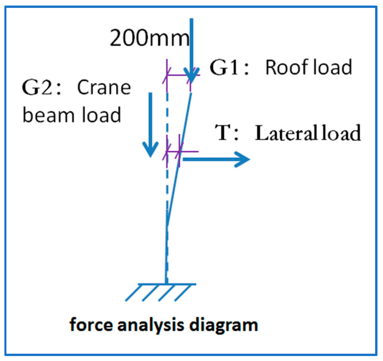
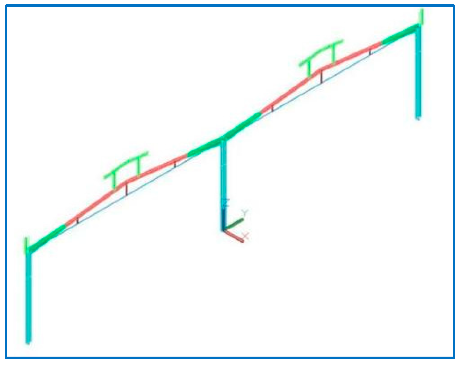
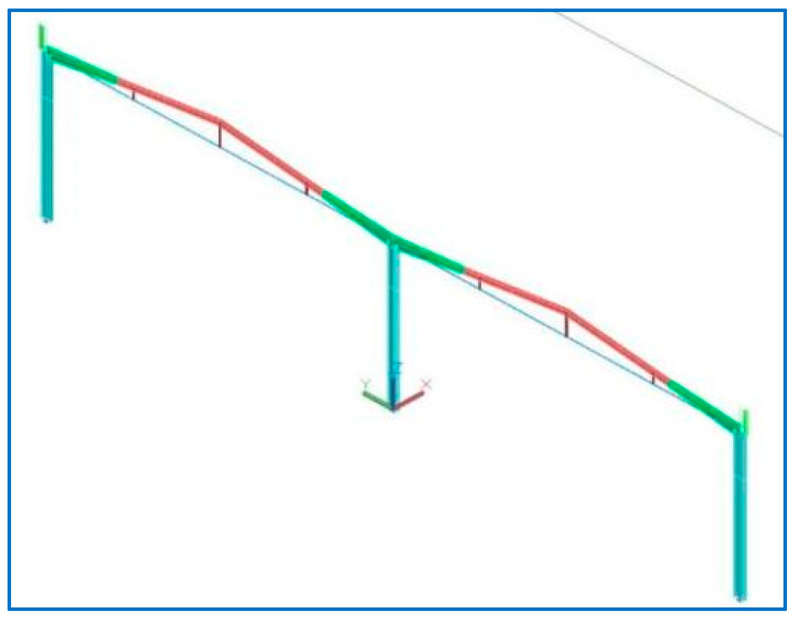
- Overall analysis (see Figure 9):G1: Original eccentricity + 0.3 (positive to the left)G2: original eccentricity − 0.5Deflection due to the column force:G1: original eccentricity = + 0.5G2: eccentricity becomes = −0.4Based on the calculation of a single piece of house truss in Powerhouse 1:
- 1)
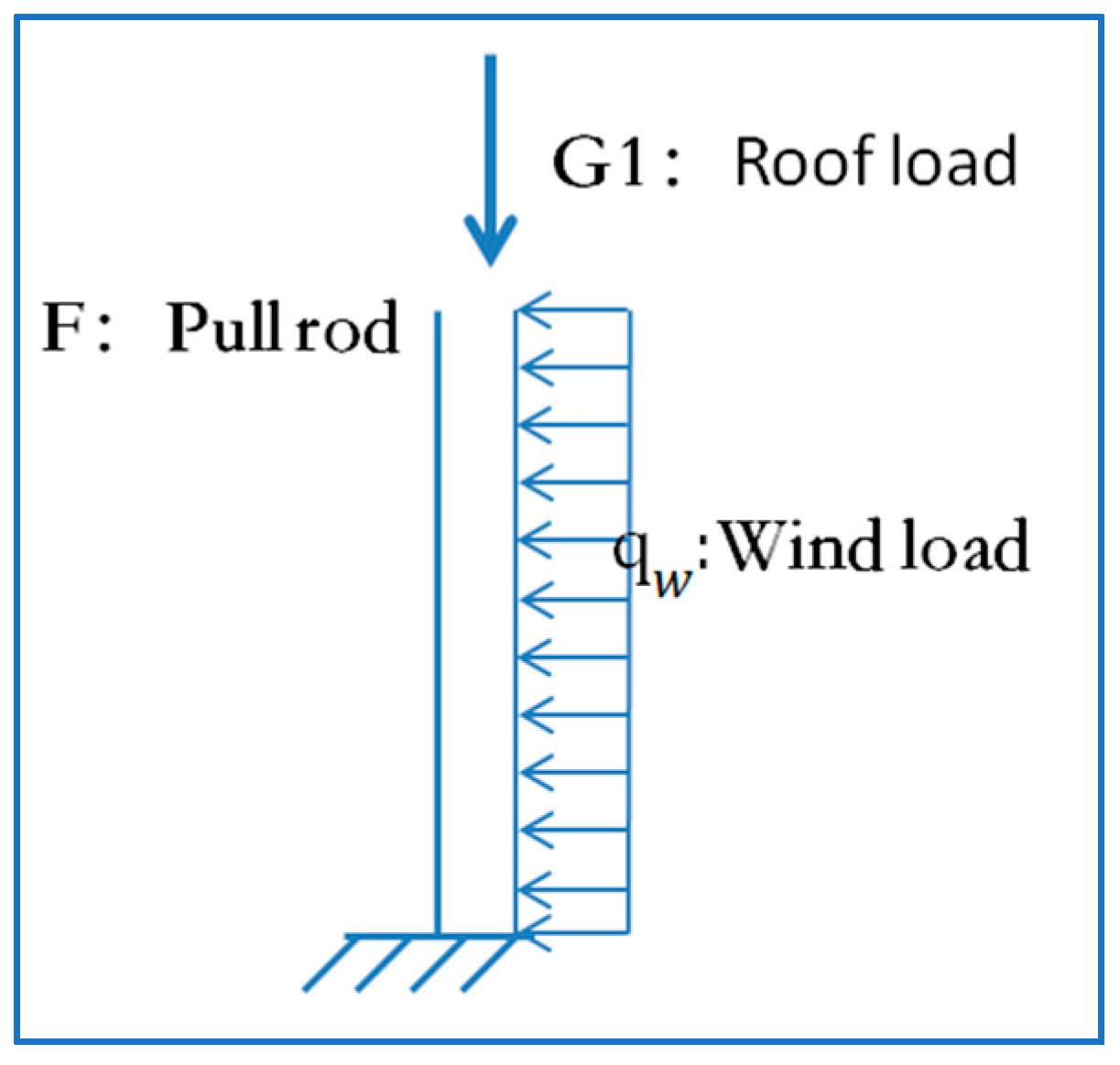
- Roof plate dead load: ; Live load: ;The span ranges from 22–24, with Seta pin spacing of 8
- 2)
- Wind load: Using simplified calculation, we take 1 as a uniform load, and then the line load is as follows:.
- 3)
- Vertical crane load (see Figure 10), because the eccentricity of the crane load is negative, the worst case is 0.
- 4)
- Dead weight of the wall:
- 5)
- The horizontal load (transverse) of the crane is two sets of soft hook crane A6 and heavy car.For the convenience of calculation, we considered the roof live load, according to the dead load, to meet the guaranteed rate. This includes the following:
- 6)
- Current situation: mm column bending capacity configuration: 10 HRB400 rebar with a diameter of 25 mm:
- 7)
- Horizontal tie-bar tension:
- (5)
3.3.1. Condition 1: Uniform Load
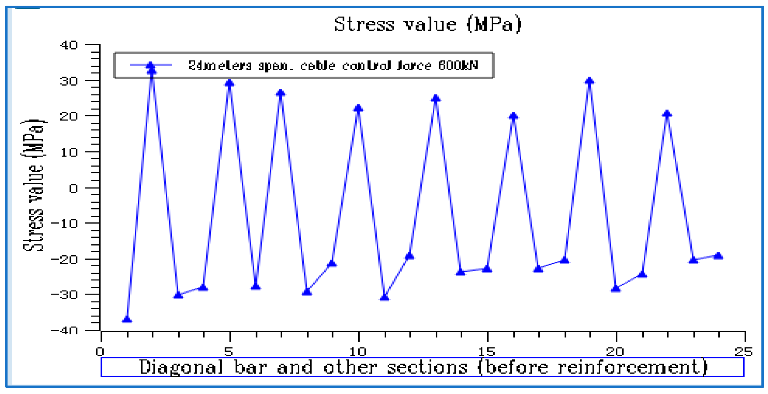
3.3.2. Condition 2: Stress Value
4. Nodal Analysis
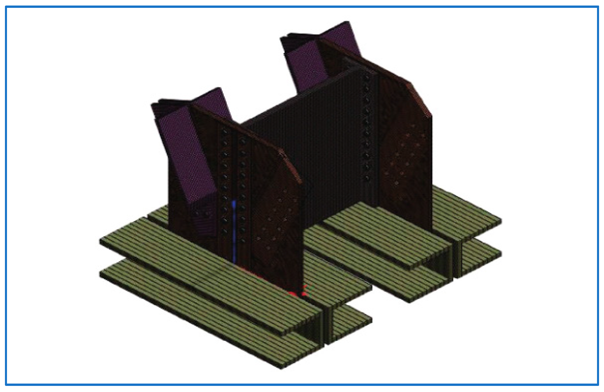
4.1. FE Modelling
4.2. Node Plate Analysis
5. Conclusions
- (1)
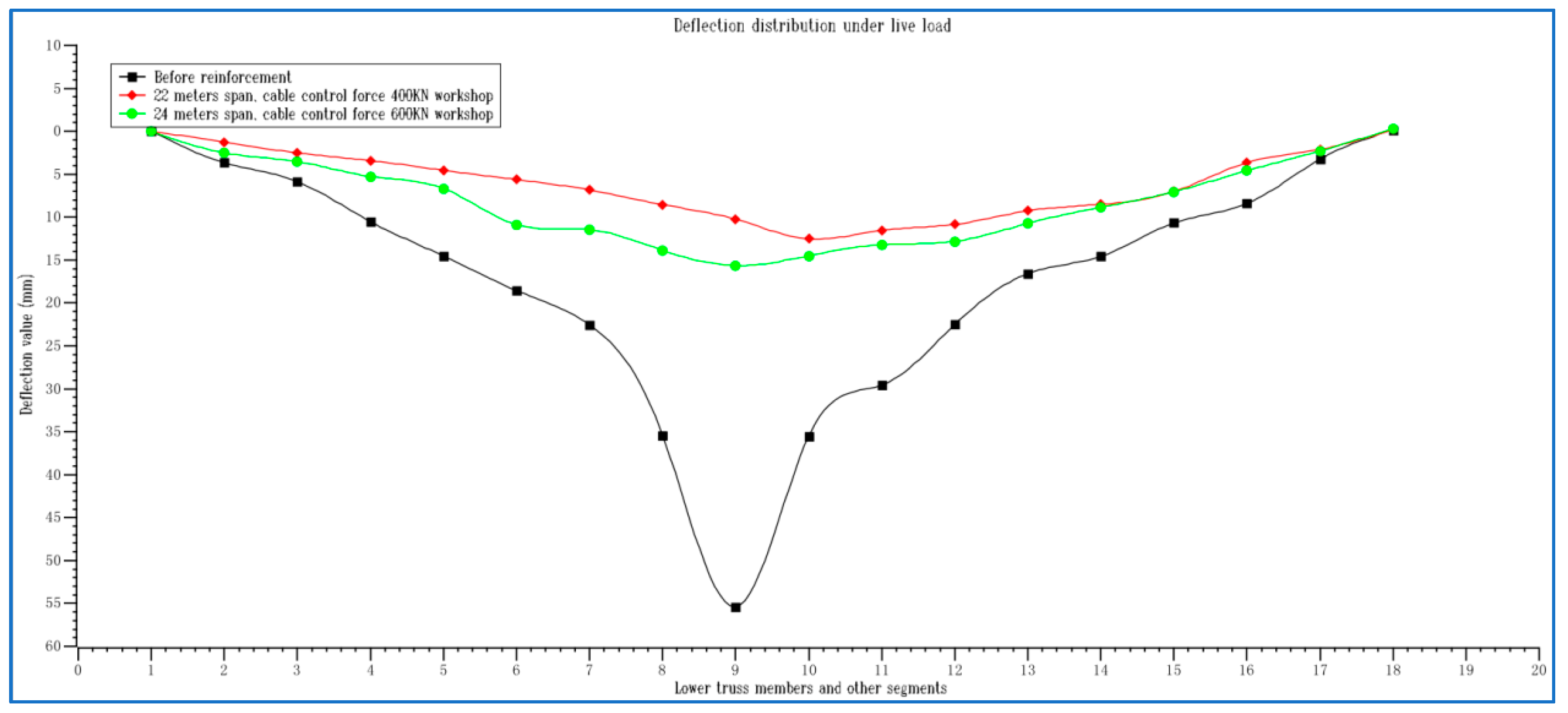
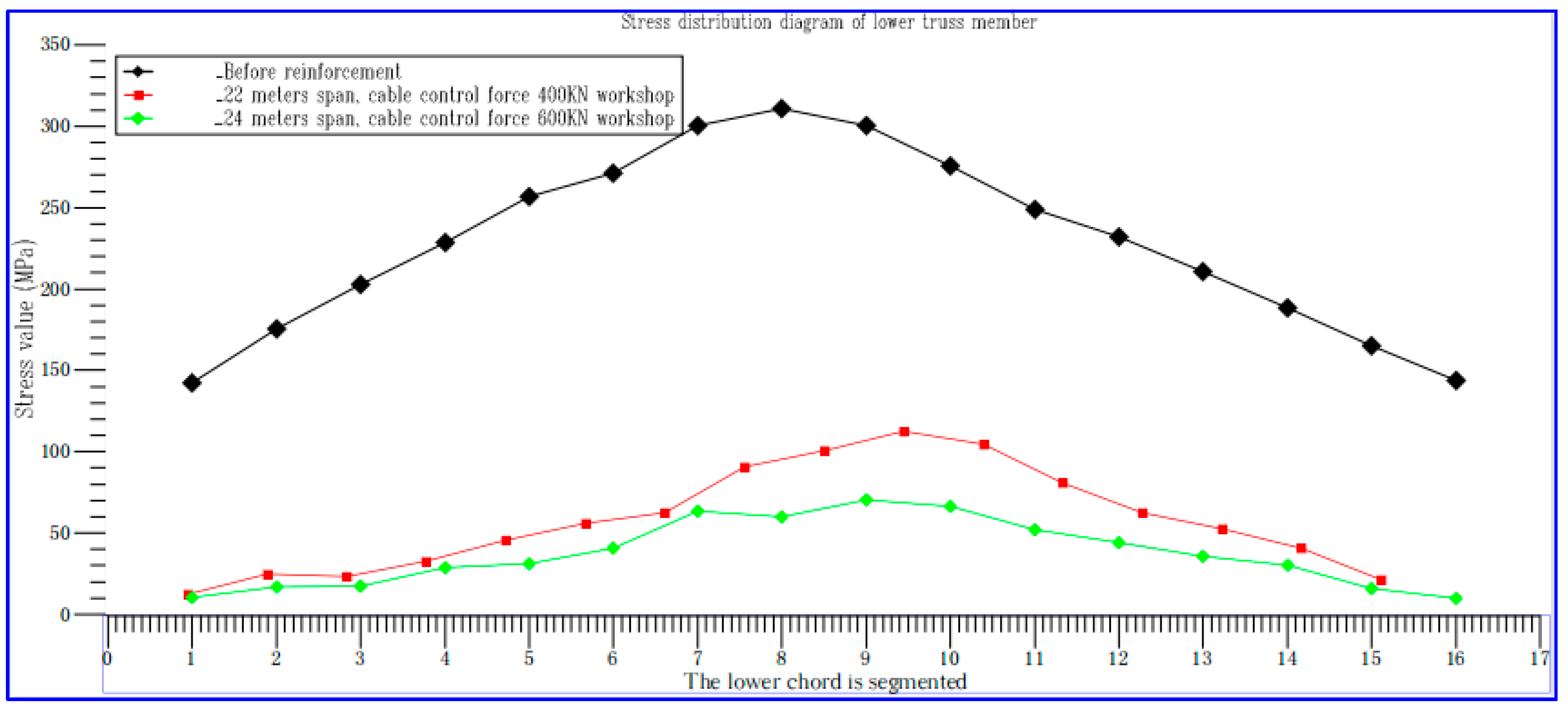
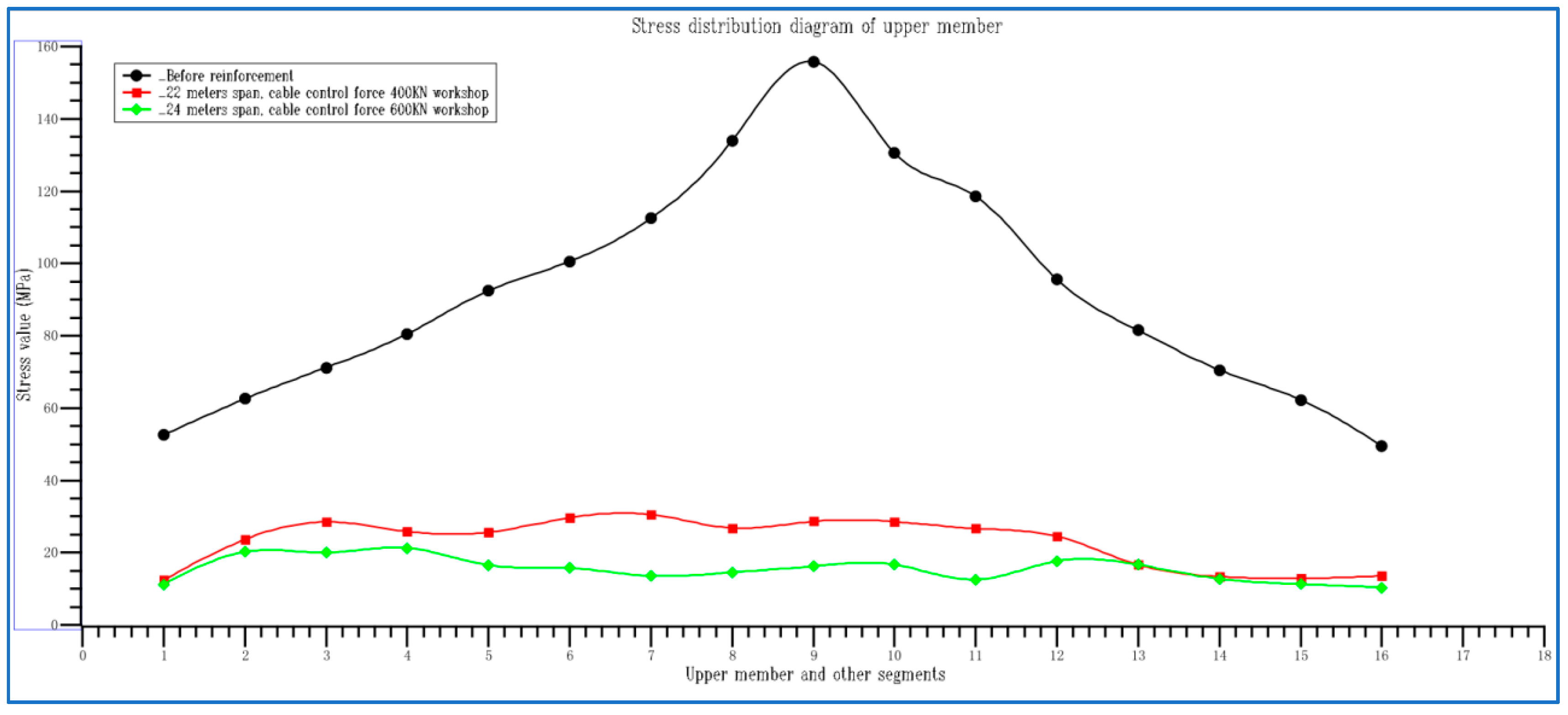
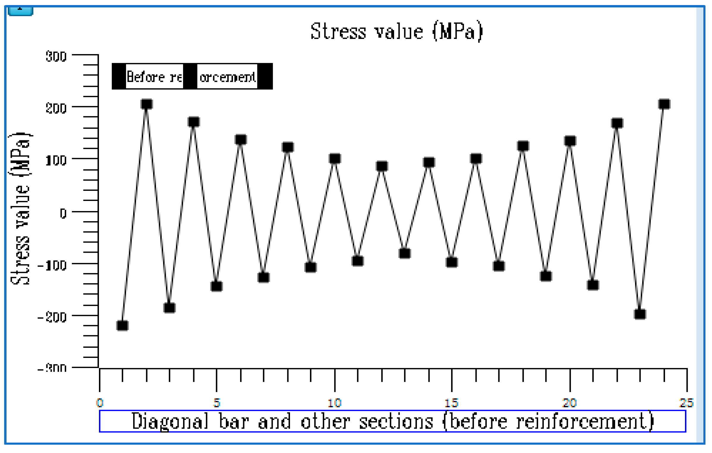
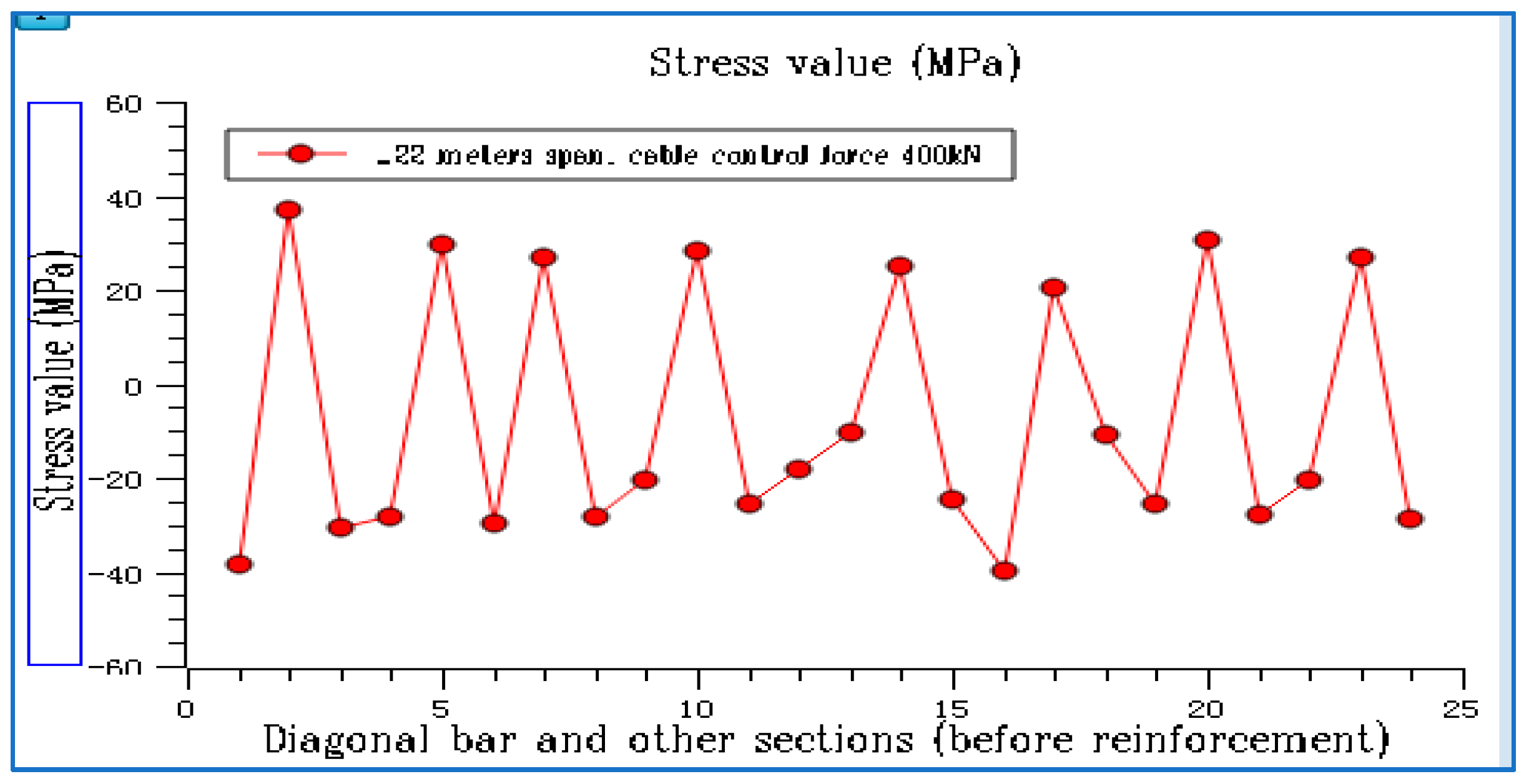
- After the cable reinforcement, the stiffness of the building truss increased, and the stress distribution trend of each component changed. Under the action of the crane and other main live loads, the reduction rate of the deflection value exceeded 50%. Furthermore, the maximum stress reduction rates of the upper and lower truss members exceeded 60%, whilst the overall load increase rates of the first and second powerhouse trusses exceeded 70% (Figure 11, Figure 12, Figure 13, Figure 14, Figure 15, Figure 16, Figure 17, Figure 18, Figure 19, Figure 20 and Figure 21) after being reinforced by the variable axial force cable.
- (2)
- Before reinforcement, the overall stress level of each node was reasonable, but this increased due to the increased load and service life limit after the installation of photovoltaic panels, along with the second-highest stress concentration at the bolt position of the node plate. After the reinforcement, the stress values of the node plates all decreased significantly. Moreover, the stress below 100 MPa accounted for over 90% of the nodes, whilst the higher stress accounted for less than 1% of the nodes (Table 1 and Table 2). The node plates after the reinforcement were in the stable stress area without tearing or stress damage.
- (3)
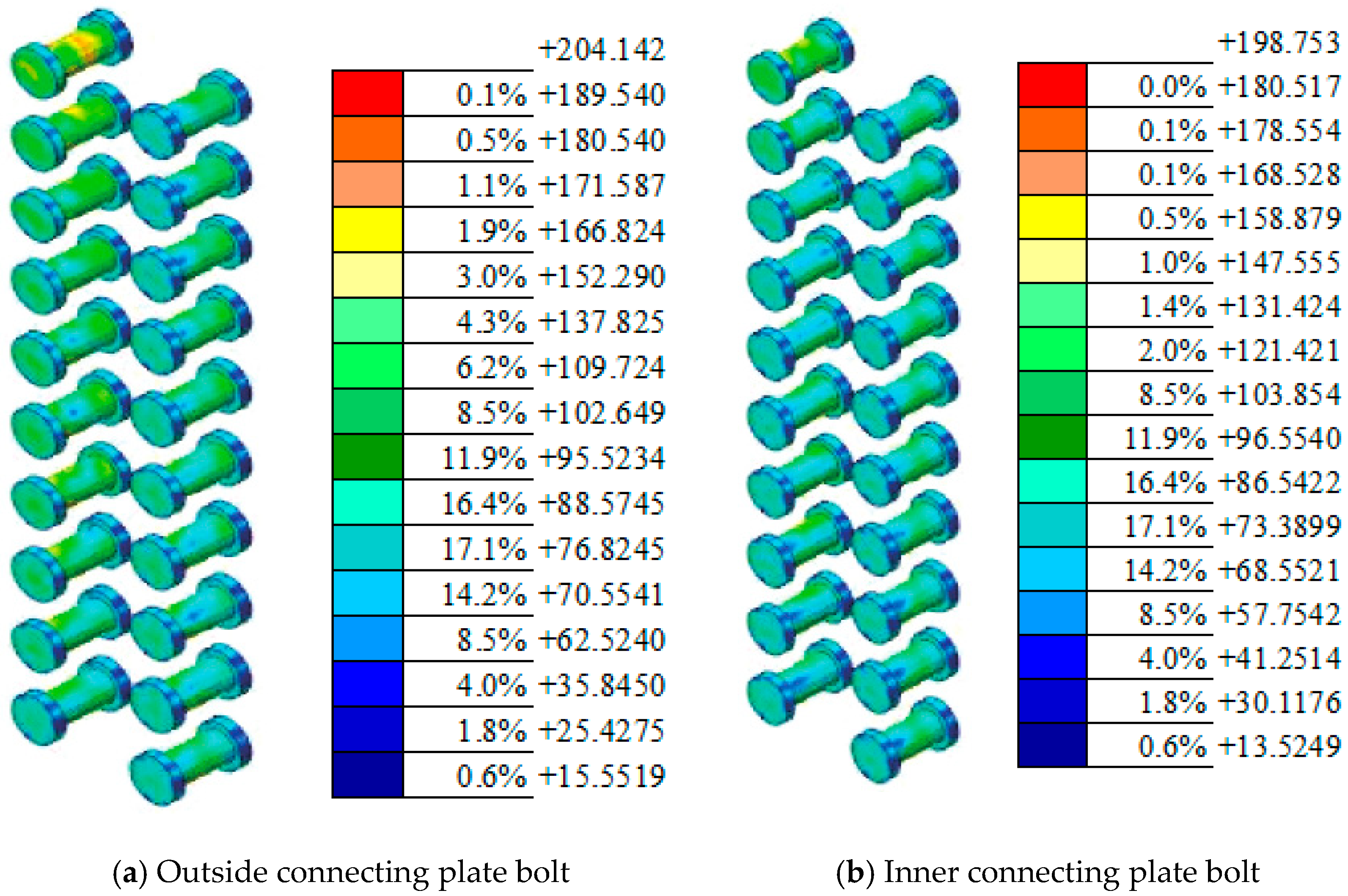
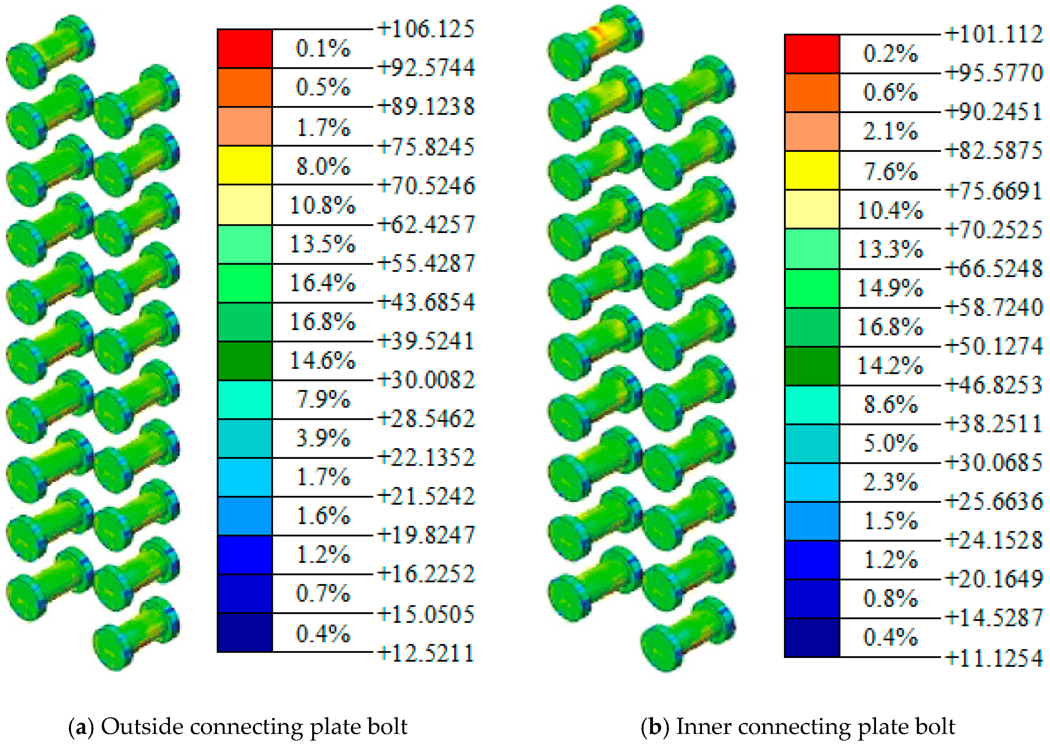
- The high-stress and secondary high-stress areas of the bolt group were mainly distributed near the load position. After the reinforcement, the stress zone area of 50–100 MPa accounted for about 35% of the bolt group, whilst the stress zone area above 100 MPa accounted for less than 1% (Table 3) TA. The problem of stress concentration has been solved, and the requirements of the new specification have been met.
Author Contributions
Funding
Conflicts of Interest
References
- Wang, X.; Yang, Y.; Xin, X.; Jia, J.; Xu, G.; Chen, Z. Computer Aided Design and Numerical Simulation of Dongming Yellow River Bridge Strengthened by a Cable-Stayed System. In Proceedings of the 2021 3rd International Conference on Artificial Intelligence and Advanced Manufacture, Manchester, UK, 23–25 October 2021; pp. 2625–2633. [Google Scholar]
- Cai, H.; Aref, A.J. On the design and optimization of hybrid carbon fiber reinforced polymer-steel cable system for cable-stayed bridges. Compos. Part B Eng. 2015, 68, 146–152. [Google Scholar] [CrossRef]
- Ceballos, M.A.; Prato, C.A. Determination of the axial force on stay cables accounting for their bending stiffness and rotational end restraints by free vibration tests. J. Sound Vib. 2008, 317, 127–141. [Google Scholar] [CrossRef]
- Simões, L.M.C.; Negrão, J.H.O. Sizing and geometry optimization of cable-stayed bridges. Comput. Struct. 1994, 52, 309–321. [Google Scholar] [CrossRef]
- Song, C.; Xiao, R.; Sun, B. Optimization of cable pre-tension forces in long-span cable-stayed bridges considering the counterweight. Eng. Struct. 2018, 172, 919–928. [Google Scholar] [CrossRef]
- Malekinejad, M.; Rahgozar, R. An analytical approach to free vibration analysis of multi-outrigger-belt truss-reinforced tall buildings. Struct. Des. Tall Spec. Build. 2013, 22, 382–398. [Google Scholar] [CrossRef]
- Khanorkar, A.; Sukhdeve, S.; Denge, S.V.; Raut, S.P. Outrigger and belt truss system for tall building to control deflection: A review. GRD J. Glob. Res. Dev. J. Eng. 2016, 1, 6–15. [Google Scholar]
- Qi, J.; Yang, H.C. Improvement of a truss-reinforced, half-concrete slab floor system for construction sustainability. Sustainability 2021, 13, 3731. [Google Scholar] [CrossRef]
- Hwang, J.S.; Lee, K.S. Seismic strengthening effects based on pseudodynamic testing of a reinforced concrete building retrofitted with a wire-woven bulk kagome truss damper. Shock. Vib. 2016, 2016, 1–17. [Google Scholar] [CrossRef]
- American Society of Civil Engineers. Minimum Design Loads and Associated Criteria for Buildings and Other Structures; American Society of Civil Engineers: New York, NY, USA, 2017. [Google Scholar]
- Hou, Z.; He, W.; Zhou, J.; Qiu, L. national standard «Code for acceptance of construction quality of steel structure engineering» GB50205 Introduction of special research results in revision. Stand. Eng. Constr. 2014, 49–55. [Google Scholar] [CrossRef]
- Keane, B.; Schwarz, G.; Thurnherr, P. Cables and cable glands for hazardous locations. In Proceedings of the 2018 IEEE Petroleum and Chemical Industry Technical Conference (PCIC), Cincinnati, OH, USA, 24–27 September 2018; Volume 42, p. 9. [Google Scholar]
- Revanna, N.; Moy, C.K.S.; Krevaikas, T. Verifying a Finite Element Analysis Methodology with Reinforced Concrete Beam Experiments; Research Press of America, Ed.; Research Press of America 2020 Paper Collection IV; Scientific Research Publishing: Chengdu, China, 2021; pp. 340–347. [Google Scholar]
- Teng, J.G.; Yu, T.; Fernando, D. Strengthening of steel structures with fiber-reinforced polymer composites. J. Constr. Steel Res. 2012, 78, 131–143. [Google Scholar] [CrossRef]
- Gardner, L. Stability and design of stainless steel structures—Review and outlook. Thin-Walled Struct. 2019, 141, 208–216. [Google Scholar] [CrossRef]
- Subramanian, N. Design of Steel Structures; Oxford University Press: Oxford, UK, 2008. [Google Scholar]
- Trahair, N.S.; Bradford, M.A.; Nethercot, D.A.; Gardner, L. The Behaviour and Design of Steel Structures to EC3; CRC Press: Boca Raton, FL, USA, 2017. [Google Scholar]
- Ban, H.; Shi, G. A review of research on high-strength steel structures. Proc. Inst. Civ. Eng. Struct. Build. 2018, 171, 625–641. [Google Scholar] [CrossRef]
- Marshall, J.D.; Jaiswal, K.; Gould, N.; Turner, F.; Lizundia, B.; Barnes, J.C. Post-earthquake building safety inspection: Lessons from the Canterbury, New Zealand, earthquakes. Earthq. Spectra 2013, 29, 1091–1107. [Google Scholar] [CrossRef]
- Bortolini, R.; Forcada, N. Building inspection system for evaluating the technical performance of existing buildings. J. Perform. Constr. Facil. 2018, 32, 04018073. [Google Scholar] [CrossRef]
- Ferraz, G.T.; De Brito, J.; De Freitas, V.P.; Silvestre, J.D. State-of-the-art review of building inspection systems. J. Perform. Constr. Facil. 2016, 30, 04016018. [Google Scholar] [CrossRef]
- Wen, J.; Liu, L.; Jiao, Q.; Yang, J.; Liu, Q.; Chen, L. Failure analysis on 20MnTiB steel high-strength bolts in steel structure. Eng. Fail. Anal. 2020, 118, 104820. [Google Scholar] [CrossRef]
- Caccese, V.; Mewer, R.; Vel, S.S. Detection of bolt load loss in hybrid composite/metal bolted connections. Eng. Struct. 2004, 26, 895–906. [Google Scholar] [CrossRef]
- Schauwecker, F.; Moncayo, D.; Middendorf, P. Characterization of high-strength bolts and the numerical representation method for an efficient crash analysis. Eng. Fail. Anal. 2022, 137, 106249. [Google Scholar] [CrossRef]
- Ahmad, F.; Bajpai, P.K. Evaluation of stiffness in a cellulose fiber reinforced epoxy laminates for structural applications:Experimental and finite element analysis. Def. Technol. 2018, 14, 278–286. [Google Scholar] [CrossRef]
- Jake, F.; Fidelis, M. Finite Element Analysis of Telecommunication Structure Reinforcement. ce/papers 2022, 5, 1084–1091. [Google Scholar] [CrossRef]
- Chhushyabaga, B.; Karki, S.; Khadka, S.S. Effect of Mechanical Vibration in a Power House Located in the Nepal Himalaya. In IOP Conference Series: Earth and Environmental Science; IOP Publishing: Bristol, UK, 2022; Volume 1037, p. 012065. [Google Scholar]
- Kiarasi, F.; Babaei, M.; Sarvi, P.; Asemi, K.; Hosseini, M.; Omidi Bidgoli, M. A review on functionally graded porous structures reinforced by graphene platelets. J. Comput. Appl. Mech. 2021, 52, 731–750. [Google Scholar]
- Lin, Y.H.; Lin, Z.H.; Chen, Q.T.; Lei, Y.P.; Fu, H.G. Laser in-situ synthesis of titanium matrix composite coating with TiB–Ti network-like structure reinforcement. Trans. Nonferrous Met. Soc. China 2019, 29, 1665–1676. [Google Scholar] [CrossRef]
- López, D.L.; Roca, P.; Liew, A.; Echenagucia, T.M.; Van Mele, T.; Block, P. A three-dimensional approach to the Extended Limit Analysis of Reinforced Masonry. In Structures; Elsevier: Amsterdam, The Netherlands, 2022; Volume 35, pp. 1062–1077. [Google Scholar]
- Koshcheev, A.A.; Roshchina, S.I.; Naichuk, A.Y.; Vatin, N.I. The effect of eccentricity on the strength characteristics of glued rods made of steel cable reinforcement in solid wood. In IOP Conference Series: Materials Science and Engineering; IOP Publishing: Bristol, UK, 2020; Volume 896, p. 012059. [Google Scholar]


| Span (m)/Control Force (kN) | Maximum Stress (MPa) | Stress Reduction (MPa) | Reduction Rate (%) |
|---|---|---|---|
| Before reinforcement | 310.82 | 0.0 | 0.0 |
| 22 m/400 kN | 112.52 | 212.54 | 65.38 |
| 24 m/600 kN | 70.54 | 244.70 | 77.62 |
| Component Name | Maximum Compressive Stress (MPa)/Position | Component Name | Maximum Compressive Stress (MPa)/Position | Reduced Value (MPa) |
|---|---|---|---|---|
| Reinforce the front inclined bar | 219/Near-truss | Reinforce the rear diagonal bar | 33.8/Near-truss | 185.2 |
| Reinforce the front mid-span diagonal bar | 73.5 | Reinforce the diagonal bar in the middle of the rear span | 38.2 | 34.6 |
| The rear inclined rod was reinforced with 22 m controlling force and 400 kN cable | 39.9 | The rear inclined rod was reinforced with a 24 m controlling force of 600 kN cable | 38.2 | 1.7 |
| Condition | Maximum Stress of the Connecting Plate Bolt (MPa) | The Stress Distribution Area above 100 MPa Accounted for (%) | The Stress Distribution Area between 50 and 100 MPa Accounted for (%) | The Stress Distribution Area below 50 MPa Accounted for (%) |
|---|---|---|---|---|
| Before reinforcement | 204 | 25.6 | 68.1 | 6.3 |
| After using 24 m of control force and 600 kN cable reinforcement | 106 | 0.1 | 34.6 | 65.3 |
Disclaimer/Publisher’s Note: The statements, opinions and data contained in all publications are solely those of the individual author(s) and contributor(s) and not of MDPI and/or the editor(s). MDPI and/or the editor(s) disclaim responsibility for any injury to people or property resulting from any ideas, methods, instructions or products referred to in the content. |
© 2023 by the authors. Licensee MDPI, Basel, Switzerland. This article is an open access article distributed under the terms and conditions of the Creative Commons Attribution (CC BY) license (https://creativecommons.org/licenses/by/4.0/).
Share and Cite
Shen, Z.; Hong, M.; Li, X.; Shen, Z.; Wang, L.; Wang, X. Application and Practice of Variable Axial Force Cable in Powerhouse Truss Reinforcement System. Buildings 2023, 13, 1271. https://doi.org/10.3390/buildings13051271
Shen Z, Hong M, Li X, Shen Z, Wang L, Wang X. Application and Practice of Variable Axial Force Cable in Powerhouse Truss Reinforcement System. Buildings. 2023; 13(5):1271. https://doi.org/10.3390/buildings13051271
Chicago/Turabian StyleShen, Zizhen, Min Hong, Xunfeng Li, Zigang Shen, Lianbo Wang, and Xueping Wang. 2023. "Application and Practice of Variable Axial Force Cable in Powerhouse Truss Reinforcement System" Buildings 13, no. 5: 1271. https://doi.org/10.3390/buildings13051271