Article

An Efficient Model for the Coupling Beam Using Damping Devices in Coupled Shear Wall Structures under Earthquake Loads

1
Faculty of Civil Engineering, Thuyloi University, 175 Tay Son, Dong Da, Hanoi 100000, Vietnam
2
Faculty of Civil Engineering, Electric Power University, 235 Hoang Quoc Viet, BacTuLiem, Hanoi 100000, Vietnam
3
Faculty of Civil Engineering, Mien Tay Construction University, 20B Pho Co Dieu, Vinh Long City 85000, Vietnam
*
Author to whom correspondence should be addressed.
Buildings 2023, 13(4), 941; https://doi.org/10.3390/buildings13040941
Submission received: 25 February 2023 / Revised: 22 March 2023 / Accepted: 31 March 2023 / Published: 2 April 2023
(This article belongs to the Special Issue Machine Learning Applications in Sustainable Buildings)

Abstract

:
This paper proposes a new element for modeling the energy-dissipation coupling beam to analyze the coupled shear wall structure under seismic loading. The new beam element includes 2 rigid beams and an energy dissipation device in the middle. The element stiffness matrix is derived based on principles of nonlinear mechanics. A procedure of the incremental-iterative solution is built using the Newmark method and adopted for solving the nonlinear equation of motion. A computer program using Matlab is developed to analyze the behavior of frame analogy which is modeled from the couped shear wall structure. Several numerical examples are presented to verify the developed program with the commercial finite element package SAP2000. The numerical results proved that the proposed program is efficient and reliable. The proposed element and program are then applied to analyze a 30-story coupled shear wall structure with energy dissipation devices. As a result, the locations of the device that provide effective seismic resistance for a 30-story coupled shear wall structure are in the region from the 5th to the 15th floor or assigned on all floors.

1. Introduction

High-rise buildings have been widely used for civil engineering thanks to the rapid development of both construction technology and computational techniques. The taller the building, the more sensitive it is to natural hazards such as earthquakes. Some major earthquake disasters can be mentioned as Skyline Plaza (Falls Church, VA, USA) in 1973, Royal Plaza Hotel (Nakhon Ratchasima, Thailand) in 1993, and Lotus Riverside Compound (Shanghai, China) in 2009, among others. Falling masonry or cladding, ceiling tiles dislodged, window frames separating from the walls, and toppling inwards or outwards are shown up numerous examples of risk from minor faults in construction under every earthquake. Once there is a loss of integrity in structural elements, mechanisms of overall or partial collapse can occur. Collapse can initiate at any level and may be due to lateral or torsional displacement, local failure of supporting members, excessive foundation movement, and occasionally the impact of another structure. As a result, the design and construction of high-rise buildings need to satisfy the stability and safety requirements under earthquakes [1].
To avoid associated uncertainties from an earthquake, special lateral load resisting systems has been used such as shear wall system [2], advanced bracing system (buckling restrained bracing system) [3], damper system (active damping [4], semi-active damping [5], and passive damping [6,7]), tubular systems (framed tubular system, braced tubular system, and bundled tubular system) [8,9,10,11,12]. A reinforced concrete shear wall system has been considered one of the most promising solutions due to its high stiffness and strength structural characteristics [13]. Windows and doors are openings that are perforated on structural walls and typically aligned, which create two or more walls coupled together by beams at each story level. Lateral loads are resisted in the coupled wall systems through a combination of cantilever actions in the individual wall piers. And the vertical loads are transferred through frame action in the coupling beam. When a building with a coupled shear wall system is under the attack of seismic forces, the coupling beams are deformed and thus excessive shear forces are induced [14]. It has been shown that the coupling beams are often damaged firstly in the coupled shear walls when an earthquake occurs, and this component is difficult to repair [15]. In addition, Paulay [16] showed that beams having a small span-depth ratio and conventional reinforced concrete structures are mostly susceptible to brittle failure. To improve the ductility of the beam, the use of diagonal reinforcement in the beam was proposed by Paulay and Binney [17]. This work illustrated that diagonal reinforced beams have a superior performance in hysteresis, diagonal shear resistance, and energy dissipation under cyclic loading. The main limitation of diagonal reinforcement in beams is the difficulty in placing and detailing the rebars. To overcome this drawback, many studies have been conducted to propose an appropriate reinforcement arrangement such as Tassios et al. [18], Galano and Vignoli [19], etc. Besides that, steel beams have been used thanks to the superior ductility and energy dissipation of steel material, for example, Harries et al. [20], Gong and Shahrooz [21], etc. To enhance the workability of steel beams, new steel beams have been developed by Fortney [22] and Pan and Weng [23] for adding a new device that is a central “fuse” where all failure and inelastic deformation are concentrated. Moreover, a lot of different types of energy dissipation devices have been applied in structures to reduce the earthquake-induced impact such as viscous dampers [24,25,26], friction dampers, metallic dampers [14], or combine metallic and viscous dampers [27], metallic damper and high-damping rubber materials [28,29].
Two types of modeling are considered for reinforced concrete coupled shear wall systems: (1) continuous medium method; (2) analogous frame method [2]. In the analogous frame model, which is applied in this study, the coupled shear wall consists of flexible columns at wall centroidal axes, flexible beams to represent the coupling beams, and rigid arms located at the connecting beam levels, spanning between the effective column and the external fibers [8]. This means when modeling the reinforced concrete coupled shear wall structures, the coupling beam consists of two rigid elements and one frame element. Recently, in addition to experimental studies, the coupling beam using the above types of energy dissipation devices is modeled including two rigid elements for the rigid area at the joints of wall piers and beams, coupling beam is modeled like a normal beam element, and zero-length element as dampers [23,30]. It is clear that the coupling beam model can be divided into 3 or 4 different elements in previous studies, however, the number of elements to be modeled as well as the computational volume is significantly large, especially for high-rise buildings. On the other hand, the purpose of this research is to combine the whole beam into 1 element, even in the case of coupling with or without energy dissipation device.
This paper introduces a new theoretical element model, namely the energy-dissipating coupling beam (EDCB) element, for the coupling beam with an energy dissipation device in the middle and having hysteresis behavior like the types of passive damping devices. The stiffness matrix of the EDCB element, which includes two rigid segments, a steel beam, and an energy dissipation device, is built based on the principle of nonlinear mechanics, using the first Engersser theorem. In addition, a Matlab program to analyze the coupled shear wall structure, using the analogous frame model, with the proposed element is developed. A 30-story building with double-wall structures is then studied to demonstrate the accuracy and robustness of the proposed coupling beam model. The investigation to find out the effective area for placing the device under the attack of seismic forces is also presented.

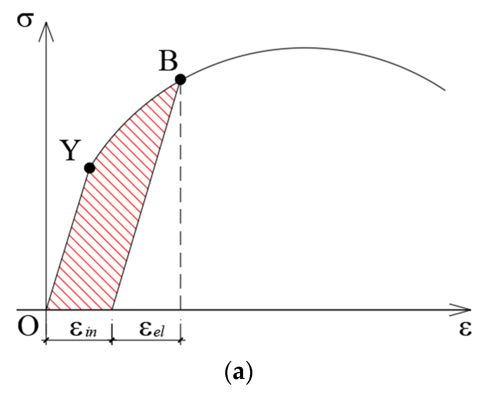
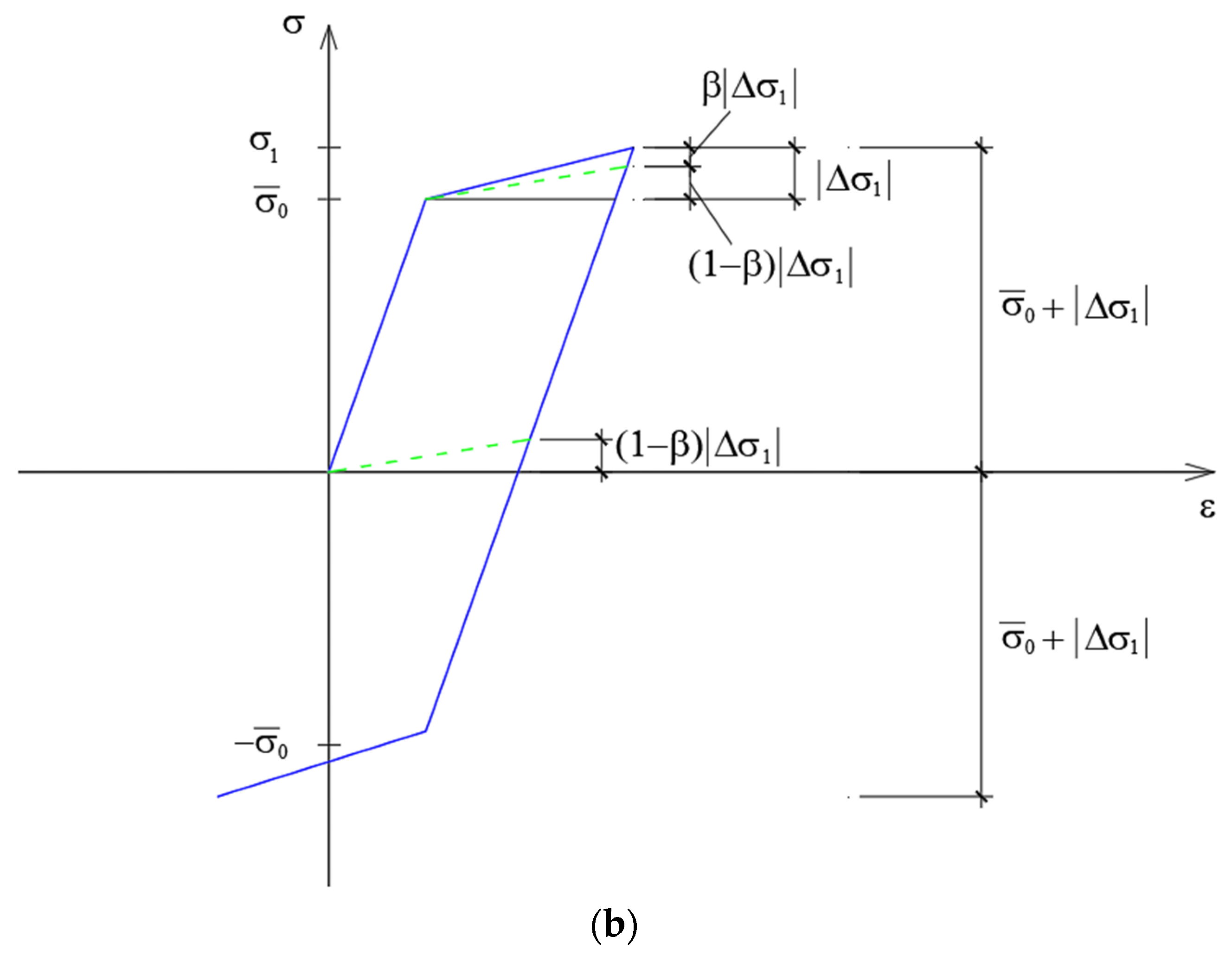
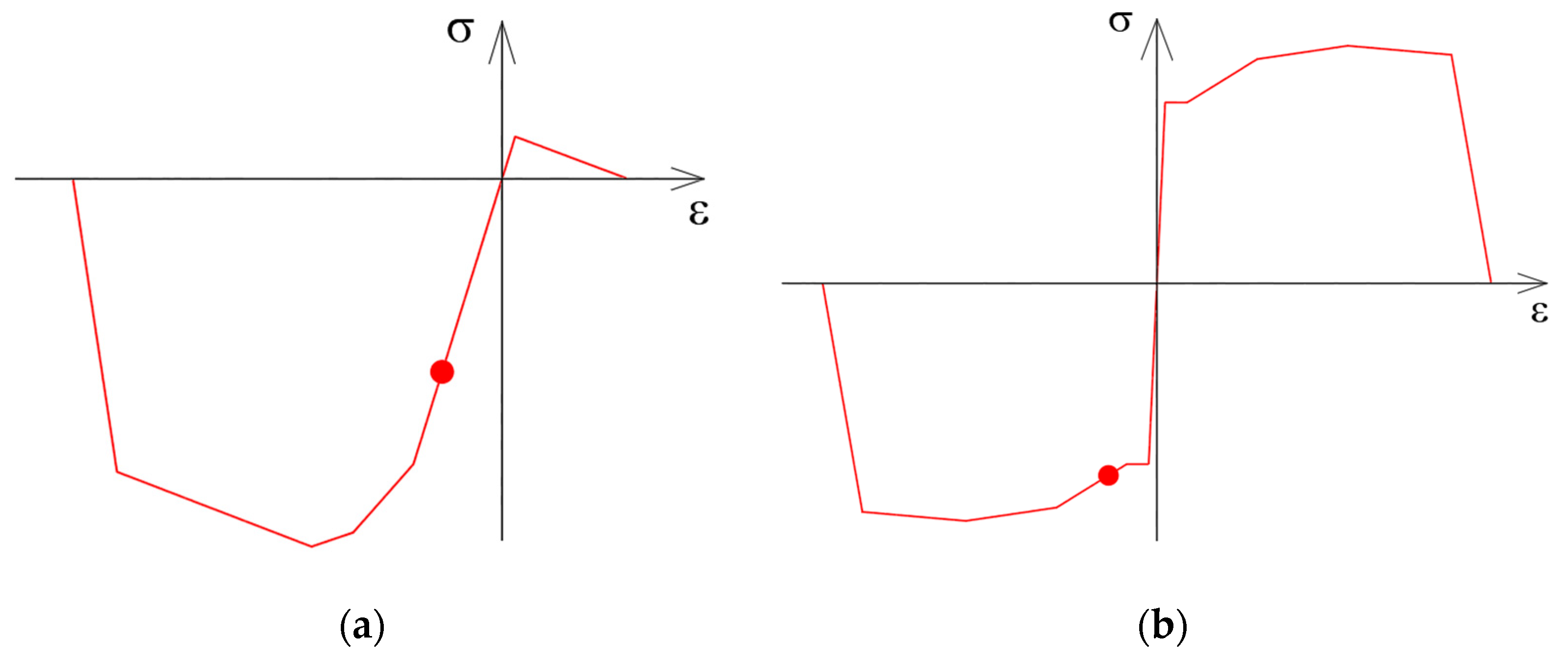
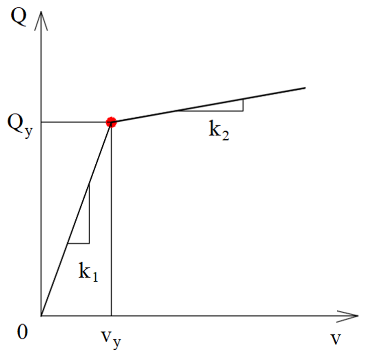
2. Constitutive Modeling

In this paper, the constitutive model of the metallic damper proposed by Soong and Dargush 1997 [31] is adopted to predict the inelastic deformation of the energy dissipation device as presented in Figure 1. Figure 1a shows the curve of characteristics for most metals. The response is fully elastic with σ n proportional to ε when the loads corresponding to nominal stress are less than the yield stress σ y . The initial state O, in this range, is fully recoverable when the applied load is removed, and no energy dissipation is there. On the other hand, when the nominal stress exceeds the yield stress, irreversible plastic deformation occurs dissipating energy. Considering the state labeled B, it is useful to partition the total strain at B into elastic ( ε e l ) and inelastic ( ε i n ) contributions.
Thus:
ε = ε e l + ε i n
In which:
ε e l = σ E
With E representing the elastic modulus. The nonlinear constitutive model accurately describes the practical response of most metals. However, it requires an advanced program for analysis that often takes too excessive computation cost. In this research, the bilinear model is applied with the material hardening law which is used kinematic hardening model proposed by Prager [32], details shown in Figure 1b and given by Nakashima [33] (where β is the strain–hardening parameter). An upper and lower limit stress of the kinematic hardening bound have absolute values the same and correspond to the maximum stress experienced in the previous loading history [34]. For other structural components, concrete and steel constitutive models used Takeda and Kinematic hysteresis rules [35,36], respectively, as shown in Figure 2.

3. Beams and Columns Modeling

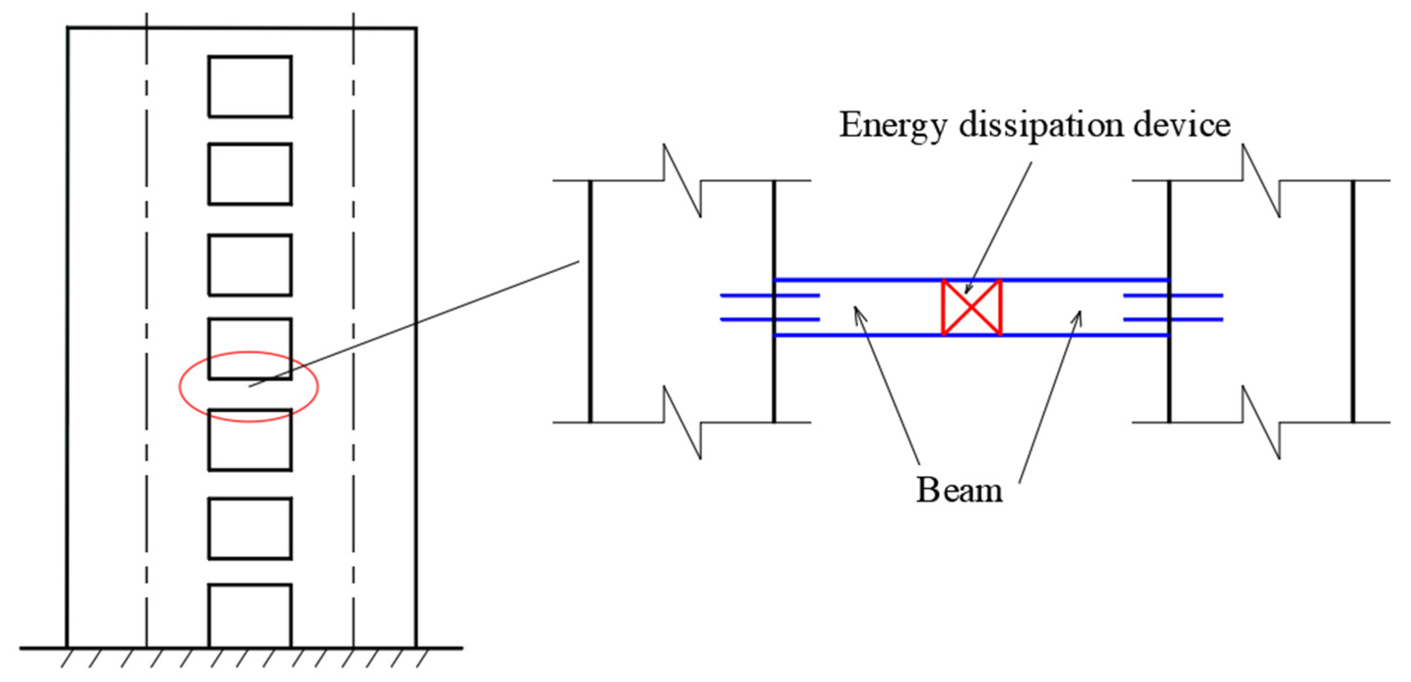
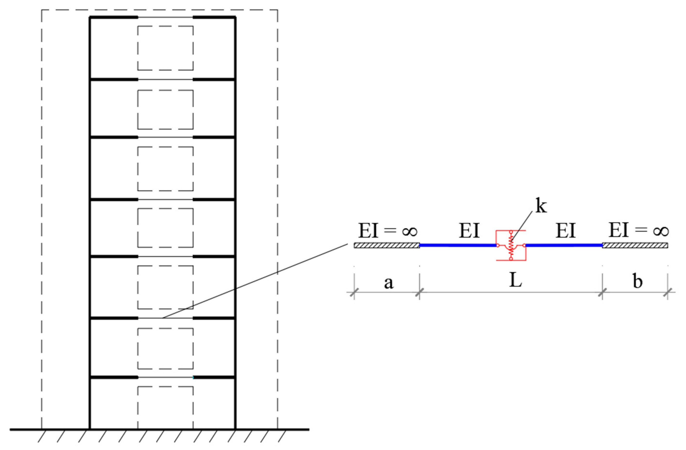
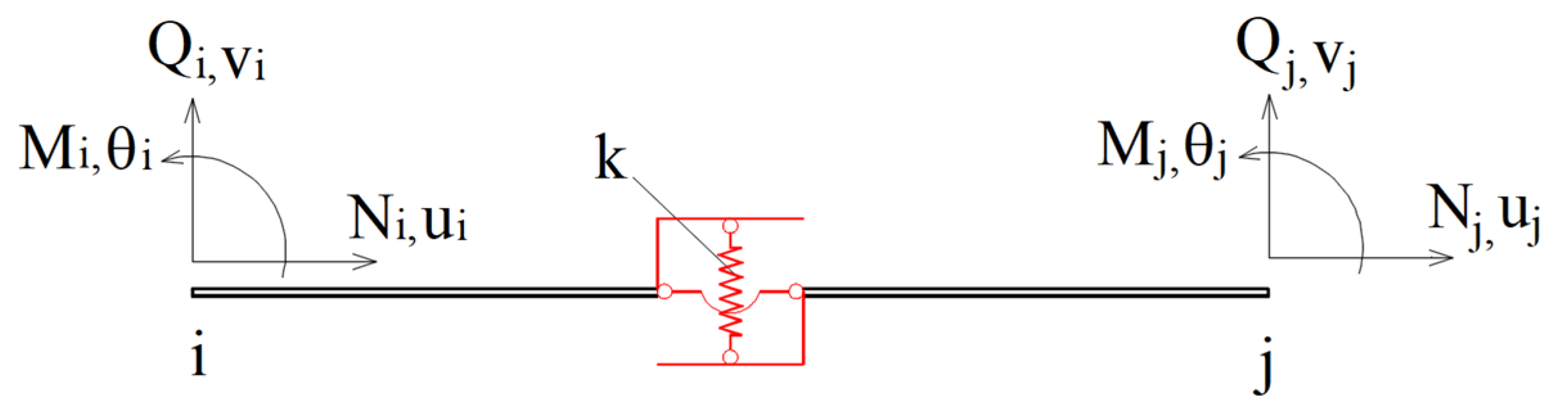
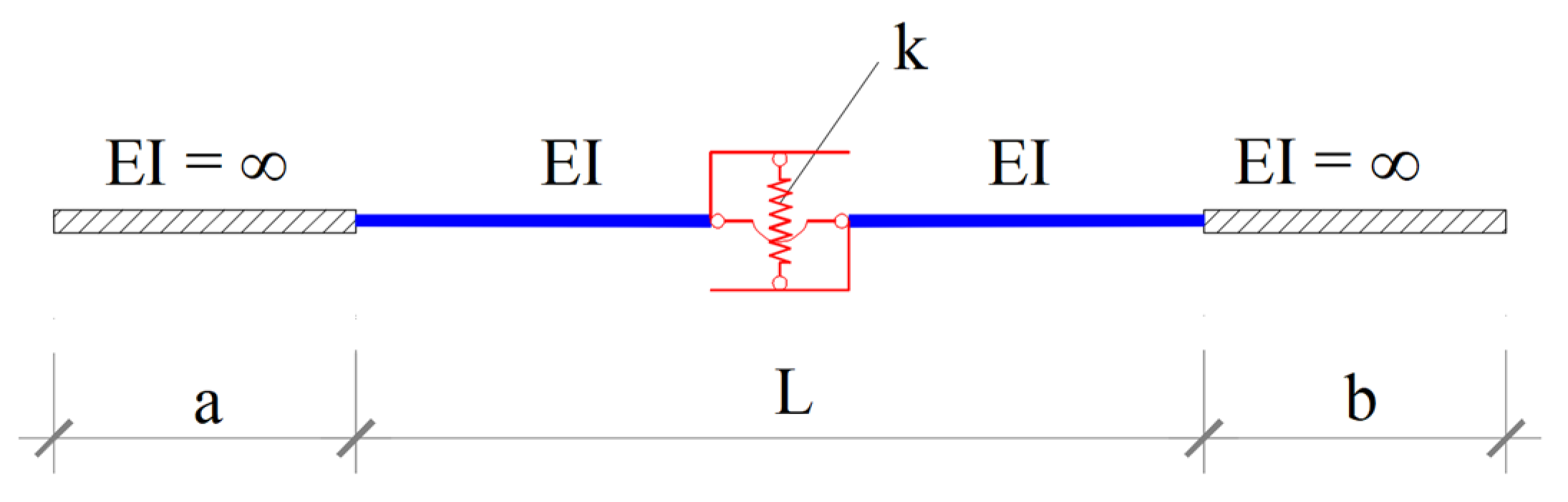
3.1. Energy-Dissipating Coupling Beam Element Stiffness Matrix

Recently, reinforced concrete coupling beams have gradually changed by steel beams due to their many advantages such as being able to be replaced or repaired after suffering an earthquake and being easily installed. Figure 3 shows a coupling beam, which is composed of a steel beam working in the elastic region and an energy dissipation device placed in its middle to dissipate energy caused by earthquakes and prevent serious structural damage. The construction of the structure can use a plan of walls on both sides (Figure 4) connected by coupling beams using bolts at high elevations.
In light of the above discussion, in this section, a beam element with an energy dissipation device, namely the energy-dissipating coupling beam (EDCB) element, is developed that can withstand the deviation between two walls in a coupled shear wall, and at the same time can dissipate the energy of the building under the impact of an earthquake. The model of an EDCB element is described in Figure 5. Because the equivalent wide-column frame model is used to analyze the coupled shear wall, the structure of the beam element includes 2 absolutely rigid beams (a and b in length), the coupling beam which is the length of L is composed of: energy dissipation device (capable of vertical sliding and no horizontal displacement) in the middle and a steel beam.
To build the stiffness matrix of the EDCB element, the stiffness matrix of the beam element, which is the coupling beam including the energy dissipation device as shown in Figure 6, is developed first. Then, this matrix is converted from the local coordinate system to the global coordinate system to analyze the structure. The stiffness matrix of the EDCB element is built as the following based on the principle of nonlinear mechanics, using the first Engersser theorem.
Considering a beam element with an energy dissipation device in the middle that has the device stiffness coefficient k as shown in Figure 6. Each end of the member is considered using three degrees of freedom (two vertical and horizontal displacements, one rotation). Therefore, the member has six possible degrees of freedom, and the resulting stiffness matrix is of order 6 × 6. The positive direction of vertical, horizontal, and rotational displacements is specified as positive as shown in Figure 6. The elements of the stiffness matrix represent the forces acting on the member by the restraints at the ends of the member when unit displacements are applied at each end of the member.
In Figure 6, bending moments and corresponding rotations are M i , j and θ i , j at ends i and j, respectively; axial forces and corresponding axial deformations are N i , j and u i , j at ends i and j, respectively; shear forces and corresponding transverse displacements are Q i , j and v i , j at ends i and j, respectively. The steel beam is assumed linear elastic while energy dissipation devices have nonlinear behavior Q = k ( v ) v (k > 0) (Figure 7).
The stiffness matrix [K] is constructed based on the equilibrium and compatibility conditions between the members. For a general frame, the equilibrium matrix equation of a member is:
{ N i Q i M i N j Q j M j } = [ K 11 0 0 K 14 0 0 0 K 22 K 23 0 K 25 K 26 0 K 32 K 33 0 K 35 K 36 K 41 0 0 K 44 0 0 0 K 52 K 53 0 K 55 K 56 0 K 62 K 63 0 K 65 K 66 ] { u i v i θ i u j v j θ j } { P } = [ K e ] { d }
where: {P} is the member force vector; [Ke] is the member stiffness matrix; and {d} is the member displacement vector, all in the member’s local coordinate system.
The element stiffness matrix in the local coordinate system is established from the problem of axial loading, bending moments, and shear.
  • Axial loading:
The energy dissipation device only affects to bending moment and shear of the EDCB element, but without any impact on axial loading. Hence:
K 11 = K 14 = K 41 = K 44 = E A L
where: A is the cross-sectional area and L is the length of the member.
  • Bending moments and shear:
When unit displacements are imposed at each end of the member, the elements of the stiffness matrix indicate forces exerted on the member by the restraints at the ends of the member. When unit displacement is imposed along each degree of freedom holding all other displacements to zero, let us calculate the forces developed in the above member.
-
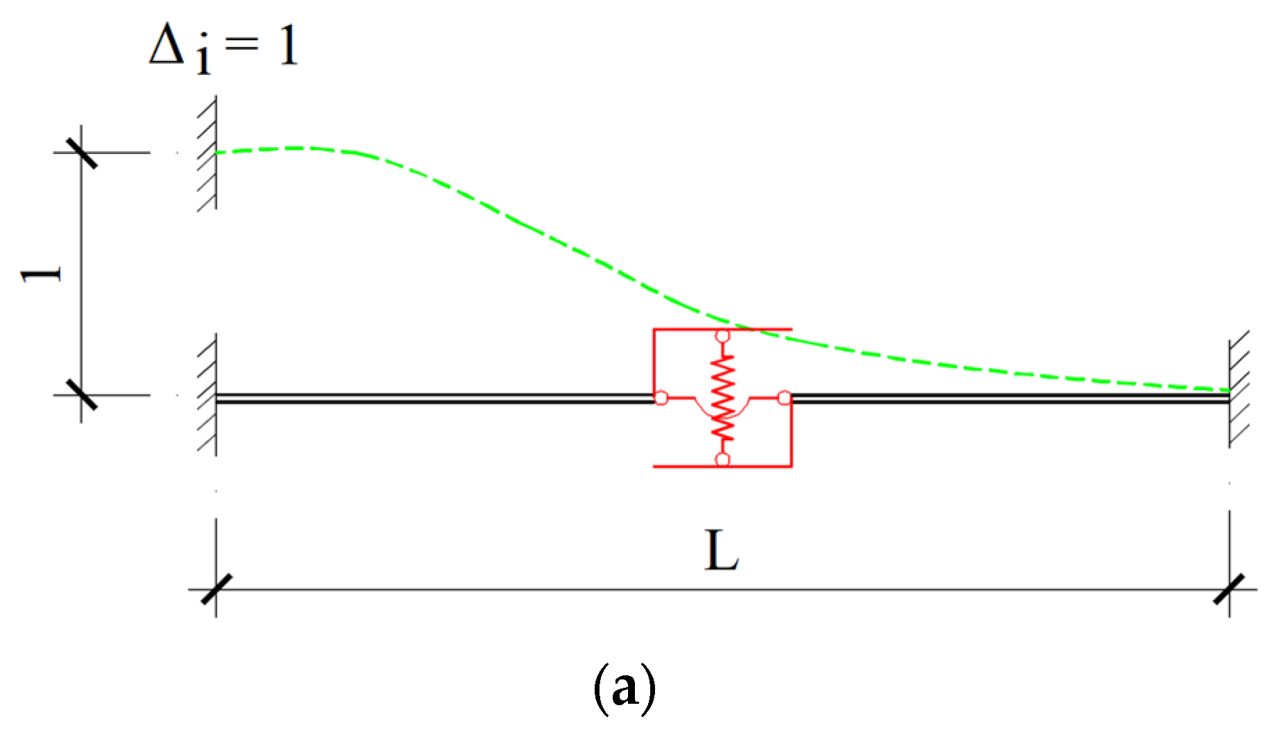
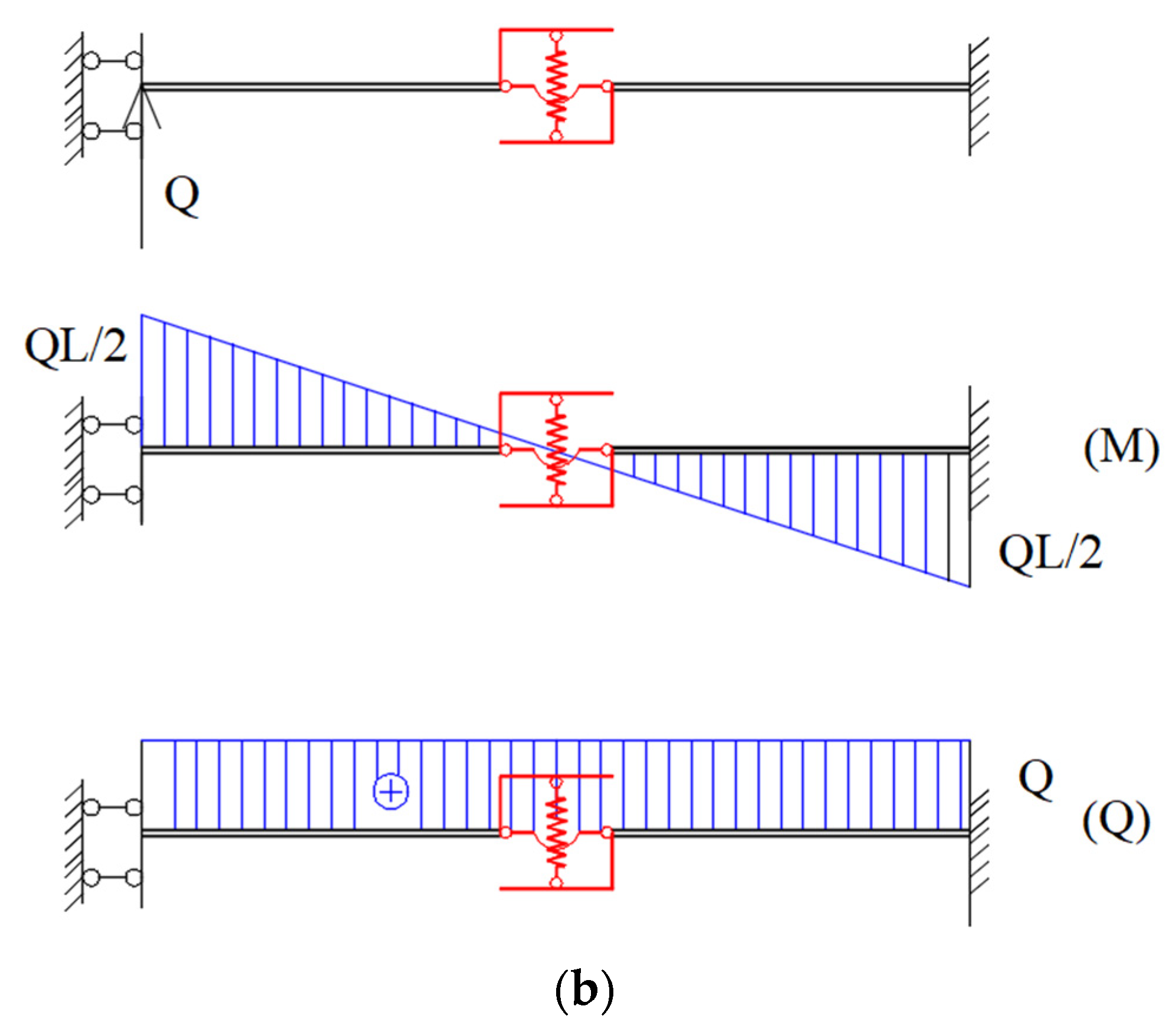
Case 1: Now impose a unit displacement at the i-end of the member while holding all other displacements to zero (Δi = 1) (Figure 8).
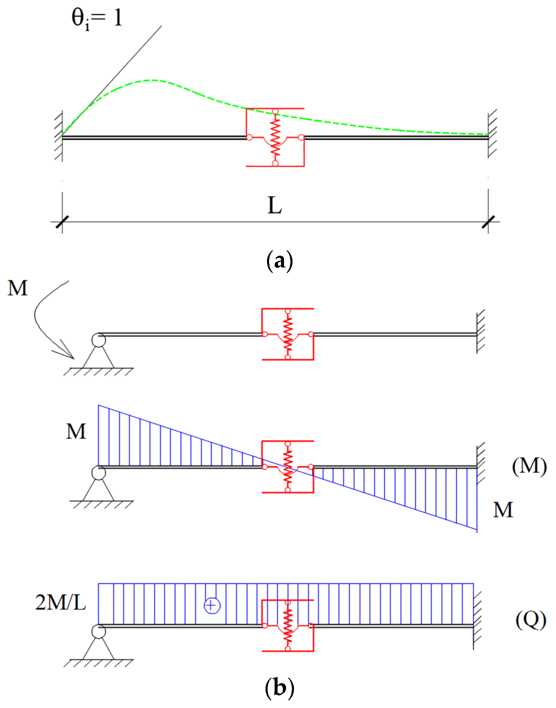
Application of Engesser’s 1st theorem [37], the complementary strain energy for a member is calculated as
U * = 2 0 L / 2 M ( x ) 2 d x 2 E I + 0 Q v d Q = 2 0 L / 2 ( Q x Q L 2 ) 2 d x 2 E I + 0 Q v d Q
Δ = U * Q = 2 0 L / 2 2 Q · ( x L 2 ) 2 d x 2 E I + v = Q · L 3 12 E I + Q k
By applying Δ = 1 , we have
Q = k k + 12 E I L 3 · 12 E I L 3 = χ · 12 E I L 3
where: χ = 1 1 + 12 E I k L 3 . The shear force is constant in the entire beam, thus: Q i = Q , Q j = Q i = Q . Due to the fact that the energy dissipation device is assigned in the middle of the coupling beam, so: M i = M j = Q i L 2 . Hence:
[ Q i M i Q j M j ] = [ Q 22 M 32 Q 52 M 62 ] = [ χ 12 E I L 3 χ 6 E I L 2 χ 12 E I L 3 χ 6 E I L 2 ]
-
Case 2: unit rotation at ii = 1) (Figure 9)
Unit rotation is imposed at the i end of the beam while holding all other displacements to zero.
Application of Engesser’s 1st theorem, the complementary strain energy for a member:
U * = 2 0 L / 2 M ( x ) 2 d x 2 E I + 0 Q v d Q = 2 0 L / 2 ( 2 M L x M ) 2 d x 2 E I + 0 M v d 2 M L
θ = U * M = 2 0 L / 2 2 M ( 2 L x 1 ) 2 d x 2 E I + 2 L · v = M L 3 E I + 4 M k L 2
Hence: θ = 1
M = k k + 12 E I L 3 · 3 E I L = χ · 3 E I L
This means M i = M j = M . The shear force is constant in the entire beam, thus we have: Q i = 2 M i L , Q j = Q i . Hence:
[ Q i M i Q j M j ] = [ Q 23 M 33 Q 53 M 63 ] = [ χ 6 E I L 2 χ · 3 E I L χ 6 E I L 2 χ · 3 E I L ]
Similarly, unit displacement and unit rotation at the j end is imposed and corresponding stiffness coefficients are calculated. Hence, the stiffness matrix of the element when subjected to bending with the energy dissipation device attached to the local coordinate system is shown as follows:
[ K e ] b e n d i n g = [ χ 12 E I L 3 χ 6 E I L 2 χ 12 E I L 3 χ 6 E I L 2 χ 6 E I L 2 χ · 3 E I L χ · 6 E I L 2 χ · 3 E I L χ 12 E I L 3 χ 6 E I L 2 χ 12 E I L 3 χ 6 E I L 2 χ 6 E I L 2 χ · 3 E I L χ · 6 E I L 2 χ · 3 E I L ]
In general, the shear strain is usually very small and is ignored when calculating the beam element. However, for beams with a small span-to-height ratio, shear strain must be taken into account. With the Euler-Bernoulli beam theory, also known as the classical beam theory, the beam element has a stiffness matrix (13). Meanwhile, according to Timoshenko beam theory, when taking into account the influence of shear strain, the stiffness matrix (13) needs to be adjusted [38].
Therefore, the stiffness matrix of the EDCB element, taking into account the effect of shear strain, has the form:
[ K e ] = [ E A L 0 0 E A L 0 0 0 χ 12 E I L 3 ( 1 + Φ ) χ 6 E I L 2 ( 1 + Φ ) 0 χ 12 E I L 3 ( 1 + Φ ) χ 6 E I L 2 ( 1 + Φ ) 0 χ 6 E I L 2 ( 1 + Φ ) χ · 3 E I L ( 1 + Φ ) 0 χ · 6 E I L 2 ( 1 + Φ ) χ · 3 E I L ( 1 + Φ ) E A L 0 0 E A L 0 0 0 χ 12 E I L 3 ( 1 + Φ ) χ 6 E I L 2 ( 1 + Φ ) 0 χ 12 E I L 3 ( 1 + Φ ) χ 6 E I L 2 ( 1 + Φ ) 0 χ 6 E I L 2 ( 1 + Φ ) χ · 3 E I L ( 1 + Φ ) 0 χ · 6 E I L 2 ( 1 + Φ ) χ · 3 E I L ( 1 + Φ ) ]
Note that: I is second-moment inertia; G is shear modulus; ν is Poission’s ratio; Φ = 12 E I L 2 κ G A ; and κ = 10 ( 1 + ν ) 12 + 11 ν .
Determination of the stiffness matrix of the beam with rigid zones at ends, whose lengths are a (left) and b (right) as presented in Figure 10, respectively.
The transformation matrix is:
[ e ] = [ 1 0 0 0 0 0 0 1 a 0 0 0 0 0 1 0 0 0 0 0 0 1 0 0 0 0 0 0 1 b 0 0 0 0 0 1 ]
The stiffness matrix for the beam-attached energy dissipation device with rigid zones can be related to the stiffness matrix of the beam without rigid zones, through the congruent transformations, that is:
[ K ] = [ e ] T [ K e ] [ e ]

3.2. Beam–Column Element Stiffness Matrix

According to Timoshenko beam theory, the stiffness matrix of the column and coupling beam without energy dissipation device has the form [39]:
[ K l ] = [ E A L 0 0 E A L 0 0 0 12 E I L 3 ( 1 + Φ ) 6 E I L 2 ( 1 + Φ ) 0 12 E I L 3 ( 1 + Φ ) 6 E I L 2 ( 1 + Φ ) 0 6 E I L 2 ( 1 + Φ ) ( 4 + Φ ) E I L ( 1 + Φ ) 0 6 E I L 2 ( 1 + Φ ) ( 2 Φ ) E I L ( 1 + Φ ) E A L 0 0 E A L 0 0 0 12 E I L 3 ( 1 + Φ ) 6 E I L 2 ( 1 + Φ ) 0 12 E I L 3 ( 1 + Φ ) 6 E I L 2 ( 1 + Φ ) 0 6 E I L 2 ( 1 + Φ ) ( 2 Φ ) E I L ( 1 + Φ ) 0 6 E I L 2 ( 1 + Φ ) ( 4 + Φ ) E I L ( 1 + Φ ) ]

4. Solution Algorithm

4.1. Static Analysis

For static structural analysis, the displacement { u } is solved using the following equation:
[ K ] { Δ u } = { Δ P }
where { Δ P } and { Δ u } are the vectors of incremental load and displacement, respectively; [ K ] is the stiffness matrix. To solve the static problem, the full load is divided into several incremental steps. The first increment is calculated with k1, then the stiffness matrix is built, and next the load vector is computed. In light of this, the internal force and displacement vectors are calculated. As mentioned in Section 2, the energy dissipation device uses a bilinear model whose characteristic parameters are stiffness k1 and post–yielding stiffness k2 (Figure 11). Therefore, to exactly determine the stiffness at the calculated load step, it is necessary to check the relationship between shear force and displacement of the EDCB element. The calculation is continued if the stiffness k1 is still satisfied otherwise the post–yielding stiffness k2 will be used for the next step. The accuracy of the problem depends mainly on the value of the incremental load step.

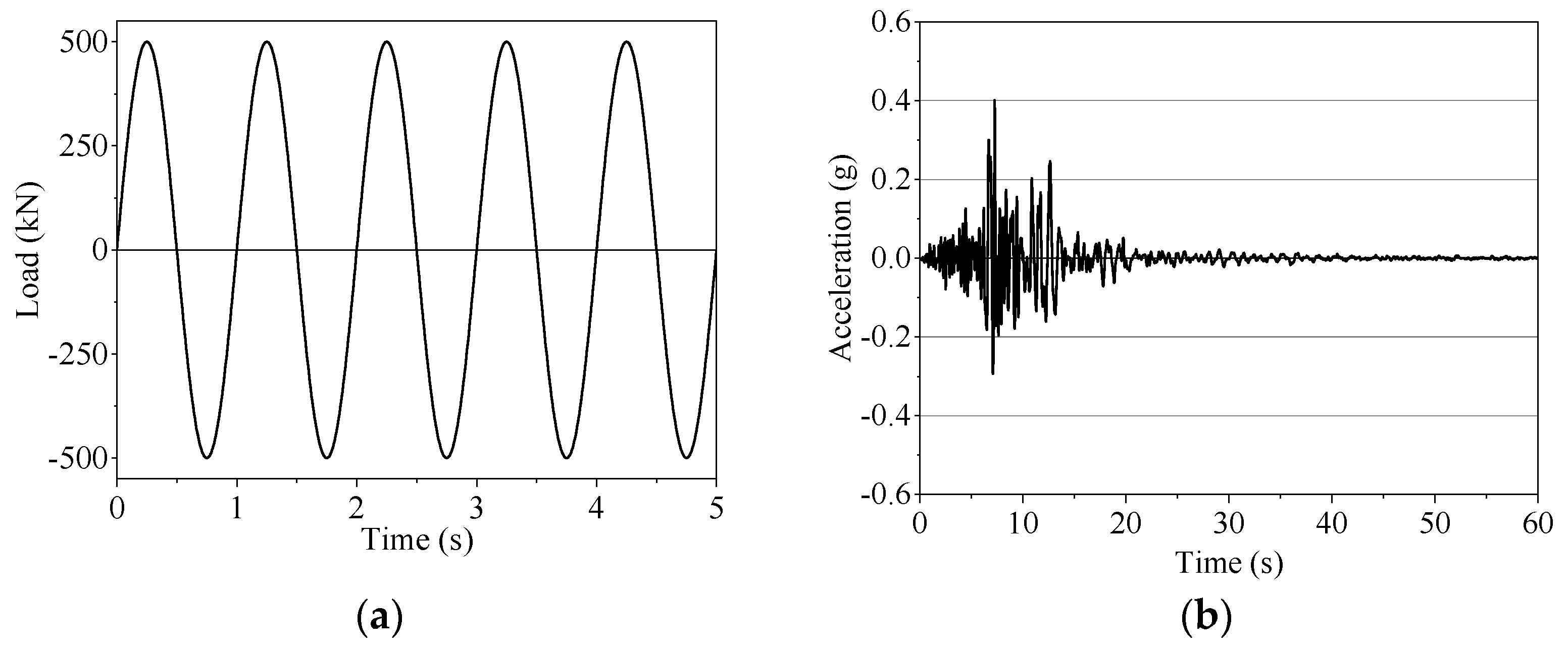
4.2. Dynamic Analysis

The incremental equation of a multi-degree-of-freedom system subjected to the earthquake is as follows:
[ M ] { Δ u ¨ } + [ C ] { Δ u ˙ } + [ K ] { Δ u } = { Δ F }
where the vectors of incremental acceleration, velocity, and displacement are { Δ u ¨ } , { Δ u ˙ } , and { Δ u } , respectively; the stiffness, mass, and damping matrices are [ K ] , [ M ] , and [ C ] , respectively; the external load increment vector is Δ F = M Δ a , in which a is the earthquake ground acceleration.
The damping matrix [ C ] can be defined as [40]:
[ C ] = α [ M ] + β [ K ]
where α and β are mass and stiffness proportional damping factors, respectively. With the adoption of the average acceleration method of the Newmark: γ = 1 / 2 ; β = 1 / 4 [40]. To solve Equation (19), the study uses the Newmark method to analyze segments linearly with a very small time step. The main steps are as follows:
1. Initial calculations:
Step 1.1: Choose Δt;
Step 1.2: { u ¨ 0 } = { F 0 } [ C ] { u ˙ 0 } [ K ] { u 0 } [ M ]
2. Calculations for each time step, i = 0, 1, 2…
Step 2.1: [ K ^ ] = [ K ] + γ β Δ t [ C ] + 1 β ( Δ t ) 2 [ M ]
Step 2.2: a = 1 β Δ t [ M ] + γ β [ C ] and b = 1 2 β [ M ] + Δ t ( γ 2 β 1 ) [ C ]
Step 2.3: { Δ F } = { Δ F } + a { u ˙ i } + b { u ¨ i }
Step 2.4: { Δ u i } = { Δ F } [ K ^ ]
Step 2.5: { Δ u ˙ i } = γ β Δ t { Δ u i } γ β { u ˙ i } + Δ t ( 1 γ 2 β ) { u ¨ i }
Step 2.6: { Δ u ¨ i } = 1 β ( Δ t ) 2 { Δ u i } 1 β Δ t { u ˙ i } 1 2 β { u ¨ i }
Step 2.7: { u i + 1 } = { u i } + { Δ u i } ; { u ˙ i + 1 } = { u ˙ i } + { Δ u ˙ i } ; { u ¨ i + 1 } = { u ¨ i } + { Δ u ¨ i }
Step 2.8: Find internal forces from ui+1: M, N, Q;
Step 2.9: Check the model: compare shear force Q with Qy—updated values of k for the next step.
3. Repetition for the next time step: replace i with i + 1 and implement steps 2.1 to 2.9 for the next step.
To integrate the system of Equation (19), at the time ti+1, in addition to having to find the values of { u } = { u i + 1 } , { u ˙ } = { u ˙ i + 1 } , and { u ¨ } = { u ¨ i + 1 } , we also have to find the values of the shear force of the beam with the energy dissipation device because the Equation (19) is subjected to binding by the selected association model as presented in Figure 11.
When analyzing Equation (19), for each time step, the shear force calculated must be compared with that of the previous time step. If the increase-decrease process of the shear force just calculated is the same as the increase-decrease process in the previous time step, then the relationship is appropriate and used to calculate the next time step. If there is any difference from the previous increase-decrease rule, that time step is considered to contain a change in hardness. And, at that time, it is necessary to check the increment of the shear force. That could be accepted if being small enough otherwise it must be recalculated for that time step.

5. Comparison to Commercial Software

Popular commercial Structural software such as SAP2000 v22, ANSYS 2023, and ABAQUS 2023 model the coupling beam with an energy dissipation device by subdividing it into two rigid segments, one beam element and one zero-length element as a device [23,30]. However, in this study, a program proposed for the Analysis of the Frame with Damper (AFD), based on the Matlab programming language [41], applied with the Newmark method of numerical integration, models the coupling beam as one element (EDCB element). In light of this, the number of elements for structural modeling can be significantly reduced. In this section, a 1-story frame and a 10-story coupled shear wall structure with coupling beams fitted with energy dissipation devices using a stiffness matrix as proposed and AFD programming for analysis, then comparing the results using SAP2000 software [36] to evaluate the accuracy of the developed program.

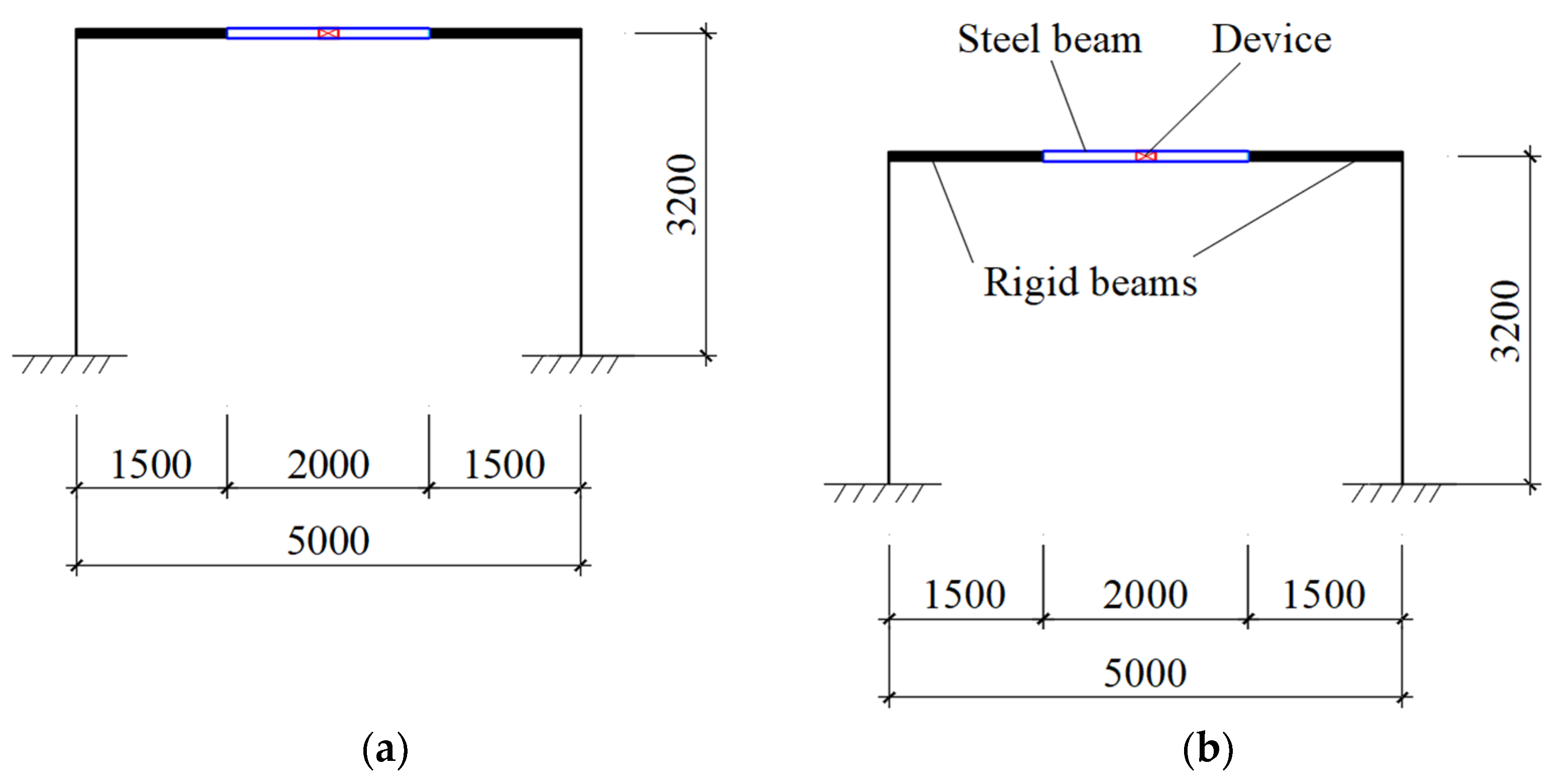
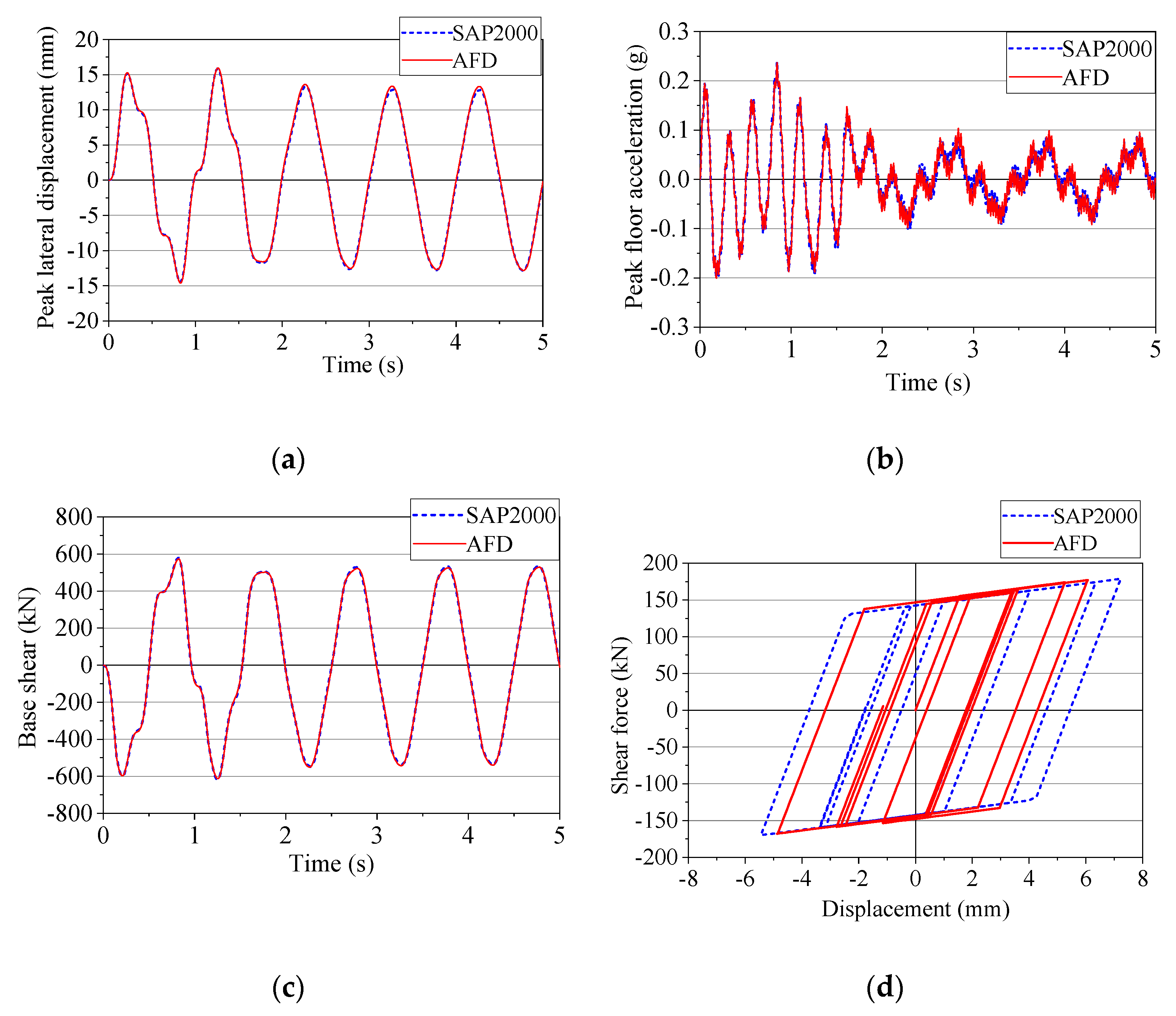
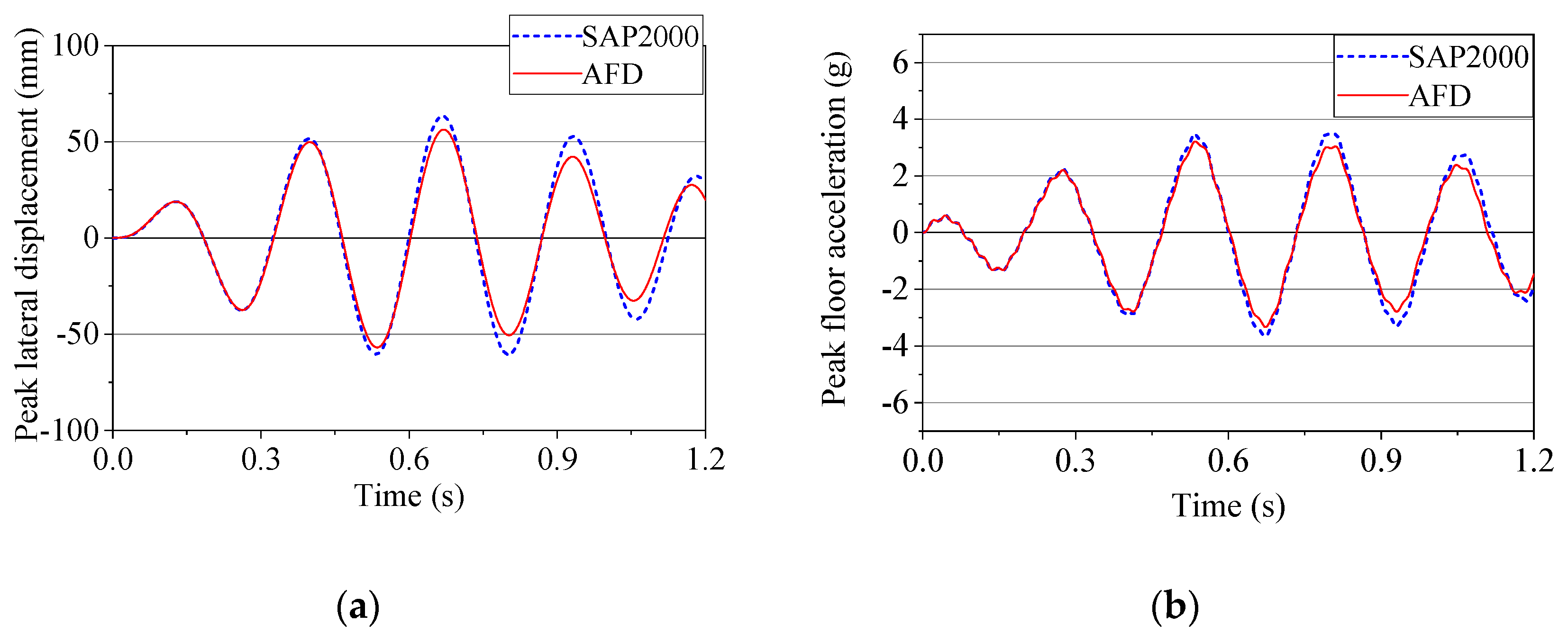
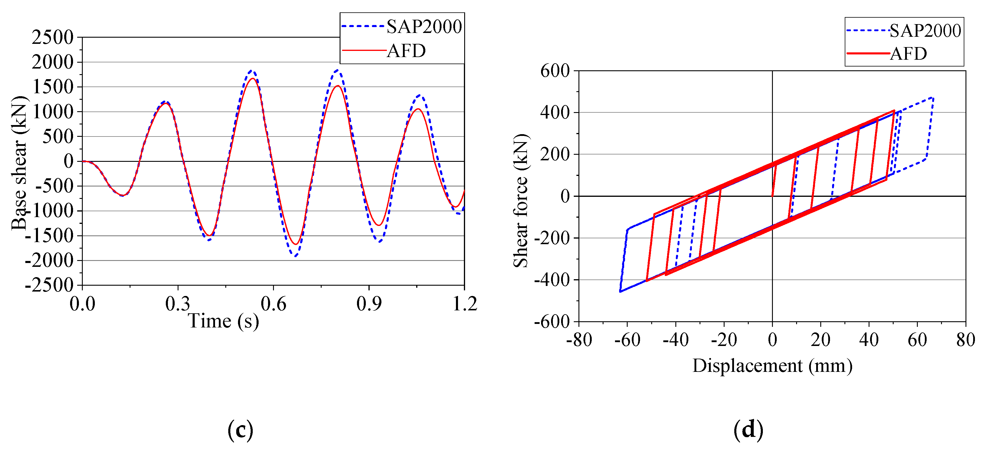
5.1. One-Story Frame

The first example is a one-story frame with the geometry presented in Figure 12a. The columns have a cross-section of 300 × 500 ( mm ) using reinforced concrete materials with the elastic modulus E b = 23,000 ( MPa ) and the Poisson’s ratio μ = 0.2. The entire beam including two rigid beams, one steel beam, and an energy dissipation device located in its middle is modeled as the EDCB element. The parameters of the steel beam and device are the steel beam’s material parameters: elastic modulus E b = 210,000 ( MPa ) ; Poisson’s ratio μ = 0.3; beam cross-section: depth 400 (mm), flange width 250 (mm), flange thickness 12 (mm), and web thickness 10 (mm); and the device’s parameters Q y = 150 ( kN ) , k 1 = 100,000 ( kN / m ) , k 2 = 5000 ( kN / m ) [42] (Figure 11). Dead and live loads imposed on the floor are, respectively, 9.7 (kN/m2) and 2.0 (kN/m2). The beam in SAP2000 software is composed of 4 elements: 2 absolutely rigid beam elements, 1 steel beam element, and 1 device model element (MultiLinear Plastic link element) (Figure 12b) [43,44].
A frame survey is conducted under the case of harmonic load P(t) placed at the top of the building with a sine wave having the largest amplitude of 500 (kN) in two case: (1) the harmonic load P(t) with the period of sine wave of 1.0 (s) (Figure 13a) and (2) the period of sine wave of 0.2485 (s), which is the same with the fundamental vibration period of the 1st mode of the 1-story frame. Figure 14 and Figure 15 show the results of peak lateral displacement, peak floor acceleration, base shear, the shear force-displacement relationship of the device under harmonic load, comparison between the AFD program and SAP2000 software in two cases. Based on the outcomes, it can be seen that the results achieved using AFD agree well with those of SAP2000.

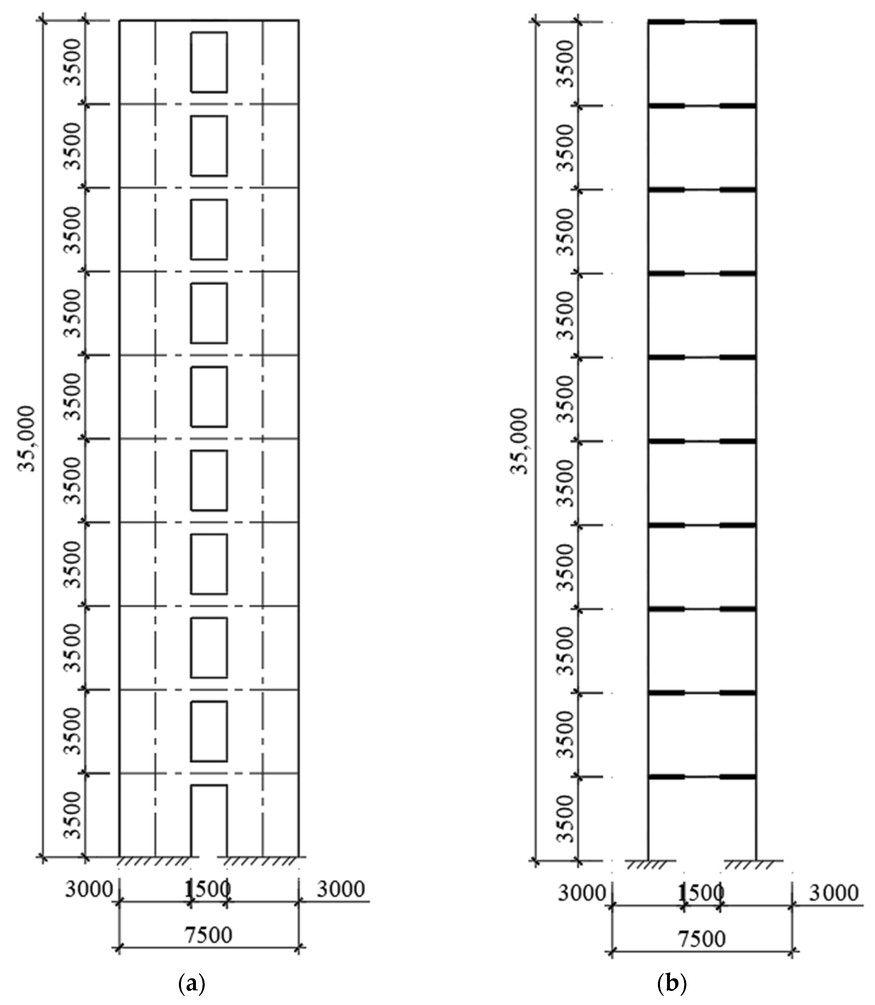
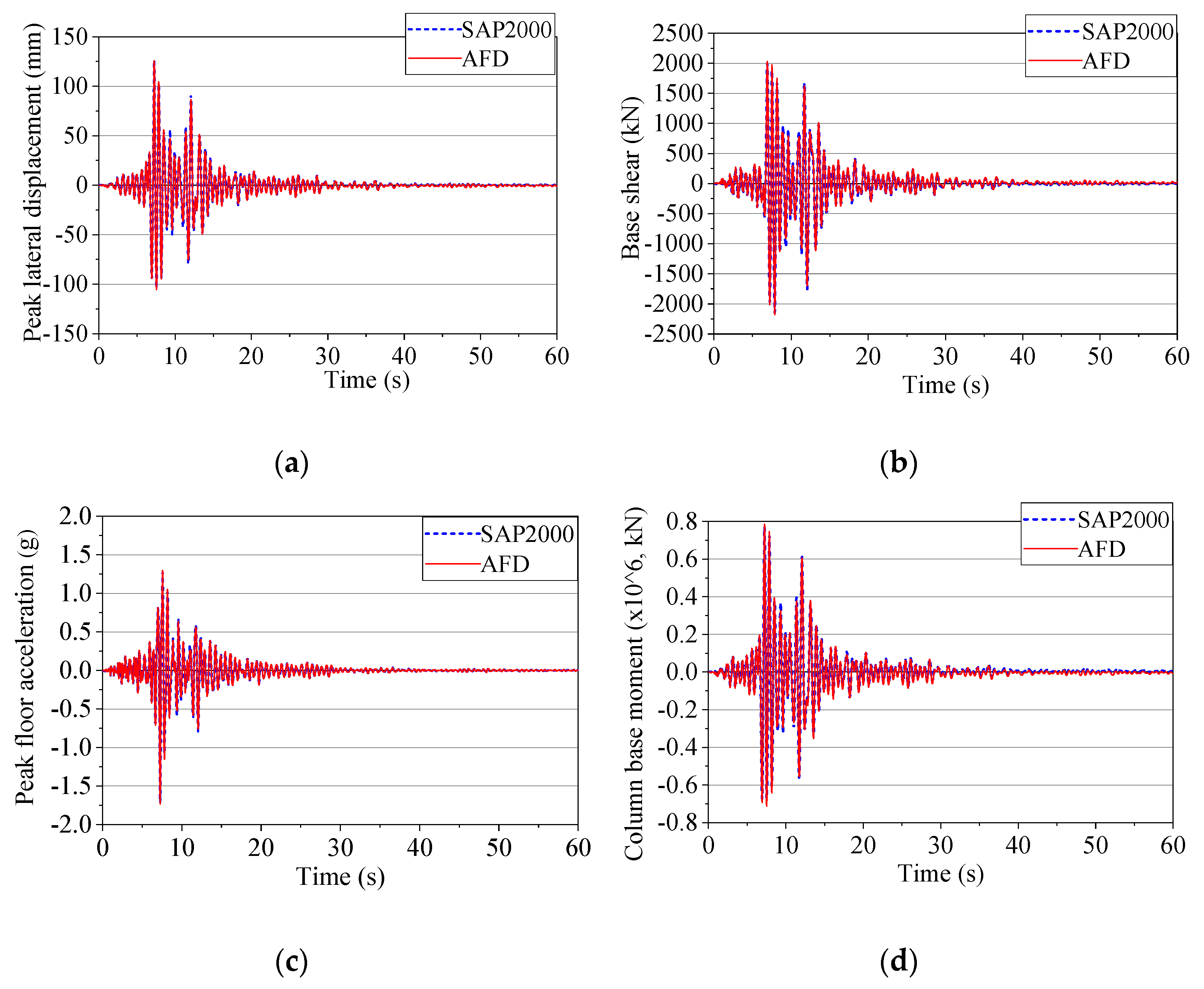
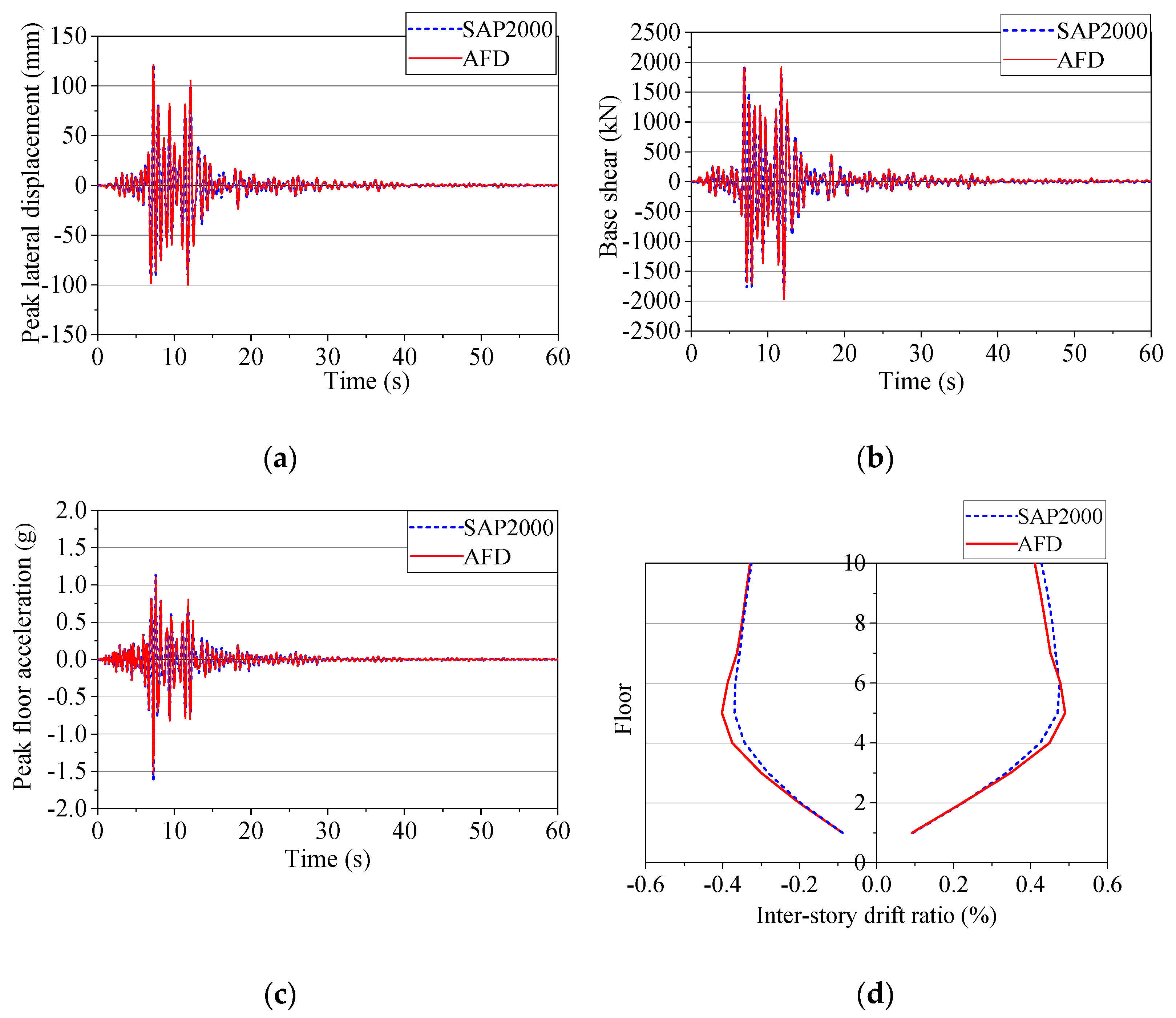
5.2. Ten-Story Coupled Shear Wall
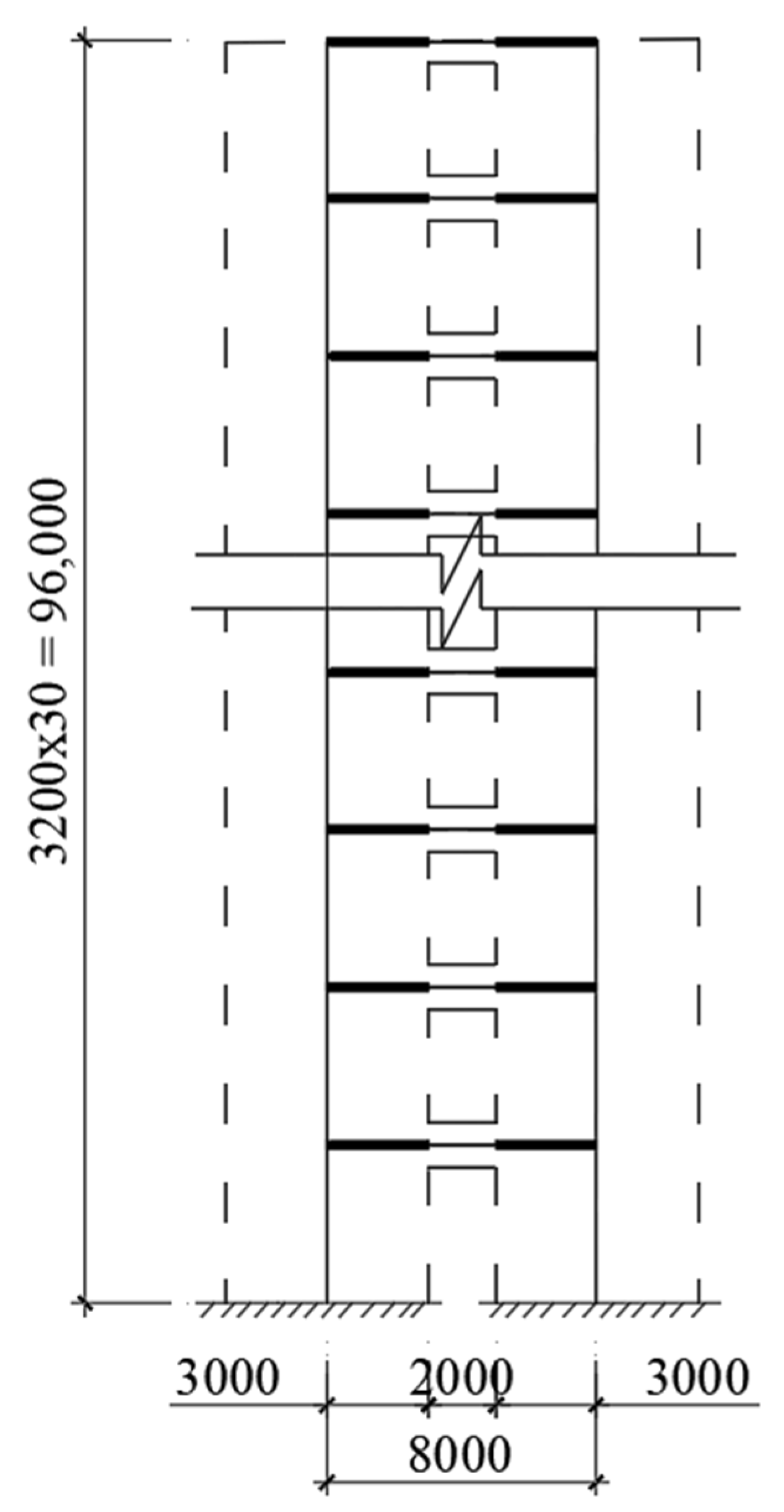
The coupled shear wall structure is situated in Site Class C soils and consists of 10 stories which have 3.5 (m) height for each story and 35 (m) for the total structure (Figure 16). Columns using reinforced concrete materials have a cross-section of 3000 × 250 ( mm ) with elastic modulus E b = 25,000 ( MPa ) and Poisson’s ratio μ = 0.2. A steel beam has material parameters: elastic modulus E b = 210,000 ( MPa ) ; Poisson’s ratio μ = 0.3; beam cross-section: depth of 1000 (mm), flange width of 250 (mm), flange thickness of 12 (mm), and web thickness of 12 (mm). The beam has 2 absolutely rigid segments at its two ends and an energy dissipation device located at its middle with device parameters Q y = 420 ( kN ) , k 1 = 560,000 ( kN ) , and k 2 = 56,000 ( kN ) [45] (Figure 11). The lumped mass at each node is assumed to be 20,380 (kg). The CAST360 record in design basis earthquake level (DBE) of the Northridge earthquake as shown in Figure 13b is used as ground excitation [46].
To verify the accuracy and efficiency of the proposed program in analyzing the nonlinear response of coupled shear wall with energy dissipation device under earthquake loading. There are two cases of placing energy dissipation devices at different locations device located on the 1st floor and the device added from the 3rd to 5th floor, to be investigated. The peak lateral displacement, base shear, peak floor acceleration, and base moment of the building of the first case, respectively, generated by the AFD program and SAP2000 are shown in Figure 17. Moreover, Figure 18 illustrates peak lateral displacement, base shear, peak floor acceleration, and inter-story drift ratio of coupled shear wall with the device at floors 3 to 5. It can be observed that the responses of the structure under earthquake obtained by the proposed program AFD and SAP2000 are nearly the same.

6. Case Study

To evaluate the effectiveness of using an energy dissipation device in coupled shear wall structures, this section will carry out an analysis of a 30-story coupled shear wall structure with an energy dissipation device in a coupling beam under earthquake loading as presented in Figure 19. In this case study, the proposed EDCB element and program AFD are used. The parameters of the energy dissipation device and earthquake record are the same as the 10-story analysis. The height of the 30-story building is 96 (m) with a story height of 3.2 (m). Concrete with elastic modulus E b = 34,500 ( MPa ) is used for reinforced concrete shear walls. The thickness of the studied reinforced concrete shear walls varied along with stories: 700 (mm) for 1st and 2nd stories, 600 (mm) for 3rd to 8th stories, 500 (mm) for 9th to 12th stories, 400 (mm) for 13th to 16th stories, and 300 (mm) for remaining stories. A steel beam has material parameters: elastic modulus E b = 210,000 ( MPa ) ; Poisson’s ratio μ = 0.3; cross-section of I-beam without energy dissipation device: depth of 700 (mm), flange width of 250 (mm), flange thickness of 12 (mm), and web thickness of 10 (mm). Steel box beam is used for beam has energy dissipation device with a depth of 700 (mm), a width of 250 (mm), and a thickness of 8 (mm). The study surveyed three cases: 1 device, 10 devices, and 30 devices added in coupled shear walls. With the same data of energy dissipation device as above, the purpose of the survey is to find out the effective device placement for the building under the impact of earthquakes.

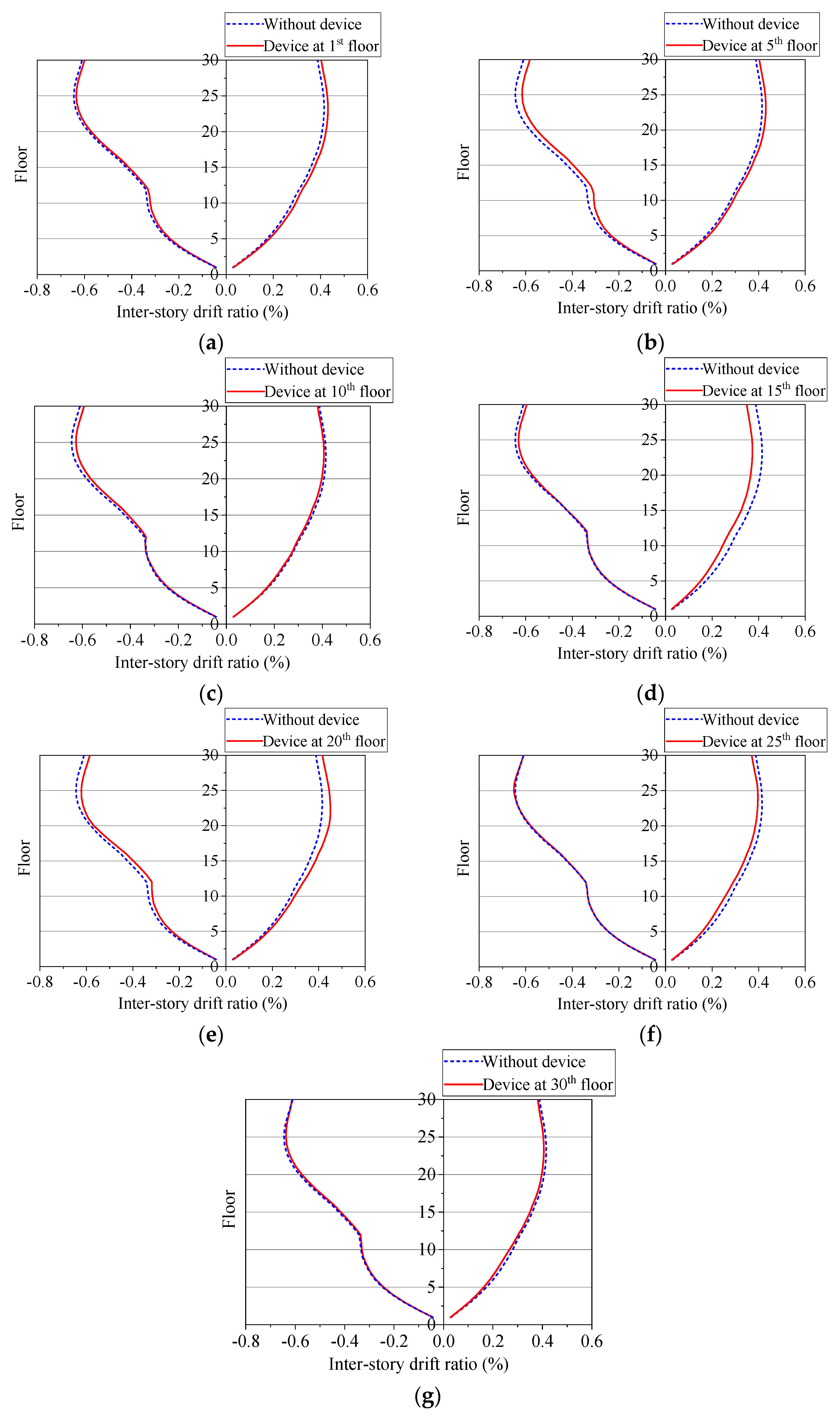
6.1. One Device Assign in Coupled Shear Wall Structure

Under the earthquake record CAST360_DBE, the structure behavior when added one an energy dissipation device to a coupled shear wall is considered. Seven cases are conducted corresponding to the energy dissipation device on the floor: 1, 5, 10, 15, 20, 25, and 30. The results of the inter-story drift ratio of the building in the case of with and without energy dissipation devices are shown in Figure 20.
The inter-story drift ratio is an important index, which can reflect the damage to the structural components. Based on the results from Figure 20, it can be seen that when the building has only one energy dissipation device, the inter-story drift ratio does not change much compared with when the coupled shear wall is without the device, except for the case when the device is used at 15th floor. Figure 20d shows the maximum inter-story drift is reduced by 11.3 (%) from 0.415 (%) to 0.373 (%) corresponding to the case without and with the device added on the 15th floor.

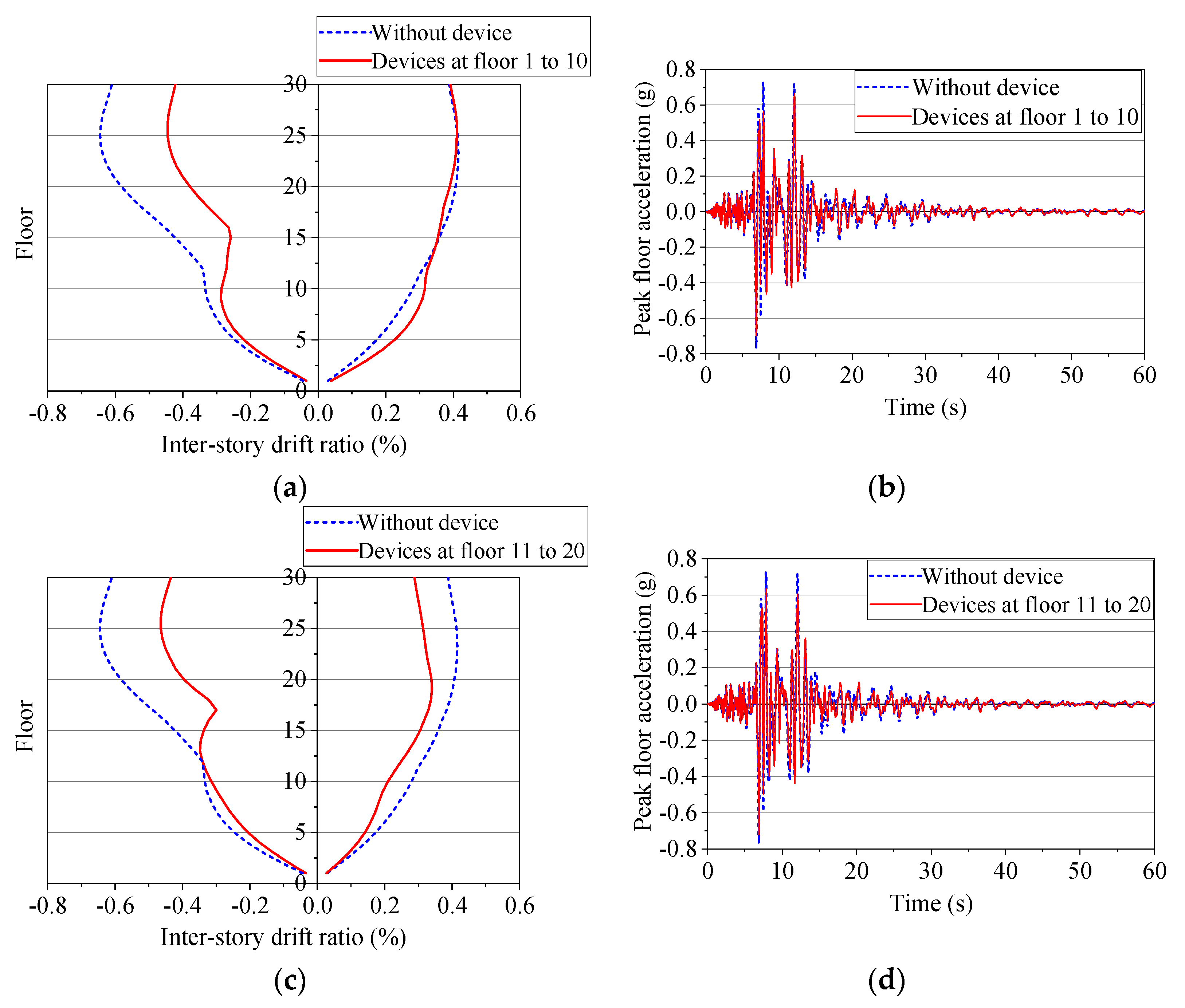
6.2. Ten Devices Assigned in Coupled Shear Wall Structure

This case study was carried out to evaluate the behavior of a 30-story coupled shear wall structure when added by ten devices in different regions in the building such as devices at floors 1–10, 11–20, 21–30, 15–24, and 5–14 (Figure 21, Figure 22 and Figure 23). Compared with the structure without the device, the inter-story drift of a building with ten devices is reduced significantly. Table 1 below indicates the value of the level of reduction of inter-story drift when 10 devices were added to the structure compared to the system without the device, determined at the position with the largest difference.
The peak floor acceleration determined at the value of the 30th-floor acceleration is reduced when compared to the case when the device is not installed. At the time of 6.88 (s), the peak amplitude of the floor acceleration when the system is not equipped with an energy dissipation device is the largest −0.77 g, corresponding to that time the peak value of the floor acceleration in the survey cases: −0.70 g, −0.72 g, −0.64 g, −0.70 g, −0.69 g (for the cases of placing devices at floors 1–10, 11–20, 21–30, 5–14, 15–24, respectively).

6.3. Devices Assigned on Each Floor of the Coupled Shear Wall Structure

To analyze the 30-story coupled shear wall structure added energy dissipation device in all floors under the CAST360_DBE earthquake record, it can be seen that the significant effect shown by several important parameters including inter-story drift ratio, peak floor acceleration, and base shear compared to the building without the device (Figure 24). The inter-story drift ratio of the structure with 30 devices is reduced by 45 (%) to that without the device when comparing the maximum inter-story drift on the 23rd floor (0.415 (%) and 0.228 (%) without and with devices, respectively). Meanwhile, the peak floor acceleration when the building does not use an energy dissipation device has the largest amplitude at 6.88 (s) at −0.77 g, corresponding to −0.57 g when 30 devices are assigned to the building (a decrease of 26 (%)).
The value of the base shear of the system without any device and with devices added in at all floors varies greatly in both their value and direction, in which the greatest absolute value of base shear without any device and with 30 devices added are 10,503 (kN) and 7306 (kN), respectively.

6.4. Discussions

Based on the results, it can be seen that when there is only one energy dissipation device, the behavior of the building does not change much compared to when it does not use the device, except for the case where one device is installed on the 15th floor. Otherwise, in the case of using 10 devices in the building, the inter-story drift and the peak floor acceleration both decreased, with higher efficiency when placing equipment in the area from the 5th to the 14th floor. Hence, the location of the device that provides effective seismic resistance for a 30-story coupled shear wall structure is in the region from the 5th to the 15th floor. In addition, the inter-story drift, peak floor acceleration, and base shear are all significantly reduced when the energy dissipation device is installed on all floors, and show the efficiency of using the device on each floor of the building compared to other fields: one device or devices at a certain area. In terms of time for structural analysis, the 1-story frame consumed 2 (s) and 6 (s) when using the AFD program and SAP2000, respectively. With the 10-story coupled shear wall structure attached to the energy dissipation devices from the 3rd to 5th floor, the analysis time of the AFD program is 22 (s), while SAP2000 uses 76 (s).
It is clear to see that the energy dissipation device which is placed not only on all floors but also on several floors gives the coupled shear wall structure a seismic effect. However, more research is needed to investigate the effective placement of the device in the specific case of the height of the structure or discontinuous installations. Moreover, the paper only studies the energy dissipation device belonging to the metallic damper not yet evaluating the effectiveness of other types of damper such as viscous damper and friction damper. Further studies are needed to carry out to compare the seismic effect to the coupled shear wall structure when using different types of energy dissipation devices in the same area.

7. Conclusions

For the nonlinear inelastic analysis of coupled shear wall structure with the energy dissipation device in coupling beams, the EDCB element and AFD program are proposed. The following major conclusions are postulated, which are based on the results presented above:
(1)
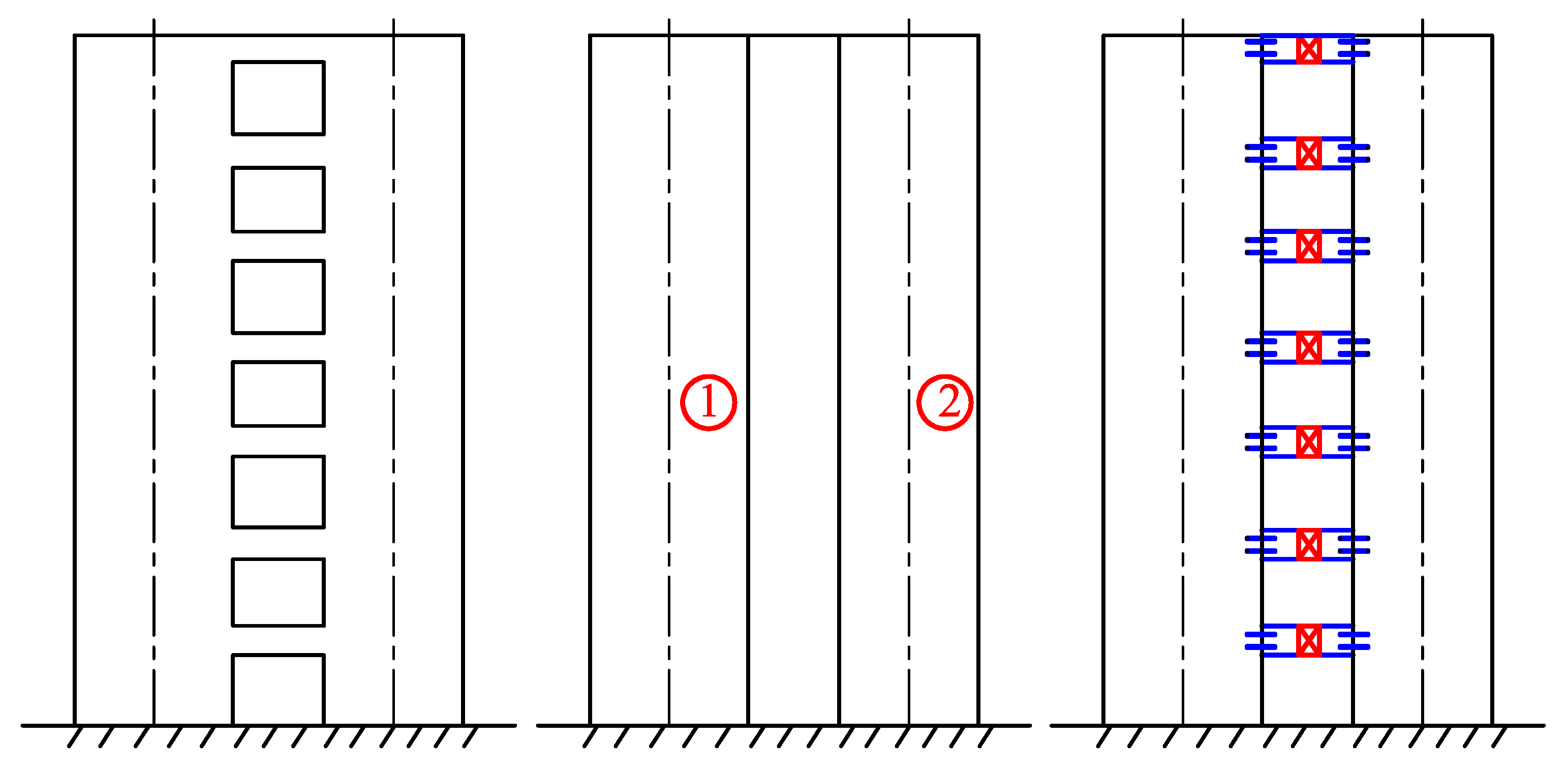
The coupling beam assigned with the energy dissipation device in coupled shear wall structure can be modeled as 1 element (EDCB element), using the proposed stiffness matrix.
(2)
The AFD program demonstrates the accuracy and computational efficiency in analyzing the hysteretic behavior of coupling beams as well as static and dynamic analysis of structures.
(3)
The good results obtained from the analyses of the 1-story frame and 10-story coupled shear wall showed that the proposed software proves to be reliable and valuable for application.
(4)
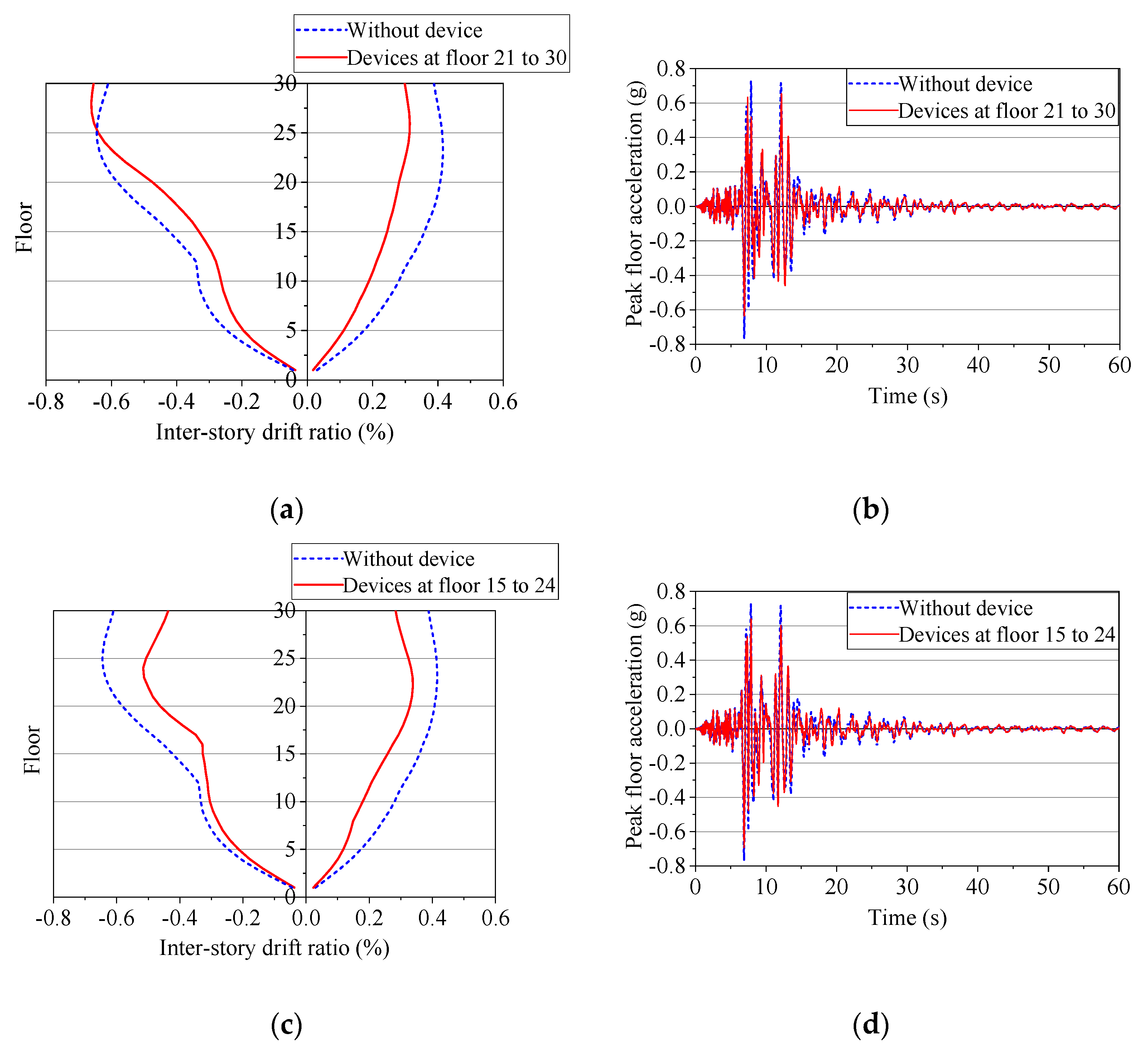
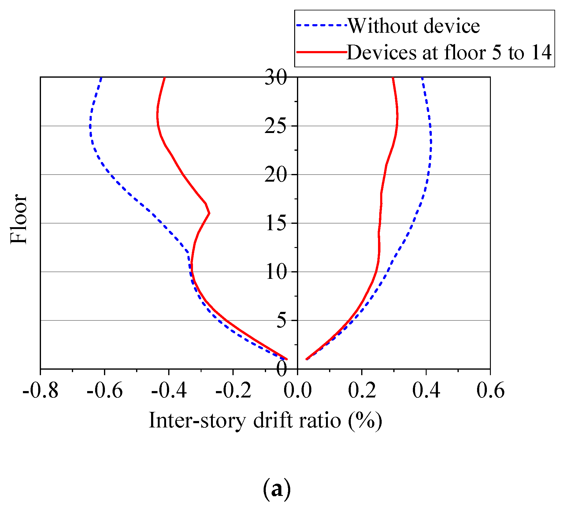
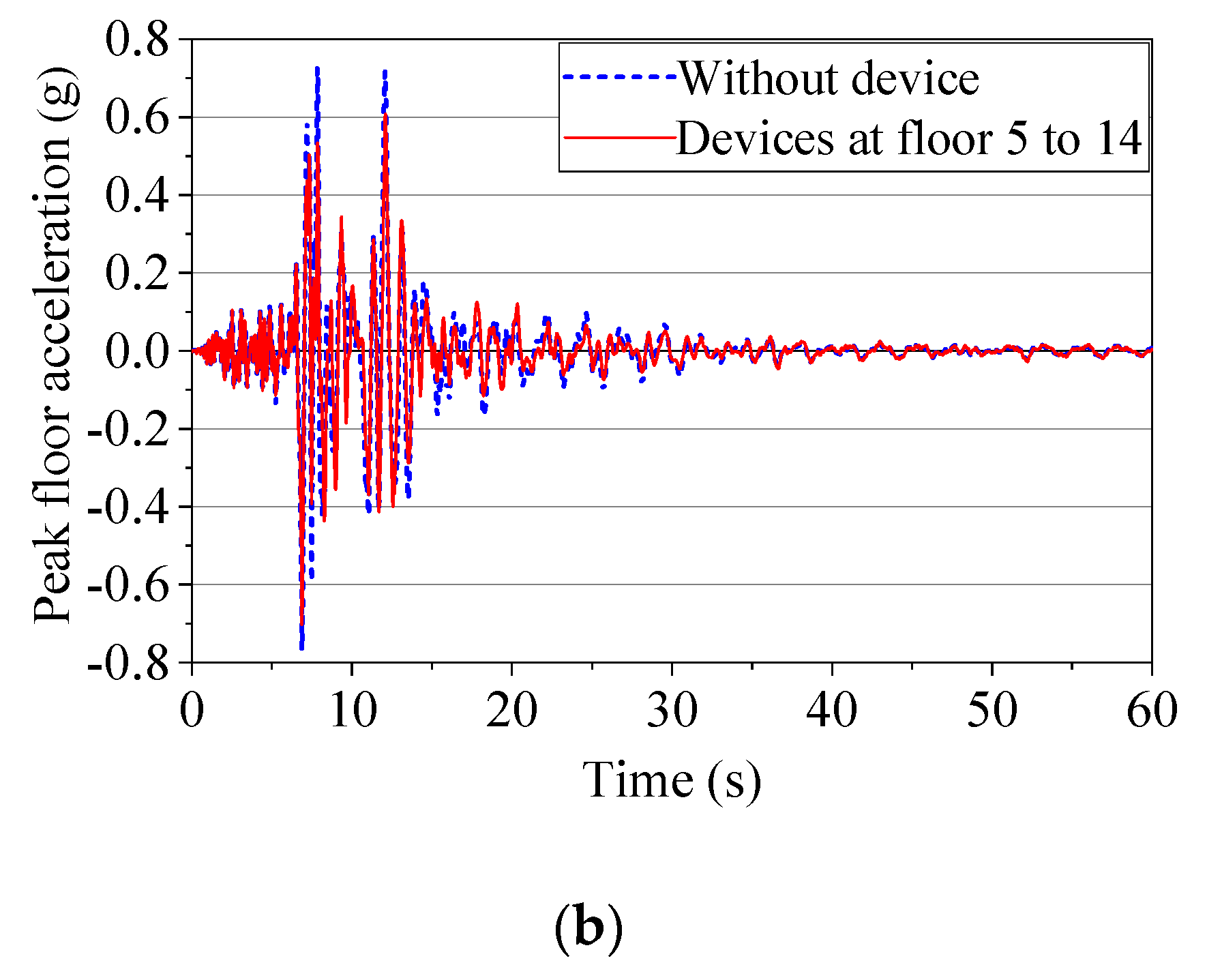
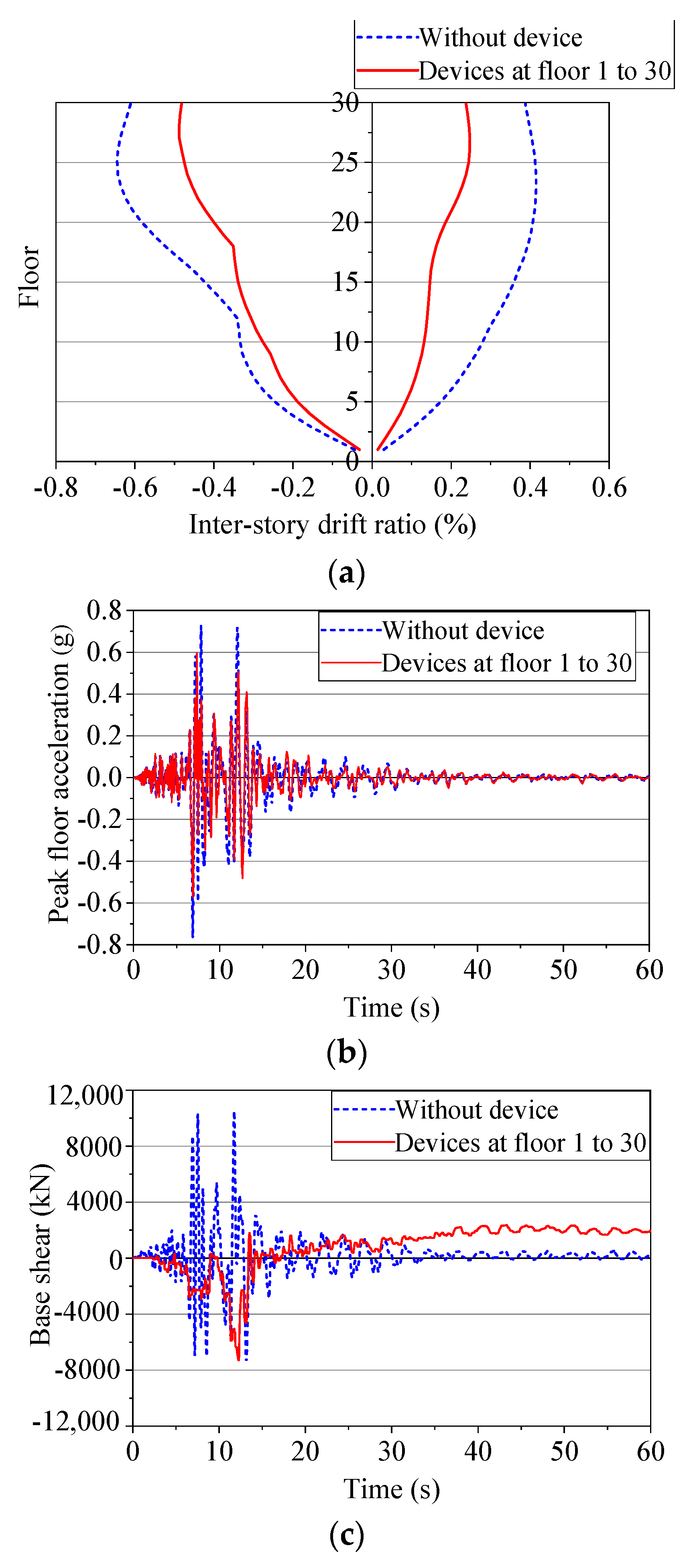
By adopting the EDCB element and AFD program, considering the 30-story coupled shear wall in seismic analysis, the use of an energy dissipation device could bring an obvious effect to decrease the probability of damage to the structure, especially when the energy dissipation device is located in the region from the 5th floor to the 15th floor and all floors.
(5)
Using the AFD program could help to cut down significantly survey time due to the decrease in the number of elements, especially when many energy dissipation devices are assigned to the building.
The readers are free to contact via email the corresponding author if have any more clarification regarding the article or proposed program.

Author Contributions

Conceptualization, T.-H.P. and A.-D.N.; methodology, H.-Q.N. and T.-C.N.; software, T.-H.P. and A.-D.N.; validation, T.-H.P., H.-Q.N. and T.-C.N.; formal analysis, T.-H.P. and A.-D.N.; investigation, T.-C.N.; resources, T.-H.P.; data curation, T.-H.P., H.-Q.N. and T.-C.N.; writing—original draft preparation, T.-H.P.; writing—review and editing, A.-D.N.; visualization, T.-H.P.; supervision, T.-C.N. and A.-D.N.; project administration, A.-D.N.; funding acquisition, A.-D.N. All authors have read and agreed to the published version of the manuscript.

Funding

This research received no external funding.

Data Availability Statement

No new data were created.

Conflicts of Interest

The authors declare no conflict of interest.

References

  1. Cao, X.-Y.; Shen, D.; Feng, D.-C.; Wang, C.-L.; Qu, Z.; Wu, G. Seismic Retrofitting of Existing Frame Buildings through Externally Attached Sub-Structures: State of the Art Review and Future Perspectives. J. Build. Eng. 2022, 57, 104904. [Google Scholar] [CrossRef]
  2. Park, P.; Paulay, T. Reinforced Concrete Structures; Wiley-Interscience: Hoboken, NJ, USA, 1974. [Google Scholar]
  3. Pham, D.; Chou, C. Strong-Axis Instability of Sandwiched Buckling Restrained Braces in a Two-Story Steel X-BRBF: Seismic Tests and Finite Element Analyses. Thin Walled Struct. 2020, 157, 107011. [Google Scholar] [CrossRef]
  4. Soong, T.T.; Spencer, B.F. Supplemental Energy Dissipation: State-of-the-Art and State-of-the-Practice. Eng. Struct. 2002, 24, 243–259. [Google Scholar] [CrossRef]
  5. Spencer, B.F.; Nagarajaiah, S. State of the Art of Structural Control. J. Struct. Eng. 2003, 129, 845–856. [Google Scholar] [CrossRef]
  6. Aiken, I.D.; Kelly, J.M.; Hall, A.S. Seismic Response of a Nine-Story Steel Frame with Friction-Damped Cross-Bracing; Report No. UCB/EERC-88/17; Pacific Earthquake Engineering Research Center, University of California: Berkeley, CA, USA, 1988; pp. 1–7. [Google Scholar]
  7. Symans, M.D.; Charney, F.A.; Whittaker, A.S.; Constantinou, M.C.; Kircher, C.A.; Johnson, M.W.; McNamara, R.J. Energy Dissipation Systems for Seismic Applications: Current Practice and Recent Developments. J. Struct. Eng. 2008, 134, 3–21. [Google Scholar] [CrossRef] [Green Version]
  8. Stafford-Smith, B.; Coull, A. Tall Building Structure—Analysis and Design, 1st ed.; Wiley-Interscience: Hoboken, NJ, USA, 1991. [Google Scholar]
  9. Shiva Prathap, H.K.; Somesh, P.; DeviPrasad; Bharath, V.B. Comparative Study of Multi-Storey Building with Coupled Shear Wall and Multi-Storey Building with Conventional Shear Wall. Int. Res. J. Eng. Technol. 2019, 6, 190–195. [Google Scholar]
  10. Cao, X.-Y.; Feng, D.-C.; Li, Y. Assessment of Various Seismic Fragility Analysis Approaches for Structures Excited by Non-Stationary Stochastic Ground Motions. Mech. Syst. Signal Process 2023, 186, 109838. [Google Scholar] [CrossRef]
  11. Cao, X.-Y.; Feng, D.-C.; Beer, M. Consistent Seismic Hazard and Fragility Analysis Considering Combined Capacity-Demand Uncertainties via Probability Density Evolution Method. Struct. Saf. 2023, 103, 102330. [Google Scholar] [CrossRef]
  12. Hosseini, R.; Rashidi, M.; Bulajić, B.Đ.; Arani, K.K. Multi-Objective Optimization of Three Different SMA-LRBs for Seismic Protection of a Benchmark Highway Bridge against Real and Synthetic Ground Motions. Appl. Sci. 2020, 10, 4076. [Google Scholar] [CrossRef]
  13. Choi, K.-S.; Kim, H.-J. Strength Demand of Hysteretic Energy Dissipating Devices Alternative to Coupling Beams in High-Rise Buildings. Int. J. High Rise Build. 2014, 3, 107–120. [Google Scholar]
  14. Ahn, T.-S.; Kim, Y.-J.; Kim, S.-D. Large-Scale Testing of Coupled Shear Wall Structures with Damping Devices. Adv. Struct. Eng. 2013, 16, 1943–1955. [Google Scholar] [CrossRef]
  15. Hu, X.; Lu, Q.; Xu, Z.; Zhang, S. Seismic Performance of Reinforced Concrete Coupled Walls with Segmental Coupling Beams. Adv. Civ. Eng. 2019, 2019, 1520375. [Google Scholar] [CrossRef]
  16. Paulay, T. The Coupling of Shear Walls; University of Canterbury: Christchurch, New Zealand, 1969. [Google Scholar]
  17. Paulay, T.; Binney, J.R. Diagonally Reinforced Coupling Beams of Shear Walls. Symp. Pap. 1974, 42, 579–598. [Google Scholar]
  18. Tassios, T.; Moretti, M.; Bezas, A. On the Behavior and Ductility of Reinforced Concrete Coupling Beams of Shear Walls. Struct. J. 1996, 93, 711–720. [Google Scholar]
  19. Galano, L.; Vignoli, A. Seismic Behavior of Short Coupling Beams with Different Reinforcement Layouts. Struct. J. 2000, 97, 876–885. [Google Scholar] [CrossRef] [Green Version]
  20. Harries, K.A.; Mitchell, D.; Cook, W.D.; Redwood, R.G. Seismic Response of Steel Beams Coupling Concrete Walls. J. Struct. Eng. 1993, 119, 3611–3629. [Google Scholar] [CrossRef] [Green Version]
  21. Gong, B.; Shahrooz, B.M. Steel—Concrete Composite Coupling Beams—Behavior and Design. Eng. Struct. 2001, 23, 1480–1490. [Google Scholar] [CrossRef]
  22. Fortney, P.J.; Shahrooz, B.M.; Rassati, G.A. Large—Scale Testing of a Replaceable “Fuse” Steel Coupling Beam. J. Struct. Eng. 2007, 133, 1801–1807. [Google Scholar] [CrossRef]
  23. Pan, C.; Weng, D.G. Study on Seismic Performance of Coupled Shear Walls with Vertical Dampers. Adv. Mater. Res. 2010, 163–167, 4185–4193. [Google Scholar] [CrossRef]
  24. Montgomery, M.; Christopoulos, C. Experimental Validation of Viscoelastic Coupling Dampers for Enhanced Dynamic Performance of High-Rise Buildings. J. Struct. Eng. 2015, 141, 04014145. [Google Scholar] [CrossRef]
  25. Li, Y.; Xu, J.; Ma, K.; Yu, H. Seismic Behavior of Coupled Wall Structure with Steel and Viscous Damping Composite Coupling Beams. J. Build. Eng. 2022, 52, 104510. [Google Scholar] [CrossRef]
  26. Esteghamati, M.Z.; Farzampour, A. Probabilistic Seismic Performance and Loss Evaluation of a Multi-Story Steel Building Equipped with Butterfly-Shaped Fuses. J. Constr. Steel Res. 2020, 172, 106187. [Google Scholar] [CrossRef]
  27. Jiang, H.; Li, S.; He, L. Experimental Study on a New Damper Using Combinations of Viscoelastic Material and Low-Yield-Point Steel Plates. Front Mater. 2019, 6, 100. [Google Scholar] [CrossRef]
  28. Oh, S.H.; Choi, K.Y.; Kim, H.-J.; Kang, C.H. Experimental Validation on Dynamic Response of RC Shear Wall Systems Coupled with Hybrid Energy Dissipative Devices. In Proceedings of the 15 WCEE LISBOA, Lisbon, Portugal, 24–28 September 2012. [Google Scholar]
  29. Zhao, Y.; Dong, Y. Seismic Response of Reinforced Concrete Frame-Shear Wall Structure with Metal Rubber-Based Damper in Coupling Beam. ACSM 2020, 44, 319–326. [Google Scholar] [CrossRef]
  30. Beyer, K.; Dazio, A.; Priestley, M.J.N. Inelastic Wide-Column Models for U-Shaped Reinforced Concrete Walls. J. Earthq. Eng. 2008, 12, 1–33. [Google Scholar] [CrossRef]
  31. Soong, T.T.; Dargush, G.F. Passive Energy Dissipation Systems in Structural Engineering; John Wiley and Sons: Hoboken, NJ, USA, 1997. [Google Scholar]
  32. Prager, W. A New Method of Analyzing Stresses and Strains in Work-Hardening Plastic Solids. J. Appl. Mech. 1956, 23, 493–496. [Google Scholar] [CrossRef]
  33. Nakashima, M.; Akazawa, T.; Tsuji, B. Strain-Hardening Behavior of Shear Panels Made of Low-Yield Steel. II: Model. J. Struct. Eng. 1995, 121, 1750–1757. [Google Scholar] [CrossRef]
  34. Akazawa, T.; Nakashima, M.; Sakaguchi, O. Simple Model for Simulating Hysteretic Behavior Involving Significant Strain Hardening. In Proceedings of the Eleventh World Conference on Earthquake Engineering, Paper, Acapulco, Mexico, 23–28 June 1996. [Google Scholar]
  35. Mander, J.B.; Priestley, M.J.N.; Park, R. Theoretical Stress–Strain Model for Confined Concrete. J. Struct. Eng. 1988, 114, 1804–1826. [Google Scholar] [CrossRef] [Green Version]
  36. CSI. SAP2000 Integrated Solution for Structural Analysis and Design. 2019. Available online: http://www.csiamerica.com/ (accessed on 15 October 2022).
  37. William, B.B. Mechanics of Solids: Concepts and Applications; Irwin: Toronto, ON, Ontario, 1993. [Google Scholar]
  38. Öchsner, A. Classical Beam Theories of Structural Mechanics; Springer International Publishing: Cham, Switzerland, 2021. [Google Scholar] [CrossRef]
  39. Gaur, A.; Dhurvey, P. Comparative Study of Beam Theories on the Effect of Span-Depth Ratio for Symmetric and Un-Symmetric Loadings. IOP Conf. Ser. Mater. Sci. Eng. 2020, 936, 012047. [Google Scholar] [CrossRef]
  40. Chopra, A.K. Dynamics of Structures: Theory and Applications to Earthquake Engineering, 4th ed.; Prentice Hall: Upper Saddle River, NJ, USA, 2012. [Google Scholar]
  41. The Math Works, Inc. MATLAB. 2017. Available online: https://www.mathworks.com/ (accessed on 15 October 2022).
  42. Huang, X. Seismic Mitigation Efficiency Study of the Coupling Beam Damper in the Shear Wall Structure. Civ. Eng. J. 2021, 30. [Google Scholar] [CrossRef]
  43. Thu-Hien, P. Seismic Analyses of Self-Centering Braced Frames and Buckling-Restrained Braced Frames Using the Computer Program SAP2000. Master’s Thesis, Department of Civil Engineering, National Taiwan University, Taipei, Taiwan, 2012. [Google Scholar]
  44. Wen, W.; Luo, M.; Chen, L.; Ma, Z.; Pan, W. An Equivalent Approach for Modelling Butterfly-Hysteresis Passive Variable Friction Damper. SN Appl. Sci. 2022, 4, 234. [Google Scholar] [CrossRef]
  45. Wang, T.; Guo, X.; He, X.; Du, Y.; Duan, C. Seismic Behavior of High-Rise Concrete Shear-Wall Buildings with Hybrid Coupling Beams. In Proceedings of the 15 WCEE LISBOA, Lisbon, Portugal, 24–28 September 2012. [Google Scholar]
  46. Earthquake Engineering Research Center. Preliminary Report on the Seismological and Engineering Aspects of the January 17, 1994 Northridge Earthquake; UCB/EERC-94/01; College of Engineering, University of California at Berkeley: Berkeley, CA, USA, 1994. [Google Scholar]
Figure 1. Material hardening laws: (a) Stress-strain curves; (b) Kinematic hardening.
Buildings 13 00941 g001aBuildings 13 00941 g001b
Figure 2. Stress-strain curve of material: (a) concrete; (b) steel.
Buildings 13 00941 g002
Figure 3. Structural model of the coupling beam with an energy dissipation device.
Buildings 13 00941 g003
Figure 4. Construction of a coupled shear wall with energy dissipation device.
Buildings 13 00941 g004
Figure 5. Structure of the beam with rigid ends.
Buildings 13 00941 g005
Figure 6. Beam member.
Buildings 13 00941 g006
Figure 7. Shear-deformation relationship.
Buildings 13 00941 g007
Figure 8. Elements of first column: (a) Unit translation at end i; (b) Internal force diagrams when unit translation at end i.
Buildings 13 00941 g008aBuildings 13 00941 g008b
Figure 9. Elements of second column: (a) Unit rotation at end i; (b) Internal force diagrams when unit rotation at end i.
Buildings 13 00941 g009
Figure 10. The beam with rigid zones at the ends.
Buildings 13 00941 g010
Figure 11. Shear-deformation relationship of the device.
Buildings 13 00941 g011
Figure 12. One-storey frame: (a) Details of frame; (b) Frame model using SAP2000.
Buildings 13 00941 g012
Figure 13. Loads: (a) Harmonic load P(t); (b) Earthquake record CAST360_DBE.
Buildings 13 00941 g013
Figure 14. Responses of the frame under harmonic load P(t) with the period of sine wave of 1.0 (s): (a) Peak lateral displacement; (b) Peak floor acceleration; (c) Base shear; (d) Hysteretic curve of energy dissipation device.
Buildings 13 00941 g014
Figure 15. Responses of the frame under harmonic load P(t) with the period of sine wave of 0.2485 (s): (a) Peak lateral displacement; (b) Peak floor acceleration; (c) Base shear; (d) Hysteretic curve of energy dissipation device.
Buildings 13 00941 g015aBuildings 13 00941 g015b
Figure 16. Ten–story coupled shear wall: (a) Coupled shear wall; (b) Frame analogy.
Buildings 13 00941 g016
Figure 17. Responses of building when a device added to the first floor: (a) Peak lateral displacement; (b) Base shear; (c) Peak floor acceleration; (d) Base moment.
Buildings 13 00941 g017
Figure 18. Responses of coupled shear wall structure: devices at floor 3 to 5: (a) Peak lateral displacement; (b) Base shear; (c) Peak floor acceleration; (d) Inter-story drift ratio.
Buildings 13 00941 g018
Figure 19. 30-story coupled shear wall.
Buildings 13 00941 g019
Figure 20. Inter-story drift ratio of structure when one device assigned at: (a) 1st floor; (b) 5th floor; (c) 10th floor; (d) 15th floor; (e) 20th floor; (f) 25th floor; (g) 30th floor.
Buildings 13 00941 g020
Figure 21. Behavior of structures: (a) Inter-story drift and (b) Floor acceleration on 30th floor: devices on floors 1 to 10; (c) Inter-story drift and (d) Floor acceleration on 30th floor: devices on floors 11 to 20.
Buildings 13 00941 g021
Figure 22. Behavior of structures: (a) Inter-story drift and (b) Floor acceleration on 30th floor: devices on floors 21 to 30; (c) Inter-story drift and (d) Floor acceleration on 30th floor: devices on floors 15 to 24.
Buildings 13 00941 g022
Figure 23. Devices on floors 5 to 14: (a) Inter-story drift ratio; (b) Floor acceleration at 30th floor.
Buildings 13 00941 g023aBuildings 13 00941 g023b
Figure 24. Devices at floors 1 to 30: (a) Inter-story drift; (b) Floor acceleration at 30th floor; (c) Base shear.
Buildings 13 00941 g024
Table 1. Inter-story drift of structure compared to its without device.
Location of DevicesThe Reduction of Inter-Story Drift of Structure Compared to the Structure without the Device (%)
Floors 1–1031 (%)
Floors 11–2028 (%)
Floors 21–3027 (%)
Floors 5–1433 (%)
Floors 15–2429 (%)
Disclaimer/Publisher’s Note: The statements, opinions and data contained in all publications are solely those of the individual author(s) and contributor(s) and not of MDPI and/or the editor(s). MDPI and/or the editor(s) disclaim responsibility for any injury to people or property resulting from any ideas, methods, instructions or products referred to in the content.

