1. Introduction
Coal gangue is the solid waste discharged in the process of coal mining, and its emission accounts for about 10–20% of the coal production in that year [
1]. As of 2012, the cumulative stock of coal gangue in China are more than 5 billion tons [
2], which is the largest solid waste discharged [
3,
4]. At present, coal gangue is mainly treated by stacking, which not only occupies a lot of land, but also pollutes the surrounding soil and water in the long-term stacking process [
5,
6,
7]. Therefore, how to effectively use coal gangue is an urgent matter to be solved [
8].
With the development of construction engineering in recent years, the demand for natural aggregates has increased day by day [
9], which is in sharp contrast to the massive stockpiling of coal gangue. The mining of natural aggregates will not only consume a lot of energy, but at the same time, high-quality natural aggregates in some areas have been exhausted [
10], and the sustainable development of the construction engineering is facing severe challenges.
Coal gangue is essentially a kind of rock, which is similar to natural aggregate in terms of physical and chemical composition [
11,
12]. Using coal gangue as coarse aggregate partly or completely replacing natural aggregate to produce coal gangue concrete (CGC) will effectively reduce the mining amount of natural gravel [
13,
14,
15]. Additionally, the application of CGC can also relieve the supply pressure of natural aggregate [
16,
17,
18], which is one of the effective solutions to realize the sustainable development of the construction engineering.
To promote the utilization of coal gangue in construction engineering, many scholars have conducted research on CGC. Zhang et al. [
19] and Li et al. [
20] studied spontaneous combustion coal gangue concrete and found that coal gangue has adverse effects on the working and mechanical properties of CGC. Wang et al. [
21] and Liu et al. [
22] analyzed the elastic modulus of CGC through experiments and found that the higher the replacement ratio of CGC, the lower the elastic modulus. Based on the experimental data, the calculation models of elastic modulus of CGC were proposed. Zhou et al. [
23] analyzed the influence of the types of gangues on the mechanical behavior of CGC and established the stress–strain relationship model of CGC. Guan et al. [
24] and Qiu et al. [
25] analyzed the mechanical properties of CGC in a freeze–thaw environment and found that the antifreeze performance of CGC is worse than that of natural aggregate concrete (NAC). Bai et al. [
26] and Wang et al. [
27] conducted experimental studies on the shear and flexural properties of CGC beams and found that coal gangue has little effect on the flexural and shear capacity of CGC beams, but the deformation of CGC beams was significantly greater than that of NAC beams.
Obviously, the existing literature mostly stays on the basic properties of CGC materials, while the research on the mechanical properties of CGC components, especially the seismic performance of CGC components, is relatively less. For CGC structures, seismic performance is also an inevitable problem. Therefore, five specimens are designed in this paper, and the seismic performance of CGC columns is analyzed. The effects of coal gangue on the failure process, hysteretic behavior, deformation performance, and energy consumption of CGC columns are studied. In addition, the deformation properties of CGC columns are also discussed. The research in this paper can provide a reference for the seismic design of CGC structures.
2. Materials and Methods
2.1. Materials
Coarse aggregate was divided into coal gangue coarse aggregate (CGCA,
Figure 1) and natural coarse aggregate (NCA), with gradation of 5–31.5 mm. The mechanical properties of aggregates are shown in
Table 1. The fine aggregate is medium sand with a bulk density of kg·m
−3 and an apparent density of 2780 kg·m
−3. The cement is P·O 42.5.
To compensate for the high absorption of mixing water by CGCA, additional water was added based on the difference between absorption rate and water content of CGCA [
28]. Finally, the calculated mix proportions of each group of concrete are shown in
Table 2. By adjusting the amount of water reducer, the slump of each group of concrete was controlled at about 80 mm. Three cubes with a side length of 150 mm were reserved in each group during concrete pouring to test the cube compressive strength (
fcu).
The longitudinal reinforcement in the column uses a grade 400 hot-rolled ribbed steel bar (HRB 400), and the stirrup uses a grade 300 hot rolled plain steel bar (HPB 300). The mechanical properties of the two kinds of steel bars are presented in
Table 3.
2.2. Specimen Details
To analyze the effect of CGCA on the seismic behavior of columns, five one-half scaled columns were designed based on the different replacement ratios (r = 0%, 30%, 50%, 70%, and 100%). The detailed parameters of each specimen are shown in
Table 4.
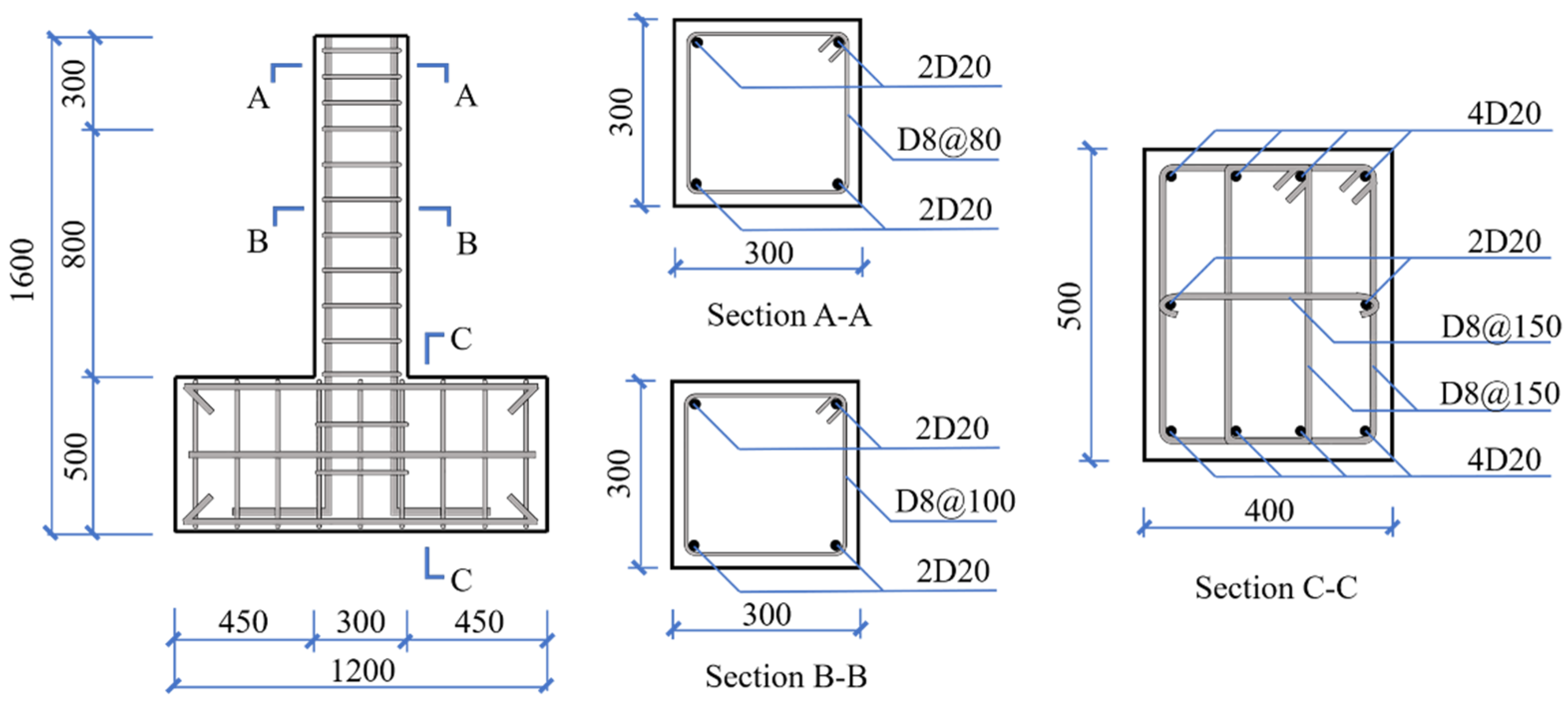
The geometric dimensions and reinforcement of each specimen are the same, as shown in
Figure 2. In addition, to avoid local damage to the top of the column during the loading process, the stirrups within 300 mm of the top of the column were densified.
2.3. Test Setup and Measurements
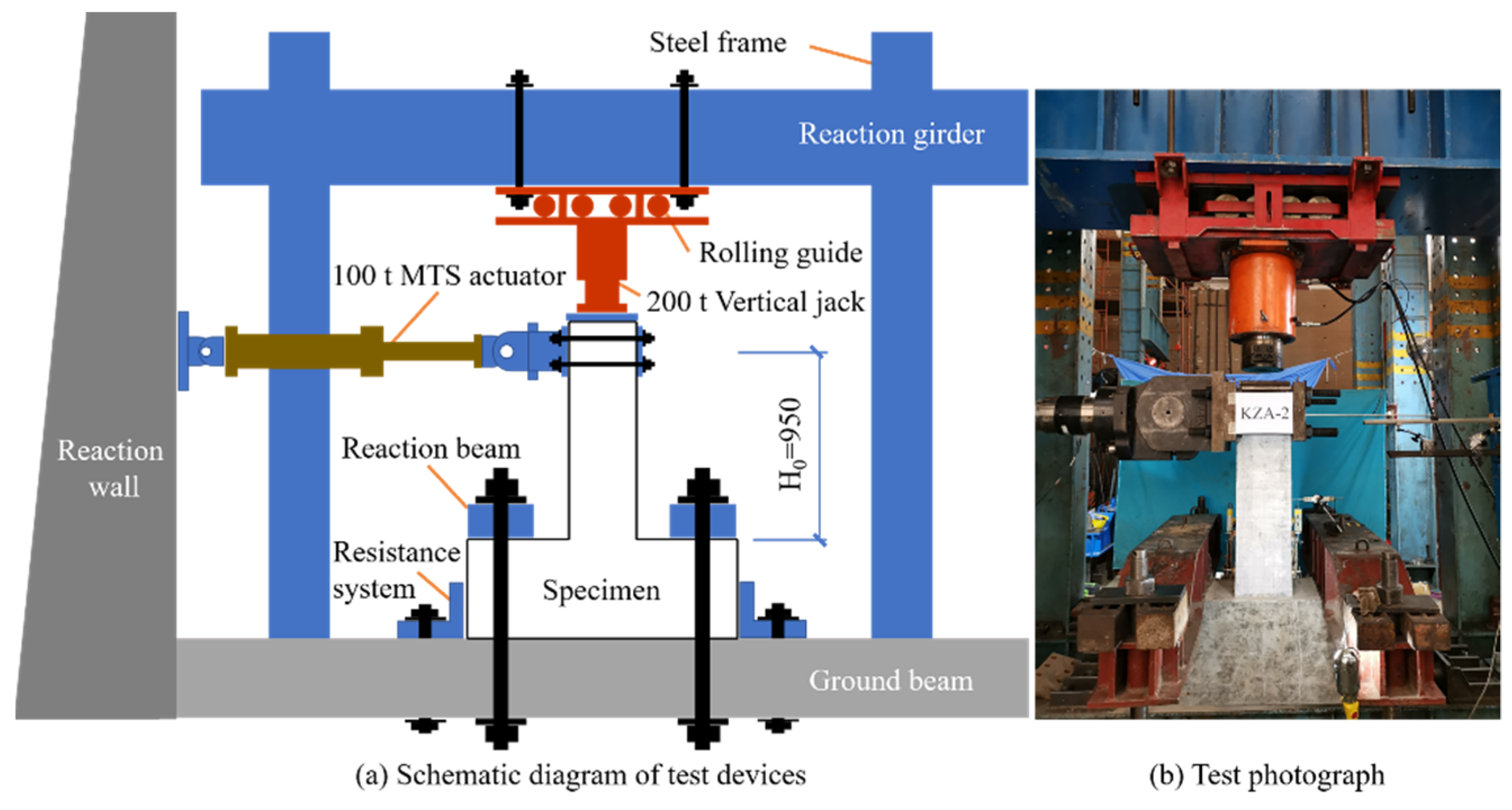
The specimen is fixed on the ground beam by bolts; the loading device is shown in
Figure 3. The axial load is applied by the 200 t vertical jack, and its value remains unchanged during the whole loading process, while the horizontal cyclic load is applied by the 100 t MTS electro-hydraulic servo actuator and the load is recorded automatically. The vertical jack is connected with the reaction girder through the directional support. Due to the small friction coefficient of the roller, it can ensure that the jack moves horizontally with the specimen without relative displacement [
29]. When loading, the axial load is first applied, and then the horizontal cyclic load is applied [
30].
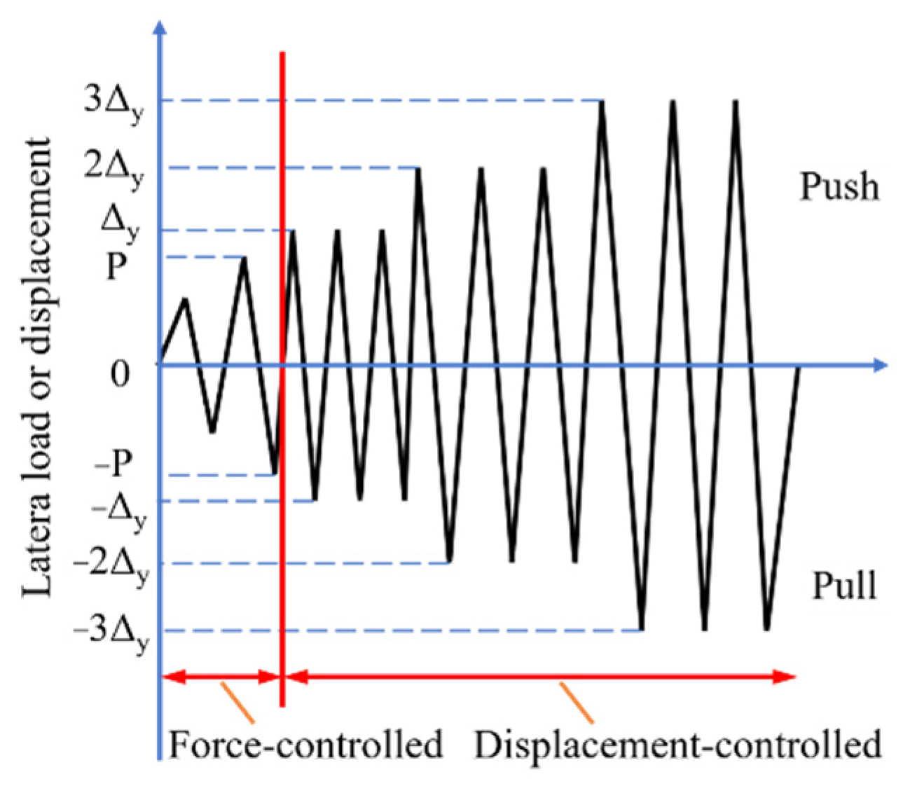
The load-deformation double control method is used for horizontal cyclic load [
31], and the loading steps are shown in
Figure 4. Before the specimen has yielded, the force-controlled mode is adopted, the increment is 10 kN, and each load is pushed and pulled once. After the specimens yields, the displacement-controlled method is used for loading, and the yield displacement (Δ
y) is used as the increment, and each displacement is repeated for three cycles [
32]. When the load drops to 85% of the peak load, it indicates that the specimen has been damaged [
33].
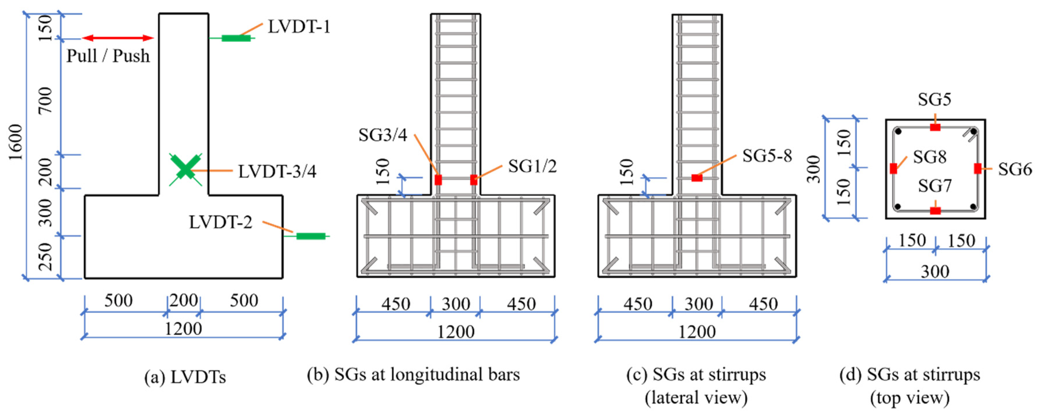
The layout of the linear variable differential transducers (LVDTs) on the surface of the specimen is shown in
Figure 5a. The displacement at the loading point of the column top is measured by LVDT-1, and LVDT-2 is used to record the horizontal displacement of the base to correct the column top displacement. LVDT-3/4 are two orthogonally arranged transducers used to measure the shear deformation in the plastic hinge area of the specimen [
34]. The strains of the longitudinal bars and stirrups were measured by strain gauges (SG) glued to the surface of reinforcement, and the layout is shown in
Figure 5b–d.
3. Results
3.1. General Observations and Failure Modes
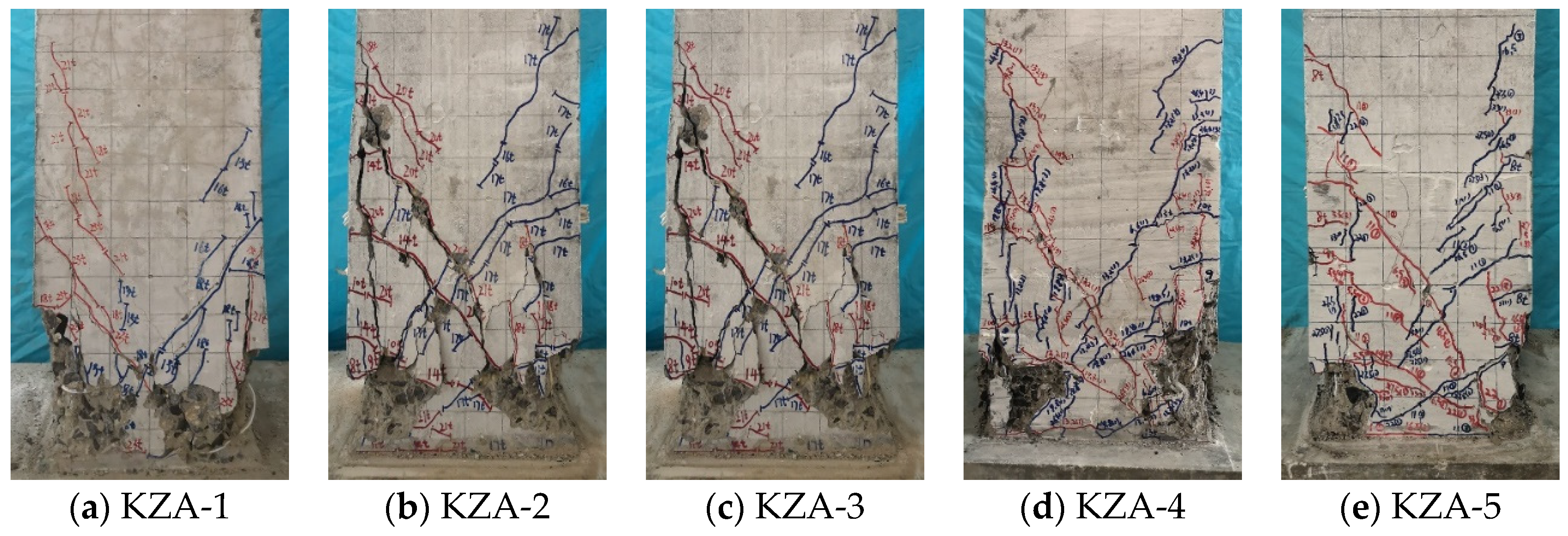
The failure process of CGC specimens with different replacement ratios is similar to that of the NAC specimen, and they all go through four stages: cracking, yield, ultimate, and failure. The typical specimen KZA-5 was used as an example to illustrate the failure process.
When the load P = 80 kN, a horizontal crack with a length of about 50 mm was first observed at a distance of 150 mm from the base of the column. After continuing to load for a period of time, the test loading was changed from force-controlled to displacement-controlled. When the displacement Δ = 6.0 mm, at a distance of 300 mm from the base of the column, the original horizontal crack expanded to form an oblique crack about 80 mm, the direction of which was roughly at a 45-degree angle to the horizontal. When the displacement Δ = 12.0 mm, a vertical crack with a length of about 100 mm appeared at a distance of 400 mm from the base of the column. When the displacement Δ = 14.8 mm, the bearing capacity of the specimen reached the peak load. Continuing to load, the concrete cover at the column foot peeled off. When the displacement Δ = 32.1 mm, the bearing capacity decreased to 85% of the maximum load, indicating that the specimen was damaged, and the loading stopped. The failure modes of specimens are shown in
Figure 6.
It can be seen from
Figure 6 that many oblique cracks appear directly on the surface of the NAC column after cyclic load, while the oblique cracks on the surface of CGC specimens are mainly formed by the expansion of horizontal cracks. The main reason for this phenomenon is that compared with NAC, the elastic modulus of CGC is small, so the bending deformation of the CGC specimen is greater than that of the NAC specimen at the initial stage of loading, resulting in more horizontal bending cracks on the surface of the CGC specimen, and then further expand into oblique cracks during the cyclic action of load.
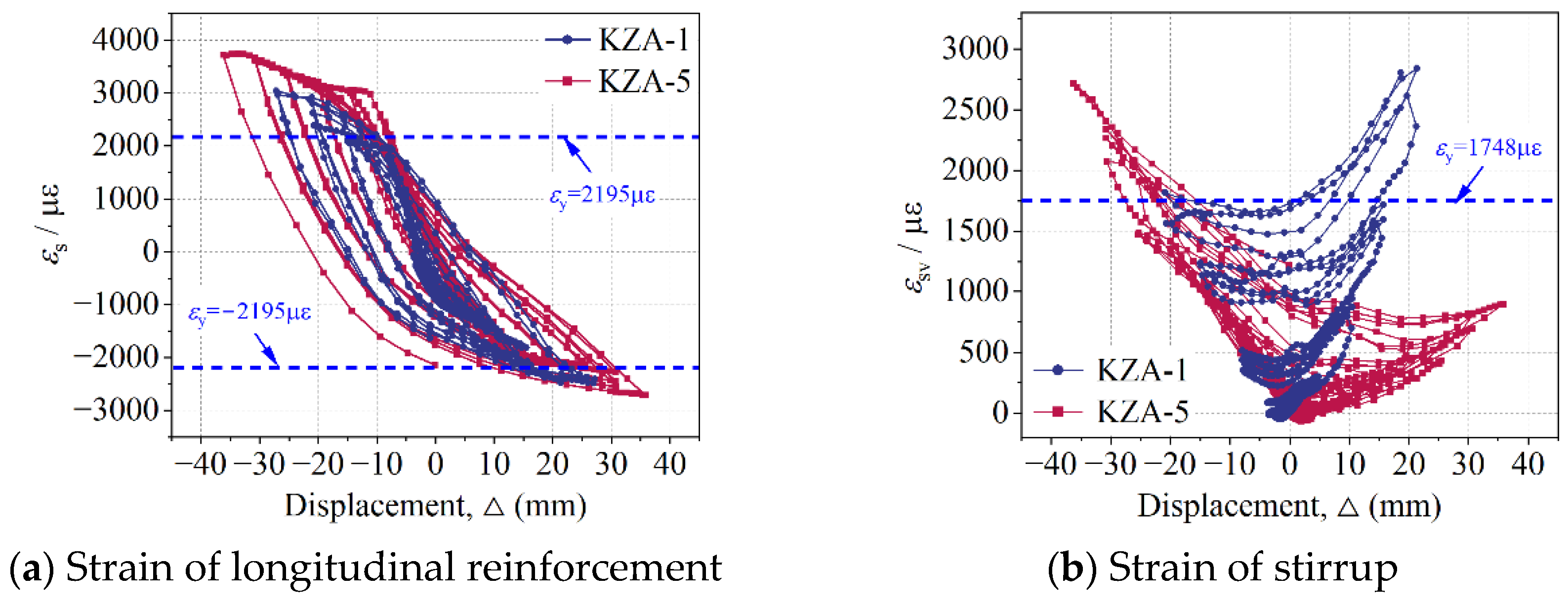
According to whether the reinforcement yields after the column is damaged, there are three failure modes of the column under cyclic loading, including bending, shear, and bending–shear [
35]. The reinforcement strains of typical specimens KZA-1 and KZA-5 are plotted in
Figure 7. According to the measured yield strain of reinforcement in
Table 3, the longitudinal reinforcement and stirrup in the NAC and CGC columns yielded before the specimen was damaged, and then the concrete was crushed. Therefore, the failure mode of CGC specimens with different replacement ratios is consistent with that of the NAC specimen, which belongs to bending–shear failure.
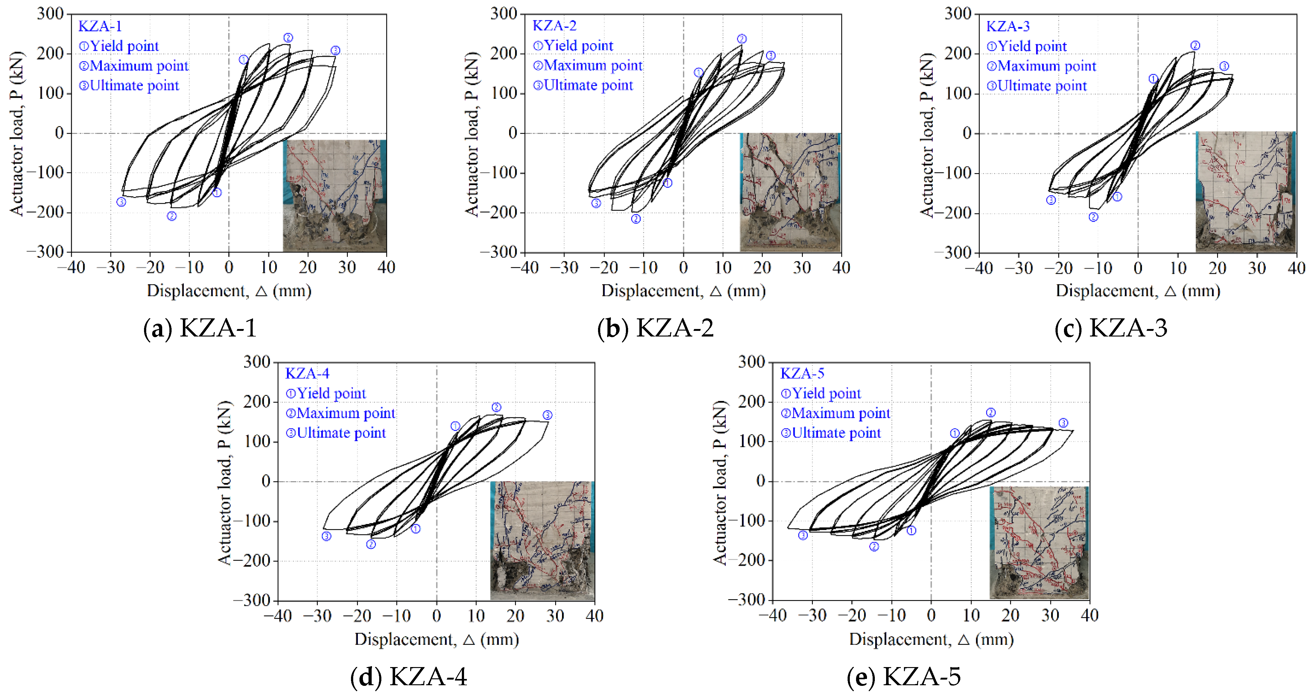
3.2. Hysteretic Curves
The hysteretic curves of specimens are shown in
Figure 8. Affected by the coal gangue coarse aggregate, compared with the NAC specimen, the bearing capacity of the CGC specimens decreased by 1.7%, 4.6%, 24.7%, and 26.9% with the increase in the coal gangue replacement ratio. Moreover, compared with the NAC specimen, the biggest difference in the hysteresis curve of the CGC specimen is that the unloading curve is flatter, resulting in a significant reduction in the area enclosed by the hysteresis curve, the residual deformation after complete unloading is small, and the recovery deformation lag phenomenon is not significant.
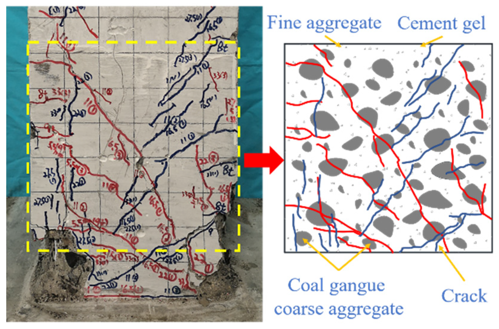
Observation of the crack interface for the specimen during loading showed that the different crack interface characteristics of the CGC specimen and NAC specimen are the main reasons for the difference in hysteresis performance.
Figure 9 is the typical crack interface of the CGC specimen. Due to the low strength of CGCA, it cannot prevent the cracks from propagating, resulting in the crack directly passing through the CGCA. Therefore, the crack interface of the CGC specimen is relatively linear, the mechanical bite force between cracks is poor, and the crack can be closed quickly after unloading, resulting in poor energy consumption and small residual deformation of the specimen.
However, it is worth noting that due to the large deformation of CGCA, the higher the replacement ratio of the CGC specimen, the more the cyclic times of the hysteretic curve, and the larger the total area under the hysteretic cycle. Therefore, it can be found from
Figure 8 that the energy dissipation of the CGC specimen with a higher replacement ratio is better.
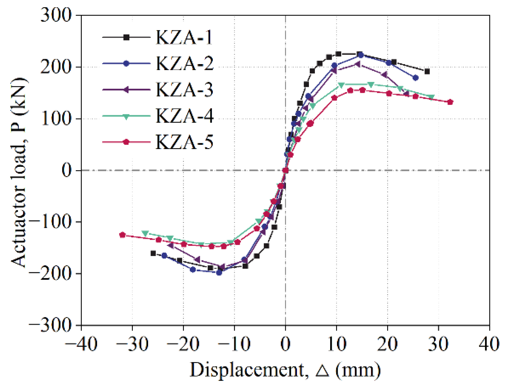
3.3. Skeleton Curves
The skeleton curve of each specimen is obtained by connecting the trajectories of the maximum load reached by each cyclic loading [
36], as shown in
Figure 10.
Obviously, in the ascending section of the skeleton curve, the stiffness of CGC specimens is less than that of NAC specimens due to the influence of CGCA. In the descending section of the skeleton curve, the curves of specimens KZA-1, KZA-4, and KZA-5 are relatively soft, while the curves of specimens KZA-2 and KZA-3 are relatively steep. Obviously, the ductility of CGC specimens with a high replacement ratio is close to that of the NAC specimen, and is significantly higher than that of CGC specimens with low replacement ratio.
3.4. Displacement Ductility
The seismic performance of a structure depends not only on the bearing capacity of the component, but also on its deformation performance to a large extent. The ductility coefficient (
μ) is an important index to evaluate the deformation performance of specimens [
37], and the calculation formula is shown in Equation (1).
where Δ
u is the displacement when the load is reduced to 85% of the peak load; Δ
y is the yield displacement of the specimen, which is calculated by the energy equivalent method [
38].
According to the ductility coefficient of specimens in
Table 5, a number of findings can be reported. (a) Compared with KZA-1, the yield displacements of KZA-2, KZA-3, KZA-4, and KZA-5 are increased by 5.2%, 14.9%, 19.4%, and 30.0%, while the ductility coefficients are reduced by 28.6%, 24.4%, 12.6%, and 8.2%, indicating that the deformation characteristics of CGC specimens have a large deformation ability before yield but a poor deformation ability after yield. (b) Compared with KZA-2, the ultimate displacements of KZA-3, KZA-4, and KZA-5 are increased by 15.8%, 38.8%, and 59.1%, and the ductility coefficients are increased by 5.9%, 22.3%, and 28.5%, indicating that the deformation capacity of CGC specimens is positively correlated with the coal gangue replacement ratio. Combined with the hysteretic curve of specimens (see
Figure 8), it can be found that due to the large deformation of CGCA, the hysteretic performance of CGC specimens with high replacement ratio is improved, so the deformation performance is increased. (c) The ductility coefficient of CGC specimens is between 3.05–3.92, which is lower than that of the NAC specimen (
μ = 4.27), but it meets the requirement that the ductility coefficient of reinforced concrete seismic structure is not less than 3.0, indicating that the CGC specimen has good ductility performance under cyclic load.
3.5. Energy Dissipation Capacity
The area under the hysteretic curve reflects the energy dissipated by the specimen under the cyclic loading [
39]. The relationship between the energy dissipation of each specimen and the displacement is shown in
Figure 11.
Due to the damage of CGCA at the crack interface of CGC specimen (see
Figure 9), the energy consumption of CGC specimen is less than that of NAC specimen whether it is the energy consumption of single cyclic loading or the total energy consumption. Compared with KZA-1, the energy dissipation of the CGC specimens with different replacement ratios decreased by 50.3%, 37.7%, 31.2%, and 12.8%.
However, it is worth noting that the deformation capacity of CGC specimen is improved due to the large deformation of coal gangue coarse aggregate (see
Table 5). Therefore, compared with KZA-2, the total energy dissipation of KZA-3, KZA-4, and KZA-5 increased by 25.2%, 38.2%, and 75.4%, respectively.
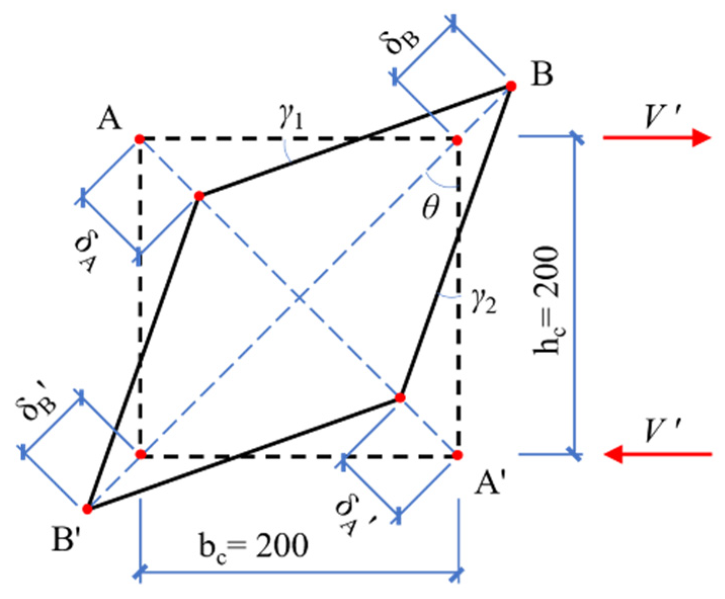
3.6. Shear Deformation
Through the two transducers (LVDT-3,4) arranged in
Figure 5, the deformation at the plastic hinge area of the specimen under cyclic load can be measured. The shear deformation (
γ) calculation diagram is shown in
Figure 12, and the calculation formulas are shown in Equations (2) and (3).
where h
c and b
c represent the measured height and width of the plastic hinge region, as shown in
Figure 12;
is the average deformation along the diagonal direction; δ
A +
δ′
A and
δB +
δ′
B are measured by LVDT-3 and LVDT-4.
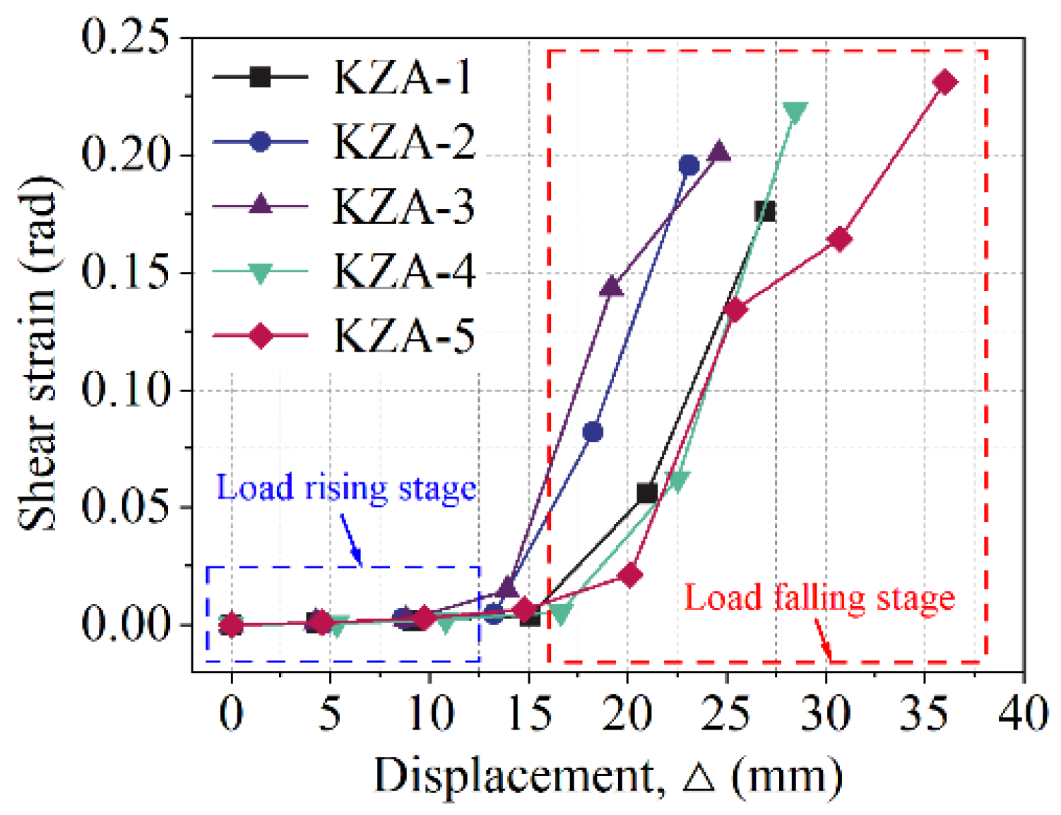
The shear deformation at the plastic hinge area of each specimen is shown in
Figure 13, and its value is the average value in the push and pull directions. In terms of the overall trend, the development of the shear deformation of the specimen can be divided into two stages: the load rising stage and the load falling stage.
In the load rising stage, the overall deformation of the specimen is small, and the oblique cracks on the surface of the specimen have not significantly expanded, so the shear deformation of each specimen is very small. The shear deformation curves of the CGC specimens and NAC specimens roughly coincide, and the coal gangue coarse aggregate has little effect on the shear deformation of the specimen.
In the load falling stage, due to the continuous expansion of oblique cracks on the surface of the specimen, the shear deformation of each specimen increases rapidly with the increase in displacement until the specimen is damaged. Compared with NAC specimens, CGC specimens have greater shear deformation because there is a large amount of damage of coal gangue coarse aggregate at the crack interface, resulting in the reduction in mechanical bite force at the crack interface. When the specimens are damaged, the shear deformation of KZA-2, KZA-3, KZA-4, and KZA-5 increased by 10.9%, 13.7%, 24.2%, and 31.2%, respectively, compared with KZA-1.
The destruction of coal gangue coarse aggregate leads to the increase in the shear deformation of the CGC specimen, and the increase in the shear deformation of CGC specimen will further reduce the energy dissipation capacity of the crack interface. Therefore, it is suggested that increasing the stirrup ratio in CGC specimens can not only effectively restrict the deformation of CGC and enhance the friction at the crack interface, but also improve the hysteretic performance and energy dissipation capacity of CGC specimens, which is an effective way to improve the seismic performance of CGC specimens. Moreover, the existing research [
40] shows that the use of the steel section will effectively improve the seismic performance of concrete structures. Therefore, in addition to appropriately increasing the reinforcement ratio of coal gangue concrete, it can also be considered to arrange the steel section in the coal gangue concrete to improve the seismic performance of the coal gangue concrete structure.
It should be noted that this paper mainly studies the mechanical behavior of coal gangue concrete frame joints under repeated load, and whether the addition of coal gangue coarse aggregate will affect the corrosion resistance of reinforcement [
41]; the durability of concrete remains to be further studied.
4. Conclusions
Using solid waste coal gangue as coarse aggregate can significantly reduce the mining of natural aggregates and help realize the sustainable development of construction engineering. Through the cyclic loading test of five concrete frame columns with different coal gangue replacement ratios, the following conclusions can be drawn.
The coal gangue coarse aggregate cannot block the propagation of cracks, resulting in the decrease in friction at the crack interface. Therefore, CGC specimens have two typical characteristics under cyclic loads: most of the deformation can be recovered quickly after each unloading, and the residual deformation of the specimen is small; the deformation of the specimen is large before yield, while the deformation capacity is poor after yield.
Both CGC and NAC specimens show a bending–shear type of failure, but affected by the coal gangue coarse aggregate, the ductility coefficients and total energy consumption of CGC specimens are reduced by 8.2–28.6% and 12.8–50.3%, respectively compared with KZA-1.
Affected by the large deformation of coal gangue coarse aggregate, the CGC specimens with higher replacement ratio have better seismic performance. Compared with KZA-2, the ductility coefficients of KZA-3, KZA-4, and KZA-5 increased by 15.8%, 38.8%, 59.1%, and the total energy consumption increased by 25.2%, 38.2%, and 75.4%, respectively.
Compared with KZA-1, the shear deformation at the plastic hinge area of CGC specimens increased by 10.9–31.2%. Larger shear deformation directly increases the width of the diagonal crack, which is also one of the reasons for the decrease in energy dissipation capacity of the CGC specimens. In the design, it is suggested to appropriately increase the stirrup ratio of the CGC specimen to improve its seismic performance.
In general, although the seismic performance of CGC specimens is reduced by the influence of coal gangue coarse aggregate compared with NAC specimens, the displacement ductility coefficient of CGC specimens with different replacement ratios is between 3.05–3.92, indicating that CGC specimens can be applied to structures in areas with seismic fortification requirements.
Author Contributions
Conceptualization, H.L. and G.B.; methodology, H.L. and G.B.; software, H.L. and Y.G.; validation, G.B.; formal analysis, G.B.; investigation, F.Y. and Y.G.; resources, G.B.; data curation, H.L., F.Y. and K.Z.; writing—original draft preparation, H.L.; writing—review and editing, G.B.; visualization, G.B.; supervision, G.B.; project administration, G.B.; funding acquisition, G.B. All authors have read and agreed to the published version of the manuscript.
Funding
This research was funded by the National Natural Science Foundation of China, grant number 52078410; Shaanxi Provincial Science and Technology Plan Achievement Promotion Project, grant number 2020CGHJ-017; and Key Laboratory Project of Shaanxi Provincial Department of Education, grant number 20JS071.
Institutional Review Board Statement
Not applicable.
Informed Consent Statement
Not applicable.
Data Availability Statement
Not applicable.
Conflicts of Interest
The authors declare no conflict of interest.
References
- Querol, X.; Izquierdo, M.; Monfort, E.; Álvarez, E.; Font, O.; Moreno, T.; Alastuey, A.; Zhuang, X.; Lu, W.; Wang, Y. Environmental characterization of burnt coal gangue banks at Yangquan, Shanxi Province, China. Int. J. Coal Geol. 2008, 75, 93–104. [Google Scholar] [CrossRef]
- Wang, C.; Ni, W.; Zhang, S.; Wang, S.; Gai, G.; Wang, W. Preparation and properties of autoclaved aerated concrete using coal gangue and iron ore tailings. Constr. Build. Mater. 2016, 104, 109–115. [Google Scholar] [CrossRef]
- Li, D.; Song, X.; Gong, C.; Pan, Z. Research on cementitious behavior and mechanism of pozzolanic cement with coal gangue. Cem. Concr. Res. 2006, 36, 1752–1759. [Google Scholar] [CrossRef]
- Zhang, Y.; Ling, T. Reactivity activation of waste coal gangue and its impact on the properties of cement-based materials–A review. Constr. Build. Mater. 2020, 234, 117424. [Google Scholar] [CrossRef]
- Okagbue, C.; Ochulor, O. The Potential of Cement-Stabilized Coal-Reject as a Construction Material. Bull. Eng. Geol. Environ. 2007, 66, 143–151. [Google Scholar] [CrossRef]
- Jabło´nska, B.; Kityk, A.; Busch, M.; Huber, P. The structural and surface properties of natural and modified coal gangue. J. Environ. Manag. 2017, 190, 80–90. [Google Scholar] [CrossRef]
- Moghadam, M.; Ajalloeian, R.; Hajiannia, A. Preparation and application of alkali-activated materials based on waste glass and coal gangue: A review. Constr. Build. Mater. 2019, 221, 84–98. [Google Scholar] [CrossRef]
- Dong, Z.; Xia, J.; Fan, C.; Gao, J. Activity of calcined coal gangue fine aggregate and its effect on the mechanical behavior of cement mortar. Constr. Build. Mater. 2015, 100, 63–69. [Google Scholar] [CrossRef] [Green Version]
- Zaben, A.; Maslehuddin, M.; Omar, A.; Al-Dulaijan, S. Influence of mix composition on the properties of recycled aggregate concrete. Struct. Concr. 2021, 22, 2939–2951. [Google Scholar] [CrossRef]
- Piccinali, A.; Diotti, A.; Plizzari, G.; Sorlini, S. Impact of Recycled Aggregate on the Mechanical and Environmental Properties of Concrete: A Review. Materials 2022, 15, 1818. [Google Scholar] [CrossRef]
- Li, C.; Wan, J.; Sun, H. Investigation on the activation of coal gangue by a new compound method. J. Hazard. Mater. 2010, 179, 515–520. [Google Scholar] [CrossRef] [PubMed]
- Makul, N.; Fediuk, R.; Amran, M.; Zeyad, A.M.; de Azevedo, A.R.G.; Klyuev, S.; Vatin, N.; Karelina, M. Capacity to Develop Recycled Aggregate Concrete in South East Asia. Buildings 2021, 11, 234. [Google Scholar] [CrossRef]
- Xu, D.; Yang, Y.; Chen, Z. Experimental Study and Damage Model on the Seismic Behavior of Reinforced Concrete L-Shaped Columns under Combined Torsion. Appl. Sci. 2020, 10, 7008. [Google Scholar] [CrossRef]
- Bravo, M.; Duarte, A.P.C.; de Brito, J.; Evangelista, L.; Pedro, D. On the Development of a Technical Specification for the Use of Fine Recycled Aggregates from Construction and Demolition Waste in Concrete Production. Materials 2020, 13, 4228. [Google Scholar] [CrossRef] [PubMed]
- Silva, F.A.N.; Delgado, J.M.P.Q.; Azevedo, A.C.; Lima, A.G.B.; Vieira, C.S. Preliminary Analysis of the Use of Construction Waste to Replace Conventional Aggregates in Concrete. Buildings 2021, 11, 81. [Google Scholar] [CrossRef]
- Díaz, M.; Almendro-Candel, M.B.; Blanco, D.; Jordan, M.M. Aggregate Recycling in Construction: Analysis of the Gaps between the Chilean and Spanish Realities. Buildings 2019, 9, 154. [Google Scholar] [CrossRef] [Green Version]
- Marsh, E. Civil infrastructure systems materials research support at the National Science Foundation. Cem. Concr. Comp. 2003, 25, 575–583. [Google Scholar] [CrossRef]
- Gao, S.; Zhang, S.; Guo, L. Application of Coal Gangue as a Coarse Aggregate in Green Concrete Production: A Review. Materials 2021, 14, 6803. [Google Scholar] [CrossRef]
- Zhang, Y.; Wang, Q.; Zhou, M.; Fang, Y.; Zhang, Z. Mechanical properties of concrete with coarse spontaneous combustion gangue aggregate (SCGA): Experimental investigation and prediction methodology. Constr. Build. Mater. 2020, 255, 119337. [Google Scholar] [CrossRef]
- Li, S.; Zhou, M.; Zhang, L. Properties of spontaneous combustion coal gangue coarse aggregate and its influence on concrete. J. Build. Mater. 2020, 23, 334–340, 380. [Google Scholar]
- Wang, Q.; Li, Z.; Zhang, Y.; Zhang, H.; Zhou, M.; Fang, Y. Influence of coarse coal gangue aggregates on elastic modulus and drying shrinkage behaviour of concrete. J. Build. Eng. 2020, 32, 101748. [Google Scholar] [CrossRef]
- Liu, H.; Xu, Q.; Wang, Q.; Zhang, Y. Prediction of the elastic modulus of concrete with spontaneous-combustion and rock coal gangue aggregates. Structures 2020, 28, 774–785. [Google Scholar] [CrossRef]
- Zhou, M.; Dou, Y.; Zhang, Y.; Zhang, Y.; Zhang, B. Effects of the variety and content of coal gangue coarse aggregate on the mechanical properties of concrete. Constr. Build. Mater. 2019, 220, 386–395. [Google Scholar] [CrossRef]
- Guan, X.; Qiu, J.; Song, H.; Qin, Q.; Zhang, C. Stress–strain behaviour and acoustic emission characteristic of gangue concrete under axial compression in frost environment. Constr. Build. Mater. 2019, 220, 476–488. [Google Scholar] [CrossRef]
- Qiu, J.; Zhou, Y.; Vatin, N.; Guan, X.; Sultanov, S.; Khemarak, K. Damage constitutive model of coal gangue concrete under freeze-thaw cycles. Constr. Build. Mater. 2020, 264, 120720. [Google Scholar] [CrossRef]
- Bai, G.; Zhu, C.; Wang, J. Experimental study on shear behavior of coal gangue concrete beams. J. Build. Struct. 2020, 41, 49–55. [Google Scholar] [CrossRef]
- Wang, Q.; Li, Z.; Zhou, M. Effects of spontaneous-combustion coal gangue aggregate (SCGA) replacement ratio on flexural behavior of SCGA concrete beams. J. Build. Struct. 2020, 41, 64–74. [Google Scholar] [CrossRef]
- Huda, S.; Alam, M. Mechanical behavior of three generations of 100% repeated recycled coarse aggregate concrete. Constr. Build. Mater. 2014, 65, 574–582. [Google Scholar] [CrossRef]
- Choi, M.; Lee, C. Seismic Behavior of Existing Reinforced Concrete Columns with Non-Seismic Details under Low Axial Loads. Materials 2022, 15, 1239. [Google Scholar] [CrossRef]
- Hashemi, B.; Bonab, A. Experimental investigation of the behavior of laced columns under constant axial load and cyclic lateral load. Eng. Struct. 2013, 57, 536–543. [Google Scholar] [CrossRef]
- Karen, E.; Caballero-Morrison, J.; Bonet, J.; Pedro, S. An experimental study of steel fiber-reinforced high-strength concrete slender columns under cyclic loading. Eng. Struct. 2013, 57, 565–577. [Google Scholar] [CrossRef]
- Hyun, J.; Bang, J.; Lee, B.; Kim, Y. Effects of the Replacement Length of Concrete with ECC on the Cyclic Behavior of Reinforced Concrete Columns. Materials 2021, 14, 3542. [Google Scholar] [CrossRef] [PubMed]
- Cassese, P.; Menna, C.; Occhiuzzi, A.; Asprone, D. Experimental Behavior of Existing RC Columns Strengthened with HPFRC Jacket under Concentric and Eccentric Compressive Load. Buildings 2021, 11, 521. [Google Scholar] [CrossRef]
- El-Mandouh, M.; Omar, M.; Elnaggar, M.; Abd El-Maula, A. Cyclic Behavior of High-Strength Lightweight Concrete Exterior Beam-Column Connections Reinforced with GFRP. Buildings 2022, 12, 179. [Google Scholar] [CrossRef]
- Wang, J.; Yi, X.; Liu, Q.; Fang, X. Seismic Performance of Steel-Reinforced Concrete Columns with Q690 High-Strength Steel. Materials 2022, 15, 2979. [Google Scholar] [CrossRef] [PubMed]
- Shi, K.; Zhang, M.; Zhang, T.; Li, P.; Zhu, J.; Li, L. Seismic Performance of Steel Fiber Reinforced High–Strength Concrete Beam–Column Joints. Materials 2021, 14, 3235. [Google Scholar] [CrossRef]
- Rodrigues, H.; Arêde, A.; Varum, H.; Costa, A.G. Experimental evaluation of rectangular reinforced concrete column behaviour under biaxial cyclic loading. Earthq. Eng. Struct. Dyn. 2013, 42, 239–259. [Google Scholar] [CrossRef]
- Jiuru, T.; Chaobin, H.; Kaijian, Y.; Yongcheng, Y. Seismic behavior and shear strength of framed joint using steel–fiber reinforced concrete. J. Struct. Eng. 1992, 118, 341–358. [Google Scholar] [CrossRef]
- Chopra, A. Dynamics of Structures: Theory and Applications to Earthquake Engineering; Prentice Hall: Hoboken, NJ, USA, 2017. [Google Scholar]
- Montava, I.; Irles, R.; Pomares, J.C.; Gonzalez, A. Experimental Study of Steel Reinforced Concrete (SRC) Joints. Appl. Sci. 2019, 9, 1528. [Google Scholar] [CrossRef] [Green Version]
- Bautista, A.; Pomares, J.C.; González, M.N.; Velasco, F. Influence of the microstructure of TMT reinforcing bars on their corrosion behavior in concrete with chlorides. Constr. Build. Mater. 2019, 229, 116899. [Google Scholar] [CrossRef] [Green Version]
| Publisher’s Note: MDPI stays neutral with regard to jurisdictional claims in published maps and institutional affiliations. |
© 2022 by the authors. Licensee MDPI, Basel, Switzerland. This article is an open access article distributed under the terms and conditions of the Creative Commons Attribution (CC BY) license (https://creativecommons.org/licenses/by/4.0/).


