Article

Experiment Study on the Hysteretic Performance of a Novel Replaceable Beam-to-Column Joint with Energy-Dissipating Steel Hinge

1
College of Civil Engineering, Fuzhou University, Fuzhou 350108, China
2
College of Civil Engineering, Fujian University of Technology, Fuzhou 350118, China
3
Fujian Provincial Erjian Construction Group Corp., Ltd., Fuzhou 350001, China
*
Authors to whom correspondence should be addressed.
Buildings 2022, 12(8), 1180; https://doi.org/10.3390/buildings12081180
Submission received: 7 July 2022 / Revised: 3 August 2022 / Accepted: 3 August 2022 / Published: 7 August 2022
(This article belongs to the Special Issue Improvement Technology on Building Seismic Toughness)

Abstract

:
A novel precast replaceable beam-to-column joint with energy-dissipating steel hinges was proposed for the connection of precast structures to improve the seismic performance and post-earthquake resilience. The proposed joint was installed in the predetermined plastic hinge region at beams and the flange segments of the proposed joint were weakened to achieve damage concentration. Cyclic loading tests were conducted on the proposed joint and the steel sleeve confined concrete joint to study the hysteretic performance, including failure mode, load–displacement curves, ductility, and energy-dissipation capacity. Moreover, the hystertic performance of the damage-repaired proposed joint was investigated to verify the post-earthquake resilience. Results demonstrated that the proposed joints could develop favorable failure mode with the necking rupture of the weakened steel plate in steel hinge. The damage of the proposed joint was concentrated in the energy-dissipating hinges while no serious damage was observed in the precast framing components, achieving the objective of damage concentration. Compared with steel sleeve confined concrete joint, the hysteresis curve of proposed joint was more plump while an obvious pinching effect was observed in the steel-confined concrete joint. The bearing capacity and energy-dissipation capacity of the proposed joint were about 1.25 times and 1.55 times of that for the steel sleeve confined concrete joint, respectively. In addition, the hysteretic performance of the repaired specimen was identical to the original one, with the desired failure mode caused by the fracture of the steel hinge. It was noted that the hysteretic performance of the repaired joint was better than the steel sleeve confined concrete joint. The bearing capacity was recovered at up to 96.6% of the original joint while the energy-dissipation capacity was recovered at 96.1%, indicating that the proposed joint achieved the post-earthquake resilience to a great extent.

1. Introduction

Industrialization of the construction industry promotes the development of precast reinforced concrete structures, which have entered the rapid growth stage. Precast reinforced concrete structures can improve construction quality, construction efficiency, and economic benefit, which are conducive to environmental protection [1,2]. However, the mechanical properties of the connection area of the prefabricated members always affect the integrity and seismic performance of the fabricated structure, which is more likely to be damaged and result in the collapse of the whole structure under the action of earthquakes [3,4]. Therefore, the research and development of new beam–column connections with the required mechanical properties is of great significance to improve the seismic performance of prefabricated concrete structures [5,6,7,8].
In-depth research works have been conducted on the fabricated beam–column connections or various connection methods for the connection of precast components, such as post-cast precast concrete joints [9,10], bolted connection of prefabricated members [11,12,13], and prestressed prefabricated joint [14,15,16,17]. Bahrami et al. [18] presented two kinds of bending connection precast joints, and carried out numerical research on the mechanical behavior under cyclic loading. The results showed that plastic hinge formed at the precast beam of the frame with two kinds of flexural connection precast joints led to an improved failure mode of bending. Girgin et al. [19] tested the mechanical behavior of five precast hybrid half-scale specimens, and it was observed that the maximum strain developed in the beam bottom flexural reinforcement played an important role in the overall behavior of the connections. Nzabonimpa et al. [20] presented a new assembled mechanical joint with removing the laminate, and established experimental and numerical studies of mechanical properties of joint structures. To improve energy consumption for precast beam–column connection, Tartaglia and Ferrante [21,22] acted on beam–column joints with friction dampers to control plastic deformation and improve node energy consumption.
Moreover, research on improving the seismic performance of precast reinforced concrete structures with prefabricated beam–column connections characterized by plastic damage has attracted more and more attention [23]. The hysteretic performance and damage characteristics of prefabricated, prestressed concrete frame systems with slightly pressed joints were studied [24], and the results demonstrated that slightly pressed joints were conducive to the control of deformation capacity and cracking. Wang et al. [25] arranged a replaceable low-yield-point steel bar in the assembled node to improve energy-dissipation capacity and control damage. Li et al. [26] investigated fabricated RC beam–column plastic controllable steel joint specimens to effectively control concrete damage. Zheng et al. [27] proposed a novel type of steel reciprocating bending energy-dissipation hinge connected by pin shaft to achieve beam-end energy dissipation and plastic hinge outward migration. Teng et al. [28] proposed a novel prefabricated beam-to-column steel joint and compared its hysteretic performance with a monolithic joint. The results showed that the use of buckling energy-dissipation segments was beneficial for concentrating the plastic deformation. Ertas et al. [29] experimentally investigated the performance of four types of precast concrete joints, which showed that, compared with other precast concrete joints, bolted concrete joints had the best ductility, strength, and energy-dissipation capacity. Li et al. [30] developed prefabricated steel joint precast concrete structures to replace cast-in-situ concrete beam-to-column joints. It was found experimentally that this joint exhibited better hysteretic performance and higher energy dissipation and ductility than a monolithic joint. A new hybrid beam–column connection was proposed for precast concrete structures, and the seismic behavior including hysteretic curves, skeleton curves, and dissipation capacity were studied through experimental and numerical study [31]. Moreover, it was also verified that the energy-dissipation capacity of the fabricated beam-to-column joint could be effectively enhanced by employing a friction device or dampers [32,33,34].
In this paper, a new kind of precast replaceable beam-to-column joint with an energy-dissipating steel hinge was proposed, which can be applied to the connection of precast reinforced concrete structures to improve seismic performance. In addition, through the rational design of the proposed joint, the accumulated plastic damage was concentrated in the energy-dissipating steel hinge and prevented the precast beams and columns from serious damage, improving the post-earthquake resilience performance of the precast reinforced concrete structures. By replacing the damaged upper and lower energy-dissipation steel plates in steel hinge, the proposed joints can be repaired conveniently and efficiently so as to restore the working performance. The hysteretic properties such as failure mode, load–displacement curves, stiffness degradation, and energy-dissipation capacity of the proposed joints were studied and compared with those of prefabricated steel sleeve confined concrete joints. Besides, the post-earthquake resilience performance was discussed by the comparison between the repaired specimen and original specimen.

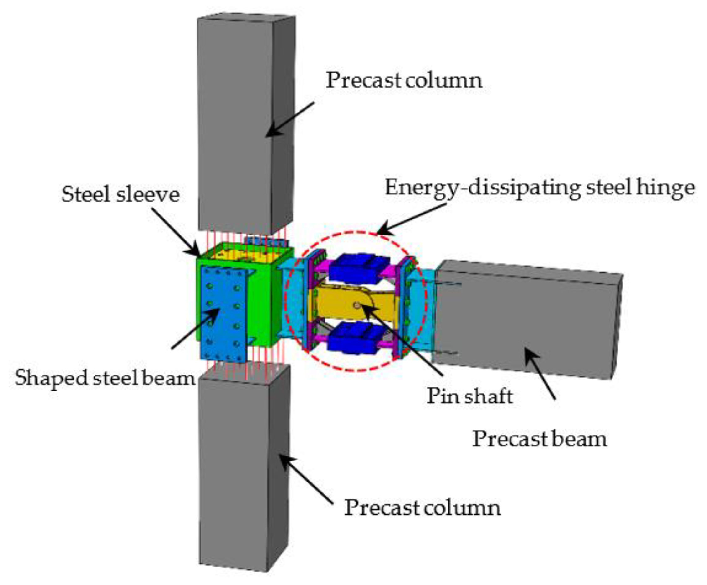
2. Precast Replaceable Beam-to-Column Joint with Energy-Dissipating Steel Hinge

The configurations of the precast replaceable beam-to-column joint with an energy-dissipating steel hinge are shown in Figure 1. The proposed joint is composed of precast columns, precast beams with embedded steel beam segments, a confined steel sleeve for the core joint, and an energy-dissipating steel hinge. The joint core area was confined with a steel sleeve, with horizontal end plates to enhance the shear resistance. The steel sleeve was welded to a short cantilever beam segment, and then connected to the steel hinge by high-strength bolts. The longitudinal bars of the precast beam were welded to the steel beam with holed-end plates, and then the precast beam was also bolted to the steel hinge through the embedded steel beam segment. The grouting sleeves were embedded at the end of the rebars in the upper precast column, while the upper and lower plate stiffeners inside the steel sleeve were designed with holes to install reinforcements in the bottom column. The energy-dissipating steel hinge consisted of a flange energy-dissipation steel plate and a web-mechanical hinge with a pin shaft. The flange energy-dissipation steel plate in the energy-dissipating steel hinges was designed to sustain the bending moment, while the web-mechanical hinge with the pin shaft connector resists the shear force. The flange energy-dissipation steel plate was composed of an energy-dissipation steel plate and constraint sleeve so as to prevent the out-of-plane buckling behavior. Q235B was used for energy-dissipation steel plates, and the energy-dissipation steel plates were weakened with diamond-shaped holes to achieve yielding prior to other members and achieve the damage concentration.

3. Experimental Investigation

3.1. Design of Tested Specimens

Two tested specimens, including one precast replaceable beam-to-column joint with an energy-dissipating steel hinge (J-R-1) and one steel sleeve confined concrete joint (J-2) were designed. It should be noted that the specimen J-R-1 was repaired after the first test by replacing the damaged member in steel hinge and the repaired specimen (J-R-2) was tested again to verify the post-earthquake resilience. The geometric dimensions, configurations of the precast columns, and joint core area were the same for tested specimens, while the energy-dissipating steel hinges were installed at the predetermined plastic hinge region for J-R-1 and J-R-2. The structural configurations, geometric dimensions of each specimen, and the details of the energy-dissipating steel hinge and join core area are shown in Figure 2, Figure 3, Figure 4 and Figure 5.
The concrete strength grade for concrete members was C50, and Q235 was adopted for the energy-dissipation steel plates while Q345 for the other steel members. The thickness of the energy-dissipation steel plates was 10 mm, which was weakened with diamond-shaped openings in the middle area, and the thickness of the steel sleeve for the joint core area was 10 mm.

3.2. Material Properties

C50 commercial concrete was used to pour precast members. The material properties of 150 mm cubic C50 concrete test blocks (same condition curing) were tested according to the Mechanical Properties test Method of Ordinary Concrete (GB50081-2016). Cube compressive strength was 56 MPa, elastic modulus was 3.54 GPa, tensile strength was 7.6 MPa, and the Poisson’s ratio was 0.194. According to the tensile test of steel, the mechanical properties of the steel are shown in Table 1.

3.3. Test Device and Loading Scheme

The test device is shown in Figure 6, including sliding support, jack, single-shaft hinged support, the adjustable beam-end support, the horizontal MTS hydraulic servo actuator, and the reaction wall. The MTS hydraulic servo actuator of 500 kN was connected to the reaction wall, and the other end was connected to the top of the upper column to apply horizontal cyclic reciprocating load. An axial load was applied to the top of the column with an axial compression ratio of 0.3. Loading was carried out by load–displacement control, where before yielding, the specimens were loaded with 0.25Pc, 0.5Pc, and 0.7Pc (Pc was the theoretic ultimate bearing capacity obtained from numerical simulation), and then displacement with the multiple increments of yield displacement (Δj) was applied after yielding and repeated three times. The test was stopped when the bearing capacity of the specimens decreased to 85% of the peak load or when the specimens were obviously damaged.

4. Experiment Phenomenon and Failure Mode

4.1. Specimen J-R-1

When the specimen J-R-1 was loaded to 0.7Pc, cracks emerged at the top and bottom surface of the precast beam and the cracks developed into shear cracks when loaded up to 20 mm (displacement loading 2Δj). When the loading reached 50 mm (displacement loading 5Δj), the lower flange energy-dissipating steel plate slightly inclined due to the rotational behavior of steel hinge and the energy-dissipating steel plate consumed plastic energy; some noises was heard at this stage. The bearing capacity of the specimen increased with the test going on and no obvious damage was observed. Besides, the shear cracks on the side of the beam no longer developed. When loading to 60 mm (displacement loading 6Δj), the lower flange energy-dissipating steel plate made a big noise at the second loading cycle. At the same time, the bearing capacity dropped significantly and decreased to less than 85% of the peak load, and then the test was terminated. During the test, no cracks appeared in the upper and lower precast columns. Figure 7 shows the failure mode of the precast replaceable beam-to-column joint with energy-dissipating steel hinge.
The failure mode of the reduced energy-dissipating steel plate with diamond-shaped openings in the specimen J-R-1 is shown in Figure 7d,f, respectively. From Figure 7d, it was found that cracking and necking appeared at the smallest connecting area between the openings of the weakened section of the upper energy-dissipating steel plate. Figure 7f showed that the energy-dissipation steel plate ruptured at the reduced section area rather than suffering from out-of-plane buckling failure. The plastic damage of the specimen J-R-1 was concentrated on the reduced energy-dissipation steel plate with diamond-shaped openings in the steel hinge, indicating that the objective of damage concentration was achieved.

4.2. Joint Repair Process

In this experiment, there was no crack development in the precast column and only slight cracks were observed in the precast beam. The overall of J-R-1 was concentrated in the energy-dissipating steel plate in the steel hinge. The damaged flange energy-dissipating steel plates were removed and new steel plates were reinstalled, while the other precast framing components were not replaced, to generate repaired specimen J-R-2. The repair process is illustrated in Figure 8, and the whole process only took about one hour with high efficiency and convenient operation.

4.3. Specimen J-R-2

The low-cycle reciprocating loading test was carried out on specimen J-R-2 with same loading protocol as J-R-1. The experiment phenomenon of specimen J-R-2 was similar to that of specimen J-R-1.
As shown in Figure 9b, it was found there was almost no further development of the previous cracks on the precast beam during the second cyclic test. When the specimen J-R-2 was loaded to 50 mm (the loading displacement of 5Δj), the upper flange energy-dissipating steel plate inclined slightly and a small noise was heard. The energy-dissipating steel plate started to dissipate plastic energy and the bearing capacity of the specimen kept increasing. When loading to the first cycle of 60 mm (displacement loading 6Δj), it was found that the hysteresis curve showed a tendency of decreasing. In the second cycle of loading, the upper flange energy-dissipating steel plate made a noticeable noise during deformation, and the hysteretic curve obviously decreased. Finally, at the third cycle, there was a huge sound from the upper flange energy-dissipating steel plate and the bearing capacity of the joint dropped significantly to less than 85% of the peak load. The test was terminated and there were also no cracks in the upper and lower precast columns.
The failure mode of the reduced energy-dissipating steel plate with diamond-shaped openings of specimen J-R-2 is shown in Figure 9c,e. It showed that there were also serious cracks at the weakened section of the flange-reduced energy-dissipating steel plate and the necking phenomenon was obvious. No out-of-plane buckling failure occurred in the specimen. In conclusion, the plastic damage accumulated in the reduced energy-dissipating steel plate of the specimen J-R-2, and was similar with specimen J-R-1.

4.4. Specimen J-2

Compared with specimen J-R-1 and J-R-2, there were obvious shear cracks that developed in the side of the beam of specimen J-2 when loaded to 20 mm (displacement loading 2Δj). With loading increasing, the shear crack ran across the whole side of the beam at 40 mm (displacement loading 4Δj). The bearing capacity of specimen J-2 decreased when the displacement was approximately 60 mm (displacement loading 6Δj). The width of the shear crack on the beam side reached 1 cm when loading to 80 mm (displacement loading 8Δj). The bearing capacity gradually dropped and was reduced to less than 85% of the peak load. At this time, the test was terminated, and Figure 10 demonstrates the failure mode of specimen J-2.

5. Experimental Results and Discussion

5.1. Hysteretic Behaviors and Strengths

The load–displacement hysteretic curves of each specimen are presented in Figure 11. It can be seen that the hysteretic loops of specimens J-R-1 and J-R-2 were more plump in spindle-shaped, as demonstrated in Figure 11a. Besides, the curves for specimens J-R-1 and J-R-2 were approximately coincident, indicating the mechanical behavior was effectively restored after repair. After the yield of specimens J-R-1 and J-R-2, the plastic damage accumulated in the reduced energy-dissipating steel plate with diamond-shaped openings in the energy-consuming steel hinge, and it exhibited a relatively stable hysteresis behavior. Besides, the bearing capacity still increased with the growth of displacement, indicating that the proposed joint could develop good strength. Moreover, the constraint sleeve effectively protected the reduced energy-dissipating steel plate with diamond-shaped openings from out-of-plane buckling damage, leading to stable bearing capacity without abrupt reduction. Only trivial slight pinching in the hysteretic curve was found under larger deformation, which was caused by the slip of bolt connection.
The hysteretic curve of the assembled steel sleeve confined concrete joint specimen J-2 had serious pinching effecting under cyclic loading, as presented in Figure 10b. The bearing capacity of specimen J-2 was smaller than specimens J-R-1 and J-R-2, also resulting in a relatively poor energy-dissipation capacity.

5.2. Skeleton Curves

The skeleton curves of the tested specimens are presented in Figure 12 and Table 2 lists the characteristic value of the hysteresis performance. The parameters in Table 2 are yield displacement Δy, the yield load P y, the peak displacement Δm, the peak load Pm, the ultimate displacement Δu, the ultimate load Pu, and the ductility u, respectively.
As shown in Figure 12, the stiffness of specimen J-R-2 decreased a bit in the early stage, since specimen J-R-2 only replaced the damaged flange energy-dissipating steel plate while the precast beams with slight cracking and columns remained unchanged. After specimens J-R-1 and J-R-2 yielded, the plastic energy dissipation was mainly taken up by the energy-dissipating steel hinges. The failures of specimens J-R-1 and J-R-2 were all caused by the rupture of the steel plate, leasing to similar development characteristics in the degradation stage in the skeleton curve. The initial stiffness of specimen J-2 was similar to that of specimen J-R-1, indicating that the proposed joint had adequate stiffness. The development of bearing capacity of specimen J-2 was relatively gentle and also degraded more slowly with the damage accumulation caused by the development of cracks. As shown in Table 2, the average peak loads of specimens J-R-1 and J-R-2 were 111.6 kN and 107.8 kN, respectively, indicating the bearing strength was recovered to a great extent. The bearing capacity of specimen J-1 was 88.6 kN, only about 74% of specimen J-R-1, showing that the energy-dissipating steel hinge could significantly improve the bearing capacity. Only the damaged energy-consuming steel plate restraint joints were replaced.
It can also be seen from Table 2 that the average ductility coefficients of specimens J-R-1 and J-R-2 were 4.69 and 3.45, respectively, exhibiting a good deformation capacity. The reduction in ductility of specimen J-R-2 was caused by the slight cracking in precast beam. The damage was accumulated, the initial stiffness decreased, and the yield displacement increased, resulting in a low ductility coefficient. However, the average limit displacements of specimens J-R-1 and J-R-2 were 63.24 mm and 66.08 mm, respectively, indicating that only by replacing the damaged upper and lower energy-dissipating steel plates could the ultimate deformation capacity be recovered.
The average limit displacement of specimen J-2 was 79.82 mm, and the average ductility coefficient of specimen J-2 was 5.54. The average limit displacement and average ductility coefficient of specimen J-2 were larger than those of specimens J-R-1 and J-R-2, since the failure of specimen J-2 was caused by the development of cracks in the precast beam, which was gentler and without serious concrete crushing. However, the failures of specimens J-R-1 and J-R-2 was caused by the necking of weakened steel plates. Once the rupture of the steel plates occurred, the bending moment could not effectively be transferred, leading to abrupt degradation in strength and smaller deformation capacity at test termination.

5.3. Degeneration of Strength

The strength degradation curves of each specimen are presented in Figure 13, while λ2 and λ3 are the strength degradation coefficients of the second and third cycles at the same loading level. Before the peak load, the strength degradation coefficient of each specimen was kept at about 1.0, indicating a relatively stable strength development. The strength degradation of specimens J-R-1 and J-R-2 occurred at the loading displacement of 6Δj, while almost no strength degradation was found before 6Δj. The reduced energy-dissipating steel plate with diamond-shaped openings was damaged at the reduced section, and the strength degradation curve decreased significantly. However, the strength of specimen J-2 degraded at an earlier stage.

5.4. Stiffness Degradation

Figure 14 presents the stiffness degradation curve of the specimen; τ is the normalized stiffness degradation coefficient, defined as τ = Ki/K0, where Ki is the secant stiffness under various loading levels and K0 is the initial stiffness. Figure 14 shows that the stiffness degradation rate of specimen J-R-2 was slower than that of specimen J-R-1, because the damage in the precast beam due to crack development was stable after the previous test and the stiffness degradation of specimen J-R-2 was mainly caused by the damage in flange energy-dissipating steel plate. The stiffness degradation rate of specimen J-2 was slower than that of specimens J-R-1 and J-R-2, mainly because specimen J-2 had shear cracks in the beam, and finally the shear failure of the precast beam occurred. Furthermore, the shear stiffness of the precast beam was relatively high, and the stiffness degraded slowly.

5.5. Energy-Dissipation Capability

Figure 15 shows the cumulative hysteretic energy dissipation of the tested specimens, and Figure 16 presents the equivalent viscous damping coefficient ζ. From Figure 15, it was analyzed that the total energy dissipation of specimens J-R-1, J-R-2, and J-2 were 46,334 kN·mm, 44,519 kN·mm, and 29,856 kN·mm, respectively. The energy consumption of specimens J-R-1 and J-R-2 were about 1.55 times and 1.49 times of that of specimen J-2, respectively, indicating the adoption of steel hinge could greatly improve the energy-dissipation behavior. The cumulative hysteretic energy-dissipation curves of specimens J-R-1 and J-R-2 were similar but the accumulated hysteretic energy dissipation of specimen J-R-1 was slightly worse than that of specimen J-R-1, since specimen J-R-2 worked with cracks in the precast beam. It was found that the equivalent viscous damping coefficient curves of specimens J-R-1 and J-R-2 were basically the same, as presented in Figure 16. The maximum equivalent viscous damping coefficient of specimens J-R-1, J-R-2, and J-2 were 0.41, 0.44, and 0.23, respectively. In conclusion, it showed that the energy-dissipating steel hinge had good energy dissipation capacity, which could improve the energy-dissipation behavior of the precast replaceable beam-to-column joint with energy-dissipating steel hinge. Moreover, the replacement of damaged steel plates in the steel hinge could effectively restore the energy-dissipating ability.

6. Conclusions

A novel precast replaceable beam-to-column joint with energy-dissipating steel hinges was proposed and the hysteretic performance was investigated through experimental research. Based on the results presented in this paper, some conclusions can be drawn as follows:
(1)
Hysteresis performances of the precast beam-to-column joint (e.g., carrying capacity, energy consumption, strength degradation) could be improved by the utilization of an energy-dissipating steel hinge. The failure of the precast replaceable beam-to-column joint with energy-dissipating steel hinges was caused by the necking rupture of weakened flange energy-dissipation steel plates, which exhibited stable mechanical behavior. However, for the steel sleeve confined concrete joint, the failure was caused by the shear cracking in the precast beam.
(2)
The precast replaceable beam-to-column joint with energy-dissipating steel hinges exhibited good mechanical behavior under cyclic loading, with plump, spindle shaped hysteresis curves, and an obvious pinching effect was found in the hysteresis curve of the steel-sleeved confined concrete joint. The bearing capacity of specimens J-R-1 and J-R-2 was 26% and 22% higher than that of specimen J-2, while the energy-dissipation capacities were 55% and 49% higher, respectively.
(3)
For the precast replaceable beam-to-column joint with the energy-dissipating steel hinge, the damage was concentrated in the weakened steel plates in the energy-dissipating steel joint while cracks in precast beams and columns were not obvious, indicating that the main structure was basically free of damage. The damage of the proposed joint could be repaired by replacing the damaged members, since it was found that the bearing capacity of J-R-2 was recovered at up to 96.6% of J-R-1 while the energy-dissipation capacity was recovered at 96.1%. Besides, the failure process and hysteretic performance of the repaired specimen J-R-2 were similar to those of specimen J-R-1. The precast replaceable beam-to-column joint with energy-dissipating steel hinges had good post-earthquake resilience.

Author Contributions

Conceptualization, Y.M. and A.Q.; methodology, G.Y.; validation, L.Z.; data curation, Y.M. and P.X.; writing—original draft, Y.M.; writing—review and editing, P.X.; visualization, Y.M.; supervision, A.Q. and L.Z.; project administration, G.Y.; funding acquisition, G.Y. All authors have read and agreed to the published version of the manuscript.

Funding

This research was funded by the National Natural Science Foundation of China, grant No. 51878174 and Research and Development Foundation of Fujian University of Technology, GY-Z18184.

Institutional Review Board Statement

Not applicable.

Informed Consent Statement

Not applicable.

Data Availability Statement

Not applicable.

Conflicts of Interest

The authors declare no conflict of interest.

References

  1. Khare, R.K.; Maniyar, S.R.; Uma, S.R.; Bidwai, V.B. Seismic performance and design of precast concrete building structures: An overview. J. Struct. Eng. 2011, 38, 272–284. [Google Scholar]
  2. Breccolotti, M.; Gentile, S.; Tommasini, M.; Materazzi, A.L.; Bonfgli, M.F.; Pasqualini, B.; Bonfigli, M.F.; Pasqualini, B.; Colone, V.; Gianesini, M. Beam-column joints in continuous RC frames: Comparison between cast-in situ and precast solutions. Eng. Struct. 2016, 127, 129–144. [Google Scholar] [CrossRef]
  3. Esmaeeli, E.; Barros, J.A.O.; Sena-Cruz, J.; Varum, H.; Melo, J. Assessment of the efficiency of prefabricated hybrid composite plates (HCPs) for retroftting of damaged interior RC beam–column joints. Compos. Struct. 2015, 119, 24–37. [Google Scholar] [CrossRef] [Green Version]
  4. FIB (Fédération Internationale du Béton). Seismic Design of Precast Concrete Buildings; Fédération Internationale du Béton: Lausanne, Switzerland, 2003; 262p. [Google Scholar]
  5. Kurama, Y.C.; Sritharan, S.; Fleischman, R.B.; Restrepo, J.I.; Henry, R.S.; Cleland, N.M.; Ghosh, S.K.; Bonelli, P. Seismic-resistant precast concrete structures: State of the art. J. Struct. Eng. 2018, 144, 03118001. [Google Scholar] [CrossRef] [Green Version]
  6. Choi, H.K.; Choi, Y.C.; Choi, C.S. Development and testing of precast concrete beam-to-column connections. Eng. Struct. 2013, 56, 1820–1835. [Google Scholar] [CrossRef]
  7. Wu, G.; Feng, D.C. Research progress on fundamental performance of precast concrete frame beam-to-column connections. J. Build. Struct. 2018, 39, 1–16. [Google Scholar]
  8. Figueira, D.; Ashour, A.; Yıldırım, G.; Aldemir, A.; Şahmaran, M. Demountable connections of reinforced concrete structures: Review and future developments. Structures 2021, 34, 3028–3039. [Google Scholar] [CrossRef]
  9. Yan, Q.; Chen, T.; Xie, Z. Seismic experimental study on a precast concrete beam-column connection with grout sleeves. Eng. Struct. 2018, 155, 330–344. [Google Scholar] [CrossRef]
  10. Im, H.J.; Park, H.G.; Eom, T.S. Cyclic Loading Test for Reinforced-Concrete-Emulated Beam-Column Connection of Precast Concrete Moment Frame. ACI Struct. J. 2013, 110, 115–126. [Google Scholar] [CrossRef]
  11. Latour, M.; Rizzano, G. Seismic behavior of cross-laminated timber panel buildings equipped with traditional and innovative connectors. Arch. Civ. Mech. Eng. 2017, 17, 382–399. [Google Scholar] [CrossRef]
  12. Lu, X.; Fan, L.; Zhao, B. Pseudo dynamic test on a reduced scale jointed precast concrete frame structure. J. Build. Struct. 2008, 29, 58–65. [Google Scholar]
  13. Tartaglia, R.; D’Aniello, M.; Landolfo, R. The influence of rib stiffeners on the response of extended end-plate joints. J. Constr. Steel Res. 2018, 148, 669–690. [Google Scholar] [CrossRef]
  14. Yang, J.; Guo, T.; Chai, S. Experimental and numerical investigation on seismic behaviours of beam-column joints of precast prestressed concrete frame under given corrosion levels. Structures 2020, 27, 1209–1221. [Google Scholar] [CrossRef]
  15. Pan, P.; Wang, H.S.; Guo, H.S.; Liu, K.; Wang, D.; Qi, H.; Geng, J. Experimental study of seismic performance of unbounded post-tensioned pre-stressed beam-to-column dry connections. J. Build. Struct. 2018, 39, 46–55. [Google Scholar]
  16. Koshikawa, T. Moment and energy dissipation capacities of post-tensioned precast concrete connections employing a friction device. Eng. Struct. 2017, 138, 170–180. [Google Scholar] [CrossRef]
  17. Pan, Y.; Chen, X.; Wang, H. Seismic fragility analysis of unbonded post-tensioned fabricated RC frame structures. J. Harbin Inst. Technol. 2018, 50, 71–77. [Google Scholar]
  18. Bahrami, S.; Madhkhan, M.; Shirmohammadi, F.; Nazemi, N. Behavior of two new moment resisting precast beam to column connections subjected to lateral loading. Eng. Struct. 2017, 132, 808–821. [Google Scholar] [CrossRef]
  19. Girgin, S.C.; Misir, I.S.; Kahraman, S. Experimental Cyclic Behavior of Precast Hybrid Beam-Column Connections with Welded Components. Int. J. Concr. Struct. Mater. 2017, 11, 229–245. [Google Scholar] [CrossRef]
  20. Nzabonimpa, J.D.; Hong, W.K.; Kim, J. Experimental and non-linear numerical investigation of the novel detachable mechanical joints with laminated plates for composite precast beam-column joint. Compos. Struct. 2018, 185, 286–303. [Google Scholar] [CrossRef]
  21. Tartaglia, R.; D’Aniello, M.; Campiche, A.; Latour, M. Symmetric friction dampers in beam-to-column joints for low-damage steel MRFs. J. Constr. Steel Res. 2021, 184, 106791. [Google Scholar] [CrossRef]
  22. Ferrante Cavallaro, G.; Francavilla, A.B.; Latour, M.; Piluso, V.; Rizzano, G. Cyclic response of low yielding connections using different friction materials. Soil Dyn. Earthq. Eng. 2018, 114, 404–423. [Google Scholar] [CrossRef]
  23. Elettore, E.; Freddi, F.; Latour, M.; Rizzano, G. Design and analysis of a seismic resilient steel moment resisting frame equipped with damage-free self-centering column bases. J. Constr. Steel Res. 2021, 179, 106543. [Google Scholar] [CrossRef]
  24. Ryotaro, K.; Hiroyasu, S.; Zhe, Q.; Takashi, S. Precast prestressed concrete frames for seismically retrofitting existing RC frames. Eng. Struct. 2019, 184, 345–354. [Google Scholar]
  25. Wang, H.; Marino, E.M.; Pan, P.; Liu, H.; Nie, X. Experimental study of a novel precast prestressed reinforced concrete beam-to-column joint. Eng. Struct. 2018, 156, 68–81. [Google Scholar] [CrossRef]
  26. Li, Z.; Peng, Z.; Qi, Y. Full-scale experimental study on seismic behaviors of plasticity controllable steel joint of prefabricated RC beam column. J. Struct. Eng. 2019, 40, 43–50. [Google Scholar]
  27. Zheng, L.; Yan, G.; Wei, C. Experimental and numerical investigation of steel energy -dissipating hinge under cyclic loading. China Civ. Eng. J. 2020, 53, 29–43. [Google Scholar]
  28. Qi, Y.; Teng, J.; Shan, Q.; Ding, J.; Li, Z.; Huang, C.; Xing, H.; Yi, W. Seismic performance of a novel prefabricated beam-to-column steel joint considering buckling behaviour of dampers. Eng. Struct. 2021, 229, 111591. [Google Scholar] [CrossRef]
  29. Ertas, O.; Ozden, S.; Ozturan, T. Ductile connections in precast concrete moment resisting frames. PCI J. 2006, 51, 66–76. [Google Scholar] [CrossRef]
  30. Li, Z.; Qi, Y.; Teng, J. Experimental investigation of prefabricated beam-to-column steel joints for precast concrete structures under cyclic loading. Eng. Struct. 2020, 209, 110217. [Google Scholar] [CrossRef]
  31. Ye, M.; Jiang, J.; Chen, H.M.; Zhou, H.Y.; Song, D.D. Seismic behavior of an innovative hybrid beam-column connection for precast concrete structures. Eng. Struct. 2021, 227, 111436. [Google Scholar] [CrossRef]
  32. Li, D.; Wu, C.; Zhou, Y.; Luo, W.; Lie, W. A precast beam-column connection using metallic damper as connector: Experiment and application. J. Constr. Steel Res. 2021, 181, 106628. [Google Scholar] [CrossRef]
  33. Li, Y.; Geng, F.; Ding, Y.; Wang, L. Experimental and numerical study of low-damage self-centering precast concrete frame connections with replaceable dampers. Eng. Struct. 2020, 220, 111011. [Google Scholar] [CrossRef]
  34. Huang, L.; Clayton, P.M.; Zhou, Z. Seismic design and performance of self-centering precast concrete frames with variable friction dampers. Eng. Struct. 2021, 245, 112863. [Google Scholar] [CrossRef]
Figure 1. Precast replaceable beam-to-column joint with an energy-dissipating steel hinge.
Buildings 12 01180 g001
Figure 2. (a) Front view of the precast replaceable beam-to-column joint with an energy-dissipating steel hinge; (b) vertical view of the precast replaceable beam-to-column joint with an energy-dissipating steel hinge; (c) configurations of the beam and column; (d) front view of the steel sleeve confined concrete joints (unit: mm).
Buildings 12 01180 g002
Figure 3. (a) Front view of the energy-dissipating steel hinge; (b) front view of the web mechanical hinge (unit: mm).
Buildings 12 01180 g003
Figure 4. (a) The reduced energy-dissipation steel plate with diamond-shaped holes; (b) buckling constraint sleeve construction (unit: mm).
Buildings 12 01180 g004
Figure 5. (a) Front view of the steel sleeve in the joint core area; (b) vertical view of the steel sleeve in the joint core area (unit: mm).
Buildings 12 01180 g005
Figure 6. Test set-up.
Buildings 12 01180 g006
Figure 7. (a) The failure mode of the precast replaceable beam-to-column joint; (b) crack development in concrete; (c) failure mode of the upper connector; (d) failure mode of the upper steel plate; (e) failure mode of the lower connector; (f) failure mode of the lower steel plate.
Buildings 12 01180 g007
Figure 8. (a) Removing the lower restraint connector; (b) removing the upper connector; (c) completed joint repair.
Buildings 12 01180 g008
Figure 9. (a) Failure mode of the energy-dissipating hinge; (b) crack development in concrete; (c) failure mode of the upper connector; (d) failure mode of the upper steel plate; (e) failure mode of lower connector; (f) failure mode of the lower steel plate.
Buildings 12 01180 g009
Figure 10. Test phenomenon of specimen J-2.
Buildings 12 01180 g010
Figure 11. (a) Hysteretic curves for specimens J-R-1 and J-R-2; (b) hysteretic curve for specimen J-2.
Buildings 12 01180 g011
Figure 12. Skeleton curves of different specimens.
Buildings 12 01180 g012
Figure 13. (a) Strength reduction curve of λ2; (b) strength reduction curve of λ3.
Buildings 12 01180 g013
Figure 14. Stiffness reduction curves of specimens.
Buildings 12 01180 g014
Figure 15. Cumulative hysteretic energy consumption of the specimens.
Buildings 12 01180 g015
Figure 16. Equivalent viscous damping coefficient.
Buildings 12 01180 g016
Table 1. Material properties of the steel.
Steel (bar) ModelPlate Thickness (Diameter)
t(d)/mm
Yield Strength
fy/MPa
Yield Strain μεUltimate Strength
fu/MPa
Elongation
Ratio
Q34510374.22322489.725.8
Q23510269.81659373.624.5
HRB40022414.92527563.721.4
HRB40018419.92446558.522.6
HRB4008432.22612572.521.9
Table 2. Characteristic values of the seismic performance of the specimens.
SpecimenΔy
/(mm)
P y
/(kN)
Δm
/(mm)
Pm
/(kN)
Δu
/(mm)
Pu
/(kN)
uThe Average Ductility
J-R-113.73 61.83 51.28111.661.84103.94.50 4.69
−13.25 −62.98 −54.56−111.5−64.64−103.84.88
J-R-219.17 65.77 55.6108.466.16823.45 3.45
−19.17 −77.13 −44.4−107.1−66−105.63.44
J-214.26 62.645083.0880.0163.985.61 5.54
−14.57 −56.78−50.06−94.20−79.64−60.035.47
Note: “−” represents the negative loading direction.
Publisher’s Note: MDPI stays neutral with regard to jurisdictional claims in published maps and institutional affiliations.

