
Apparent Quality and Service Performance Evaluation of SCFFC in Tunnel Secondary Lining


Abstract
:1. Introduction
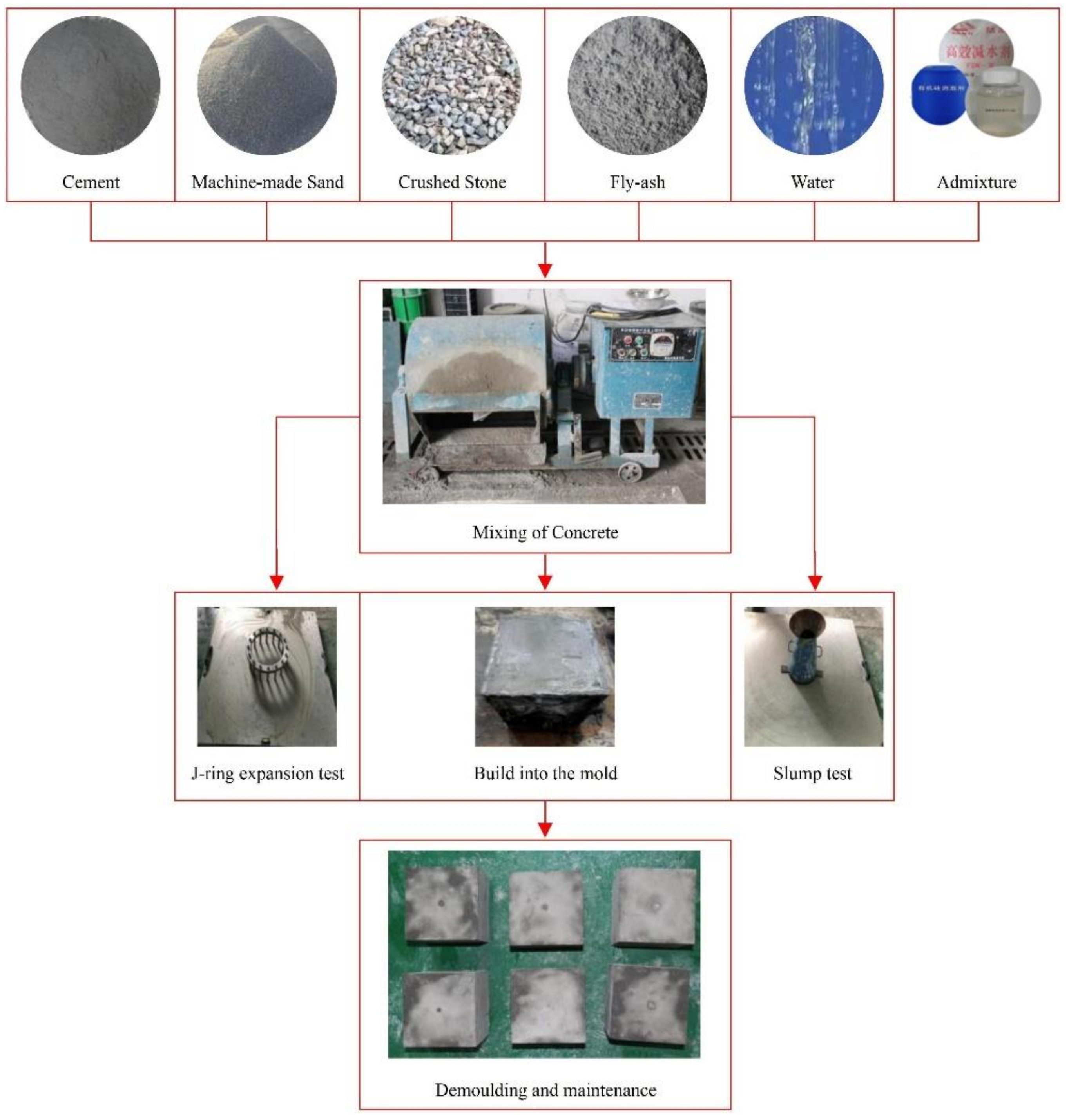
2. Sample Preparation
3. Factors Controlling Apparent Quality and Service Performance of SCFFC
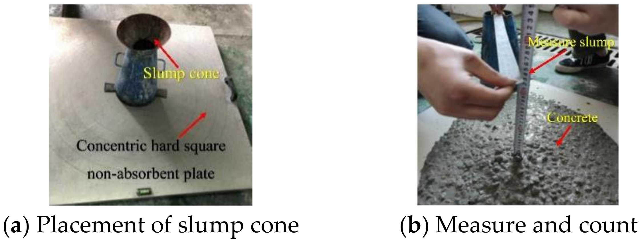
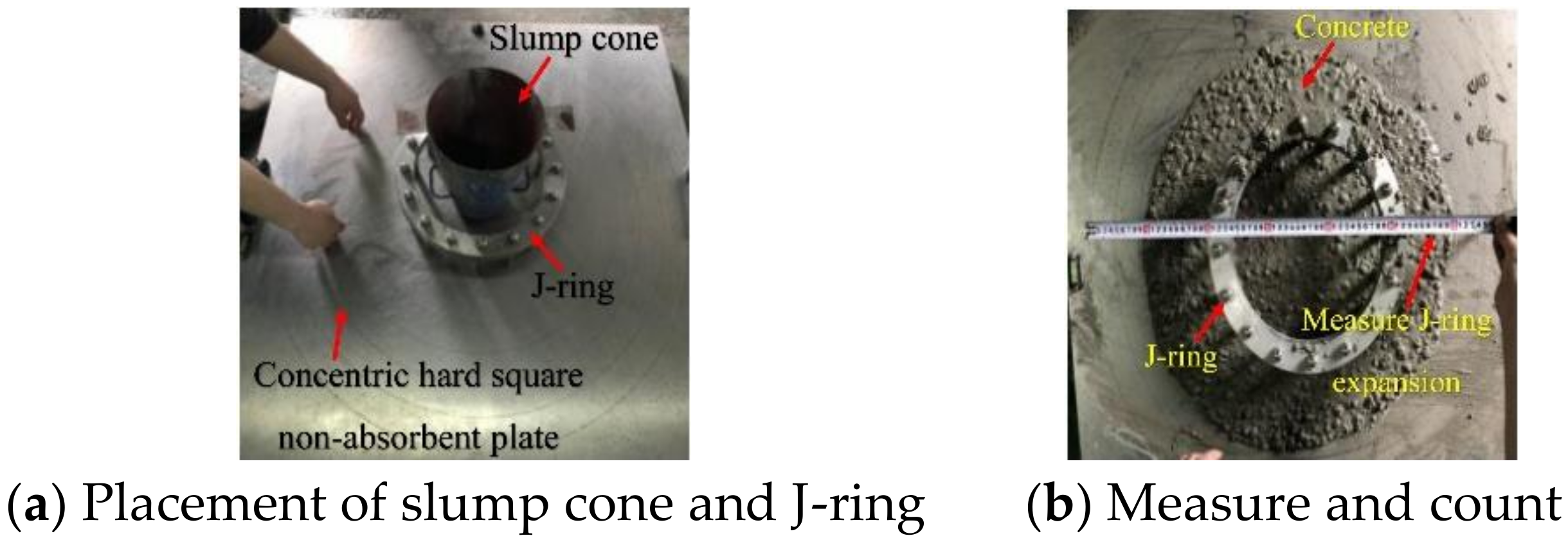
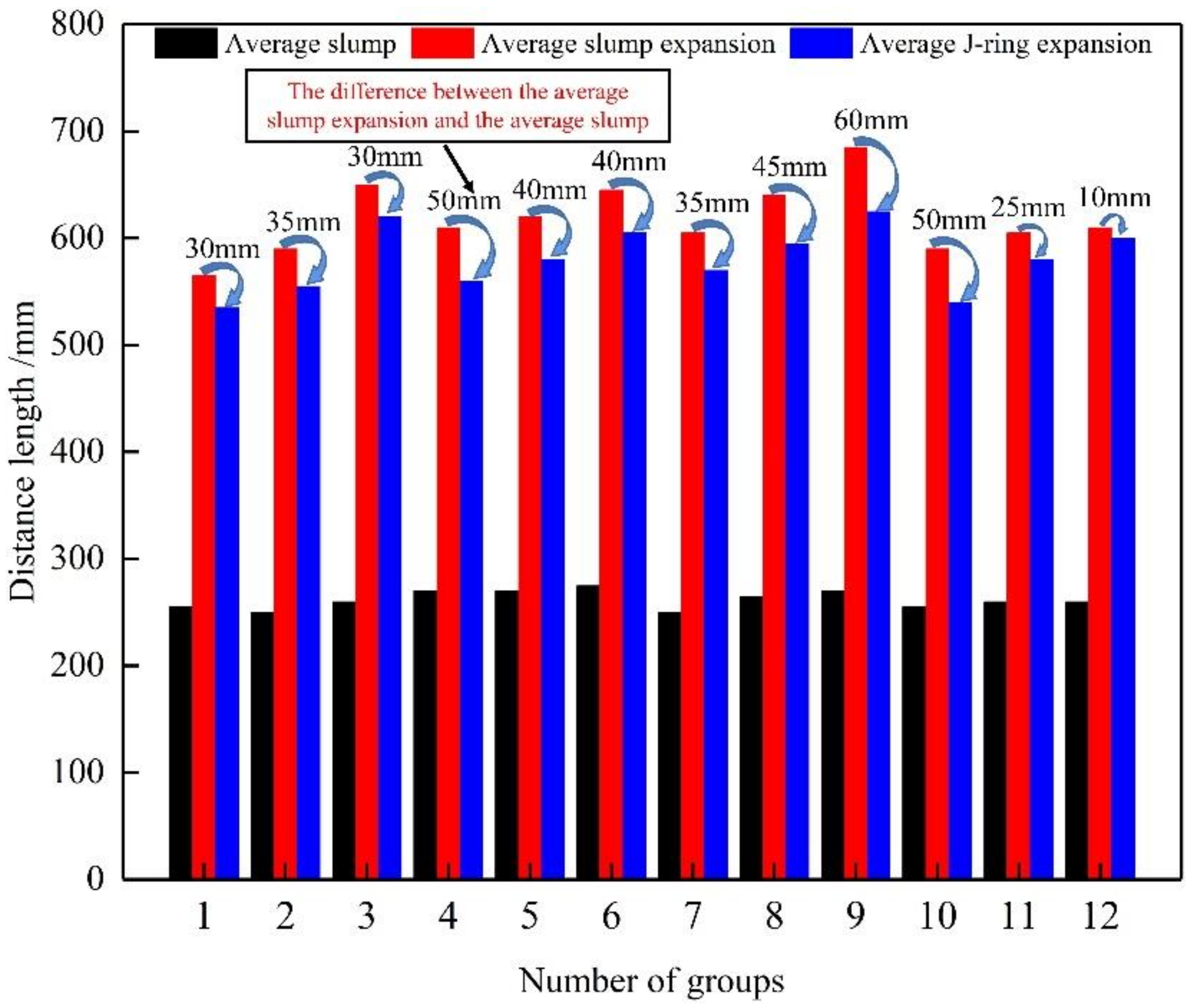
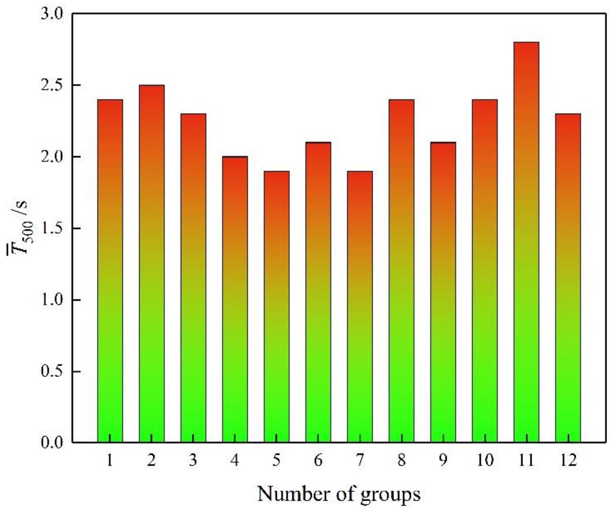
3.1. Statistics of Slump Expansion, Slump and J-Ring Expansion of SCFFC
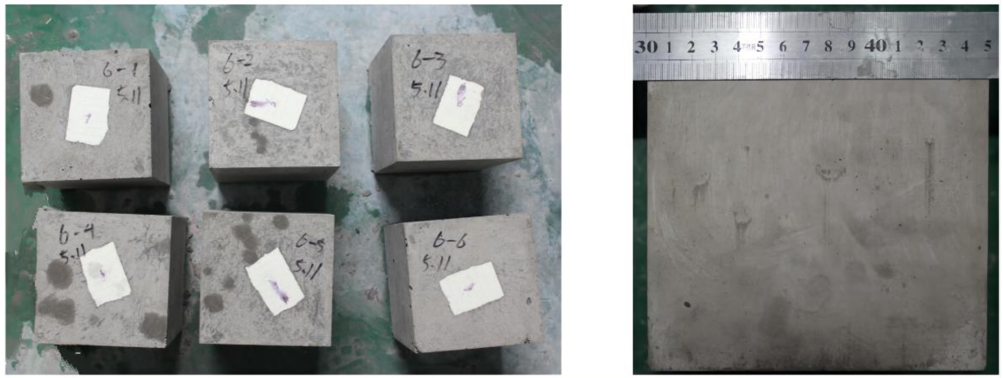
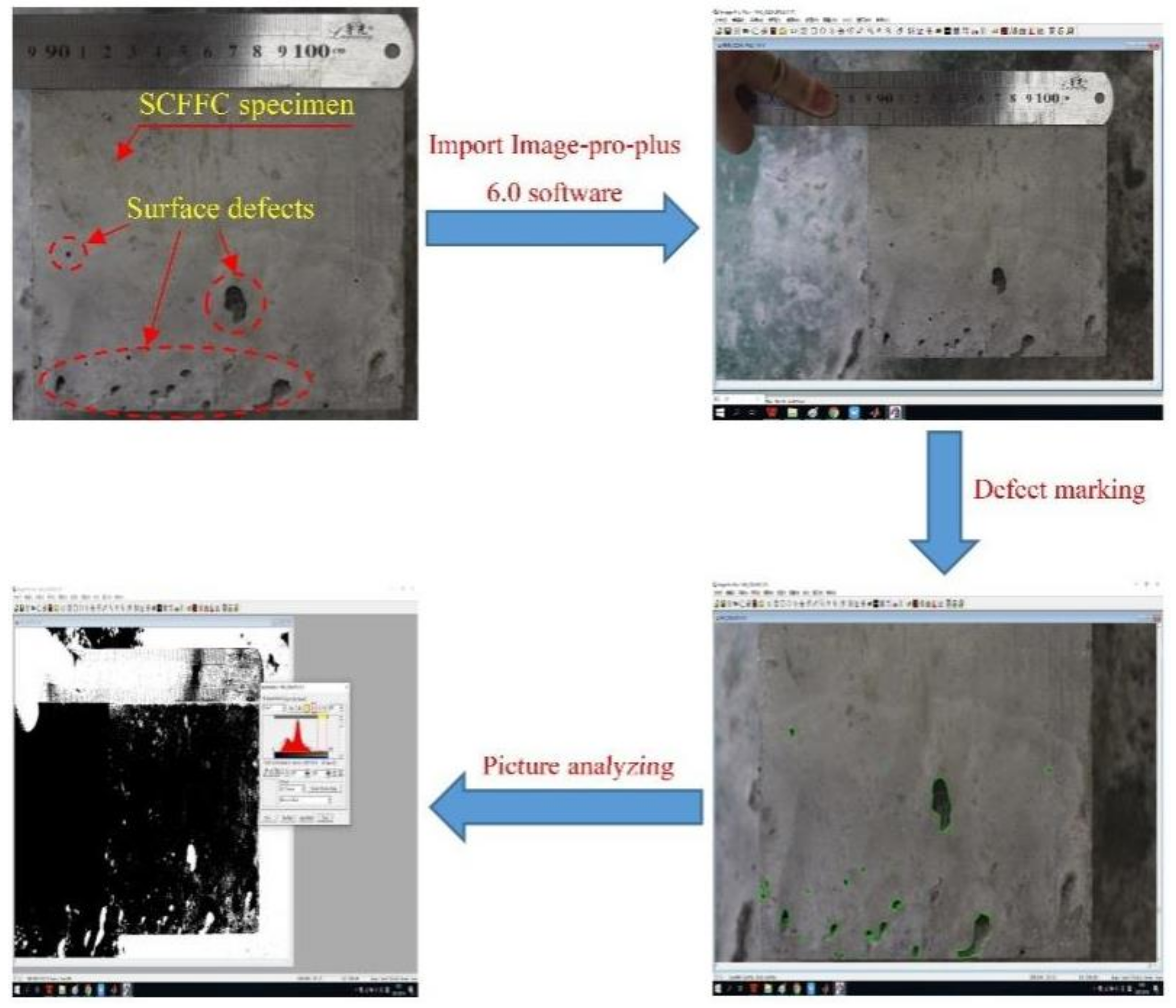
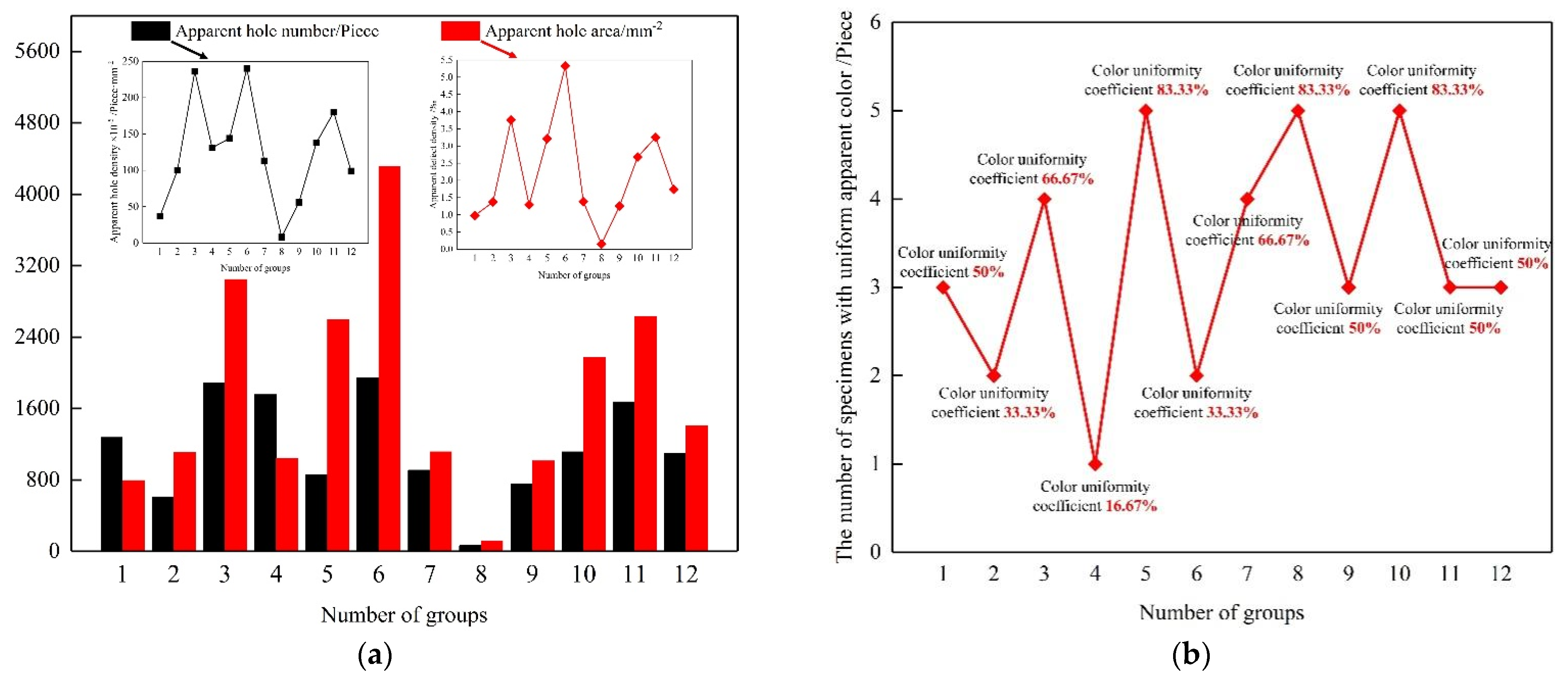
3.2. Statistics of Apparent Quality Parameters of SCFFC
4. Calculation of SCFFC Strength Index
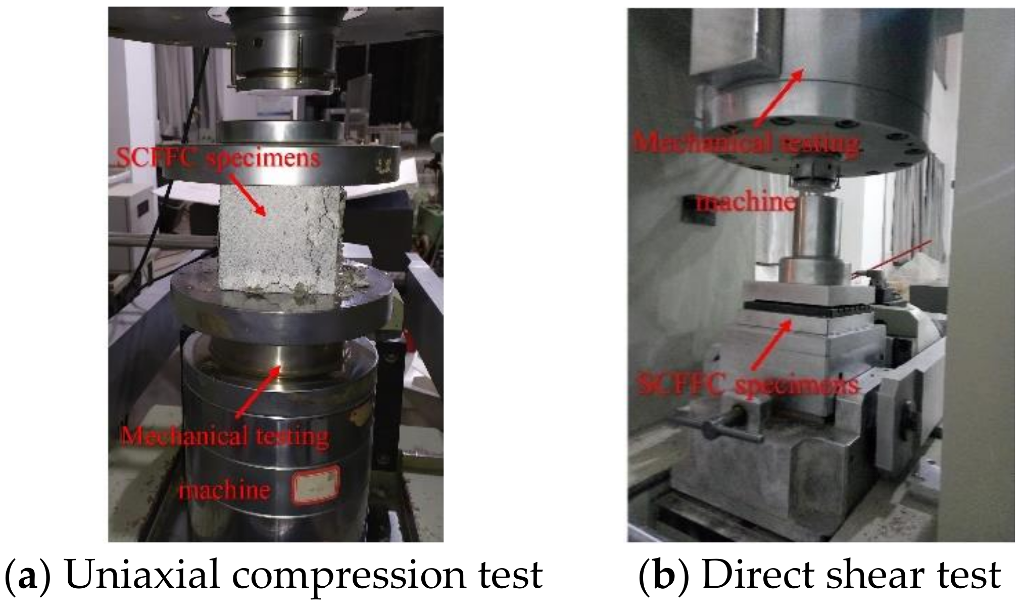
- (1)
- Selection of the concrete strength index: the uniaxial compressive strength and shear strength of concrete were taken as the evaluation indices of concrete strength, and these two strength values could be obtained by a uniaxial compression test and direct shear test of the concrete.
- (2)
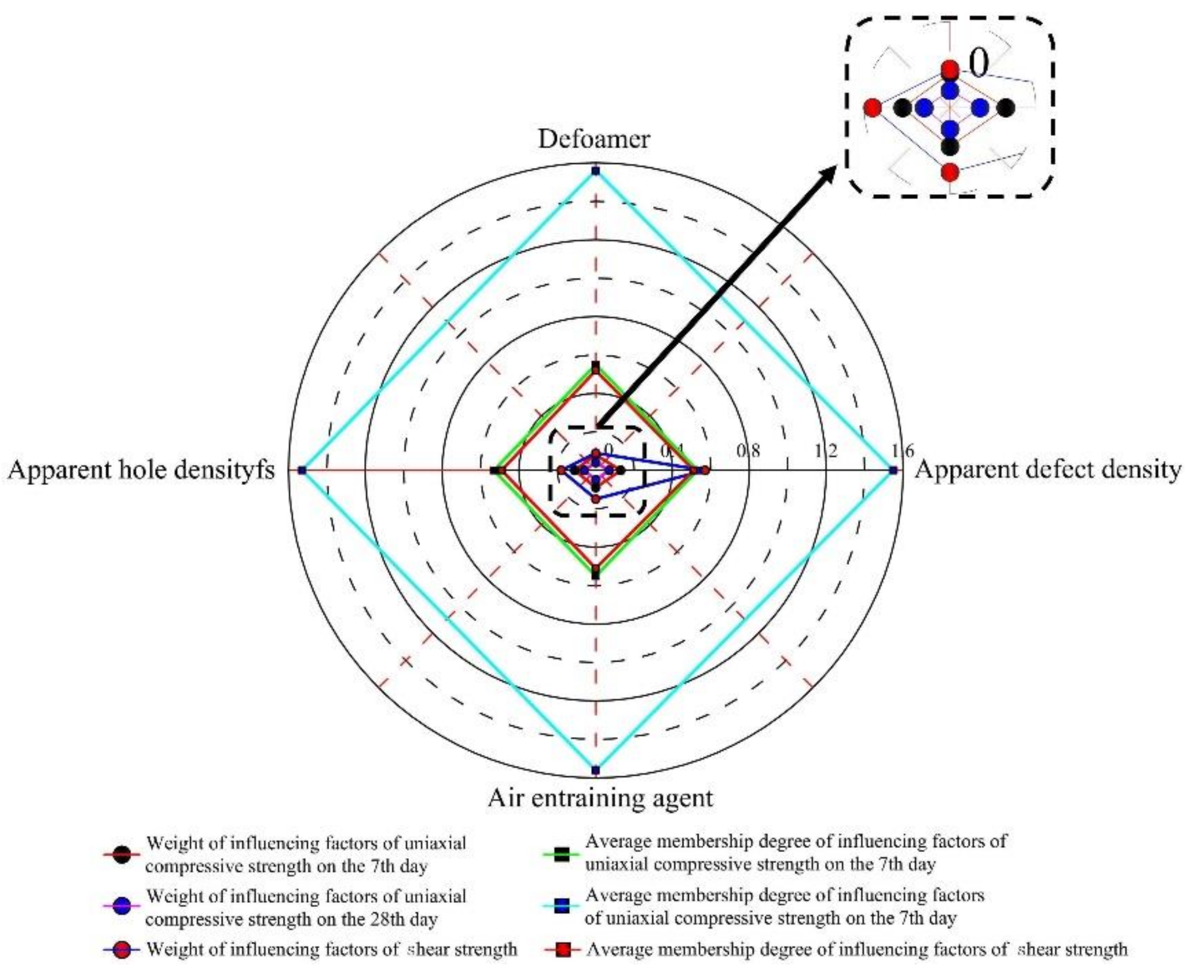
- Determination of the weight of each index: the authors analyzed the influences of various control factors on the strength indices of the concrete and determined the weight value of each index.
- (3)
- Establishment of the membership degree function and the calculation of the membership degree: the membership degree function was constructed to establish the mathematical expression between the concrete strength control factors and the strength indices. The ultimate goal was to convert the index values of different dimensions into dimensionless values between zero and one. The higher the degree of membership of a single index, the stronger its impact. The authors used the following formula to calculate the membership degrees of the uniaxial compressive strength and shear strength of the concrete.
4.1. Comprehensive Strength Verification and Significance Test of SCFFC
4.2. SCFFC Comprehensive Strength Evaluation
5. Conclusions
- (1)
- The combination of defoaming and air-entraining, by adding the defoamer and air-entraining agent according to different proportions for compound treatment, can solve the problems of uneven bubbles and poor bubble diameter in C30 SCFFC. It can simultaneously ensure that C30 SCFFC has sufficient water retention, fluidity, cohesion, passing quality through gaps, etc. The authors conducted experiments on SCFFC fabricated according to the mix ratio specified in this paper. After analyzing the data on slump expansion, slump, and J-ring expansion, this research concluded that the SCFFC’s first-class rate of filling-ability was 83.33%, and its first-class rate of passing quality through gaps was 75%. The test results show that the concrete fabricated according to the mix ratio given in this paper effectively reached the standard of high-class SCFFC.
- (2)
- When the amount of defoamer was constant, with an increase in air-entraining agent, the slump extension and J-ring expansion of the concrete gradually increased, the slump and expansion time fluctuated, and the fluctuation range was small. When the amount of air-entraining agent was constant, with an increase in defoamer, the slump extension, slump, and J-ring expansion of the concrete increased at first and then decreased, and the slump expansion time decreased at first and then increased. Considering this and the test data, this research concluded that when the defoamer dosage is 0.5‰ of that of the water reducer, and the dosage of air-entraining agent is 0.1‰ of that of cement, the workability and passing quality through gaps of concrete are the highest.
- (3)
- The effects of the addition of defoamer and air-entraining agent on the apparent hole number, apparent hole area, and color uniformity of the concrete fluctuated. This phenomenon lacked regularity, and this research could only find a better proportion from among many proportions. However, this result also reflected that the additions of defoamer and air-entraining agent influenced the quality of the concrete, and the additional amounts of both must be strictly controlled. When the defoamer dosage is 0.5‰ of that of the water reducer and the dosage of air-entraining agent is 0.1‰ of that of the cement, the apparent holes in the SCFFC are small, as were their area and quantity. The distribution and apparent color of the SCFFC are uniform.
- (4)
- This research found that the additional amounts of defoamer and air entraining agent, the apparent hole number and apparent defect density have remarkable effects on the strength of the concrete. Uniaxial compression tests and direct shear tests are conducted on concrete specimens with different mix ratios. This research also performed a comprehensive analysis of the weight, subjection degree, variability, stability, and strength index of the influencing factors based on fuzzy mathematics. This research found that the C30 SCFFC material with the highest apparent quality and service performance has the following ratio: Cement:Machine-made Sand:Crushed Stone:Fly-ash:Water = 4:8.6:9.3:1:2.2. The water reducer is 1.0% of the total mass of the cementitious materials. The defoamer dosage is 0.5‰ of that of the water reducer, and the dosage of the air-entraining agent is 0.1‰ of that of cement. The self-compacting fair-faced concrete prepared according to the above ratio meets the strength requirements and solves problems such as honeycomb and hemp surface in the filling process of secondary tunnel lining concrete.
Author Contributions
Funding
Institutional Review Board Statement
Informed Consent Statement
Data Availability Statement
Acknowledgments
Conflicts of Interest
References
- Rankoth, C.K.; Hosoda, A.; Iwama, K. Modeling and Verification of Early Age Thermal Stress in Second Lining Concrete of NATM Tunnels. J. Adv. Concr. Technol. 2017, 15, 213–226. [Google Scholar] [CrossRef] [Green Version]
- Wang, R.Y.; Yan, Q.Q.; Tian, B.; Xie, J.D. Effect of Moisture Content and Fiber on the High-Temperature Properties of Tunnel Second Lining Concrete. J. Highw. Transp. Res. Dev. 2015, 9, 63–68. [Google Scholar] [CrossRef]
- Lukic, D.C.; Zlatanovic, E.M.; Jokanovic, I.M. Tunnel lining load with consideration of the rheological properties of rock mass and concrete. Geomech. Eng. 2020, 21, 53–62. [Google Scholar] [CrossRef]
- Lu, C.C.; Hwang, J.H. Damage analysis of the new Sanyi railway tunnel in the 1999 Chi-Chi earthquake: Necessity of second lining reinforcement. Tunn. Undergr. Space Technol. 2018, 73, 48–59. [Google Scholar] [CrossRef]
- Fang, Y.; Guo, J.; Grasmick, J.; Mooney, M. The effect of external water pressure on the liner behavior of large cross-section tunnels. Tunn. Undergr. Space Technol. Inc. Trenchless Technol. Res. 2016, 60, 80–95. [Google Scholar] [CrossRef]
- Zhou, Y.; Su, K.; Wu, H. Hydro-mechanical interaction analysis of high pressure hydraulic tunnel. Tunn. Undergr. Space Technol. Inc. Trenchless Technol. Res. 2015, 47, 28–34. [Google Scholar] [CrossRef]
- Russo, N.; Gastaldi, M.; Marras, P.; Schiavi, L.; Strini, A.; Lollini, F. Effects of load-induced micro-cracks on chloride penetration resistance in different types of concrete. Mater. Struct. 2020, 53, 143. [Google Scholar] [CrossRef]
- Cuenca, E.; Rigamonti, S.; Gastaldo Brac, E.; Ferrara, L. Crystalline Admixture as Healing Promoter in Concrete Exposed to Chloride-Rich Environments: Experimental Study. J. Mater. Civ. Eng. 2021, 33, 040204911. [Google Scholar] [CrossRef]
- Zhang, Y.; Yuan, M.; Liu, C.; Zhang, X.; Yang, B.; Yang, J. Repairing Damaged Tunnel Lining with Small-Size Cavity in Surrounding Rocks. J. Perform. Constr. Facil. 2021, 35, 06021002. [Google Scholar] [CrossRef]
- Jayanth, K.; Prakash, M.N.; Suresh, G.S.; Naveen, B.O. Studies on the behaviour of steel fibre-reinforced concrete under monotonic and repeated cyclic stress in compression. Arch. Civ. Mech. Eng. 2022, 22, 50. [Google Scholar] [CrossRef]
- Wang, X.; Fan, F.; Lai, J.; Xie, Y. Steel fiber reinforced concrete: A review of its material properties and usage in tunnel lining. Structures 2021, 34, 1080–1098. [Google Scholar] [CrossRef]
- Abbas, S.; Nehdi, M.L. Mechanical Behavior of Ultrahigh-Performance Concrete Tunnel Lining Segments. Materials 2021, 14, 2378. [Google Scholar] [CrossRef] [PubMed]
- Solouki, A.; Tataranni, P.; Sangiorgi, C. Mixture Optimization of Concrete Paving Blocks Containing Waste Silt. Sustainability 2022, 14, 451. [Google Scholar] [CrossRef]
- An, D.; Chen, Z.; Cui, G. Research on Seismic Performance of Fiber Concrete Lining Structure of Urban Shallow-Buried Rectangular Tunnel in Strong Earthquake Area. KSCE J. Civ. Eng. 2021, 25, 2378. [Google Scholar] [CrossRef]
- Belyakov, N.; Smirnova, O.; Alekseev, A.; Tan, H. Numerical Simulation of the Mechanical Behavior of Fiber-Reinforced Cement Composites Subjected Dynamic Loading. Appl. Sci. 2021, 11, 1112. [Google Scholar] [CrossRef]
- Sheikh, K.A.; Saif, A. Steel Fibre-Reinforced Shotcrete as an alternative to conventional concrete tunnel lining: A case study of Gulpur Hydropower Project. Geomech. Geoengin. 2020, 15, 252–262. [Google Scholar] [CrossRef]
- Cugat, V.; Cavalaro, S.H.P.; Bairán, J.M.; de la Fuente, A. Safety format for the flexural design of tunnel fibre reinforced concrete precast segmental linings. Tunn. Undergr. Space Technol. Inc. Trenchless Technol. Res. 2020, 103, 103500. [Google Scholar] [CrossRef]
- Xu, Z.; Wu, J.; Zhao, M.; Bai, Z.; Wang, K.; Miao, J.; Tan, Z. Mechanical and microscopic properties of fiber-reinforced coal gangue-based geopolymer concrete. Nanotechnol. Rev. 2022, 11, 526–543. [Google Scholar] [CrossRef]
- Wang, X.; Liu, L.; Fu, R.; Sun, X. Newly developed pressure adaptable concrete lining for high pressure hydraulic tunnels. Tunn. Undergr. Space Technol. Inc. Trenchless Technol. Res. 2020, 105, 103570. [Google Scholar] [CrossRef]
- Xin, C.L.; Wang, Z.Z.; Zhou, J.M.; Gao, B. Shaking table tests on seismic behavior of polypropylene fiber reinforced concrete tunnel lining. Tunn. Undergr. Space Technol. Inc. Trenchless Technol. Res. 2019, 88, 1–15. [Google Scholar] [CrossRef]
- Alaloul, W.S.; Musarat, M.A.; Haruna, S.; Law, K.; Tayeh, B.A.; Rafiq, W.; Ayub, S. Mechanical Properties of Silica Fume Modified High-Volume Fly Ash Rubberized Self-Compacting Concrete. Sustainability 2021, 13, 5571. [Google Scholar] [CrossRef]
- Magbool, H.M.; Zeyad, A.M. The effect of varied types of steel fibers on the performance of self-compacting concrete modified with volcanic pumice powder. Mater. Sci.-Pol. 2021, 39, 172–187. [Google Scholar] [CrossRef]
- Hilal, N.; Al Saffar, D.M.; Ali, T.K.M. Effect of egg shell ash and strap plastic waste on properties of high strength sustainable self-compacting concrete. Arab. J. Geosci. 2021, 14, 291. [Google Scholar] [CrossRef]
- Kumar, B.N.; Abhilash, B.; Naveen Kumar, C.H.; Pavan, S. Effect of Nano Materials on Performance Characteristics of High Strength Self Compacting Concrete. Assian Res. Assoc. 2021, 2, 26–35. [Google Scholar] [CrossRef]
- Honglei, C.; Zuquan, J.; Penggang, W.; Jianhong, W.; Jian, L. Comprehensive resistance of fair-faced concrete suffering from sulfate attack under marine environments. Constr. Build. Mater. 2021, 277, 122312. [Google Scholar] [CrossRef]
- Zhang, H.; Zhang, J.; Yang, Y.; Hu, Q.; He, Y.; Wei, P. Effects of asphalt emulsion on the durability of self-compacting concrete. Constr. Build. Mater. 2021, 292, 123322. [Google Scholar] [CrossRef]
- Grinys, A.; Balamurugan, M.; Augonis, A.; Ivanauskas, E. Mechanical Properties and Durability of Rubberized and Glass Powder Modified Rubberized Concrete for Whitetopping Structures. Materials 2021, 14, 2321. [Google Scholar] [CrossRef]
- Gnanaraj, S.C.; Chokkalingam, R.B.; Thankam, G.L.; Pothinathan, S.K.M. Influence of Steatite and Fly Ash on the Fresh-Hardened Properties and Micromorphology of Self-Compacting Concrete. Adv. Mater. Sci. Eng. 2021, 2021, 6627450. [Google Scholar] [CrossRef]
- Belebchouche, C.; Moussaceb, K.; Bensebti, S.E.; Aït-Mokhtar, A.; Hammoudi, A.; Czarnecki, S. Mechanical and Microstructural Properties of Ordinary Concrete with High Additions of Crushed Glass. Materials 2021, 14, 1872. [Google Scholar] [CrossRef]
- Khoshkbijari, R.K.; Samimi, M.F.; Mohammadi, F.; Talebitaher, P. Effects of Mica and Feldspar as partial cement replacement on the rheological, mechanical and thermal durability of self-compacting mortars. Constr. Build. Mater. 2020, 263, 120149. [Google Scholar] [CrossRef]
- Yang, X.C.; Ye, H.C.; Li, D.M.; Yu, X.C.; Liu, K.L.; Hu, Q.P.; Hu, Z.H.; Gu, Z.H.; Hu, H.W.; Zhou, L.J.; et al. Assessment of red soil upland fertility in long-term fertilization based on fuzzy mathematics and principal component analysis. Soil Fertil. Sci. China 2018, 3, 79–84. (In China) [Google Scholar] [CrossRef]
- Terenchuk, S.; Yeremenko, B.; Kartavykh, S.; Nasikovskyi, O. Application of fuzzy mathematics methods to processing geometric parameters of degradation of building structures. EUREKA Phys. Eng. 2018, 1, 56–62. [Google Scholar] [CrossRef]
- Kuzyakov, O.N.; Kolosova, A.L.; Andreeva, M.A. System for corrosion monitoring in pipeline applying fuzzy logic mathematics. J. Phys. Conf. Ser. 2018, 1015, 052017. [Google Scholar] [CrossRef]


| Density /g∙cm−3 | Specific Surface Area /m2∙kg−1 | Water Requirement of Normal Consistency /% | Setting Time min | Le Chatelier Soundness Test /mm | Mortar Strength /MPa | ||||
|---|---|---|---|---|---|---|---|---|---|
| Initial Setting Time/s | Final Setting Time/s | 3D Flexural Strength | 28D Flexural Strength | 3D Compressive Strength | 28D Compressive Strength | ||||
| 3.09 | 340 | 26.7 | 229 | 298 | 2.0 | 5.7 | 7.8 | 23.6 | 42.8 |
| Fly-Ash Grade | Fineness/% | Ignition Loss/% | Water Content/% | Water Demand Ratio/% |
|---|---|---|---|---|
| II | 23.5 | 5.2 | 0.2 | 84 |
| Number of Groups | Cement /kg∙m−3 | Machine-Made Sand /kg∙m−³ | Crushed Stone /kg∙m−³ | Fly-Ash /kg∙m−³ | Water /kg∙m−³ | Water Reducer /% | Water-Binder Ratio | Density /kg∙m−³ | Defoamer /‰ | Air Entraining Agent/‰ |
|---|---|---|---|---|---|---|---|---|---|---|
| Group 1 | 372.94 | 801.86 | 867.20 | 93.23 | 204.31 | 1.00 | 0.44 | 2800 | 0.1 | 0.05 |
| Group 2 | 0.10 | |||||||||
| Group 3 | 0.15 | |||||||||
| Group 4 | 0.3 | 0.05 | ||||||||
| Group 5 | 0.10 | |||||||||
| Group 6 | 0.15 | |||||||||
| Group 7 | 0.5 | 0.05 | ||||||||
| Group 8 | 0.10 | |||||||||
| Group 9 | 0.15 | |||||||||
| Group 10 | 0.7 | 0.05 | ||||||||
| Group 11 | 0.10 | |||||||||
| Group 12 | 0.15 |
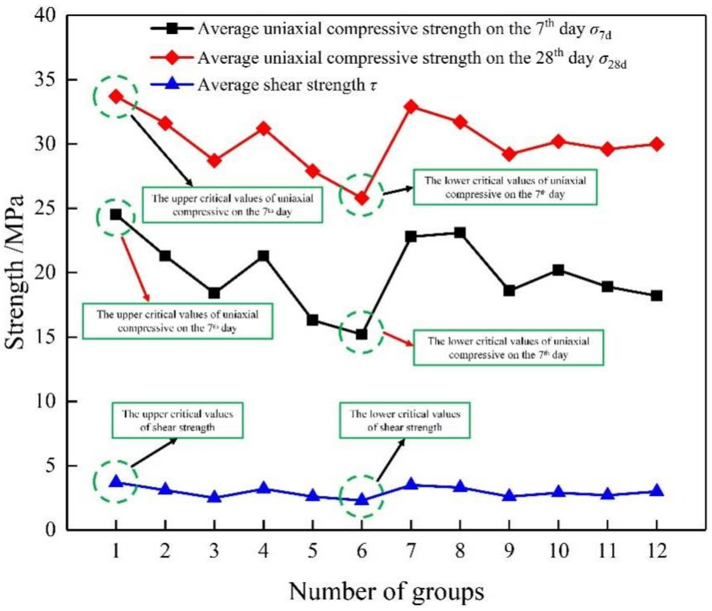
| SCFFC Strength Index | Lower Critical Values X1/MPa | Upper Critical Values X2/MPa |
|---|---|---|
| Uniaxial compressive strength on the 7th day | 15.2 | 24.5 |
| Uniaxial compressive strength on the 28th day | 25.8 | 33.7 |
| Shear strength | 2.3 | 3.7 |
| Influencing Factors | Uniaxial Compressive Strength on the 7th Day/MPa | Uniaxial Compressive Strength on the 28th Day/MPa | Shear Strength/MPa | |
|---|---|---|---|---|
| Defoamer/‰ | 0.1 | 21.4a | 31.3a | 3.1a |
| 0.3 | 17.6c | 28.3c | 2.7b | |
| 0.5 | 21.5a | 31.3a | 3.1a | |
| 0.7 | 19.1b | 29.9b | 2.9b | |
| Air entraining agent/‰ | 0.05 | 22.2a | 32.0a | 3.3a |
| 0.1 | 19.9b | 30.2b | 2.9b | |
| 0.15 | 17.6c | 28.4c | 2.6c | |
| Apparent hole density/Piece·mm−2 | 0–0.001 | 21.0b | 30.8b | 3.0b |
| 0.001–0.0015 | 19.4c | 30.3b | 3.0b | |
| 0.0015–0.002 | 24.5a | 33.7a | 3.7a | |
| 0.002–0.0025 | 18.5d | 28.8c | 2.7a | |
| Apparent defect density/‰ | 0–1.5 | 21.9a | 31.7a | 3.2a |
| 1.5–3.0 | 19.2b | 30.1b | 3.0b | |
| 3.0–4.5 | 17.9c | 28.7c | 2.6c | |
| 4.5–6.0 | 15.2d | 25.8d | 2.3d | |
| Influencing Factors | Uniaxial Compressive Strength | |||||||||
|---|---|---|---|---|---|---|---|---|---|---|
| 7d | 28d | 7d | 28d | 7d | 28d | 7d | 28d | 7d | 28d | |
| ∆σ /MPa | CVσ | Wσ | ||||||||
| Defoamer | 19.9 | 30.2 | 1.64 | 1.24 | 0.08 | 0.04 | 0.08 | 0.04 | 0.55 | 1.56 |
| Air entraining agent | 19.9 | 30.2 | 1.88 | 1.47 | 0.09 | 0.05 | 0.09 | 0.05 | 0.55 | 1.56 |
| Apparent hole density | 20.9 | 30.9 | 2.29 | 1.78 | 0.11 | 0.06 | 0.11 | 0.06 | 0.53 | 1.53 |
| Apparent defect density | 18.6 | 29.1 | 2.41 | 2.17 | 0.13 | 0.07 | 0.13 | 0.07 | 0.53 | 1.55 |
| Influencing Factors | Shear Strength | ||||
|---|---|---|---|---|---|
| ∆τ/MPa | CVτ | Wτ | |||
| Defoamer | 3.0 | 0.17 | 0.06 | 0.09 | 0.52 |
| Air entraining agent | 2.9 | 0.29 | 0.10 | 0.15 | 0.51 |
| Apparent hole density | 3.1 | 0.37 | 0.12 | 0.18 | 0.49 |
| Apparent defect density | 2.8 | 1.04 | 0.37 | 0.57 | 0.51 |
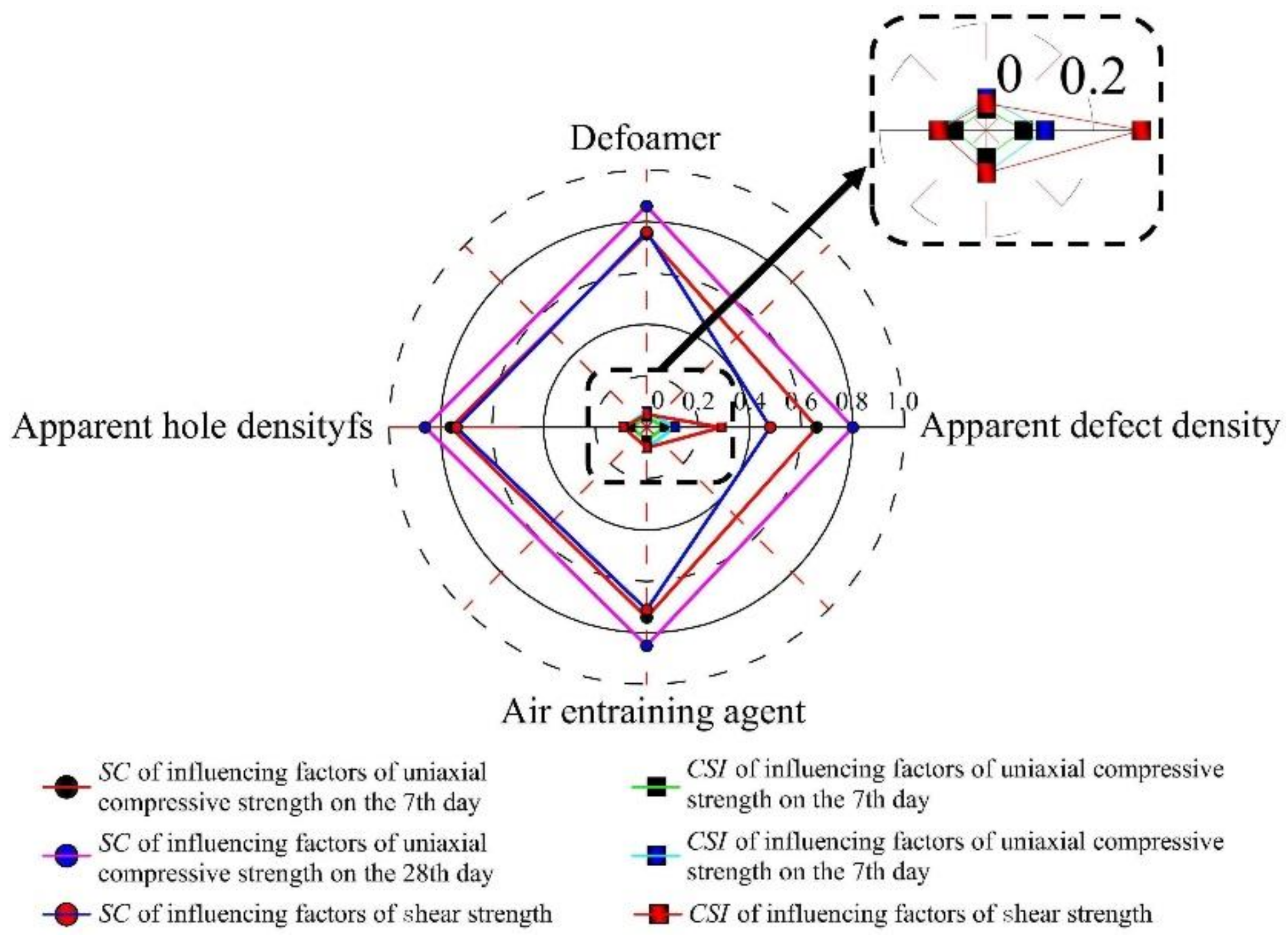
| Influencing Factors | Uniaxial Compressive Strength | Shear Strength | ||||
|---|---|---|---|---|---|---|
| 7D | 28D | 7D | 28D | |||
| SC | CSI | SC | CSI | |||
| Defoamer | 0.75 | 0.86 | 0.04 | 0.06 | 0.76 | 0.05 |
| Air entraining agent | 0.74 | 0.85 | 0.05 | 0.08 | 0.71 | 0.08 |
| Apparent hole density | 0.76 | 0.86 | 0.06 | 0.09 | 0.74 | 0.09 |
| Apparent defect density | 0.66 | 0.80 | 0.07 | 0.11 | 0.48 | 0.29 |
| Influencing Factors | Uniaxial Compression Strength | |||||||||||
|---|---|---|---|---|---|---|---|---|---|---|---|---|
| CV | SC | CSI | ||||||||||
| 7D | 28D | 7D | 28D | 7D | 28D | |||||||
| Result | Rank | Result | Rank | Result | Rank | Result | Rank | Result | Rank | Result | Rank | |
| Defoamer | 0.08 | 4 | 0.04 | 4 | 0.75 | 2 | 0.86 | 1 | 0.04 | 4 | 0.06 | 4 |
| Air entraining agent | 0.09 | 3 | 0.05 | 3 | 0.74 | 3 | 0.85 | 2 | 0.05 | 3 | 0.08 | 3 |
| Apparent hole density | 0.11 | 2 | 0.06 | 2 | 0.76 | 1 | 0.86 | 1 | 0.06 | 2 | 0.09 | 2 |
| Apparent defect density | 0.13 | 1 | 0.07 | 1 | 0.66 | 4 | 0.80 | 3 | 0.07 | 1 | 0.11 | 1 |
| Influencing Factors | Shear Strength | |||||
|---|---|---|---|---|---|---|
| CV | SC | CSI | ||||
| Result | Rank | Result | Rank | Result | Rank | |
| Defoamer | 0.06 | 4 | 0.76 | 1 | 0.05 | 4 |
| Air entraining agent | 0.10 | 3 | 0.71 | 3 | 0.08 | 3 |
| Apparent hole density | 0.12 | 2 | 0.74 | 2 | 0.09 | 2 |
| Apparent defect density | 0.37 | 1 | 0.48 | 4 | 0.29 | 1 |
Publisher’s Note: MDPI stays neutral with regard to jurisdictional claims in published maps and institutional affiliations. |
© 2022 by the authors. Licensee MDPI, Basel, Switzerland. This article is an open access article distributed under the terms and conditions of the Creative Commons Attribution (CC BY) license (https://creativecommons.org/licenses/by/4.0/).
Share and Cite
Xie, C.; Tao, T.; Huang, K. Apparent Quality and Service Performance Evaluation of SCFFC in Tunnel Secondary Lining. Buildings 2022, 12, 479. https://doi.org/10.3390/buildings12040479
Xie C, Tao T, Huang K. Apparent Quality and Service Performance Evaluation of SCFFC in Tunnel Secondary Lining. Buildings. 2022; 12(4):479. https://doi.org/10.3390/buildings12040479
Chicago/Turabian StyleXie, Caijin, Tiejun Tao, and Keyu Huang. 2022. "Apparent Quality and Service Performance Evaluation of SCFFC in Tunnel Secondary Lining" Buildings 12, no. 4: 479. https://doi.org/10.3390/buildings12040479