1. Introduction
As stated by the master architect Gropius in 1910, ‘reinforced concrete buildings shall be prefabrication and factory’; architectural industrialization has been widely explored by researchers. Currently, the precast structure, the centerpiece of building industrialization, has the advantages of less wet work, better energy conservation, and faster construction than the conventional reinforced concrete structure [
1,
2,
3]. It has been widely used, including in the Osaka Kitahama Apartment Building in Japan, the Chunli River Apartment Building in China, and Phoenix Library in the United States. However, according to numerous investigations of strong earthquakes worldwide, the core area of the beam-column joint of the precast structure can be severely damaged in the event of a disaster. The damage results in the collapse of buildings, endangering people’s lives and property. The shortage of antiseismic, precast structures limits the development of industrialized construction [
4,
5,
6,
7,
8]. Numerous experimental investigations [
9,
10,
11,
12,
13] have revealed that the connection design of each precast component plays a key role in the seismic and mechanical performance of precast structure buildings. Accordingly, the connection parts should have sufficient stiffness, energy dissipation capacity, and ductility to ensure the transmission of the bending moment, shear force, and axial force between components [
14,
15,
16,
17,
18]. Therefore, enhancing the mechanical properties of fabricated structures by changing the connection mode of precast components has become the focus of research in recent years.
Many types of precast concrete beam-column joints currently exist. Three examples include the following: (1) In slot-bond assembled concrete joints, the precast concrete components are spliced by way of sunk key and steel anchoring, and the concrete is poured at the connection. This type of precast joint has good energy dissipation capacity and ductility, but wet operations on construction sites are a common issue [
19,
20,
21]. (2) In prestressed precast concrete joints, concrete members are connected with prestressed reinforcement. Many studies have found that, although this form of member connection has self-recovery ability and slow stiffness degradation, the prestressed reinforcement should be stretched during member assembly, making the construction complex [
22,
23,
24]. (3) Bolted or welded precast concrete joints refer to the pre-embedding of steel members in the joint area. The concrete beams and columns are combined by bolting or welding connections between the steel components. Although this type of connection mode improves the construction efficiency, the joint performance is not significantly improved, compared to when using the cast-in-suit concrete structure [
25,
26,
27]. The engineering applications of the above-mentioned precast joints are restricted, owing to the influence of factors, such as the post-pouring of concrete and the use of a complex joint structure [
8,
14,
17,
20,
23,
24,
25,
26,
27]. Therefore, it is of practical significance to develop an assembly system with superior constructability and performance.
In this study, a new type of precast beam-column joint is proposed [
28]. The joint has a simple steel connection mode, and steel members are only embedded in the connection of precast reinforced concrete members of the beam-column. During site construction, the members are assembled by a combination of bolting and welding methods. Buildings that rely on this form are called precast concrete structures with steel joints.
The connection form of the joints is the main factor affecting the production and assembly process of the prefabricated components. The load of the precast structure quickly rises during the construction process, then the overall stiffness, load, and stress of the structure are constantly changing. Taken together, it is highly significant to ensure safety during construction. Previous studies [
29,
30,
31,
32,
33,
34] in structural health monitoring are mostly focused on complex component design, construction monitoring, and monitoring systems, and they provide a volume of monitoring technologies [
35]. However, this enormous effort has yielded only a small amount of construction monitoring and simulation research for the precast concrete structure; it is an ongoing research issue.
Construction monitoring is performed by means of monitoring and numerical simulation [
35]. The former arranges monitoring devices on the construction site to carry out real-time monitoring of the structure status, so as to discover the construction risk in time; The latter pre-analyzes the state of the building structure during the construction process by means of numerical simulation and verifies the simulation results with the monitoring data of the construction site, thereby preventing the construction risk in advance. Due to the lack of theoretical verification, the accuracy of on-site monitoring data cannot be guaranteed, and real-time monitoring repair of the damaged part may require great effort. In response to some of the above shortcomings, this study applied both numerical simulation and structural health monitoring methods to discuss the whole process of construction, structural deformation, and stress monitoring and evaluation, so as to optimize the construction scheme and ensure the safety and orderly nature of construction.
This article intends to introduce this novel steel-joint precast concrete frame structure; analyze engineering examples of this type of structural system; and describe the advantages, component design, component production, and construction process. Meanwhile, a reasonable construction technology of steel-joint precast concrete structure and a scientific construction monitoring technology are proposed to guarantee the safety of the new system in the construction stage. Then, we will compare the conventional reinforced concrete structure and the precast concrete structure in terms of construction efficiency and building energy consumption. This research can provide a reference for future research on precast buildings and the application of the structural system itself.
2. Steel-Joint Precast Concrete Structure System
2.1. Advantages of Steel-Joint Precast Concrete Structure System
Precast concrete structures are usually connected by grouting sleeves and steel bar binding at the connection of the precast members. Moreover, the whole structure is formed by pouring concrete at the joint. This type of structural system requires additional process links, such as formwork, binding steel bar, concrete pouring, and maintenance, when assembling precast members, which significantly occupies both construction time and labor. Meanwhile, the concealment of the joint area in the concrete is not conducive to checking the connection quality of the members and the reinforcement and repair of the defects at the joint in the later stage.
The proposed structure improves upon the shortcomings of the precast concrete members’ connectors. The main design purpose of the new joint is to use the steel structure connection technology to solve the difficult assembly problem of the conventional connection mode of the concrete precast members. However, the joint needs to be used in conjunction with the structure system. If the other selected components do not match the joint, the advantages of the joint or system cannot be utilized, and even the joint or system cannot be truly put into application. Therefore, this study designs a steel-joint precast concrete structure system based on the steel connection method.
The prefabricated steel-joint connection [
28] refers to the reinforced concrete structure in which the precast beams and columns are embedded with steel components at the connection points, and the beam-column connection points are joined by the steel structure connection mode. The main purpose of the joint connection design is to solve the related problems of the difficult connection of the precast concrete structure with the steel structure connection mode. The precast beam in this project is embedded with H-shaped steel at the beam end, and the precast column connection node is embedded with a square steel pipe. The upper and lower horizontal plates, cross-type dividers, and extending connecting plates are built into the square steel pipe. The beam-column connection node is mainly connected by a combination of high-strength bolts and welds.
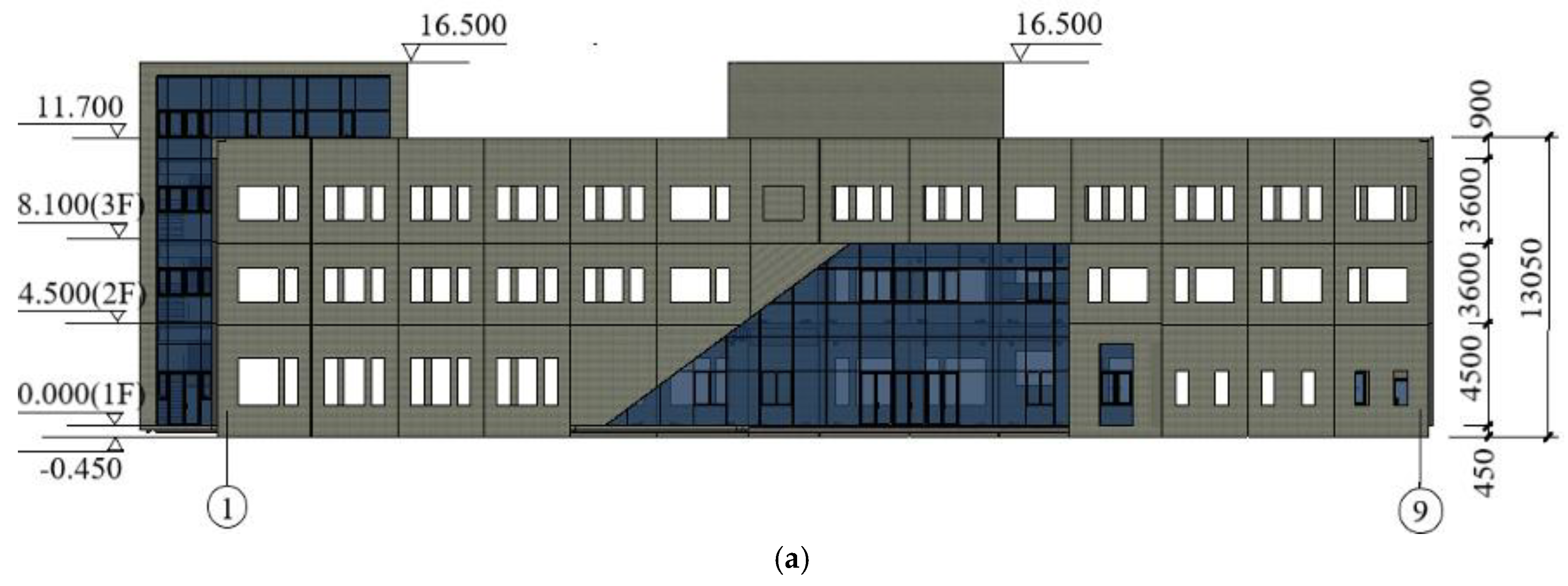
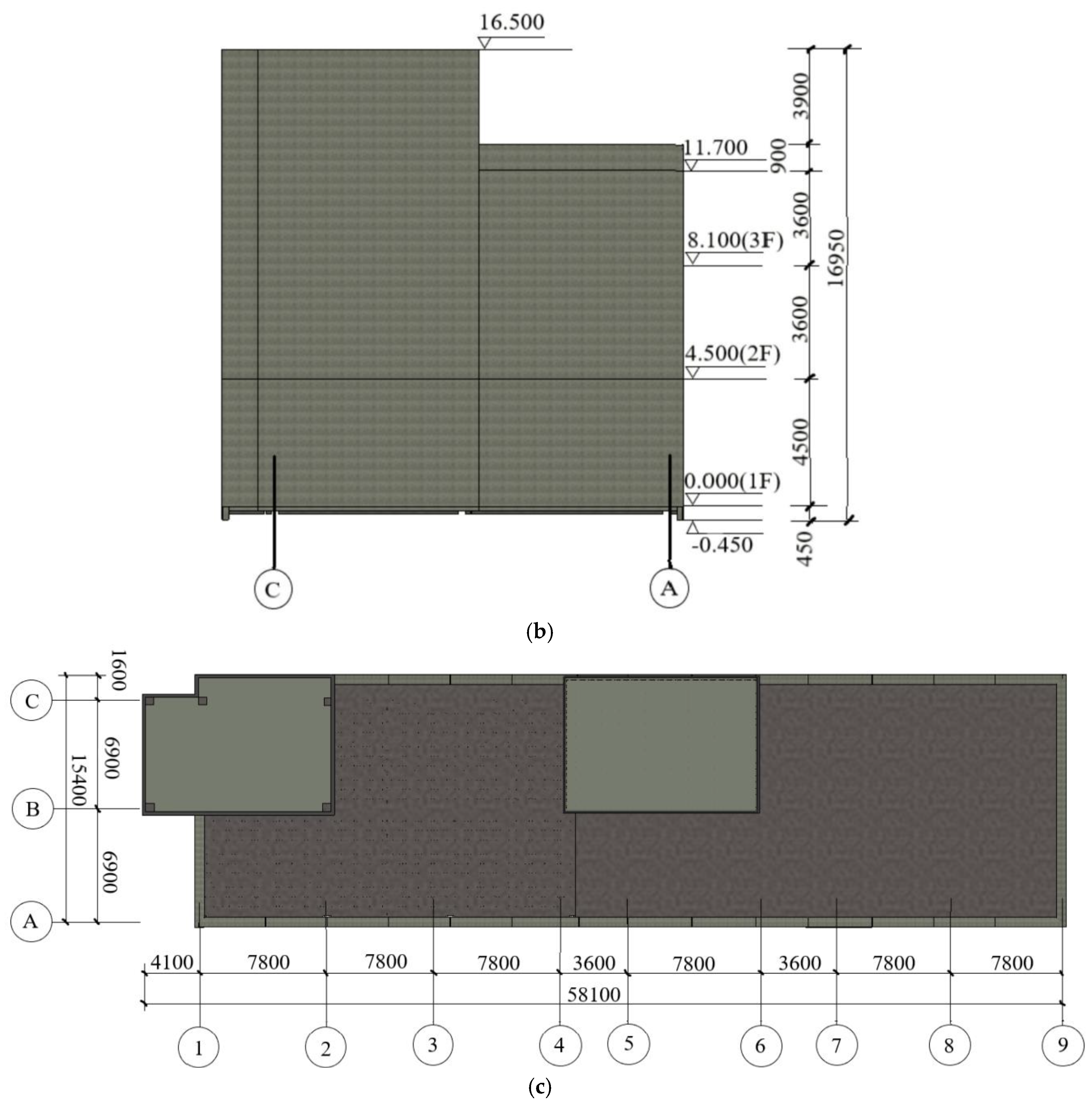
The novel structural system is applied to a precast office building in Lingshou Town, Shijiazhuang, Hebei Province, China. The building scene is shown in
Figure 1.
The project is a four-story frame structure building, which is partially three-story. The building area is 2821.2 m2, the structure height is 16.5 m, and the building height from one to four layers are 4.5 m, 3.6 m, 3.6 m, and 4.8 m, respectively. The first floor is used as an exhibition hall, and the other floors are used as offices and meeting rooms. The building is divided into two structural monomers. The structural monomer from axis 1 to axis 4 is a steel-joint prefabricated concrete frame structure made of precast columns, precast beams, composite slabs, and precast stairs. The structural monomer from axis 5 to axis 9 is the casting reinforced concrete frame structure. The construction stage of axis 1~4 starts after the completion of the construction stage of axis 5~9, and the two construction stages do not affect each other.
The project building has the characteristics of low height and fewer layers, and the prefabricated columns are all non-spliced full-length prefabricated components with a cross-sectional area of 0.5 m × 0.5 m. The steel component material is Q345, the steel reinforcement strength grade used in the building is mainly HRB400, and the concrete strength grade used in the precast component and the concrete pouring of the building floor is C30. The volume, weight, and quantity of each precast component are shown in
Table 1.
This structural system is popular and practical for project construction. The construction of precast concrete structures with steel joints is shown in
Figure 2. From the perspective of engineering applicability, the precast components connected by the steel structure are mature and reliable, which results in low requirements at the installation and management level of the construction personnel. From the perspective of engineering economy, the dry connection of precast components is fast and convenient, and concrete should not be poured after the connection of members. Therefore, the demand for manpower, construction time, and building materials is low in engineering construction. In addition, unlike when using integral steel components for steel structures, the project cost is reduced. From the perspective of engineering durability, the precast members are mainly reinforced concrete materials with excellent corrosion resistance and fire resistance. In summary, the precast concrete structure with steel joints is a form of building structure system that combines the merits of steel structure and reinforced concrete structure.
2.2. Design and Production of Precast Components
Reasonable modular design is an indispensable factor in determining whether the precast structure system building can be popularized. The modular design can realize the batch production of precast components and production with less specification, which can reduce the amortization cost of molds and reduce the engineering cost. The modular design is conducted in accordance with the requirements of building function, bearing capacity, number of building floors, building elevation, etc. For example, the number of steel-embedded parts of precast column members is selected according to the number of building floors. In addition, the beam span length is selected according to the building-use function. Moreover, steel members are buried in precast beams according to the location of the filling wall in the building to erect secondary beams, and so on. In addition, the precast concrete structure with steel joints can be applied to a variety of building types through a reasonable modular design, which can meet the different functions of the building and improve the engineering economy.
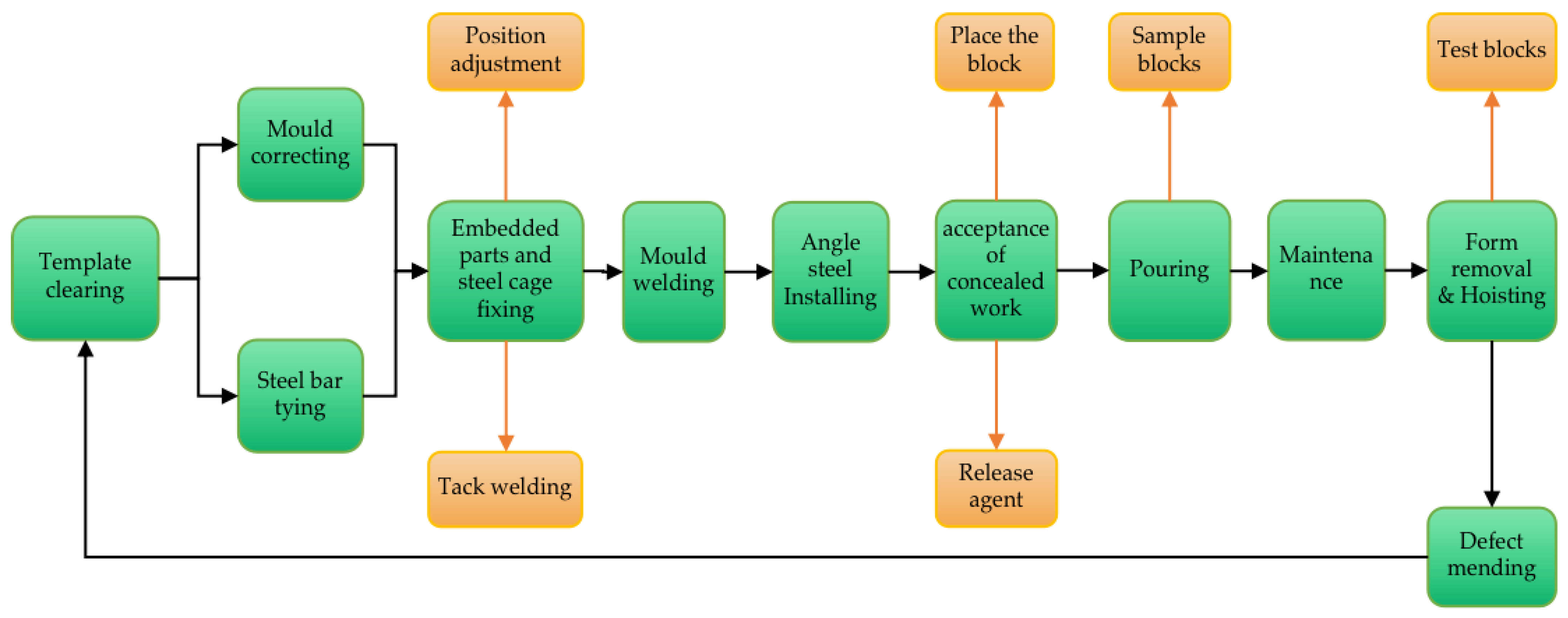
The production process of precast components is shown in
Figure 3.
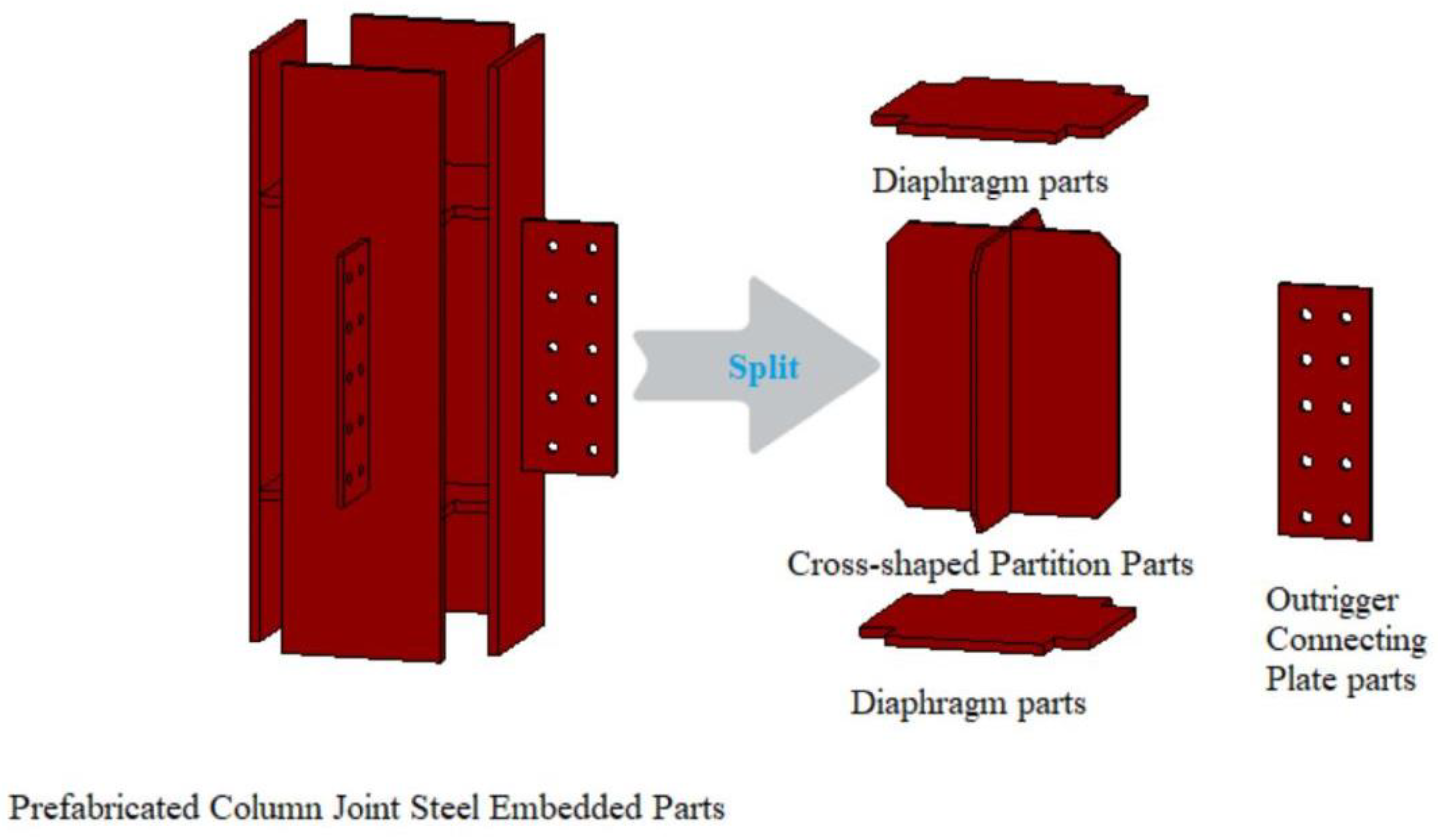
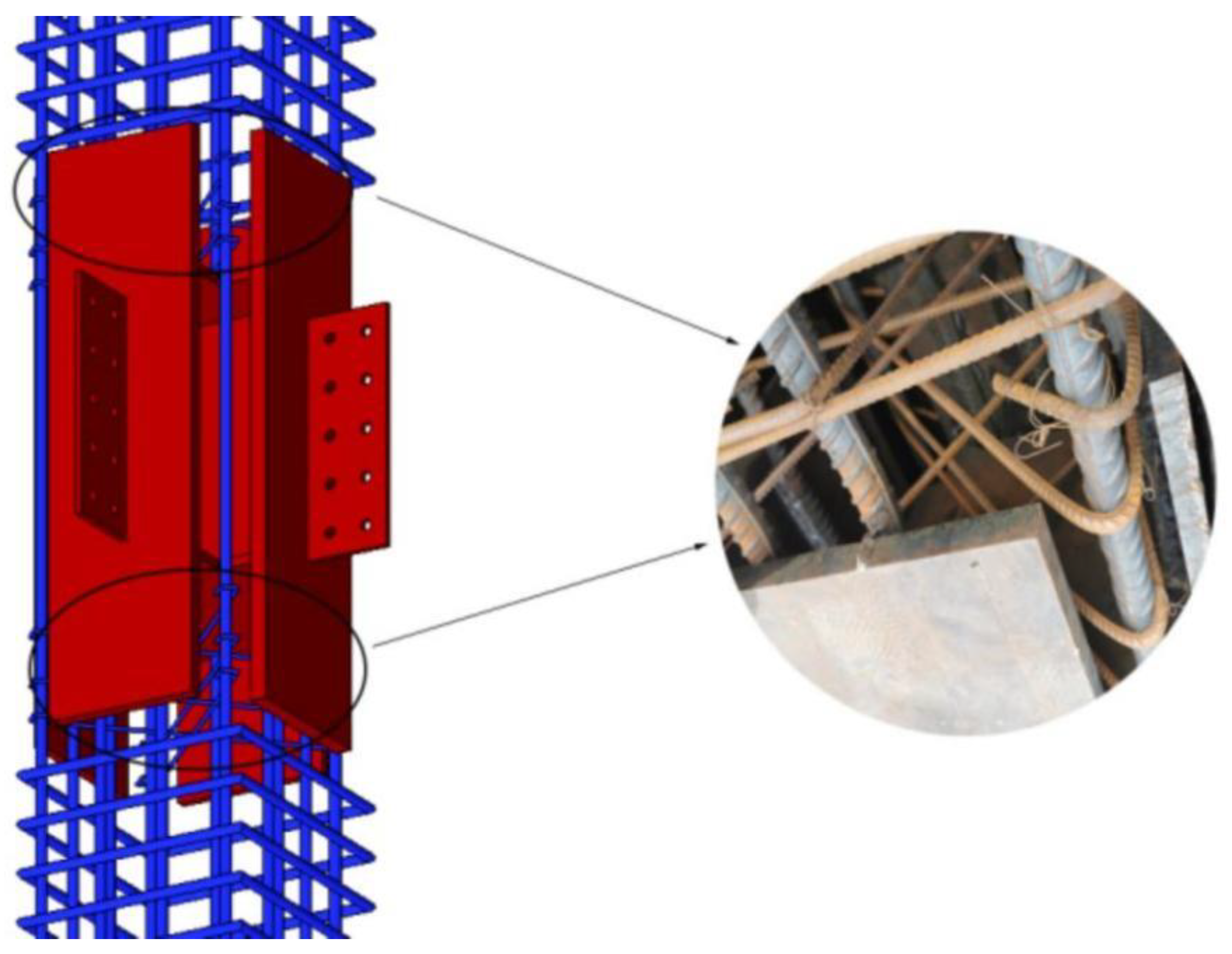
Therefore, this study introduces the design and manufacture of precast members used in precast concrete structures with steel joints in accordance with building engineering examples. In steel-member precast concrete structure buildings, the precast columns are in the form of reinforced concrete, and the steel members are embedded only at the beam-column joints. The steel member is a square steel skeleton composed of a diaphragm, a cross-shaped partition, and an extension connecting plate with bolt holes, as shown in
Figure 4.
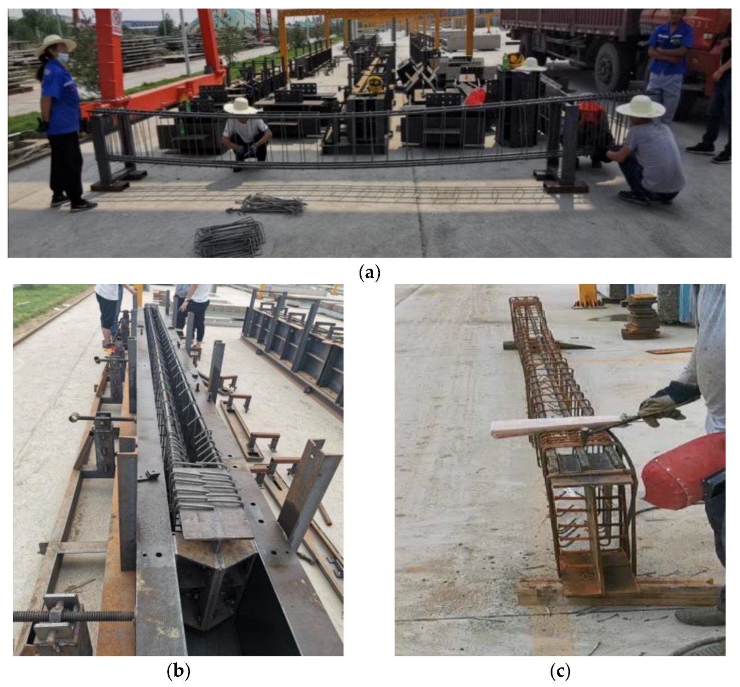
The all-steel mold is used in the production of the members. All the steel bars used in the precast columns are cut using industrial machinery and manually tied into steel frames. A diaphragm is located in the steel-embedded parts in the column members. Only the full-length longitudinal corner bars pass through the joint area of the precast column, and the steel skeleton composed of the central longitudinal steel bar and stirrups is divided into multiple sections by the joint. The multi-segment steel skeleton and the column nodal steel embedded parts are spliced outside the production mold, and the relative position between the rebar skeleton and the joint steel embedded parts is adjusted during the production of the column members. In addition, the longitudinal steel bar extending into the joint steel embedded parts and the vertical plate of the joint steel buried parts are welded on both sides. This requires that the weld length be no less than 10 times the longitudinal steel diameter of the column. Subsequently, the long corner bar is penetrated and tied. The connection between the steel reinforcement skeleton and the joint steel embedded parts is shown in
Figure 5.
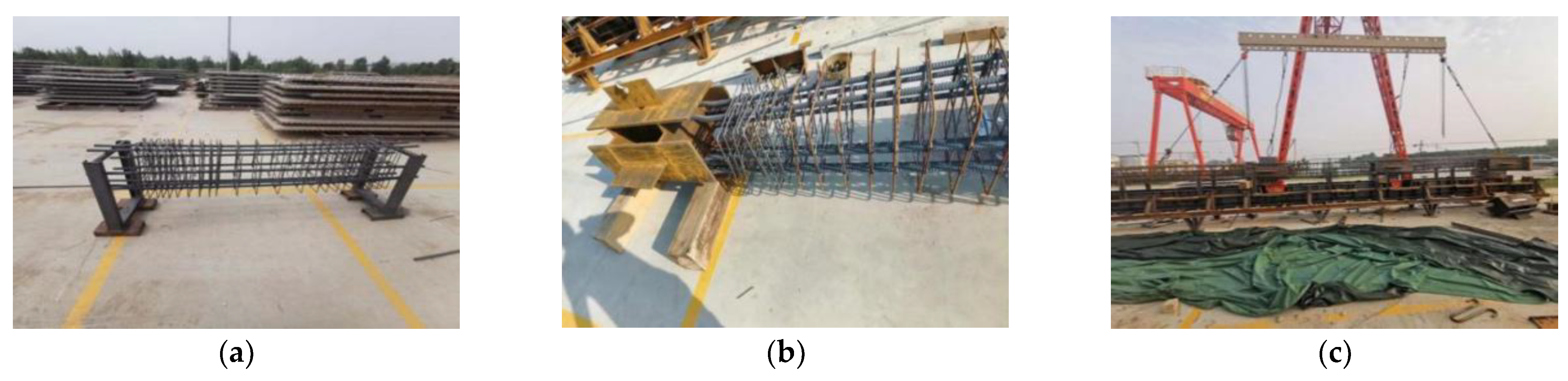
The crane hangs the precast column skeleton into the mold to pour concrete and completes the manufacture of the precast column components. The production process of the precast column is shown in
Figure 6.
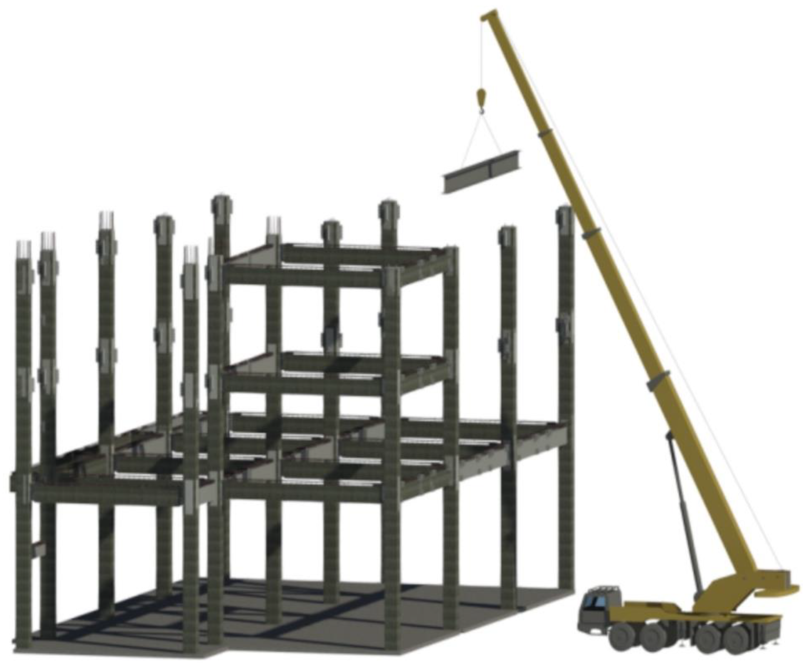
Because the system is mainly suitable for multi-story precast buildings, the general steel-joint precast concrete frame buildings use non-spliced precast column members to improve the assembly efficiency of the main frame of the building (
Figure 7). The inability of non-spliced precast column members to properly resist lateral effects in construction can be effectively solved by using oblique supports to fix the precast columns in building construction.
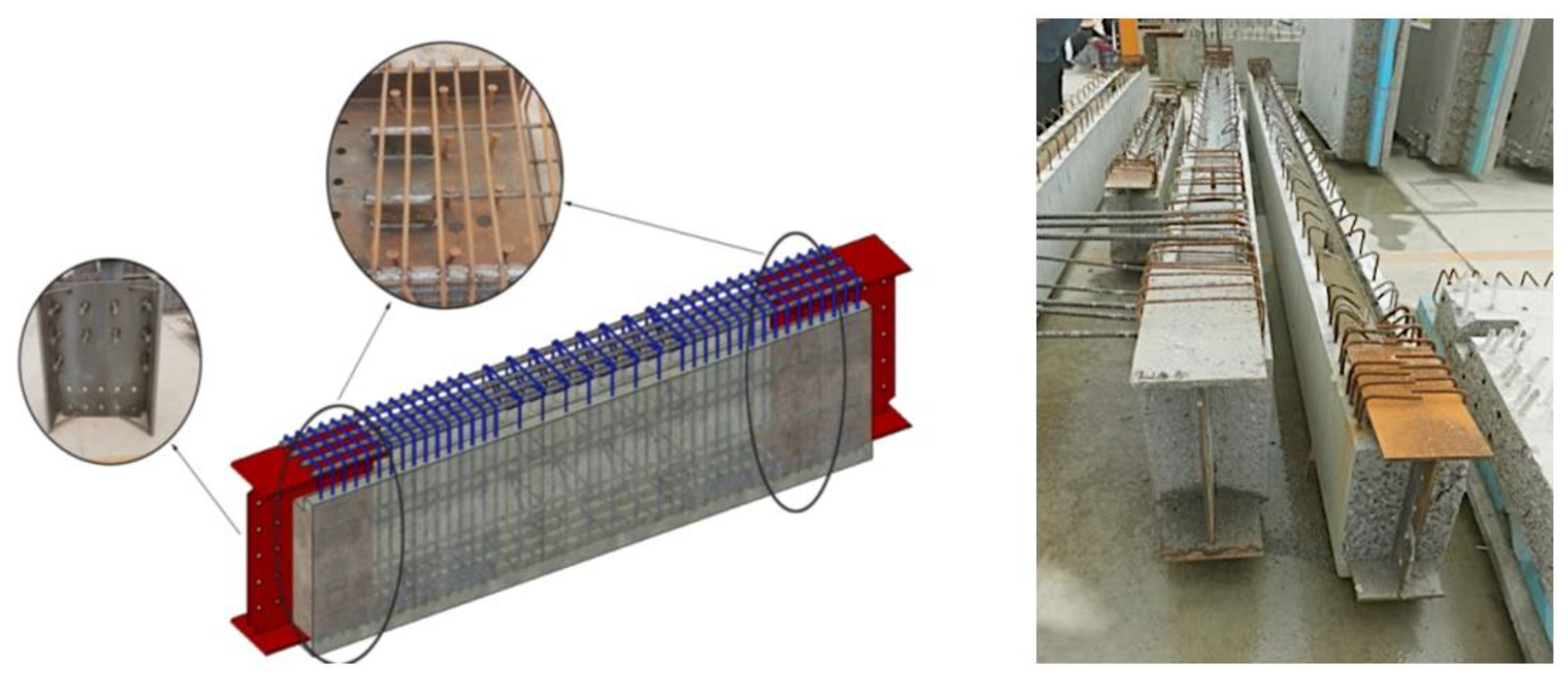
In the project, the precast concrete structure system with steel joints adopts composite precast beam members, and the top of the beam protrudes part of the steel bar skeleton into the building floor to reduce the weight of the members and increase the height of the building floor. During construction, the precast beam laminated layer is poured together with the building floor slab. Simultaneously, H-shaped steel with web openings is embedded at both ends of the beam, and the H-shaped steel flange is welded with the longitudinal steel bar in the beam on both sides. The weld length should not be less than 10 times the longitudinal bar diameter of the beam. The precast beam members are shown in
Figure 8.
The steel frame of the beam is first tied up in the production process of the precast beam. Next, the H-shaped steel embedded parts are inserted into the mold at both ends of the skeleton because tools in the mold can accurately locate the positions of the buried parts of the H-shaped steel and ensure the finished product of the precast beam members. It can meet the assembly accuracy requirements of the components.
The relative position of the steel bar skeleton and the H-section steel embedded parts is adjusted according to the requirements of the welding length of the H-section steel flange and the longitudinal steel bar in the beam. Owing to the small space in the mold, the welding operation cannot be completed. Therefore, the relative position of the reinforcing steel frame and the H-shaped steel embedded parts should be fixed by spot welding, then the mold is hoisted out as a whole for the welding operation. Finally, the beam precast components are hoisted into the mold to pour concrete to complete the fabrication of the precast beam components. The production process is shown in
Figure 9.
2.3. Connection of Precast Column and Precast Beam
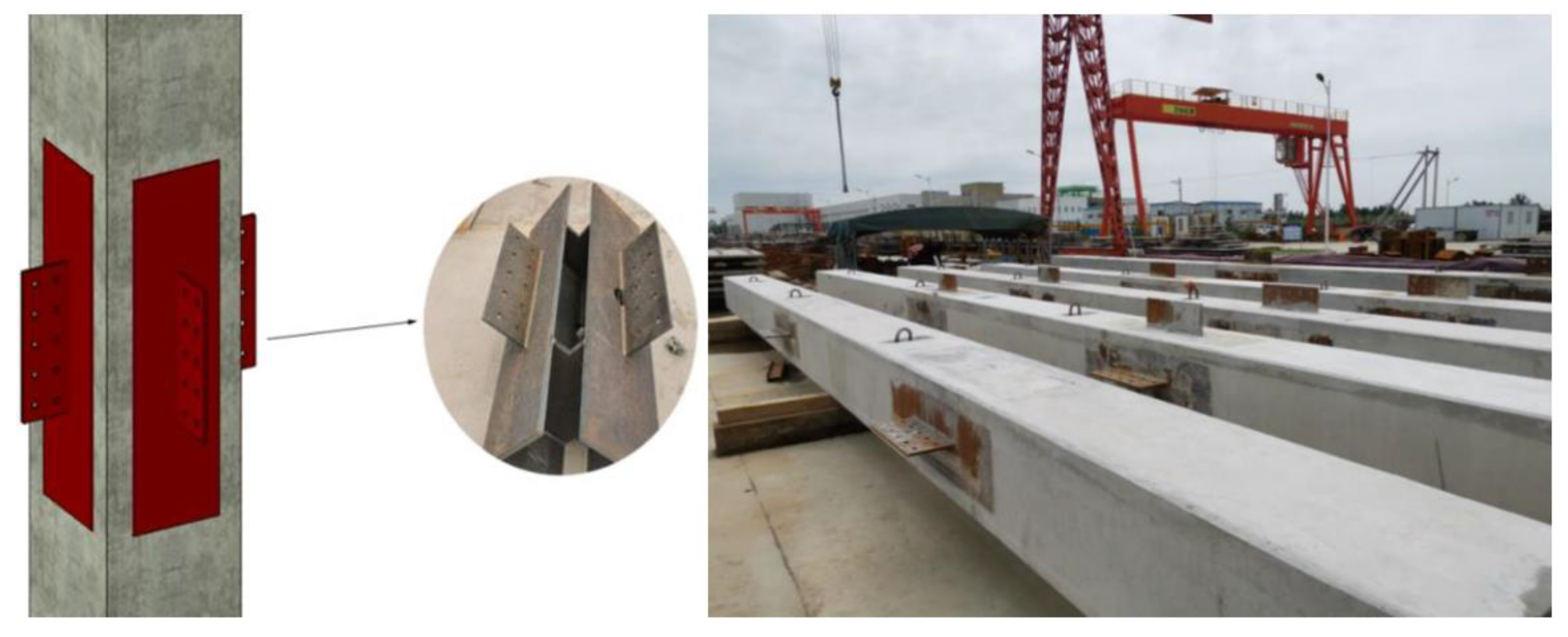
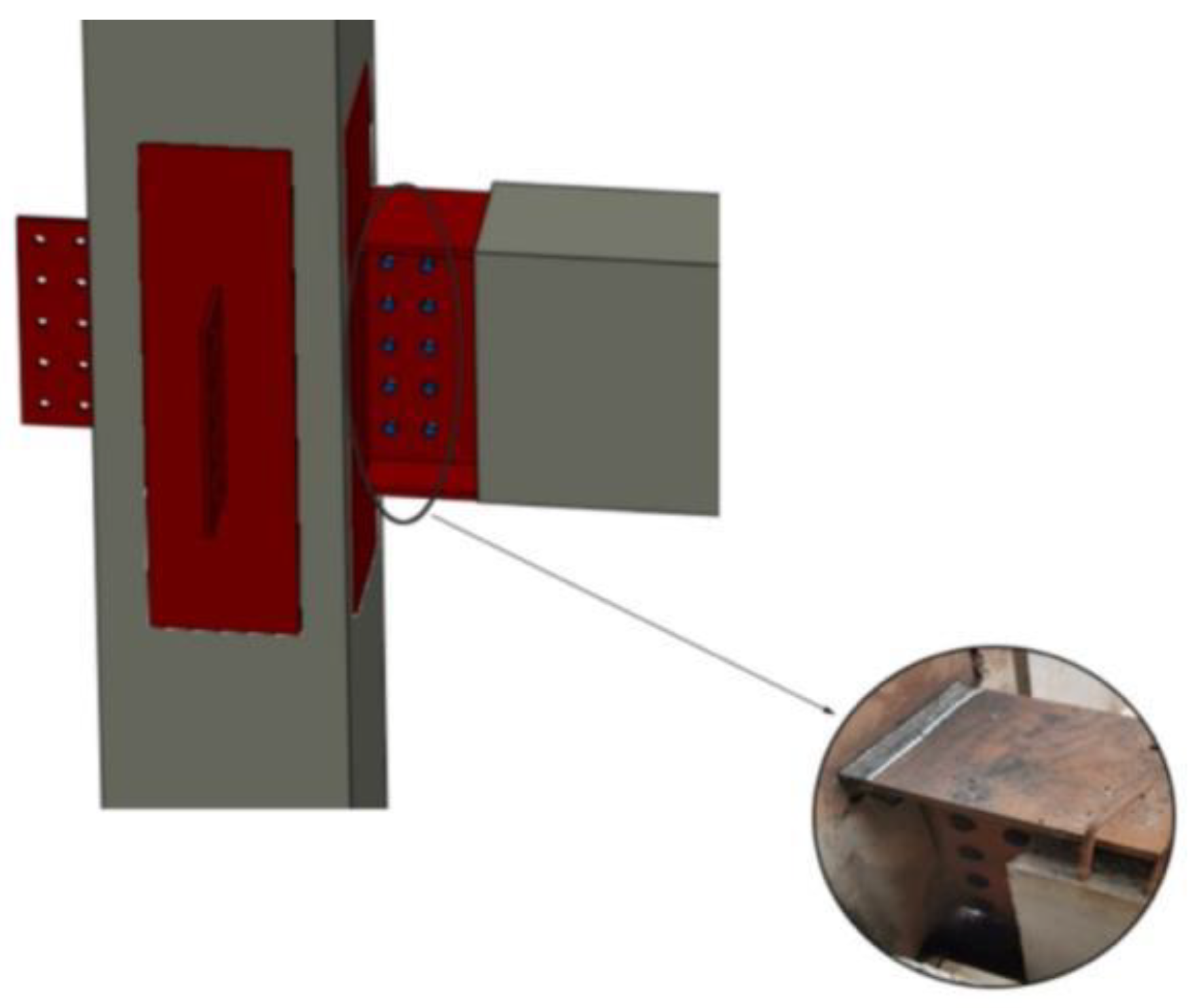
All beam-column precast members of the steel-joint precast concrete structures adopt the steel structure connection mode of bolting and welding. Specifically, the outrigger connecting plate of the square steel skeleton at the joint in the precast column and the web plate of the H-shaped steel at the beam end of the precast beam are threaded with high-strength bolts at the corresponding bolt holes. The upper and lower flanges of the H-shaped steel are welded and connected with the wall of the square steel skeleton. The connection is shown in
Figure 10. During the construction of the steel-joint precast concrete structure, the installation of beam-column components is not limited by the construction of the floor slab. Simultaneously, no supporting formwork is needed, and concrete is poured at the joint connection parts. Therefore, during construction, precast columns can be integrally installed first. Second, precast beams and precast columns are spliced to form the main frame of the building, and then floor construction is conducted. The connection mode of this component has significantly reduced the manual requirements and construction period. The construction of the steel-joint precast concrete structure is shown in
Figure 11.
The connection between reinforced concrete members is changed into the connection mode of steel structures, so it is easy to figure out the inconvenient connection between prefabricated reinforced concrete members using wet connections. For this fabricated structure system, the welding and high-strength bolt connection construction technology of steel structures is mature and reliable, which is convenient for the inspection and detection of the connection joint. Meanwhile, the original professional team of steel structure construction can be used for construction, which does not exceed the existing construction installation and construction management level. Hence, it is suitable for the quality of domestic existing construction and management and can effectively reduce the project cost.
2.4. Key Technologies in Construction
The construction process and key technologies of this steel-joint precast frame system were shown in
Figure 12.
- (1)
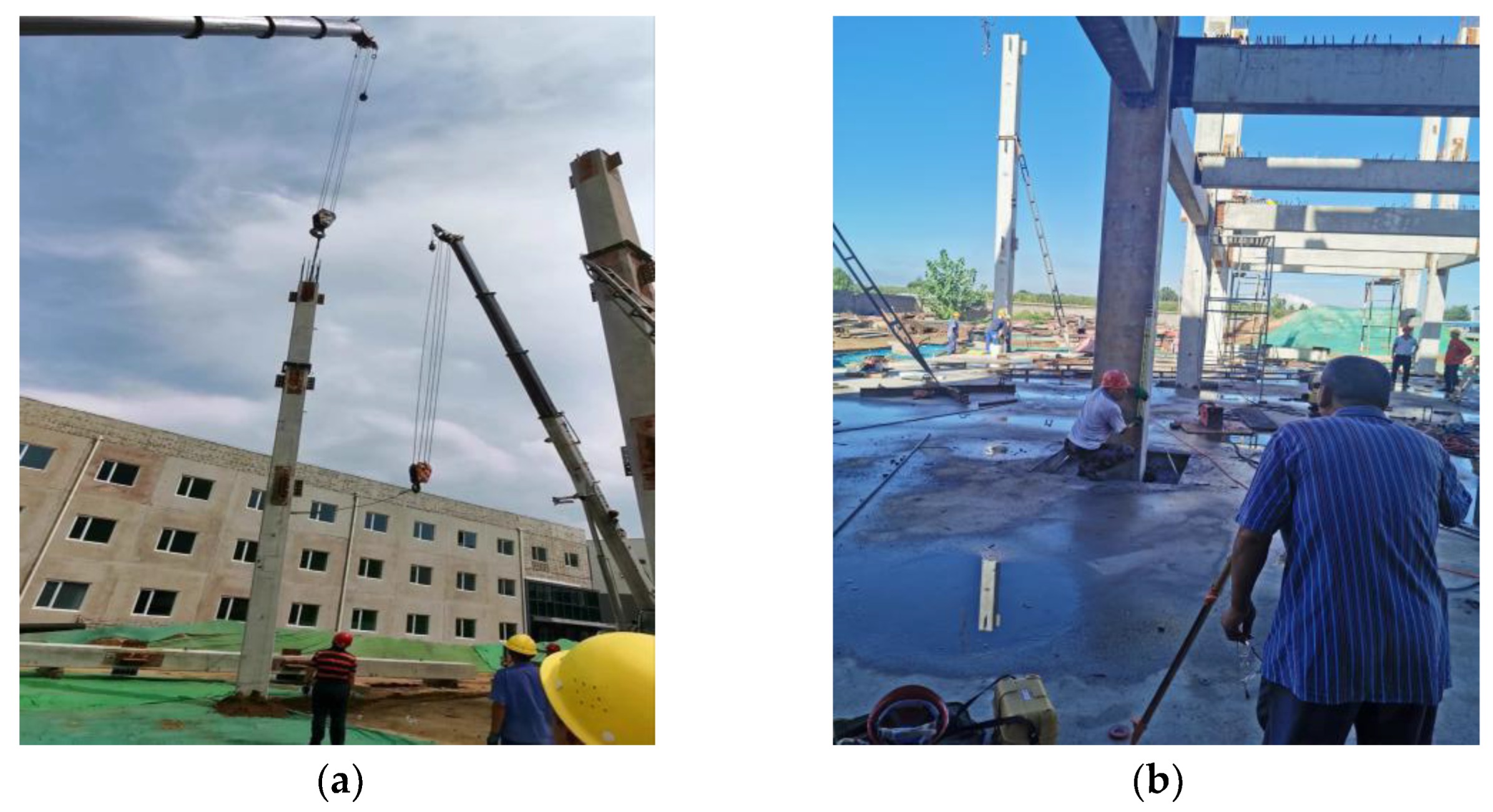
The reinforced concrete precast column members used in the project have large slenderness ratios and deadweight, which easily produce brittle fractures in the hoisting process. Hence, the precast column members are hoisted smoothly into the corresponding foundation of the cup mouth by two truck cranes.
- (2)
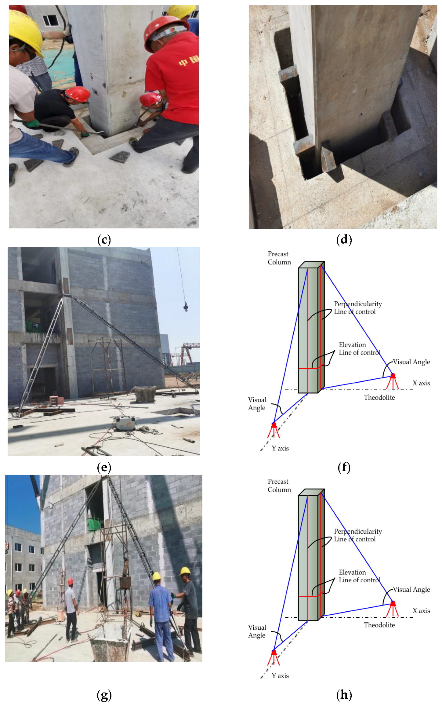
The accuracy control of precast column installation in the project is ensured by the installation control lines placed on the cup base and column before the construction stage. During the construction process, the truck crane was used to pull the precast column and cooperate with the on-site workers to finely adjust the installation position of the precast column in the cup foundation. After the adjustment, steel wedges were built into the cup foundation to constrain the horizontal displacement of the precast column. In addition, verticality control of the precast column by installing inclined support adjustment in the scape, oblique support that is built in on both ends can be adjusted by adjusting the screw support length on the transverse and longitudinal axis of the installation of the prefabricated column, respectively; the verticality control line on the scape erects theodolite observation, and on the basis of the scape verticality control line in the theodolite eyepiece deviation in adjusting inclined support, verticality controls scape.
- (3)
In order to improve the fault tolerance rate of precast components, the connecting plate of precast column steel joints is prepared during construction, the connecting plate is welded during the construction of beam and column components, and the connection deviation of the beam and column components can be partially adjusted through the weld.
3. FEM Simulation for Staged Construction and Monitoring Scheme
In the construction stage, the stress and deformation status monitoring of key parts of the structure can provide a timely grasp on the deformation trend of the structure, visualize the structural damage and the parts with hidden risks, and effectively reduce the construction risk. This section conducts finite element simulation analysis on the construction process of the test project. According to the simulated data, it analyses the stress variation law of precast concrete frame structure with steel joints during construction, detects the structural parts with construction risks and hidden dangers, and warns the actual construction. On the other hand, the secondary structure construction of steel-joint prefabricated concrete frame structure is monitored, and the stress and strain changes in the beam-column joint area are analyzed during the construction. By comparing the monitoring data with the simulated data, it can provide a safety guarantee for the construction and provide scientific experience for the construction monitoring of similar building structures in the future.
3.1. FEM Simulation for Staged Construction
In this study, the “life-and-death unit” technology in ABAQUS finite element software was used to simulate the construction process of the prefabricated concrete frame structure building with steel joints. Due to the rapid construction speed of steel-joint prefabricated concrete structures, the simulation process does not consider the influence of time-varying factors, such as concrete creep and temperature on the construction. During the simulation, the working load is divided into constant load and construction live load, and the engineering entity (filled wall) that does not participate in the calculation is equivalent to the constant load applied to the main frame of the building. The construction live load is 2 kN/m2, which is applied to the building floor in the way of uniform load distribution. An 8-node linear 6-dihedral reduction and integration element (C3D8R) was used for concrete and steel, and a 2-node linear 3-dimensional truss element (T3D2) was used for reinforcement.
The plastic damage constitutive is considered for concrete, and the reinforced double oblique constitutive is considered for steel members and rebar materials. The connection between the upper and lower flange of H-shaped steel at the beam end and the square steel pipe of the column are defined by the Tie constraint instruction. The tangential action of face-to-surface contact is defined as a penalty, and the normal action of face-to-surface contact is defined as hard contact.
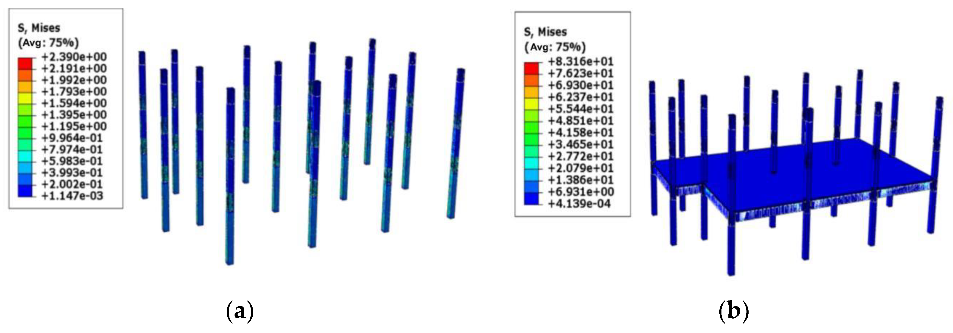
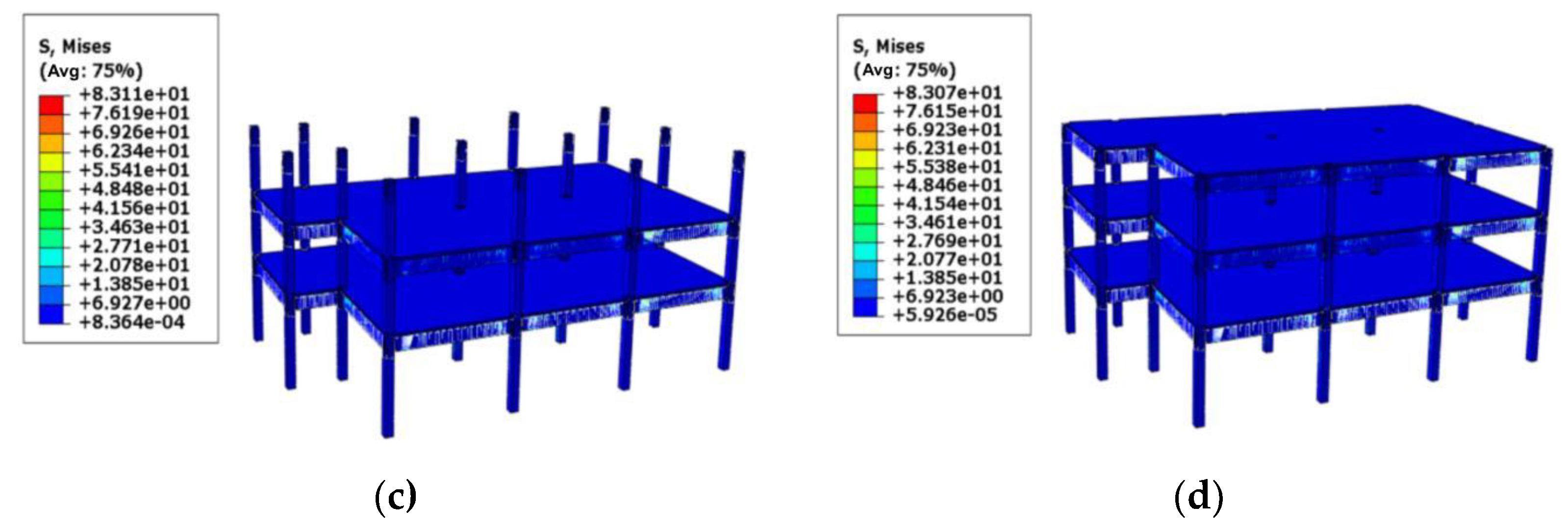
In the simulation of this project, the main frame model of the building is first established, and then the components that have not been built in the current analysis step are “killed” from the current analysis step of the model, according to the real working conditions, and then the corresponding units are gradually “activated”, according to the actual construction sequence. The construction simulation process of the main frame of the building is shown in
Figure 13 and
Figure 14.
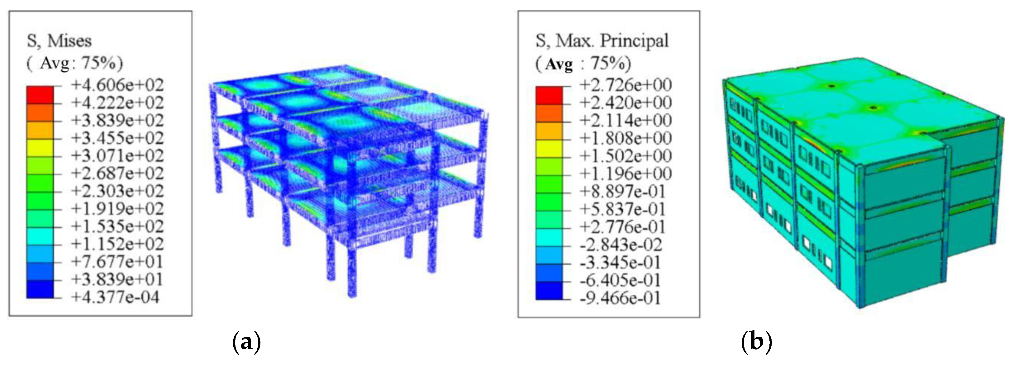
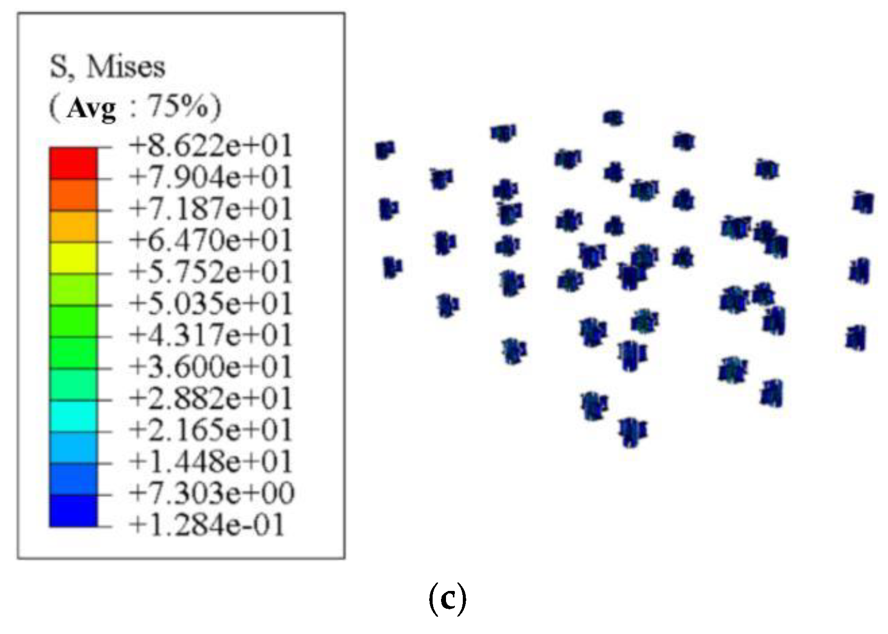
The stress cloud diagram of the final stage of construction is shown in
Figure 15. In the final stage, the stress value of each component reaches the maximum, so as to measure the safety of construction.
The stress of reinforcement is generally smaller than the tensile strength of 360MPa to HRB400 steel bars, and only the yield strength of the first-floor slab is slightly higher than that of HRB400. According to the maximum principal stress cloud diagram of concrete, the compressive stress of concrete components is much lower than the compressive strength of C30 concrete material, and most components are in the linear elastic stage during the construction process, which indicates that the construction process is safe and reliable.
3.2. Monitoring Scheme
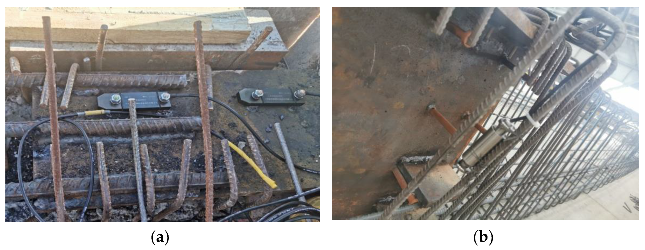
In this project, according to the different monitoring positions of strain gauges, two kinds of resistance strain gauges with different applicability are selected, which are, respectively, YBM tool-type surface strain sensors welded on the surface of the steel joints of beam-column members and YNM-type embedded strain sensors tied together with the steel cage of beam-column members, as shown in
Figure 16.
The measurement point arrangement in the scheme is to select the connected corner column, side column, and middle column in the building to form a small frame structure instead of the overall arrangement of measurement points in the building. The beam-column connection points with the largest stress in the small frame structure are selected as the representative measurement point, which is used to study the stress state of the whole construction process of the building structure.
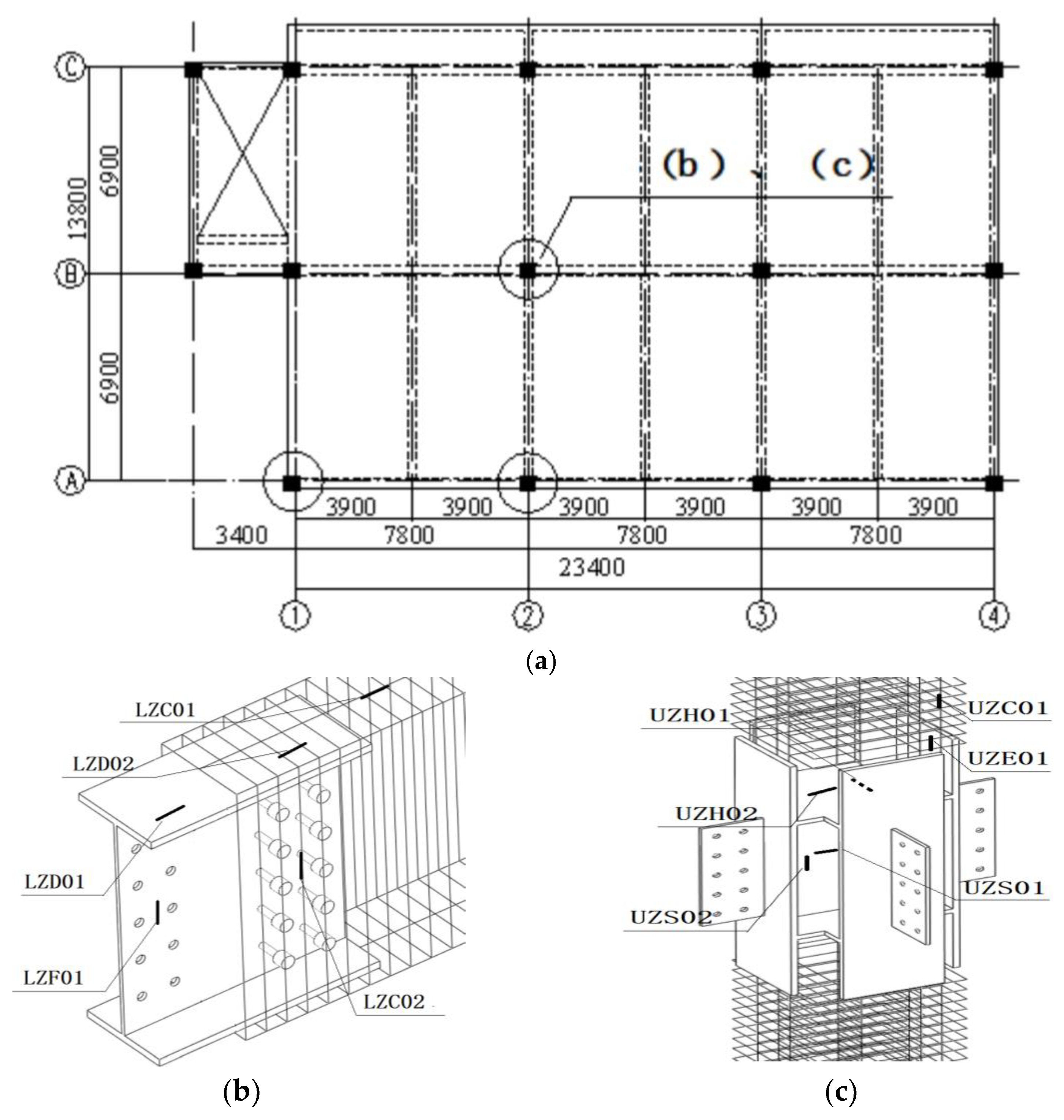
The plan of the first floor is shown in
Figure 17a. In this project monitoring scheme, the frame system surrounded by four axes of A, B, 1, and 2 in the plan is selected. The number of beam-column connection points monitored in the frame is three, all on the first floor of the building, and the location of monitored nodes are marked by a circle in
Figure 17a. In the monitored beam-column connection joints, a total of eight YBM tool-type surface strain sensors are welded on the square steel tube embedment of each joint and the beam-end H-shaped steel embedment is connected with it. In addition, three YNM-embedded strain sensors are embedded in each point area on the reinforcement skeleton. There are 33 visual inspection points in this project. The number of measuring points is shown in the following table. The letters represent the position of measuring points; the details are as follows.
U stands for the column, L stands for beam, Z stands for middle column point, B stands for side column point, J stands for corner column point, H stands for horizontal plate, S stands for cross plate, E stands for vertical plate, C stands for measuring point in concrete, D stands for top of the upper flange, F stands for web, and the number of measuring points is shown in
Table 2.
The sensor arrangement position in each monitoring point area is the same. Taking the beam-column connection point of the middle column as an example [
28], the detailed arrangement of measuring points in the joint is shown in
Figure 17b,c.
From the completion of the main structure to the completion of the project, daily periodic monitoring is carried out to analyze the structural state of the strain and stress changes subject to the gradually increasing construction load. The construction schedule node is shown in
Table 3.
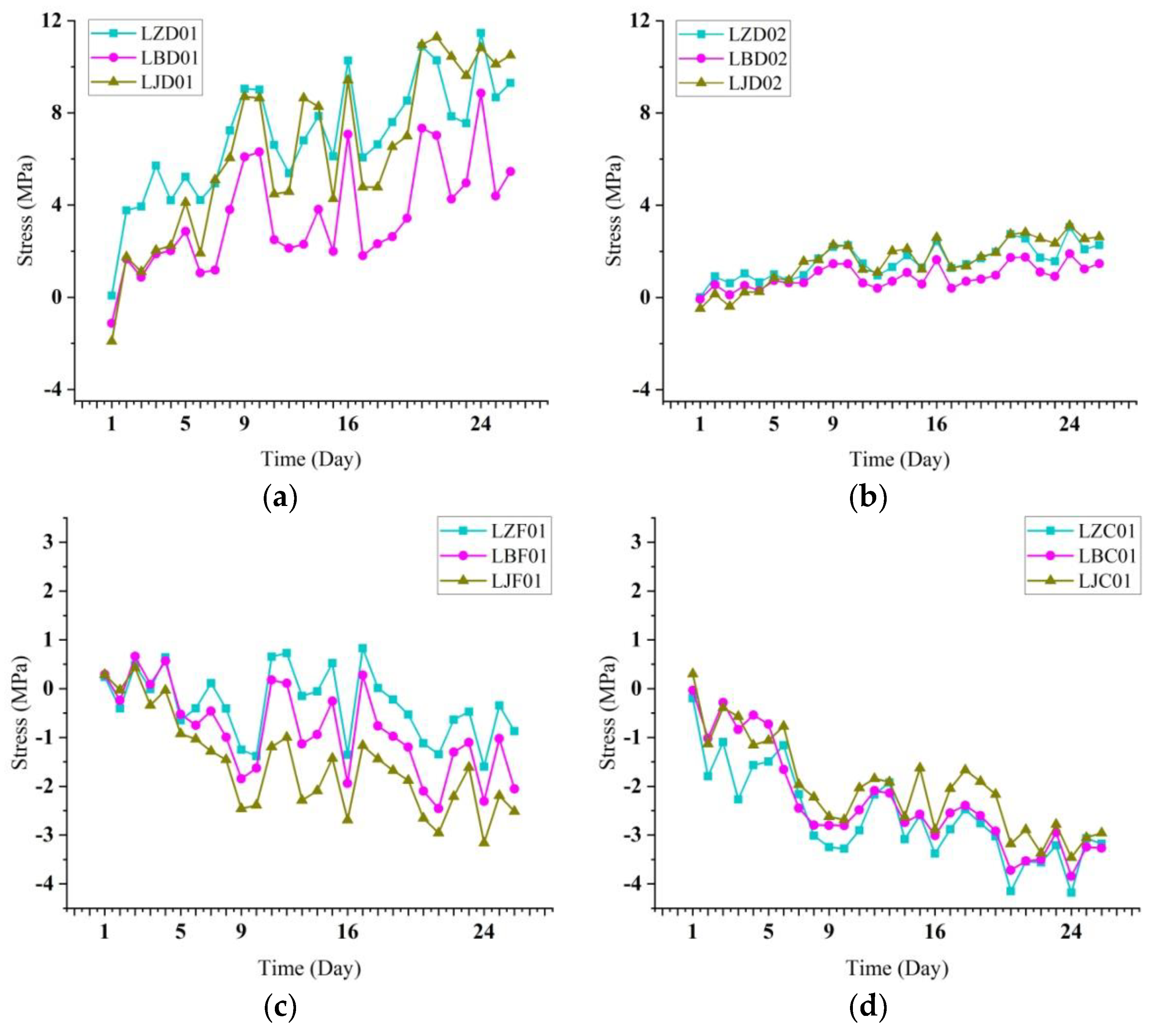
By comparing the stress changes at the same measuring point of each precast beam monitored on the first floor of the building, as shown in
Figure 18, the analysis shows that:
- (1)
The stress values of the measured points at each beam end are relatively discrete and the stress curves deviate significantly, which is mainly caused by the uneven distribution of the construction load on the building floor and the irregular loading and unloading during the construction. The stress fluctuation intervals of the measuring points of the steel section on the upper flange, reinforced concrete section on the upper flange, and web of H-shaped steel at each beam end are −2–12 MPa, −0.5~3.5 Mpa, and −3.5~1.5 MPa, respectively. The stress fluctuation intervals of the measuring points on the top of the concrete section at each beam end are −4.5~0.5 MPa. It can be seen that the stress change of the beam end in the construction of the secondary structure of the building is far less than the yield strength of the steel and concrete materials used in the building.
- (2)
The stress variation at the same measurement point of each beam end during construction is basically the same, and the absolute value of stress shows a deviating upward trend, indicating that the precast beams of the building can work well together.
- (3)
The stress value of steel section on the upper flange of H-shaped steel at the end of each beam is generally higher than that of the reinforced concrete section, and both of them show tensile stress. The compressive stress was observed at the top of the concrete section at each beam’s end. It can be seen that the stress state of the precast beam of the steel-joint prefabricated concrete frame structure during construction is that the beam end presents negative bending moment, and the bending moment gradually becomes positive when extending from the beam end to the middle of the beam span. At the same time, it is found that the stress value of each measuring point at the beam end has no obvious mutation, indicating that the connection state of the monitored frame nodes under the action of construction load is good, and no risks, such as unwelding or bolt slip, occur.
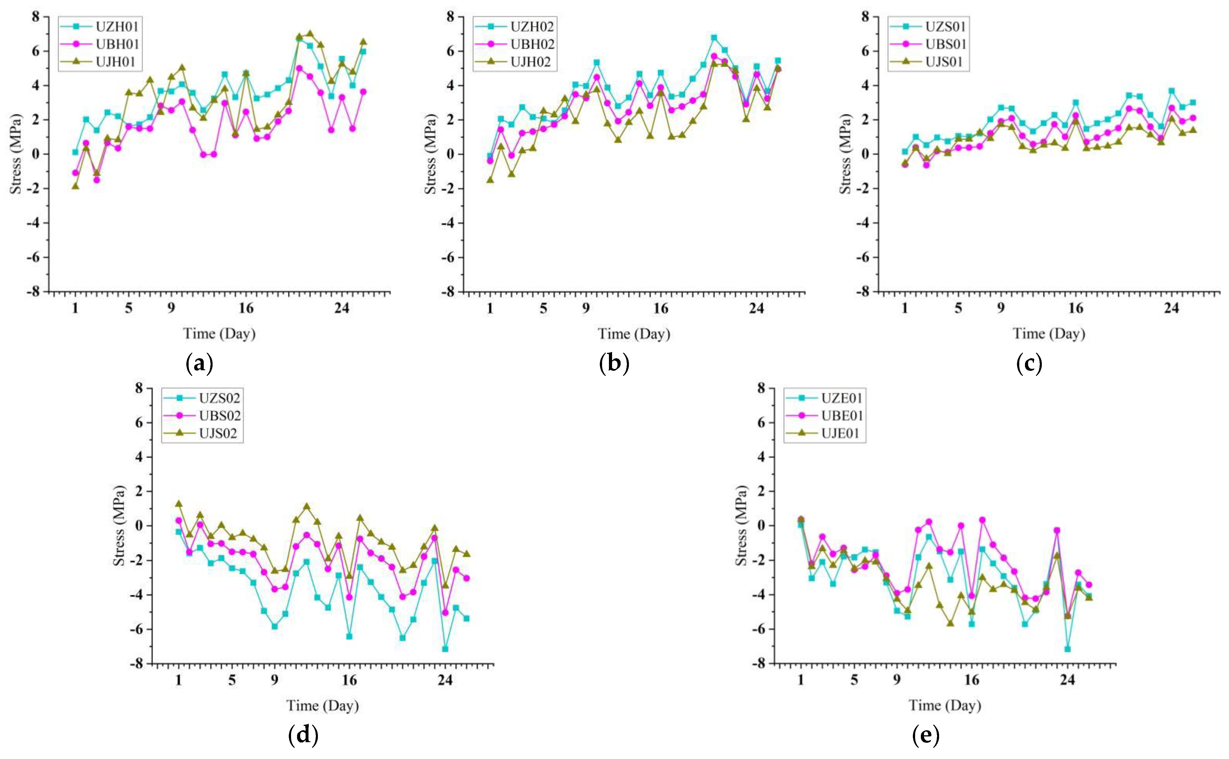
By comparing and analyzing the stress data of the measuring points of the steel joints of the middle column, side column, and corner column in the construction process, as shown in
Figure 19, it can be seen that:
- (1)
The stress curve of each measurement point is rather meandering, but the range of stress fluctuation is small, which is caused by construction material handling and stacking on the building floor. The stress fluctuation range of horizontal plate 01, horizontal plate 02, cross partition 0°, cross partition 90°, and a vertical plate of each column steel joint in the construction process of the secondary structure is −2~8 MPa, −2~7 MPa, −1~4 MPa, −8~2 MPa, and −8~1 MPa, respectively. The maximum stress variation is about 10 MPa, which is much lower than the yield strength of Q345 steel used for steel joints. Combined with the analysis of the stress fluctuation range of each beam end measurement point, it is concluded that in the construction of the secondary structure of the building, the stress of the frame node position does not change much, and the safety of the building is not greatly affected.
- (2)
Each column steel measuring point with the same location has almost the same stress changes; the absolute value of the stress is winding up trends, which, combined with the analysis of the stress curve of the beam end of the same measuring point, indicates that the prefabricated concrete frame structure in steel point and edge point have the same angle in the same state of stress changes in the process of construction, which further indicates that the construction of each point can work better together. At the same time, according to the stress data of each column’s steel joint in the building, the stress value of the middle point is generally the largest, while the stress value of the corner point is generally the smallest. This is because the force transmission path of the frame structure is from the floor to the column and then from the beam to the column. Therefore, the number of columns connecting the beams is large, and the stress is also generally large. The data show that the stress value of some measuring points of the corner column steel joints is greater than that of middle column steel joints, which is due to the occurrence of construction loads, such as building filling walls, concentrated in the measuring point area of the corner column steel joints, resulting in a larger stress value of some measuring points of the corner column steel joints.
- (3)
Through the monitoring data, it is found that the stress change trend of measurement points 01 and 02 of the steel-joint horizontal plate of each column is the same, which is the tensile stress of tortuous growth. At the same time, through the monitoring data of each column steel-joint cross partition and vertical plate, it can be seen that the cross partition is subjected to horizontal tensile stress and vertical compressive stress, while the vertical plate is mainly subjected to compressive stress. The results show that steel joints can play a positive part in the stress work in the construction of building structures and play a positive role in improving the bearing capacity of joints.
3.3. Discussion
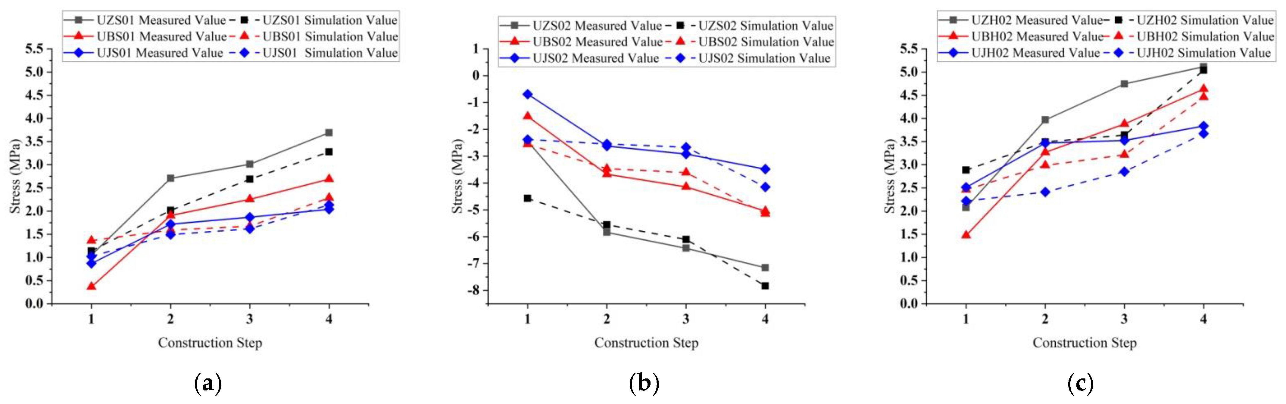
The stress simulation data of the measuring point unit under each construction step is obtained through the field variable output function of the software.
By comparing the monitored stress data and simulated stress data of measuring points under different construction steps, it is found that the simulated calculated value of each measuring point under different working conditions is generally less than the actual monitored value.
Figure 20 shows the comparison diagram of stress data of some measuring points. The main reason for the deviation between the monitored value and the calculated value is that several construction steps are carried out simultaneously in the actual construction, and the actual construction step is larger than the construction load in the simulated construction step. The site of the construction process with measured value and the simulation calculation of stress have the same change trend, numerical deviation within ±2 MPa, monitoring data, and simulated data in which the coincidence degree is higher; it shows that the finite element simulation analysis simulation steel-joint prefabricated reinforced concrete frame structure building in the construction phase of the stress change of the method is feasible, which provides theoretical support for the construction of the building.
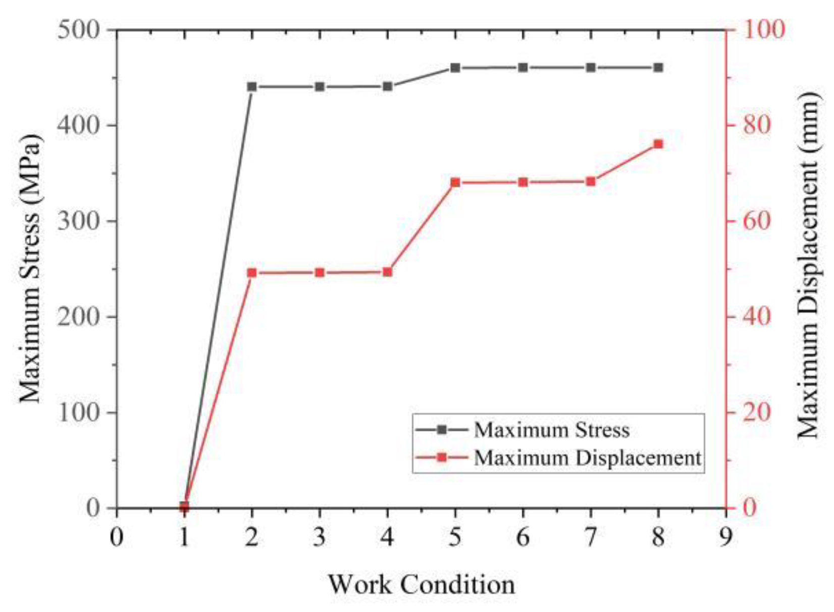
The stress variation trend reflects that the maximum tensile stress and the maximum compressive stress of the building model occur when the insulation layer of the top floor is laid, and the maximum stress value of reinforcement, steel, and concrete materials in the simulation process does not reach the yield strength of each material. It shows that the building structure has high safety in the construction process.
4. Construction Efficiency Analysis
The construction technology of conventional reinforced concrete frame structure (hereinafter, RC), precast concrete frame structure (hereinafter, PC), and steel-joint precast concrete frame structure (hereinafter, SPC) is analyzed based on the actual construction of the steel-joint precast concrete frame structure. The construction periods of the three structural systems are compared. Consequently, the construction period of the steel-joint precast concrete frame structure system is found to be the shortest. Compared with the conventional reinforced concrete frame structure, the construction period is reduced by 50–60%; compared with the precast concrete frame structure, the construction period is reduced by nearly 40%.
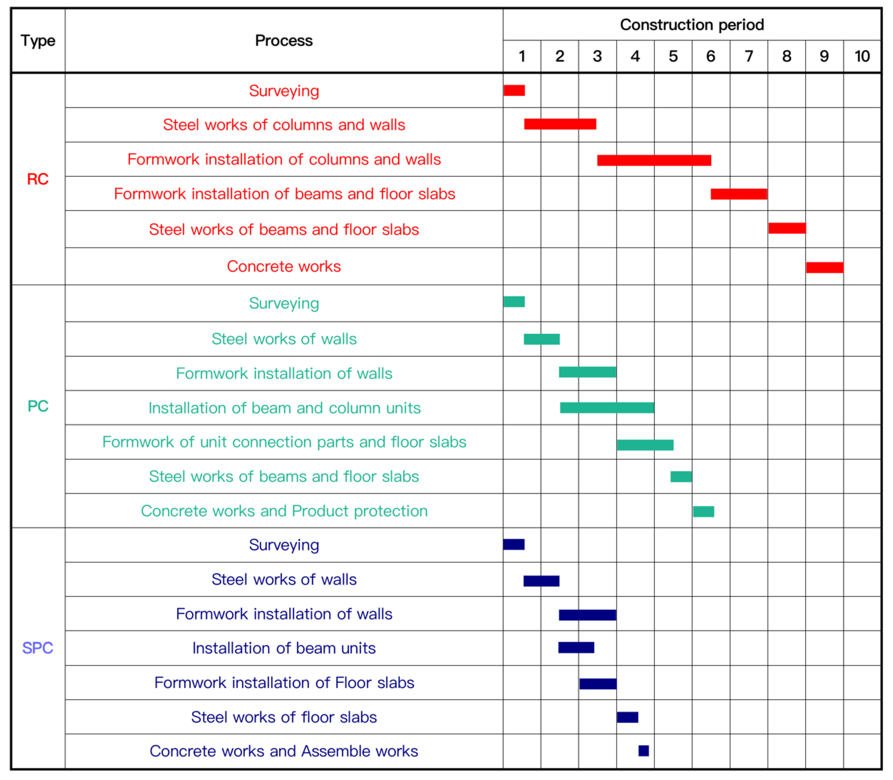
4.1. Comparative Analysis of Construction Process and Cycle
Based on the single-layer construction of the same frame structure building. The construction process of each type of structure is shown in
Figure 21.
The conventional construction procedure of a reinforced concrete frame structure building, in turn, includes surveying, steel works of columns and walls, formwork installation of columns and walls, formwork installation of beams and floor slabs, steel works of beams and floor slabs, and concrete works. The construction period of a single layer of a frame structure building is 9 days.
The construction process of a precast concrete frame structure building, in turn, includes surveying, steel works of walls, formwork installation of walls, installation of beam and column units, formwork of unit connection parts and floor slabs, steel works of beams and floor slabs, concrete works, and product protection. The construction process of this structure system frame building is tedious, but the mutual interference of each construction step is not strong, so multiple steps can be carried out simultaneously. Therefore, the construction period for completing a single layer of a frame structure building is 6.5 days.
The construction process of the steel-joint precast concrete frame structure is as follows in sequence: surveying, steel works of walls, formwork installation of walls, installation of beam unit, formwork installation of floor slabs, steel works of floor slabs, assembly works, and concrete works. The construction period for completing a single layer of a frame structure building is 3.8 days. Because precast column members need to be hoisted and installed during the first layer of construction of this structure system, the construction period for completing the first layer of the building is 4.3 days.
To compare the construction periods of the three structural systems more intuitively, this study introduces a four-story standard frame building as a calculation model. The construction of a model building with a steel-joint precast concrete frame structure system can be completed in 15.7 days, compared with the construction period of 26 days for the precast concrete frame structure system. Therefore, the construction period is reduced by 39.6%. However, the conventional reinforced concrete frame structure system needs 36 days to complete the project, and the construction period is reduced by 56.4%. Furthermore, compared with the conventional reinforced concrete structure system, the precast structure system mainly saves time in the construction steps of steel binding and formwork support, in addition to saving labor and building materials. As an update of the precast concrete structure system, the steel-joint precast concrete structure system mainly reduces the construction period from the assembly of precast components. Moreover, it reduces the use of building materials, such as formwork and concrete, and gradually evolves into a construction mode based mainly on machines and tools and assisted by manpower.
4.2. Anticipation of Perfecting Steel-Joint Precast Concrete Structure System
According to the construction period of the steel-joint precast concrete structure system given in
Table 1, the construction of walls and floors of the building accounts for approximately 70% of the total construction period. Therefore, when the steel-joint precast concrete structural system is applied to the framework building, the precast wall panels and floors are formed with the precast building, fully utilizing the advantages of the structural system. This further improves construction efficiency and reduces labor consumption. The fully precast components are more consistent with the steel-joint precast concrete structural system because the main frame of the structure building is formed quickly during construction. This is sufficient for providing the bearing capacity for the construction load introduced by the rapid installation of the precast components.
5. Building Energy Efficiency
Large amounts of energy are consumed in building construction as cities grow. According to the number of building materials consumed during the construction of different structural types of buildings, the basic energy consumption of each structural type of building is estimated with the energy amount consumed by the production of building materials as the basic unit [
36,
37,
38,
39,
40]. Taking a three-story framework structure as an example, the building energy consumption of the steel-joint precast concrete, conventional concrete, and precast concrete is calculated and compared. The calculation results are presented in
Table 4, indicating that the building energy consumption of the steel-joint precast concrete structural system is reduced by 22.2% and 19.1%, compared with the conventional concrete structure system and the conventional precast concrete structure system, respectively. The energy consumption of formwork is reduced by 54.9% and 22.5%, respectively, because the steel-joint precast concrete structure buildings only lay formwork in the floor construction, which greatly shortens the usage of formwork. When the structural system is perfect, the building adopts fully precast components, with a formwork energy consumption of zero, which further reduces the energy consumption of the building. Compared with the energy consumption of the conventional concrete structure system and conventional precast concrete structure system, that of reinforcement is reduced by 34.9% and 37.6%, respectively. In the beam-column connection joints, the dense steel bars are replaced with steel members due to the resistance to the shear forces, resulting in a reduction in the energy consumption of steel bars. Compared with the conventional concrete structure and precast concrete structure systems, the concrete energy consumption is reduced by 25.5% and 31.6%, respectively. This is because steel members embedded in the precast concrete structure of steel joints enhance the stiffness of each precast member, reducing the cross-section area of the members and reducing the usage of concrete in the building. In summary, the steel-joint precast concrete structure has certain advantages in building energy consumption.
6. Conclusions
This research elucidates the steel-joint precast concrete structure system, considering engineering practices. This structure system solves the assembly difficulties of the conventional connection mode for precast concrete components using steel connection. The key technologies for construction have been investigated for steel-joint fabricated concrete frame structures by using the methods of on-site supervision, stress monitoring, and numerical simulation. The main research contents and conclusions are as follows:
- (1)
The steel-joint precast concrete structure combines the steel and concrete structures effectively. With the quick and simple connection of beam-column members, the main framework may be completed at one time without wet construction. This building structure system can be widely used with high practical utility.
- (2)
Construction techniques, such as “piecewise casting”, “theodolite & oblique support” adjustment installation, and “lag-connect & lag-weld” installation of connecting plates, are proposed, which can solve engineering difficulties and improve construction efficiency.
- (3)
The main structure can work coordinately and can be better at forcing transmission performance works at an elastic state under the normal service condition. The comparison and analysis of simulation results and monitoring values show that the two development trends are basically the same, indicating that the construction monitoring and simulation method adopted is feasible, and the building has high safety during construction.
- (4)
Construction pile load has a significant influence on stress distribution. It is recommended to reasonably plan the placement of construction materials and tools in the construction process to avoid excessive concentrated load on the floor slab and safety accidents.
- (5)
For a single-story framework building, the construction cycle of the steel-joint precast concrete structure is only 3.8 d, which is a 39.6% and 56.4% reduction, compared with that of the precast concrete and reinforced concrete structures, respectively. The construction progress analysis shows that the precast system composed of precast floors and walls may further improve construction efficiency.
- (6)
Compared with the precast concrete and conventionally reinforced concrete structures, the steel-joint precast concrete structure generally reduces the amount of formwork, reinforcement, and concrete, lowering the building energy consumption by 19.1% and 22.2%, respectively.
The steel-joint precast concrete structure features low consumption of building materials, high assembly efficiency of precast components, and reduced energy consumption of construction equipment. This research on steel-joint precast concrete structure systems provides a reference for the development of precast concrete structures.


