
Experimental Investigation and Numerical Analyses on Cyclic Behavior of the Prefabricated Concrete Frame Infilled with CFS-CLPM Composite Walls
Abstract
:
1. Introduction
2. Experimental Program
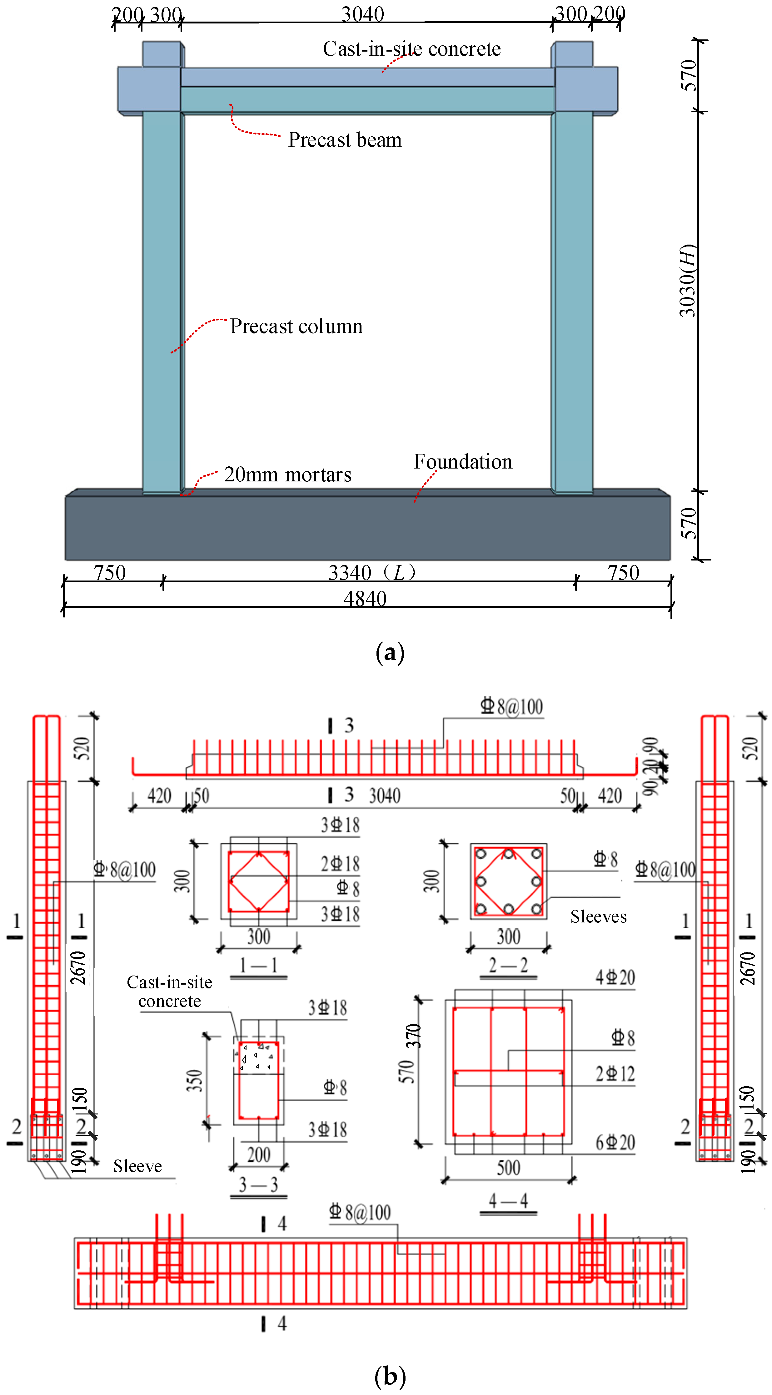
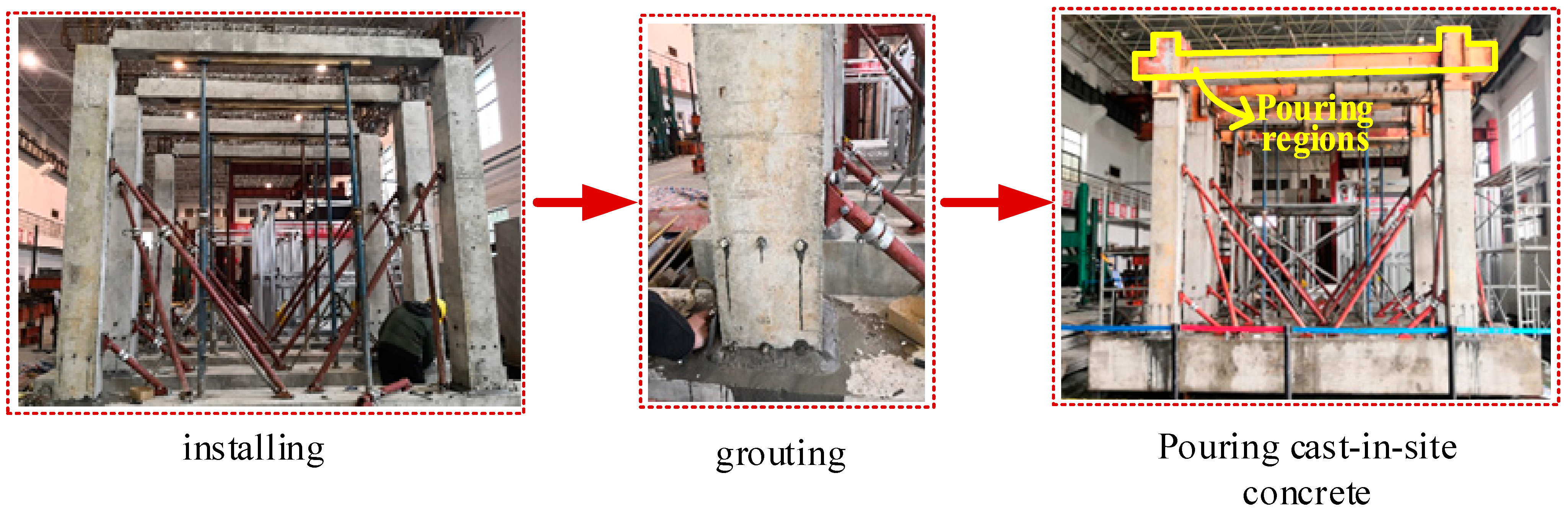
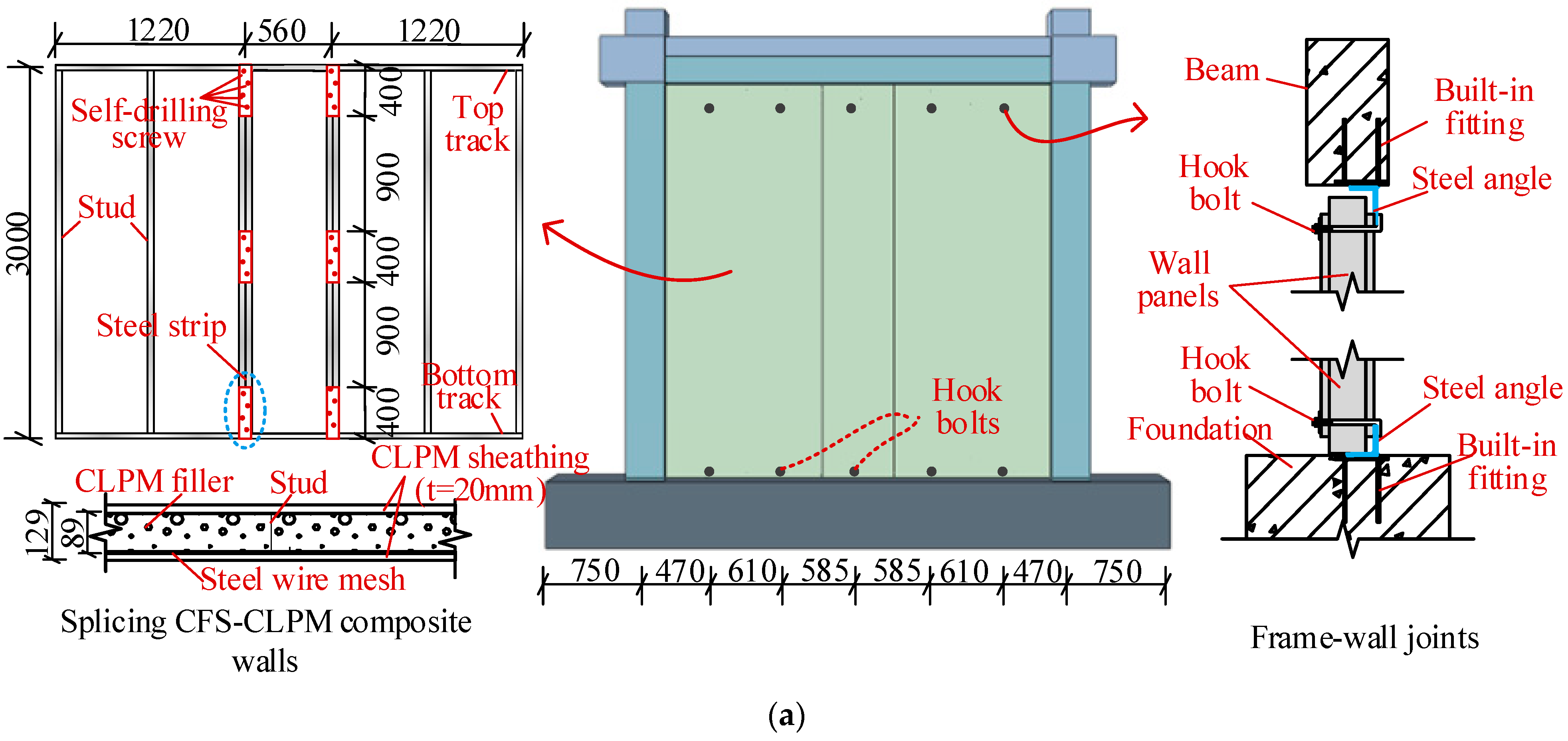
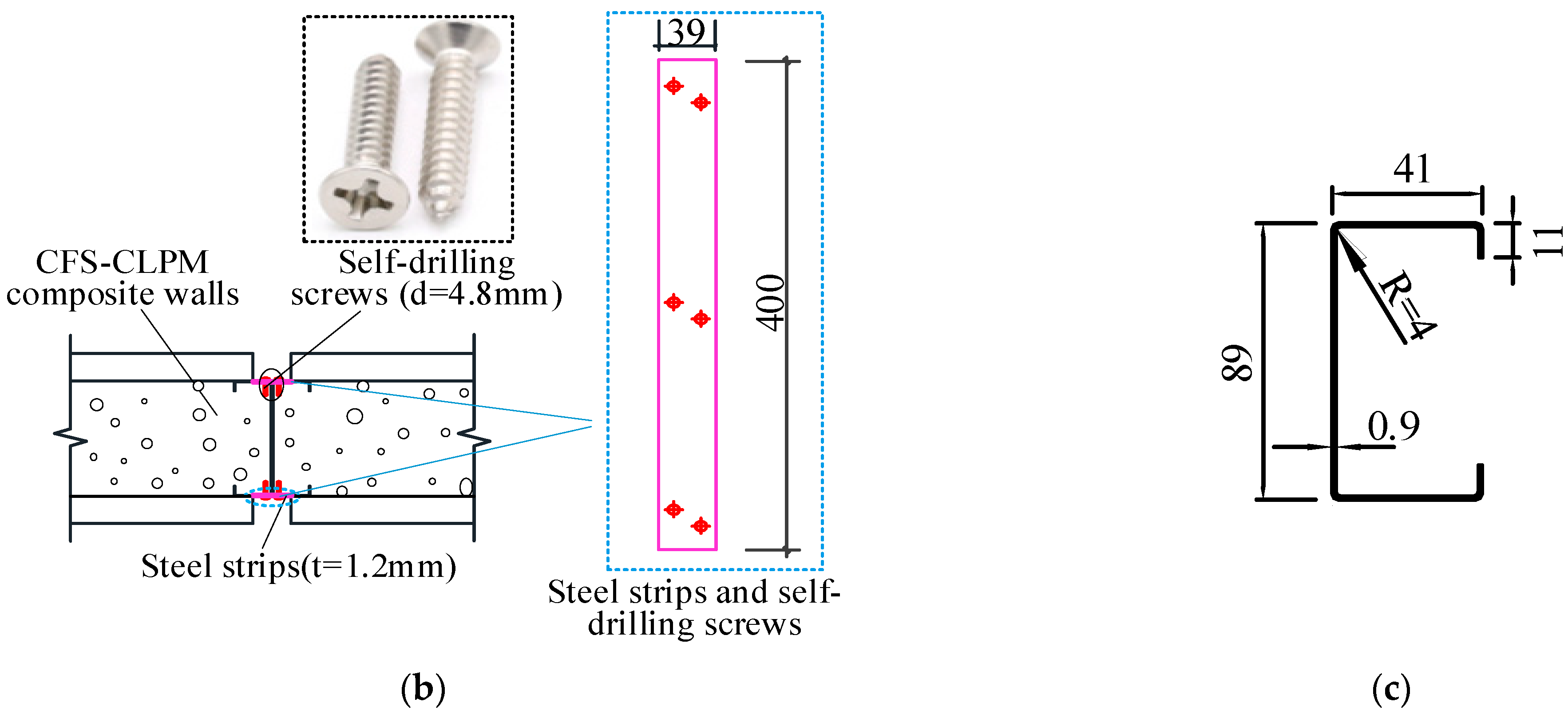
2.1. Test Specimens
2.2. Material Properties
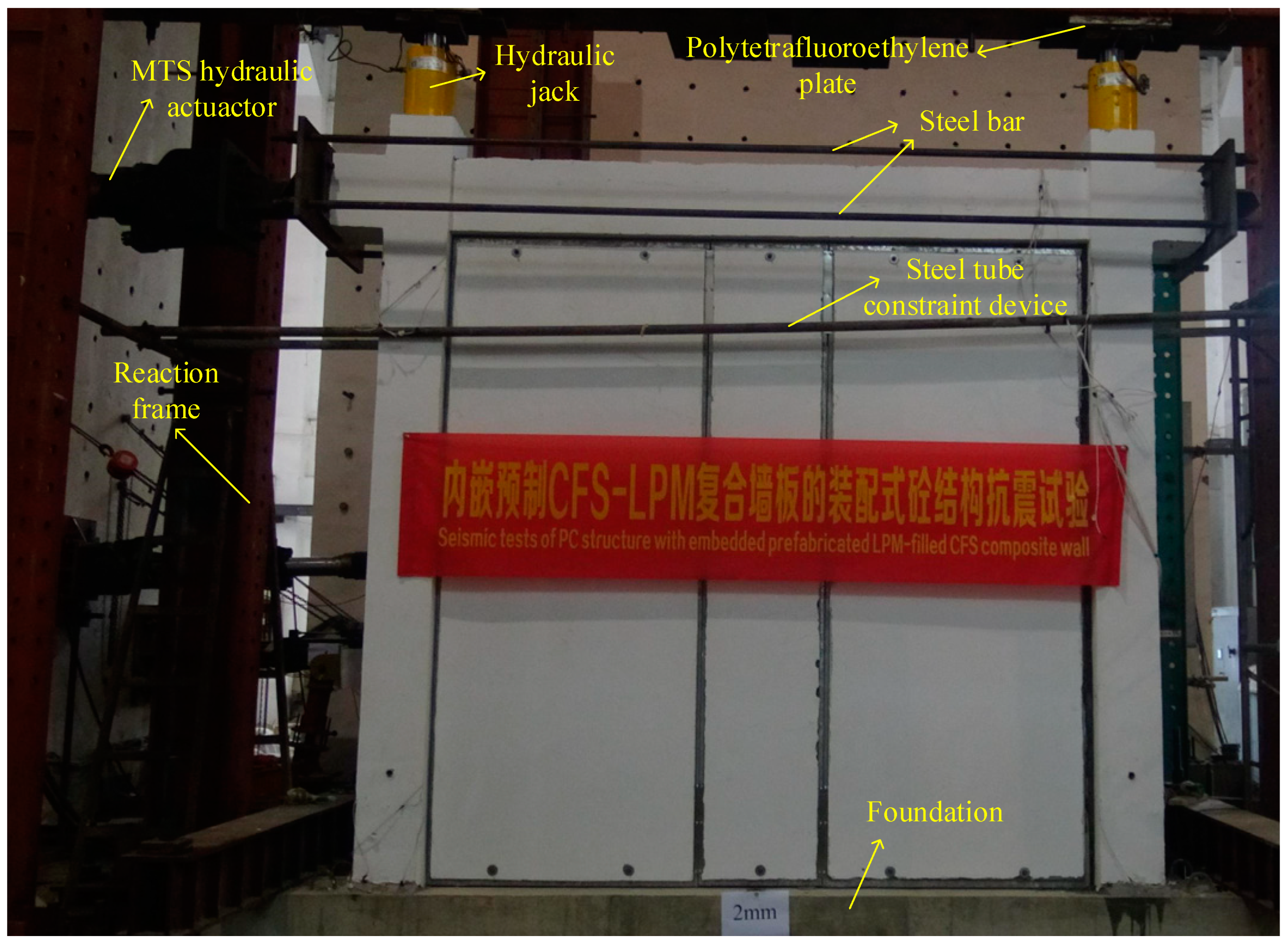
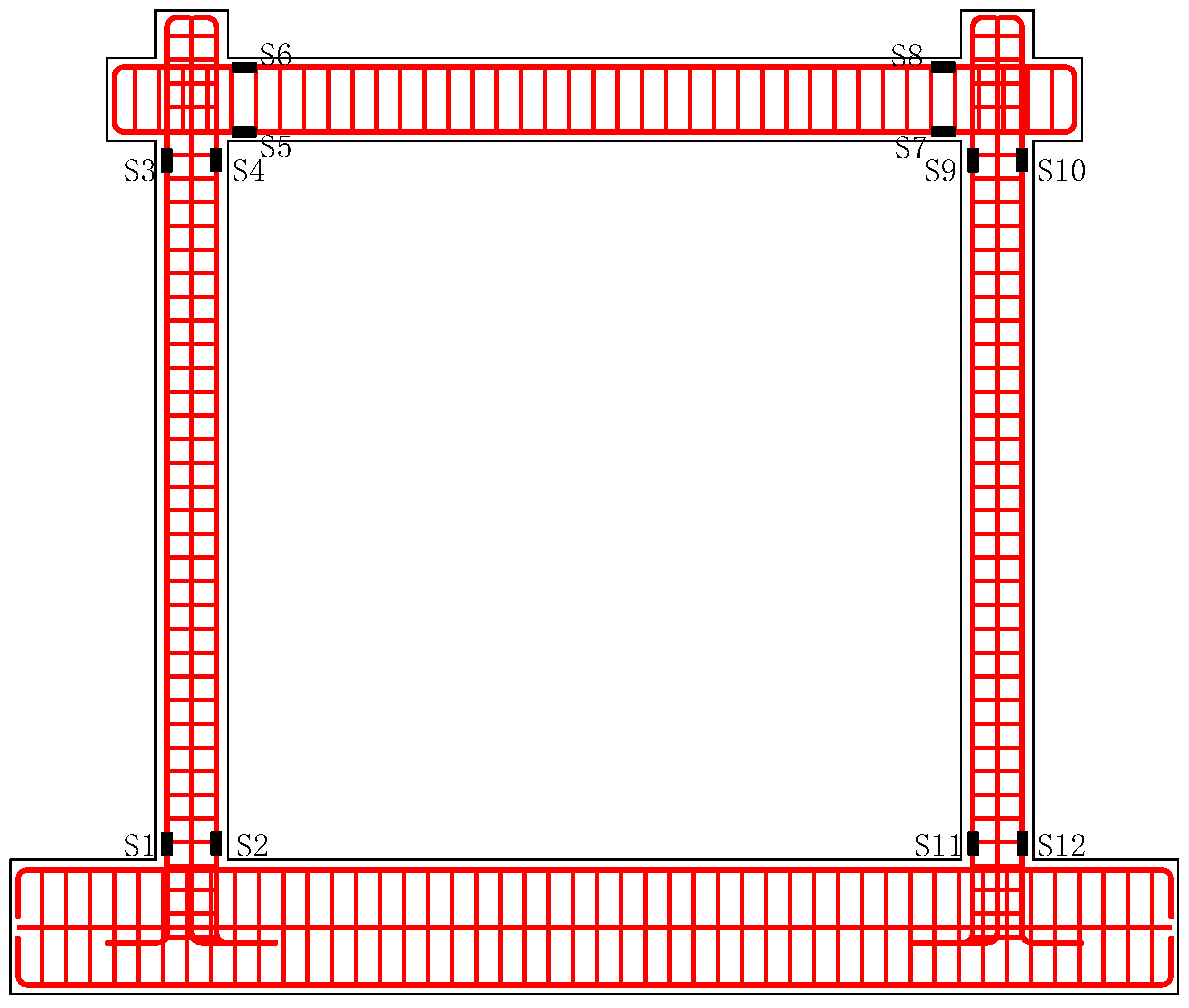
2.3. Test Setup and Measurements
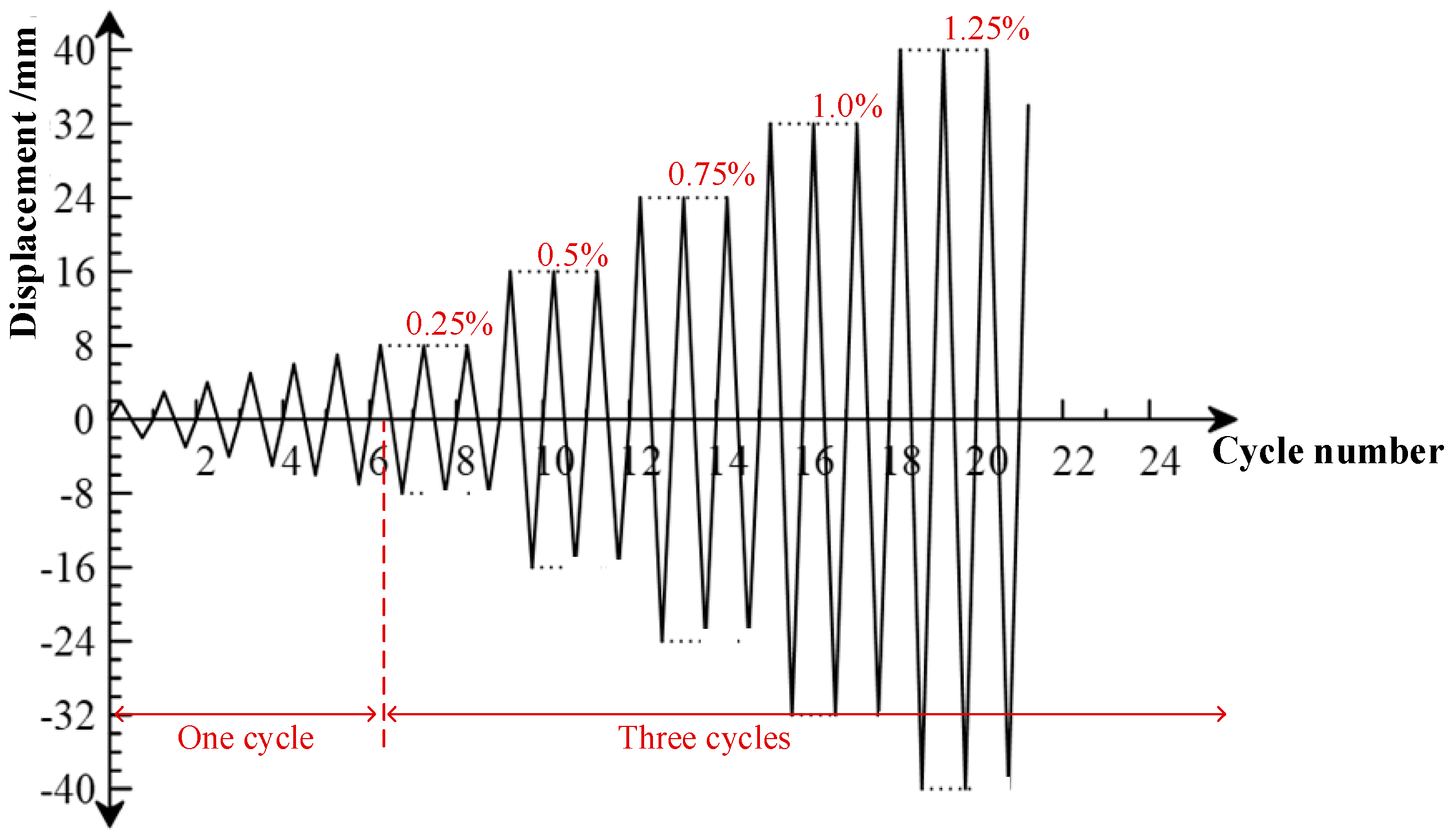
2.4. Loading Protocol
3. Experimental Results and Discussions
3.1. Failure Modes
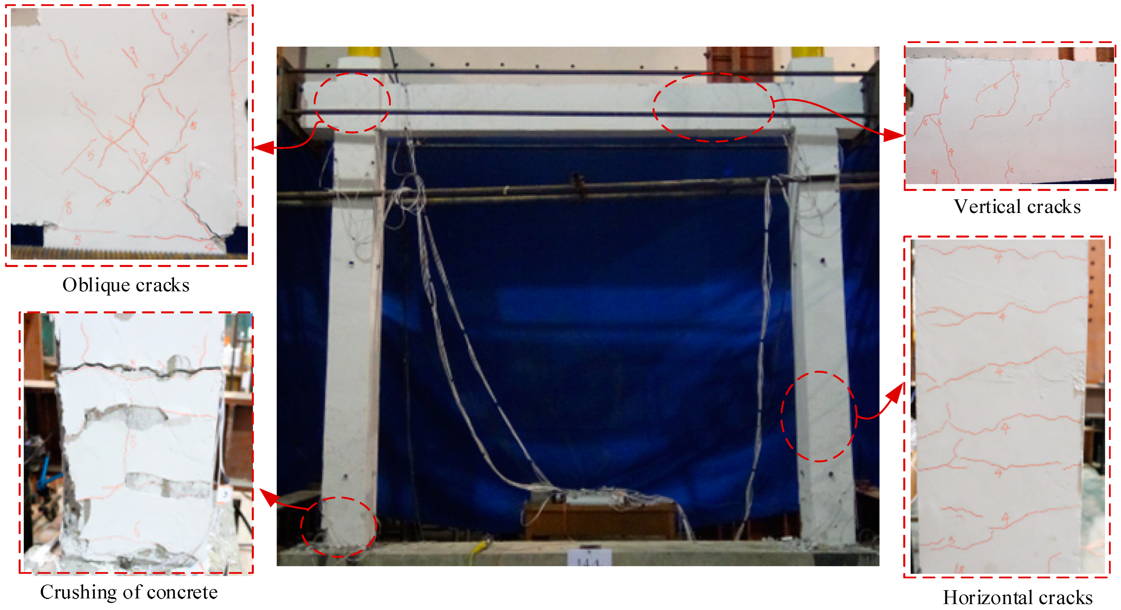
3.1.1. Specimen PCF
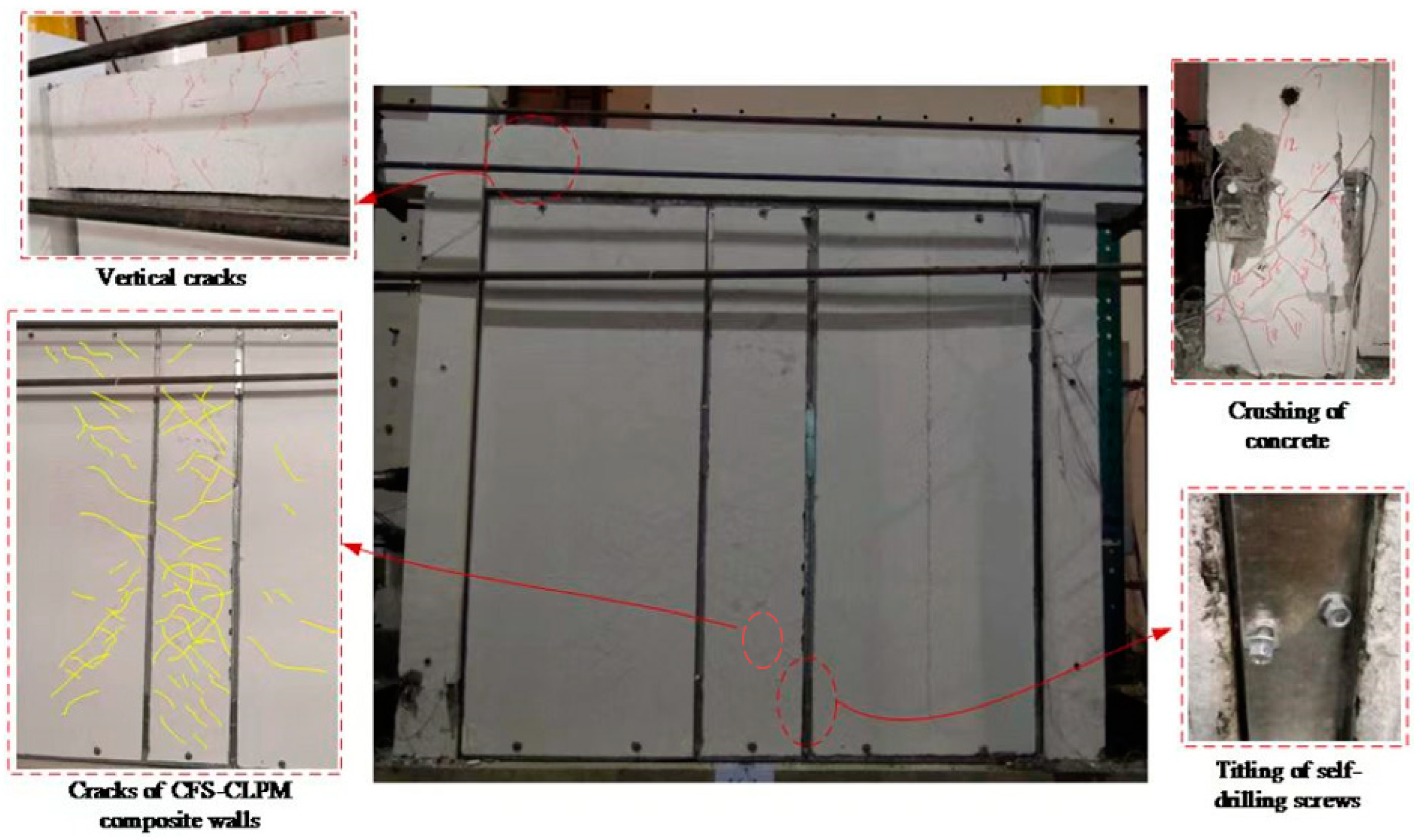
3.1.2. Specimen PCFW
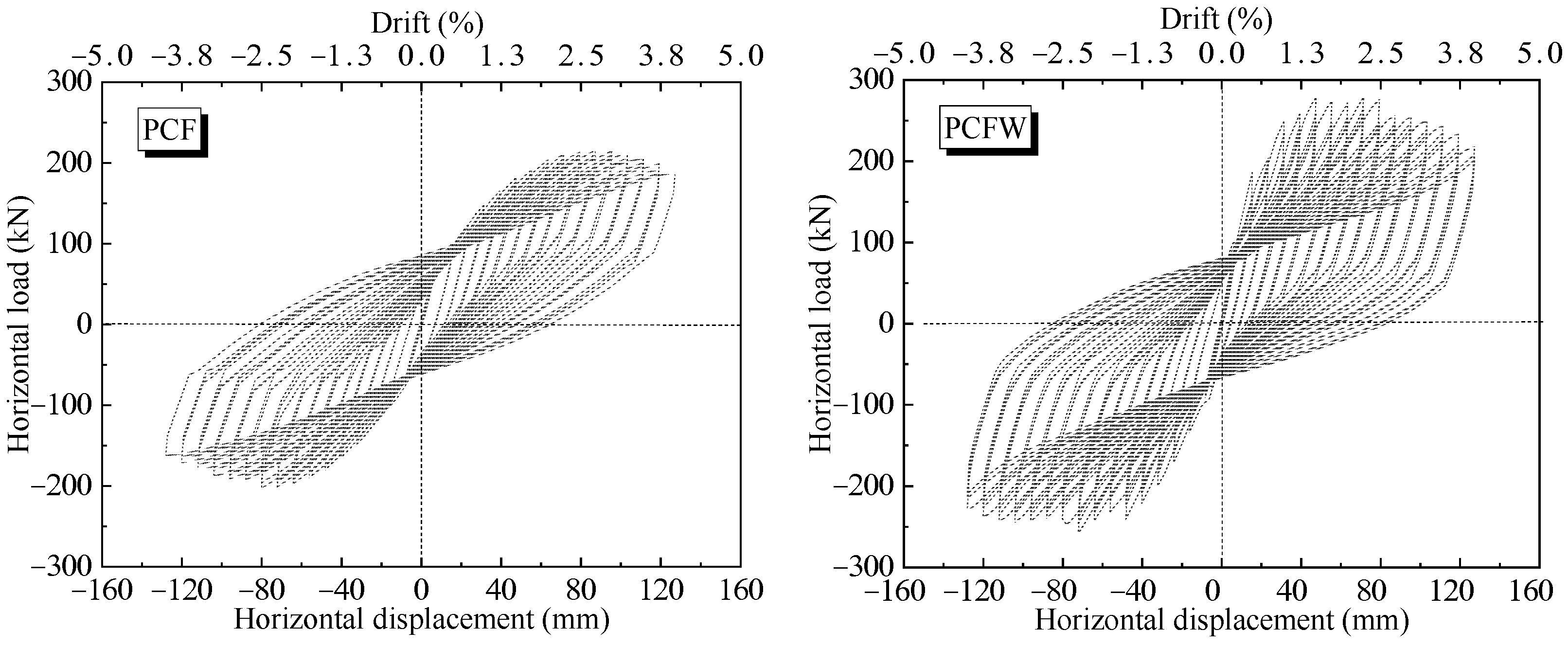
3.2. Hysteretic Response
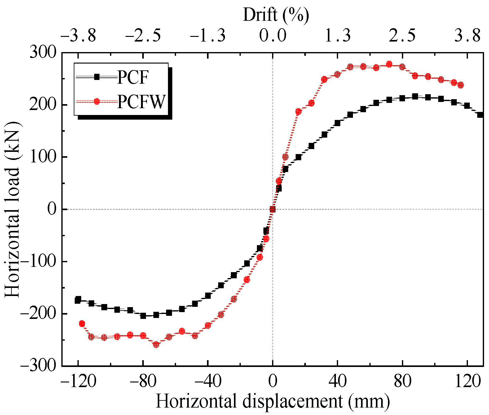
3.3. Feature Values and Ductility
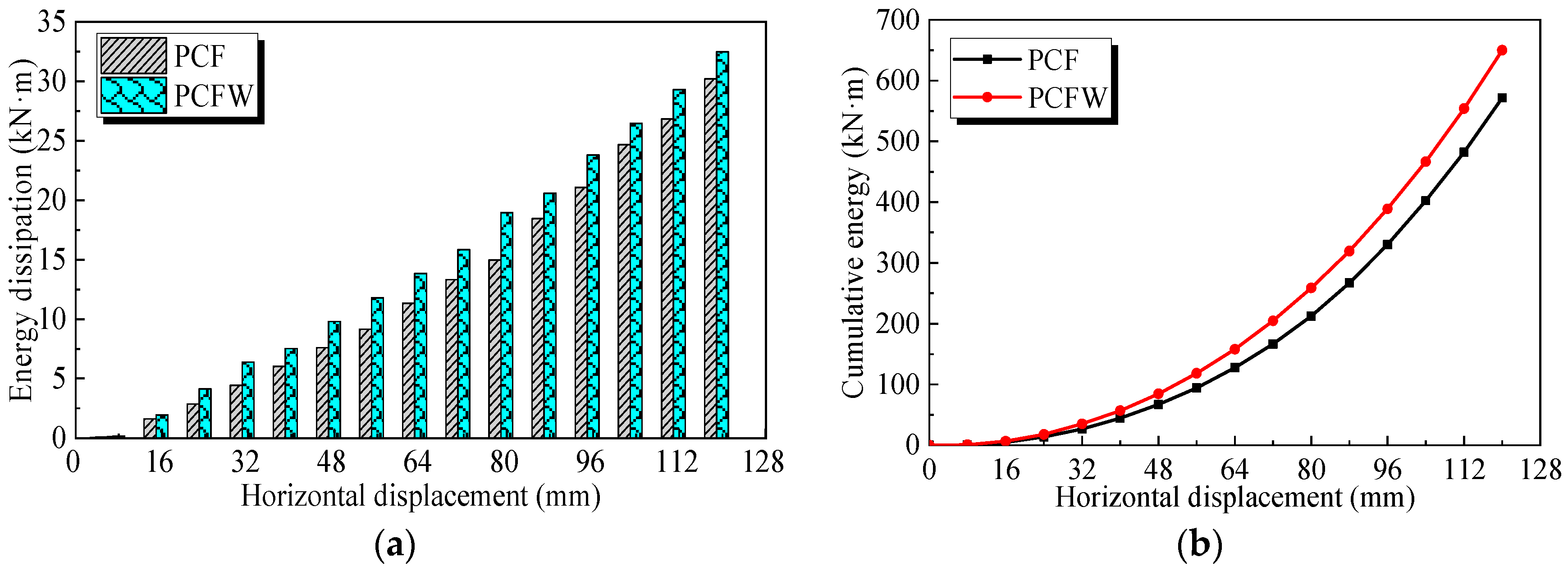
3.4. Energy Dissipation
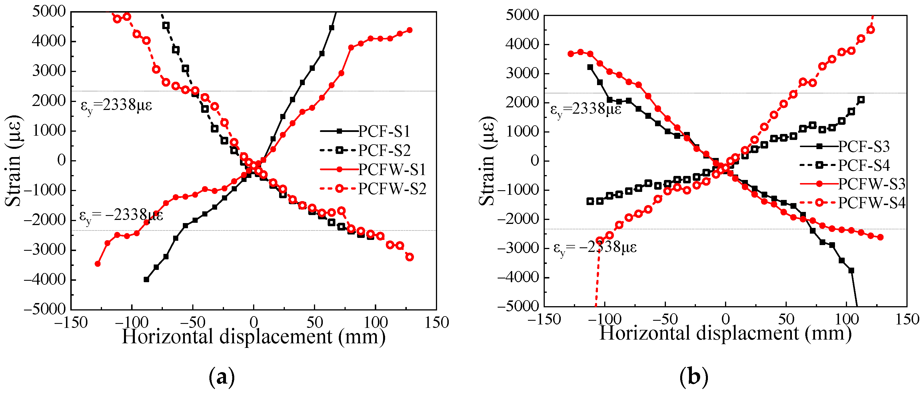
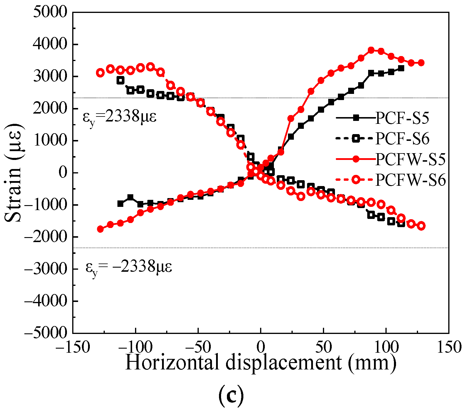
3.5. Strain Analyses
4. Numerical Analyses
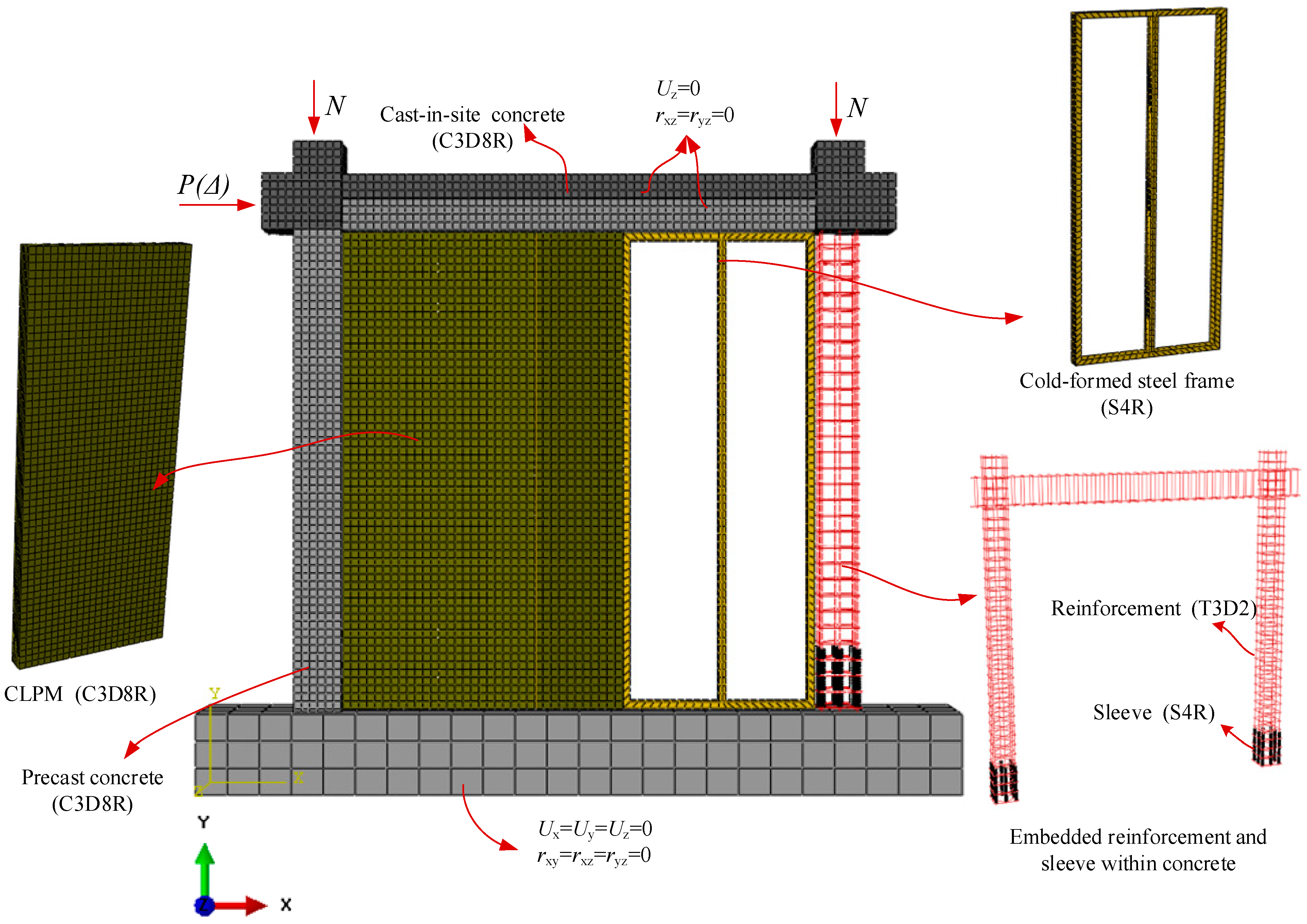
4.1. Model Characteristics
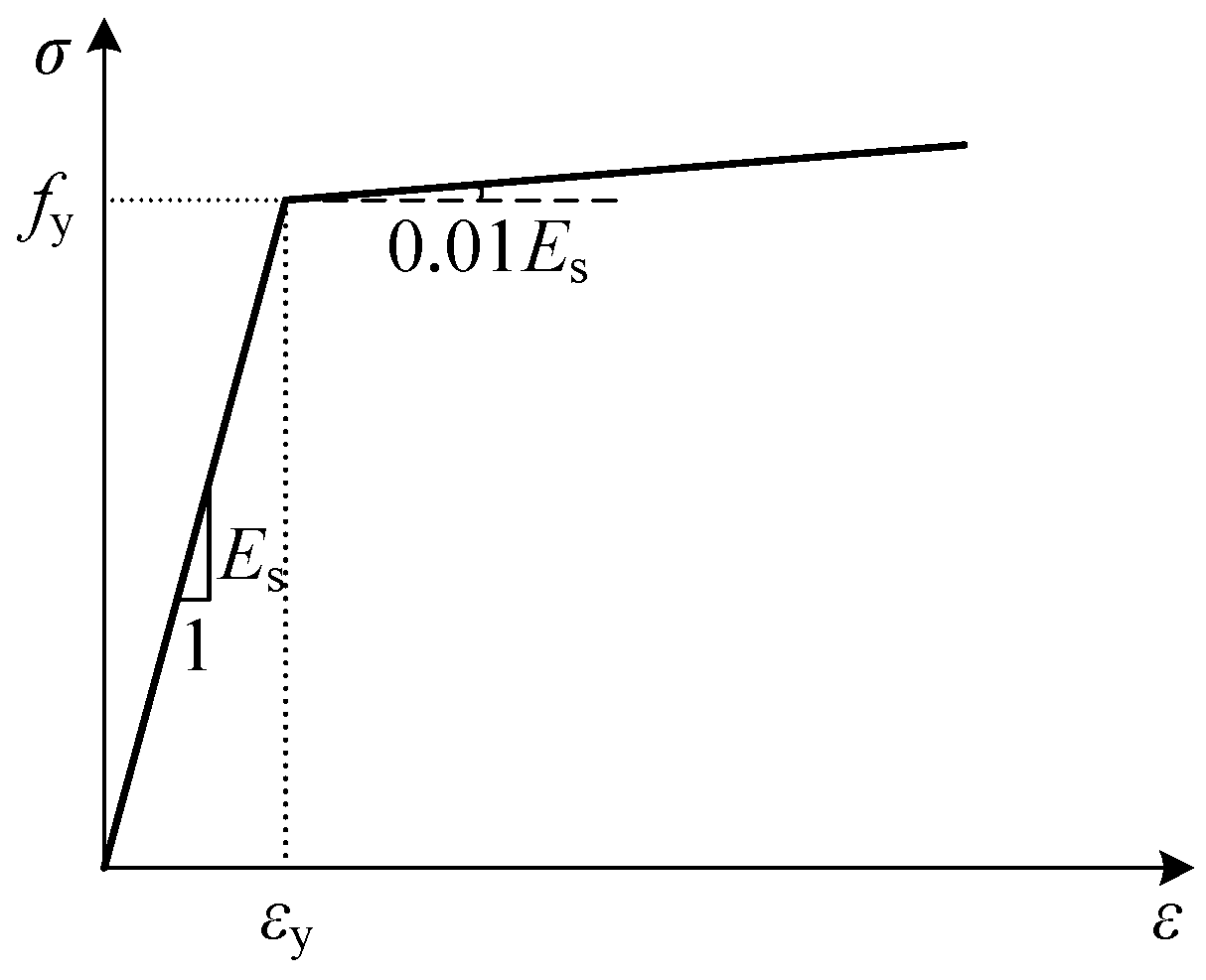
4.1.1. Material Laws
4.1.2. Element Types and Cell Meshing
4.1.3. Interaction and Boundary Conditions
4.2. Model Validation and Analyses
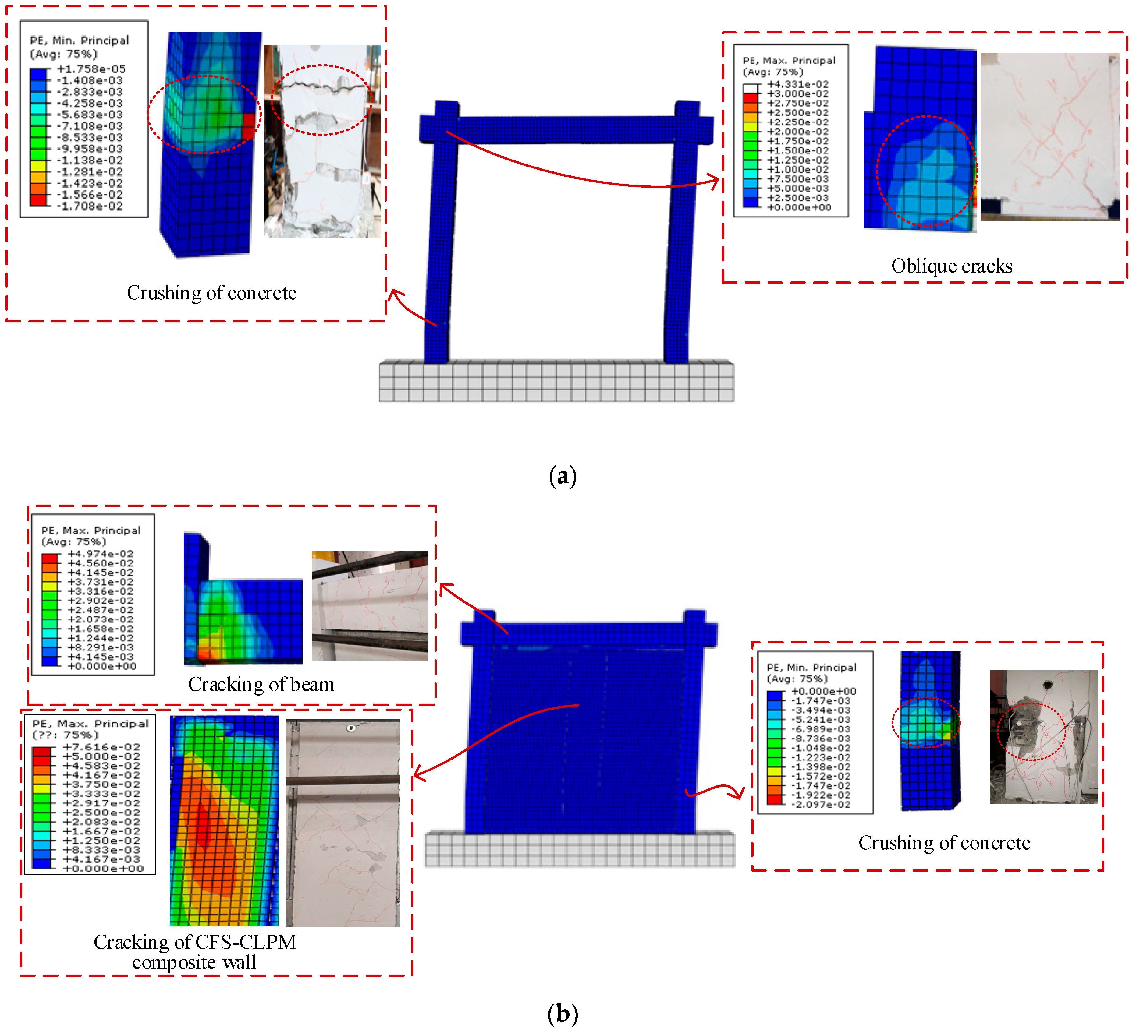
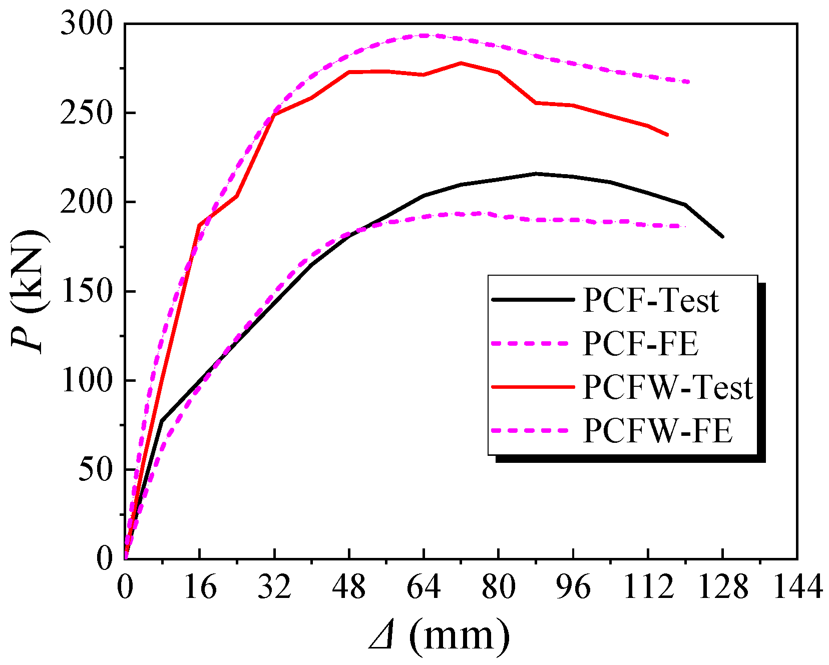
4.2.1. Model Validation
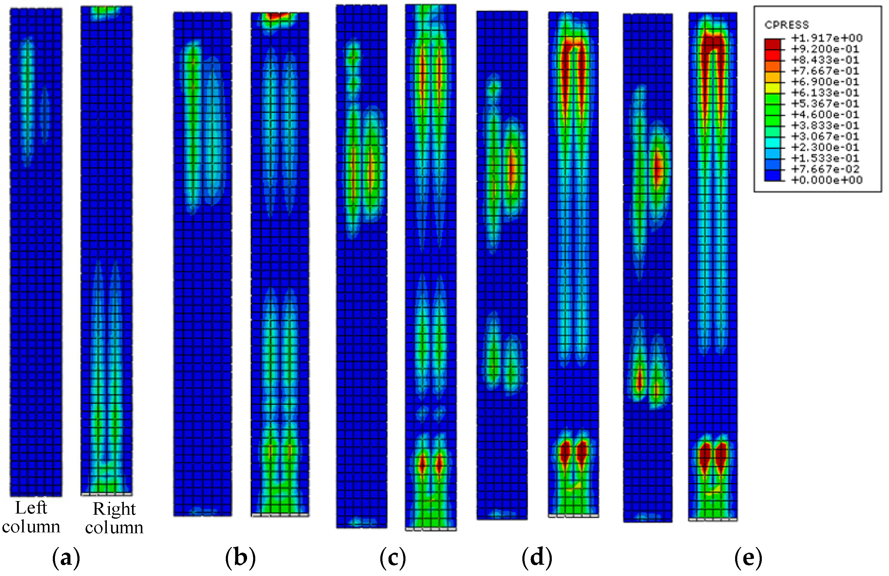
4.2.2. Contact Stress Distribution
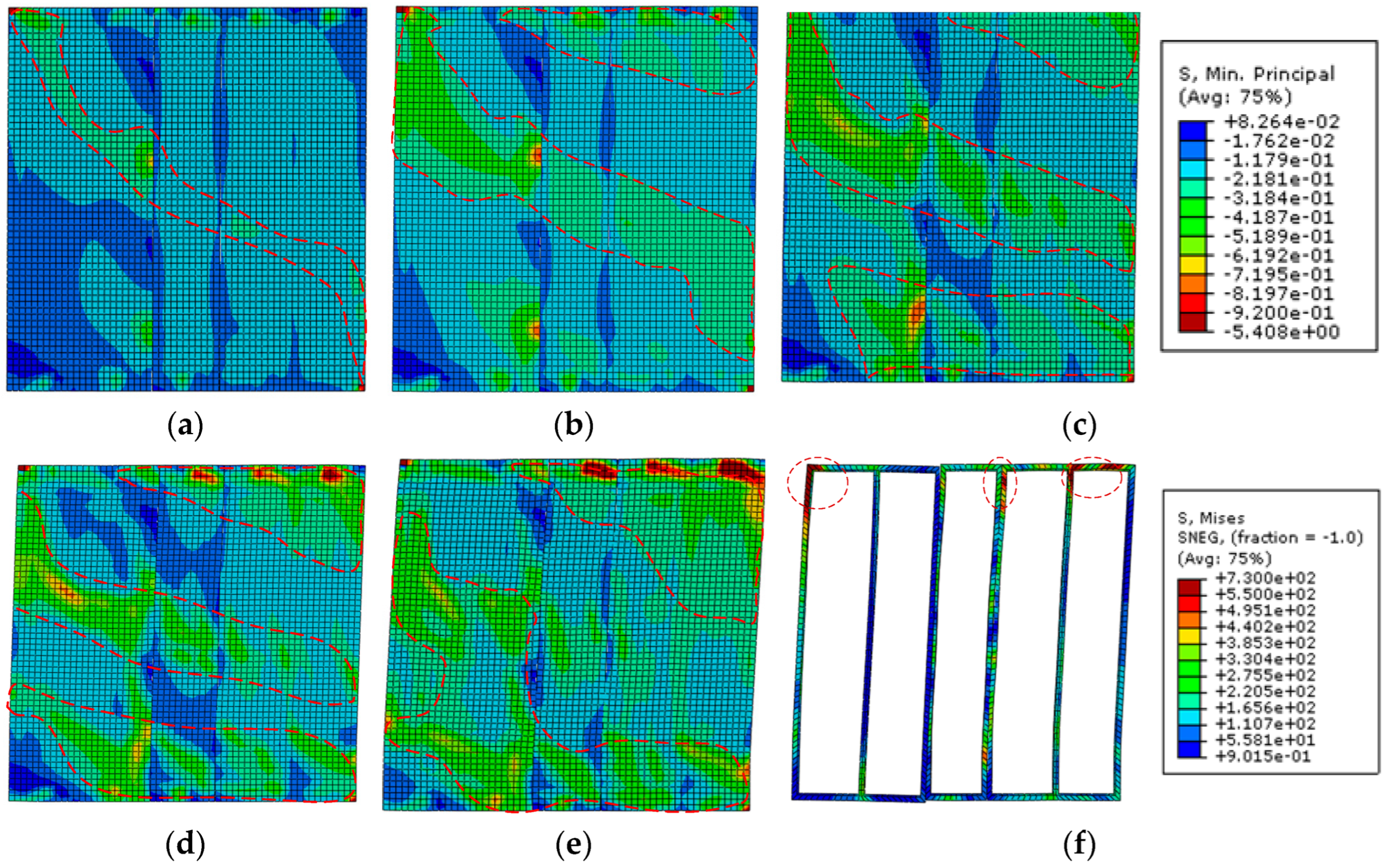
4.2.3. Analyses of the CFS-CLPM Composite Walls
4.3. Parametric Analyses
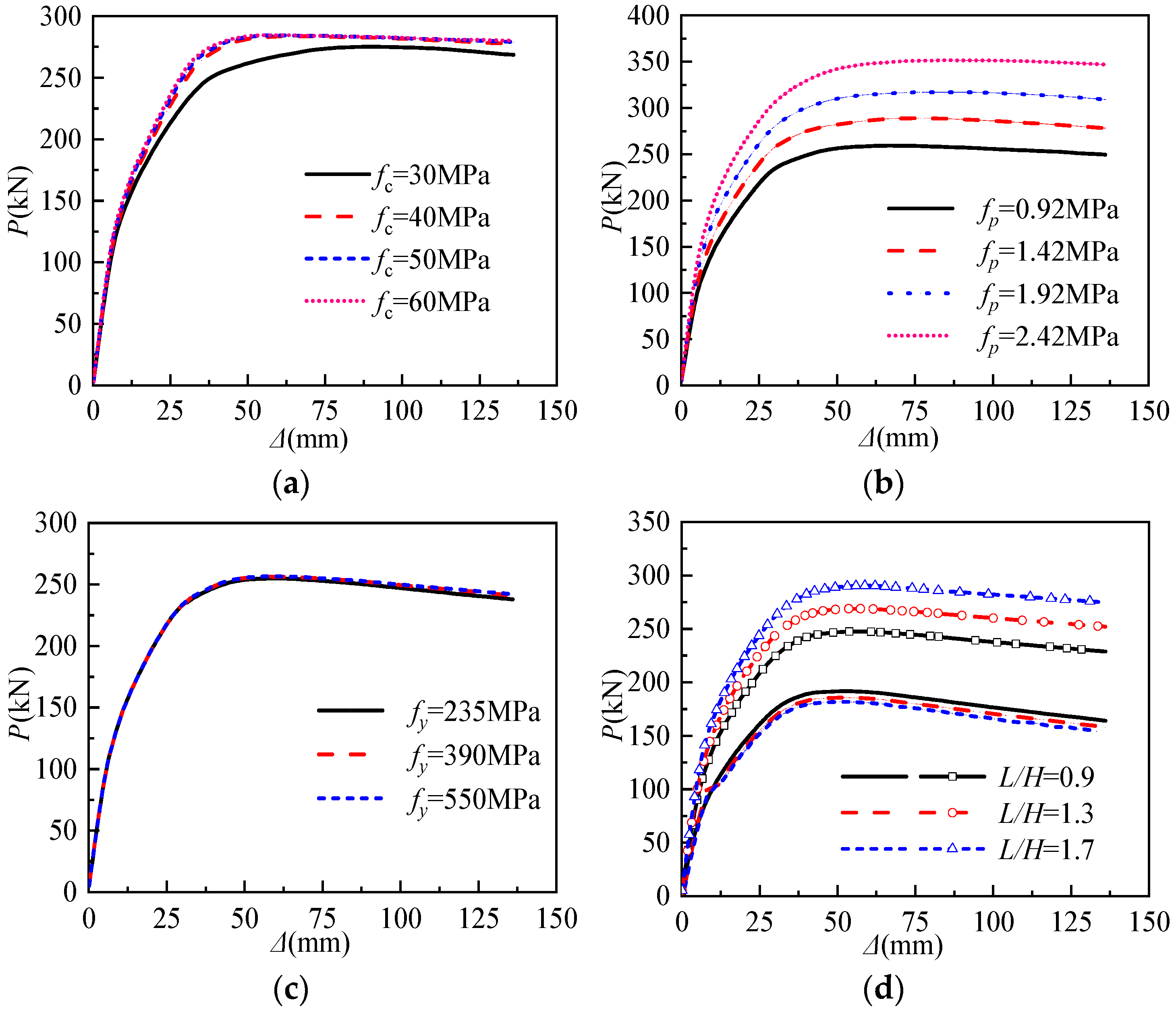
4.3.1. Compressive Strength of Concrete (fc)
4.3.2. Compressive Strength of CLPM (fp)
4.3.3. Strength of Cold-Formed Steel (fy)
4.3.4. Span to Height Ratio (L/H)
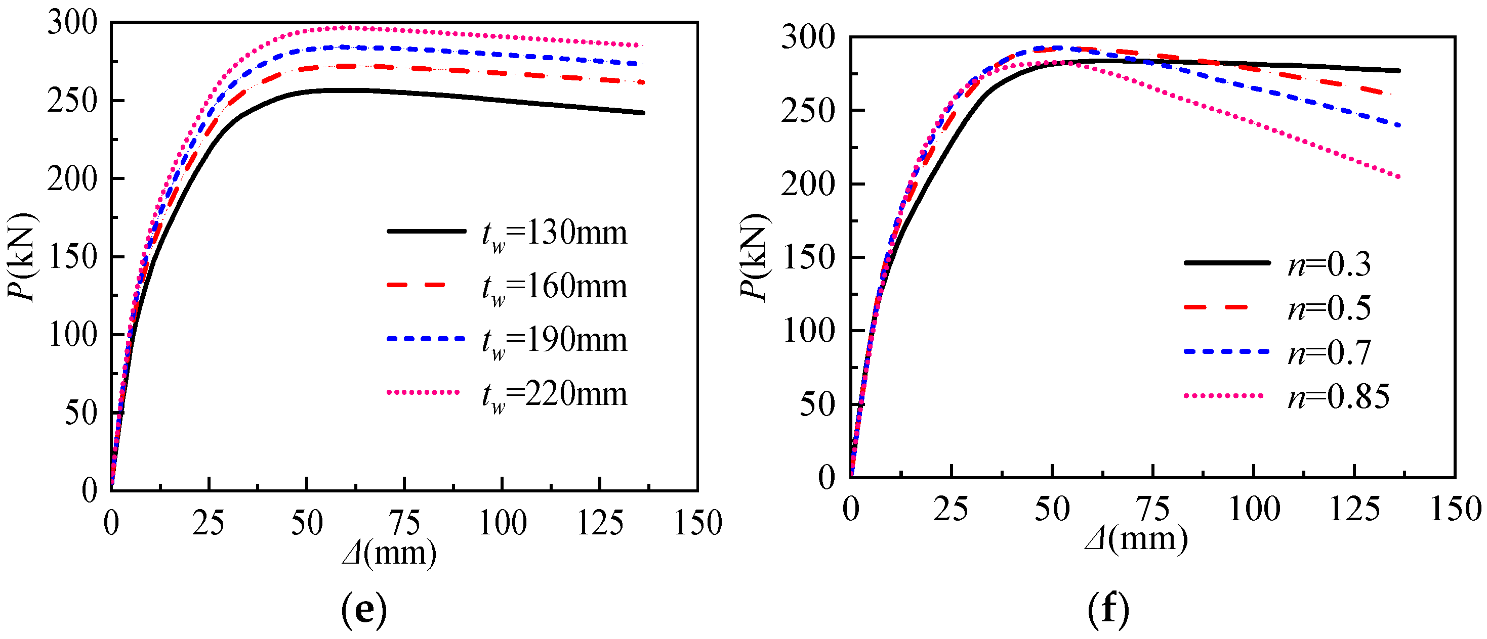
4.3.5. Thickness of CFS-CLPM Composite Walls (tw)
4.3.6. Axial Load Ratio (n)
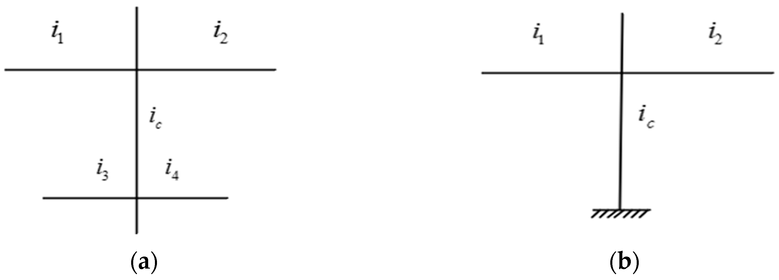
5. Prediction of the Elastic Stiffness
6. Conclusions
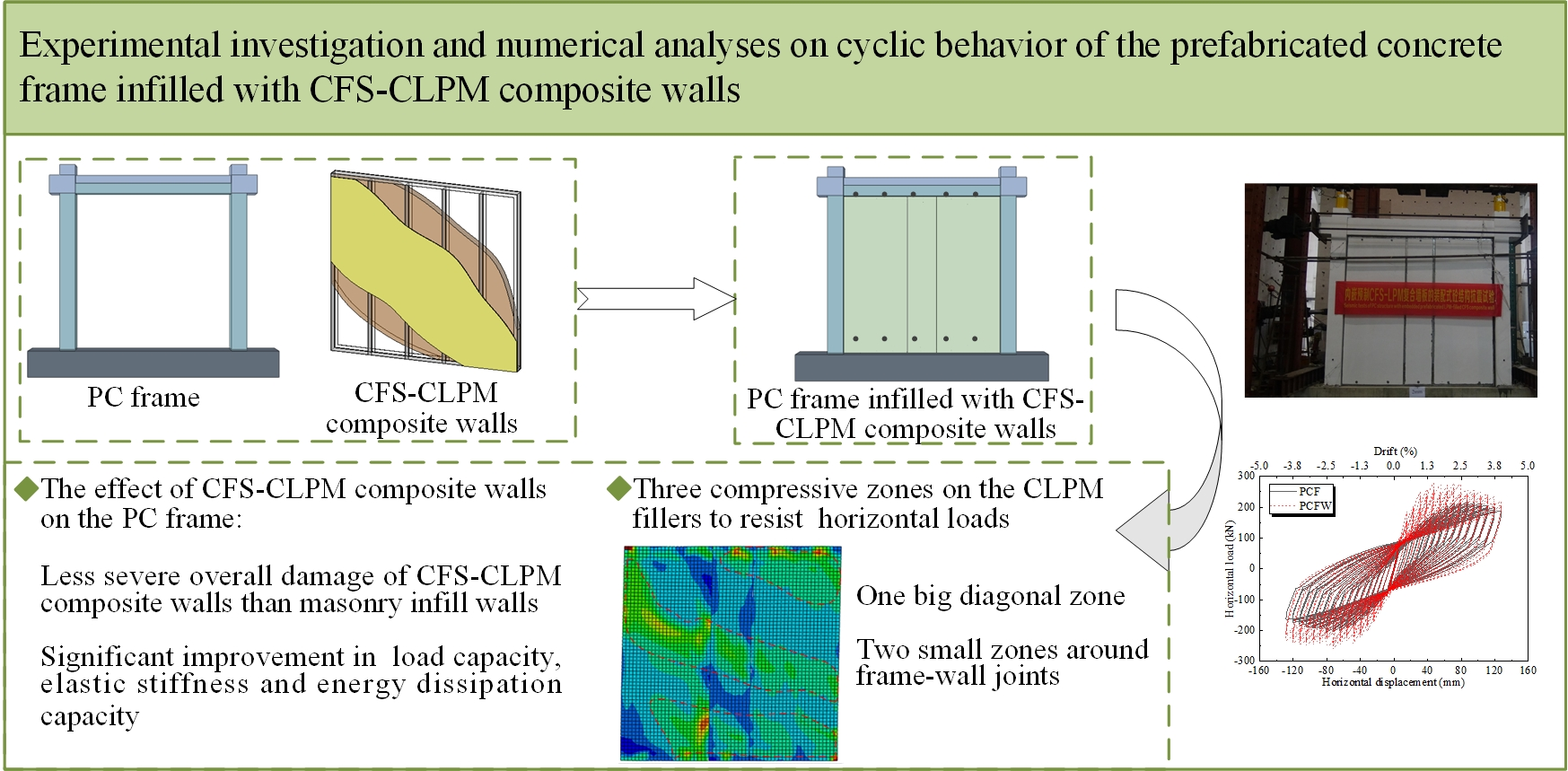
- The failure modes of the PC frame infilled with CFS-CLPM composite walls were characterized by cracks on the PC frame, diagonal cracks on the CFS-CLPM composite walls, titling of self-drilling screws, and crushing of the columns. The CFS-CLPM composite walls remained quite intact and the proposed wall-frame joints could restrain out-of-plane movements of the walls even at failure.
- The CFS-CLPM composite walls can significantly improve the lateral behavior of the PC frame structure. Compared with the bare frame, the lateral load capacity and elastic stiffness of the infilled frame were respectively 24.9~31.6% and 34.1~38.4% higher, respectively. Moreover, the energy dissipation capacity of the infilled frame structure increased by 14%. Despite a slight reduction in the ductility of the infilled PC frame structure owing to the infill-frame interaction, its failure drift can meet the elastic-plastic drift requirement of 2%.
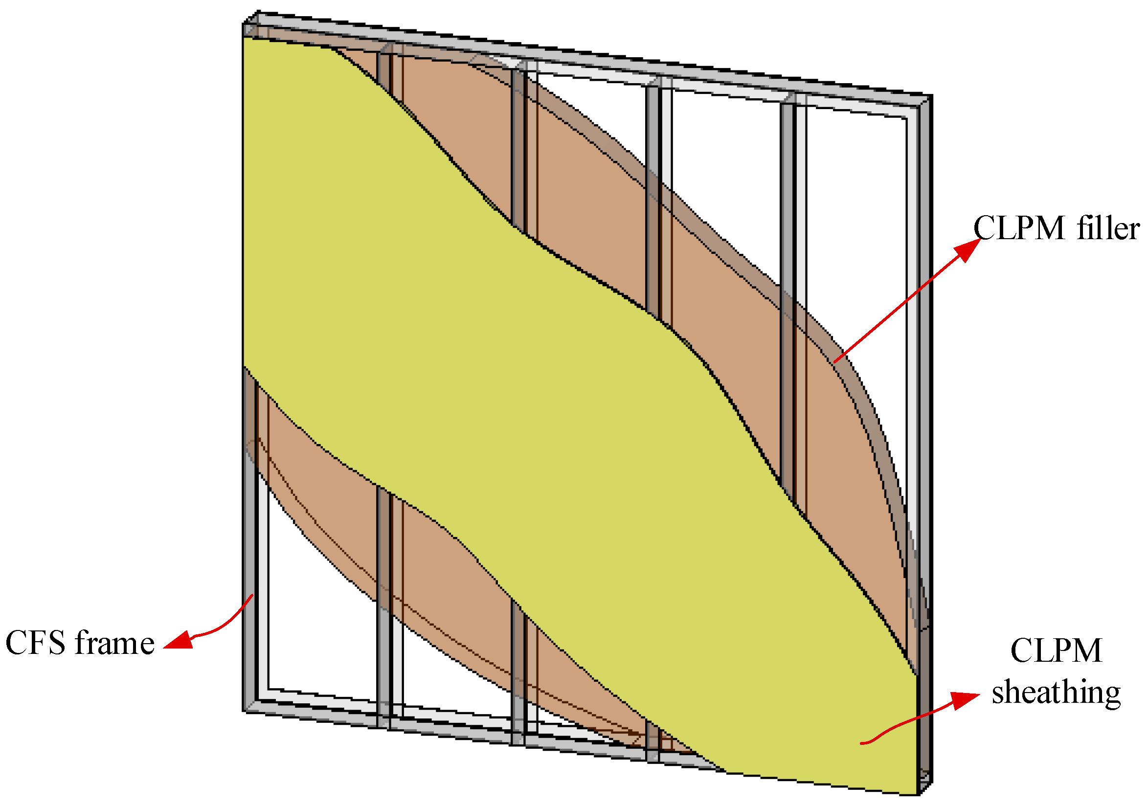
- The numerical analyses of the infilled PC frame structure revealed that CLPM fillers were the significant lateral resistance elements of the CFS-CLPM composite walls. Three compressive zones were formed on the CLPM fillers, because the horizontal shear force was transferred from the PC frame to CFS-CLPM composite walls through the frame-wall joints between the composite wall and PC beam, and the compression between the composite wall and the PC column.
- Parametric analyses of the PC frame infill with CFS-CLPM composite walls indicated that the strength of CLPM, the span-to-height ratio, and the thickness of CFS-CLPM composite walls significantly affected the lateral capacity of the structure, while the strength of concrete, the strength of cold-formed steel and the axial load ratio affected slightly.
- A formula considering the lateral resistance of the CFS-CLPM composite walls was proposed to predict the elastic lateral stiffness of the PC frame infilled with CFS-CLPM composite walls and the comparisons among prediction and test as well as simulation results demonstrated that the formula was reliable.
Author Contributions
Funding
Institutional Review Board Statement
Informed Consent Statement
Data Availability Statement
Conflicts of Interest
References
- Badr, A.R.; Elanwar, H.H.; Mourad, S.A. Numerical and experimental investigation on cold-formed walls sheathed by fiber cement board. J. Constr. Steel Res. 2019, 158, 366–380. [Google Scholar] [CrossRef]
- Macillo, V.; Fiorino, L.; Landolfo, R. Seismic response of CFS shear walls sheathed with nailed gypsum panels: Experimental tests. Thin-Walled Struct. 2017, 120, 161–171. [Google Scholar] [CrossRef]
- Ali, E.; Althoey, F. Numerical investigation on blast response of cold-formed steel framing protected with functionally graded composite material. Buildings 2022, 12, 118. [Google Scholar] [CrossRef]
- Xu, Z.F.; Chen, Z.F.; Osman, B.H.; Yang, S.H. Seismic performance of high-strength lightweight foamed concrete-filled cold-formed steel shear walls. J. Constr. Steel Res. 2018, 143, 148–161. [Google Scholar] [CrossRef]
- Ananthi, G.B.G.; Roy, K.; Lim, J.B.P. Experimental and numerical study of an innovative 4-channels cold-formed steel built-up column under axial compression. Steel Compos. Struct. 2022, 42, 513–538. [Google Scholar]
- Ananthi, G.B.G. A study on cold-formed steel compound angle section subjected to axial compression. KSCE J. Civ. Eng. 2018, 22, 1803–1815. [Google Scholar] [CrossRef]
- Mousavi, S.A.; Zahrai, S.M.; Bahrami-Rad, A. Quasi-static cyclic tests on super-lightweight EPS concrete shear walls. Eng. Struct. 2014, 65, 62–75. [Google Scholar] [CrossRef]
- Shannag, M.J. Characteristics of lightweight concrete containing mineral admixtures. Constr. Build. Mater. 2011, 25, 658–662. [Google Scholar] [CrossRef]
- Mydin, M.A.O.; Wang, Y.C. Structural performance of lightweight steel-foamed concrete-steel composite walling system under compression. Thin-Walled Struct. 2011, 49, 66–76. [Google Scholar] [CrossRef]
- Yin, C.; Zhou, L.; Zou, Q.Y.; Xu, Y.F. Effect of filling phosphorgypsum on the axial compression behavior of cold-formed thin-walled steel walls. Buildings 2022, 12, 1325. [Google Scholar] [CrossRef]
- Wu, H.H.; Sui, L.; Wang, J.Q.; Zhou, T.H. Cycle performance tests and numerical modeling of infilled CFS shear wall. J. Constr. Steel Res. 2020, 168, 106010. [Google Scholar] [CrossRef]
- Wang, W.Q.; Wang, J.F.; Zhao, P.; Ja, L.L.; Pan, G.D. Axial compressive experiments and structural behaviour estimation of CFS composite walls sprayed with LPM. J. Build. Eng. 2020, 30, 101305. [Google Scholar] [CrossRef]
- Wang, W.Q.; Wang, J.F.; Guo, L.; Liu, Y.; Zhang, R. Cyclic performance tests and numerical analysis of prefabricated CFS shear walls filled with lightweight EPS mortars. Eng. Struct. 2021, 243, 112554. [Google Scholar] [CrossRef]
- Wang, J.Q.; Zhou, T.H.; Wu, H.H.; Guan, Y.; Zhang, L. Cyclic performance of steel frame fabricated with cold-formed steel composite wall structure. Eng. Struct. 2022, 270, 114892. [Google Scholar] [CrossRef]
- Wang, F.L.; Yang, J.; Wang, X.; Azim, I. Study on progressive collapse behaviour of steel-framed substructures with sheathed CFS stud infill walls. J. Build. Eng. 2021, 42, 102720. [Google Scholar] [CrossRef]
- Kildashti, K.; Samali, B.J.; Mortazavi, M.; Ronagh, H.; Sharafi, P. Seismic collapse assessment of a hybrid cold-formed hot-rolled steel building. J. Constr. Steel Res. 2019, 155, 504–516. [Google Scholar] [CrossRef]
- JGJ 355-2015; Technical Specification for Grout Sleeve Splicing of Rebars. China Architecture & Building Press: Beijing, China, 2015.
- GB/T 51231-2016; Technical Standard for Assembled Buildings with Concrete Structure. China Architecture & Building Press: Beijing, China, 2017.
- 19. JGJ 1-2014; Technical Specification for Precast Concrete Structures. China Architecture & Building Press: Beijing, China, 2014.
- GB/T 50081-2002; Standard for Test Method of Mechanical Properties on Ordinary Concrete. China Architecture & Building Press: Beijing, China, 2003.
- JG/T 266-2011; Foamed Concrete. Architecture & Industry Press of China: Beijing, China, 2011.
- GB/T 228.1-2010; Metallic Materials-Tensile Testing-Part 1: Method of Test at Room Temperature. General Administration of Quality Supervision, Inspection of PR China: Beijing, China, 2012.
- Dautaj, A.D.; Kadiri, Q.; Kabash, N. Experimental study on the contribution of masonry infill in the behavior of RC frame under seismic loading. Eng. Struct. 2018, 165, 27–37. [Google Scholar] [CrossRef]
- Dabiri, H.; Kaviani, A.; Kheyroddin, A. Influence of reinforcement on the performance of non-seismically detailed RC beam-column joints. J. Build. Eng. 2020, 31, 101333. [Google Scholar] [CrossRef]
- GB 50011-2010; Code for Seismic Design of Buildings. China Architecture & Building Press: Beijing, China, 2010.
- Popovics, S. A numerical approach to the complete stress-strain curve of concrete. Cem. Concr. Res. 1973, 3, 583–599. [Google Scholar] [CrossRef]
- Cui, C.C.; Huang, Q.; Li, D.B.; Quan, C.R.; Li, H.C. Stress–strain relationship in axial compression for EPS concrete. Constr. Build. Mater. 2016, 105, 377–383. [Google Scholar] [CrossRef]
- Lai, B.L.; Yang, L.F.; Xiong, M.X. Numerical simulation and data-driven analysis on the flexural performance of steel reinforced concrete composite members. Eng. Struct. 2021, 247, 113200. [Google Scholar] [CrossRef]
- Mutō, K. Aseismic Design Analysis of Buildings; Maruzen Company, Ltd.: Tokyo, Japan, 1974. [Google Scholar]


| Cement (kg/m3) | Fly Ash (kg/m3) | Expansive Agent (kg/m3) | Water-Reducing Agent (kg/m3) | EPS (kg/m3) | Water (kg/m3) |
|---|---|---|---|---|---|
| 300 | 65 | 125 | 2 | 0.6 | 225 |
| Steel Item | Thickness/ Diameter (mm) | Yield Strength (MPa) | Ultimate Strength (MPa) | Yield Strain | Elastic Modulus (MPa) |
|---|---|---|---|---|---|
| reinforcement | 18 | 491 | 663 | 2338 × 10−6 | 2.1 × 10⁵ |
| reinforcement | 8 | 476 | 768 | 2268 × 10−6 | 2.1 × 10⁵ |
| C-section steel | 0.9 | 696 | 1006 | 3314 × 10−6 | 2.05 × 10⁵ |
| C-section steel | 1.2 | 695 | 1017 | 3310 × 10−6 | 2.06 × 10⁵ |
| Specimen | Δy/mm | Py/kN | Δm/mm | Pm/kN | Δu/mm | Pf/kN | Elastic Stiffness kN/mm | μΔ |
|---|---|---|---|---|---|---|---|---|
| PCF (+) | 40.9 | 166.2 | 88.0 | 212.58 | 127.3 | 180.7 | 10.22 | 3.26 |
| PCF (−) | 35.4 | 154.2 | 80.4 | 206.62 | 120.5 | 175.6 | 10.50 | |
| PCFW (+) | 37.7 | 248.3 | 72.0 | 279.8 | 116.1 | 237.8 | 14.53 | 3.16 |
| PCFW (−) | 36.5 | 223.2 | 72.0 | 258.0 | 117.7 | 219.3 | 14.87 |
| Specimen | Test | Simulation | Ke,s/Ke,t | Pm,s/Pm,t | ||
|---|---|---|---|---|---|---|
| Ke,t (kN/mm) | Pm,t (kN) | Ke,s (kN/mm) | Pm,s (kN) | |||
| PCF (+) | 10.22 | 212.58 | 8.53 | 193.70 | 0.83 | 0.91 |
| PCFW (+) | 14.53 | 279.80 | 15.34 | 293.31 | 1.06 | 1.05 |
| FE-Models | Material | Geometry | Load Ratio | |||
|---|---|---|---|---|---|---|
| fc/MPa | fp/MPa | fy/MPa | L/H | tw/mm | n | |
| FE-SS | 26.8 | 0.92 | 550 | 1.1 | 130 | 0.3 |
| FE-11 | 20.1 | 0.92 | 550 | 1.1 | 130 | 0.3 |
| FE-12 | 33.5 | 0.92 | 550 | 1.1 | 130 | 0.3 |
| FE-13 | 40.2 | 0.92 | 550 | 1.1 | 130 | 0.3 |
| FE-21 | 26.8 | 1.42 | 550 | 1.1 | 130 | 0.3 |
| FE-22 | 26.8 | 1.92 | 550 | 1.1 | 130 | 0.3 |
| FE-23 | 26.8 | 2.42 | 550 | 1.1 | 130 | 0.3 |
| FE-31 | 26.8 | 0.92 | 235 | 1.1 | 130 | 0.3 |
| FE-32 | 26.8 | 0.92 | 390 | 1.1 | 130 | 0.3 |
| FE-41 | 26.8 | 0.92 | 550 | 0.9 | 130 | 0.3 |
| FE-42 | 26.8 | 0.92 | 550 | 1.3 | 130 | 0.3 |
| FE-43 | 26.8 | 0.92 | 550 | 1.7 | 130 | 0.3 |
| FE-51 | 26.8 | 0.92 | 550 | 1.1 | 160 | 0.3 |
| FE-52 | 26.8 | 0.92 | 550 | 1.1 | 190 | 0.3 |
| FE-53 | 26.8 | 0.92 | 550 | 1.1 | 220 | 0.3 |
| FE-61 | 26.8 | 0.92 | 550 | 1.1 | 130 | 0.5 |
| FE-62 | 26.8 | 0.92 | 550 | 1.1 | 130 | 0.7 |
| FE-63 | 26.8 | 0.92 | 550 | 1.1 | 130 | 0.85 |
| Samples | Kt (kN/mm) | Kp (kN/mm) | Kp /Kt |
|---|---|---|---|
| PCF | 10.22 | 10.347 | 1.012 |
| PCFW | 14.53 | 14.878 | 1.023 |
| PE-SS | 14.967 | 14.907 | 0.996 |
| FE-21 | 16.604 | 16.375 | 0.986 |
| FE-22 | 18.358 | 17.836 | 0.972 |
| FE-23 | 20.14 | 19.297 | 0.958 |
| FE-41 | 14.21 | 13.192 | 0.921 |
| FE-42 | 15.67 | 15.73 | 1.004 |
| FE-43 | 17.54 | 19.482 | 1.111 |
| FE-51 | 15.867 | 15.967 | 1.006 |
| FE-52 | 16.565 | 17.021 | 1.028 |
| FE-53 | 17.269 | 18.075 | 1.047 |
| Average | - | - | 1.005 |
| Coefficient of variation | - | - | 0.0021 |
Publisher’s Note: MDPI stays neutral with regard to jurisdictional claims in published maps and institutional affiliations. |
© 2022 by the authors. Licensee MDPI, Basel, Switzerland. This article is an open access article distributed under the terms and conditions of the Creative Commons Attribution (CC BY) license (https://creativecommons.org/licenses/by/4.0/).
Share and Cite
Hu, P.; Liu, Y.; Wang, J.; Wang, W.; Pan, G. Experimental Investigation and Numerical Analyses on Cyclic Behavior of the Prefabricated Concrete Frame Infilled with CFS-CLPM Composite Walls. Buildings 2022, 12, 1991. https://doi.org/10.3390/buildings12111991
Hu P, Liu Y, Wang J, Wang W, Pan G. Experimental Investigation and Numerical Analyses on Cyclic Behavior of the Prefabricated Concrete Frame Infilled with CFS-CLPM Composite Walls. Buildings. 2022; 12(11):1991. https://doi.org/10.3390/buildings12111991
Chicago/Turabian StyleHu, Peifang, Yong Liu, Jingfeng Wang, Wanqian Wang, and Guangdong Pan. 2022. "Experimental Investigation and Numerical Analyses on Cyclic Behavior of the Prefabricated Concrete Frame Infilled with CFS-CLPM Composite Walls" Buildings 12, no. 11: 1991. https://doi.org/10.3390/buildings12111991