
Analytical and Numerical Study on the Performance of the Curved Surface of a Circular Tunnel Reinforced with CFRP


Abstract
:1. Introduction
2. Analytical Study on the Stresses of the Curved Reinforced Interface
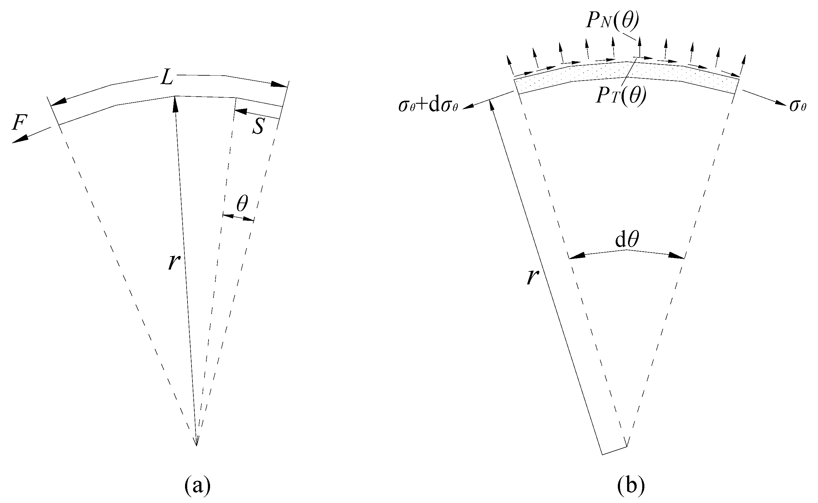
2.1. Analytical Model
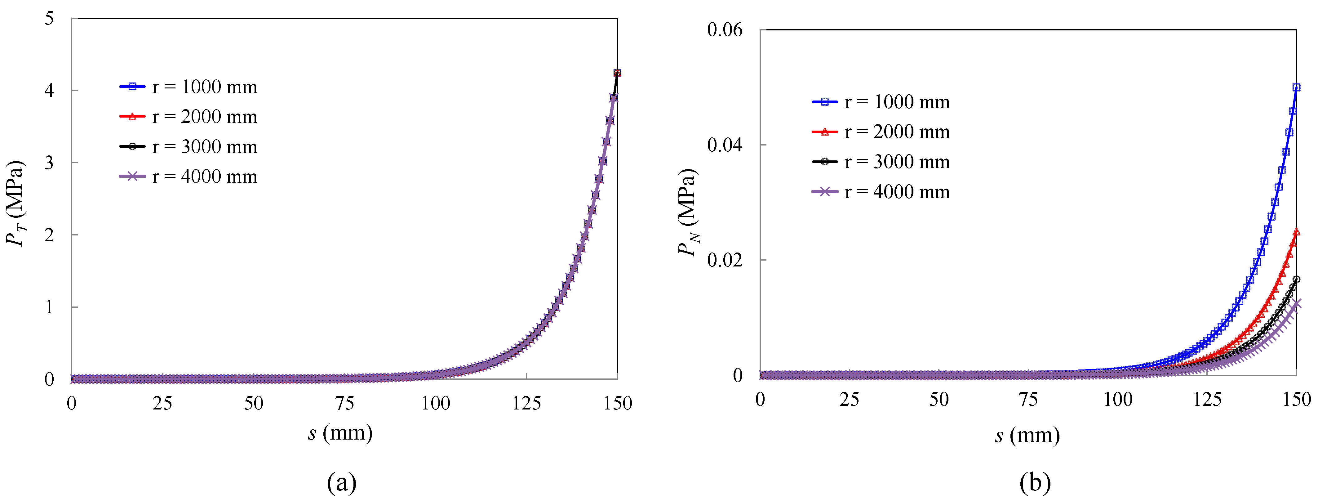
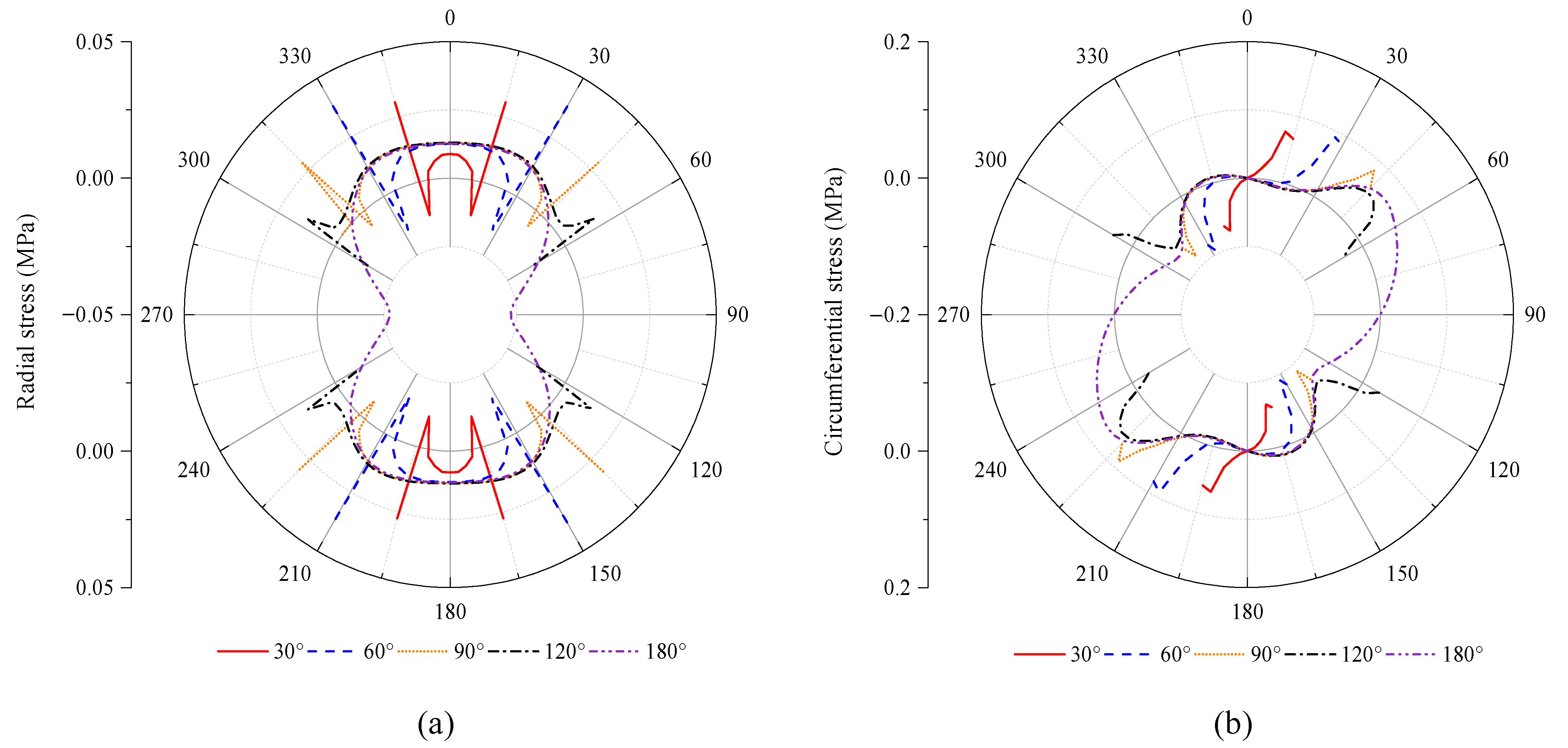
2.2. Effect of the Curvature on Interface Stresses
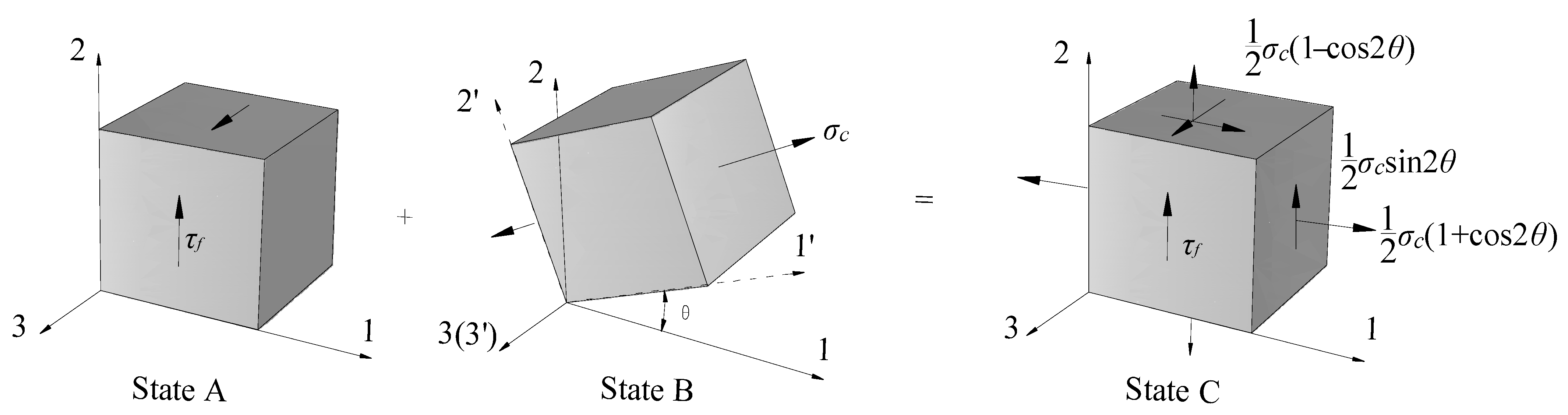
2.3. Effect of the Stress State on Peel Failure
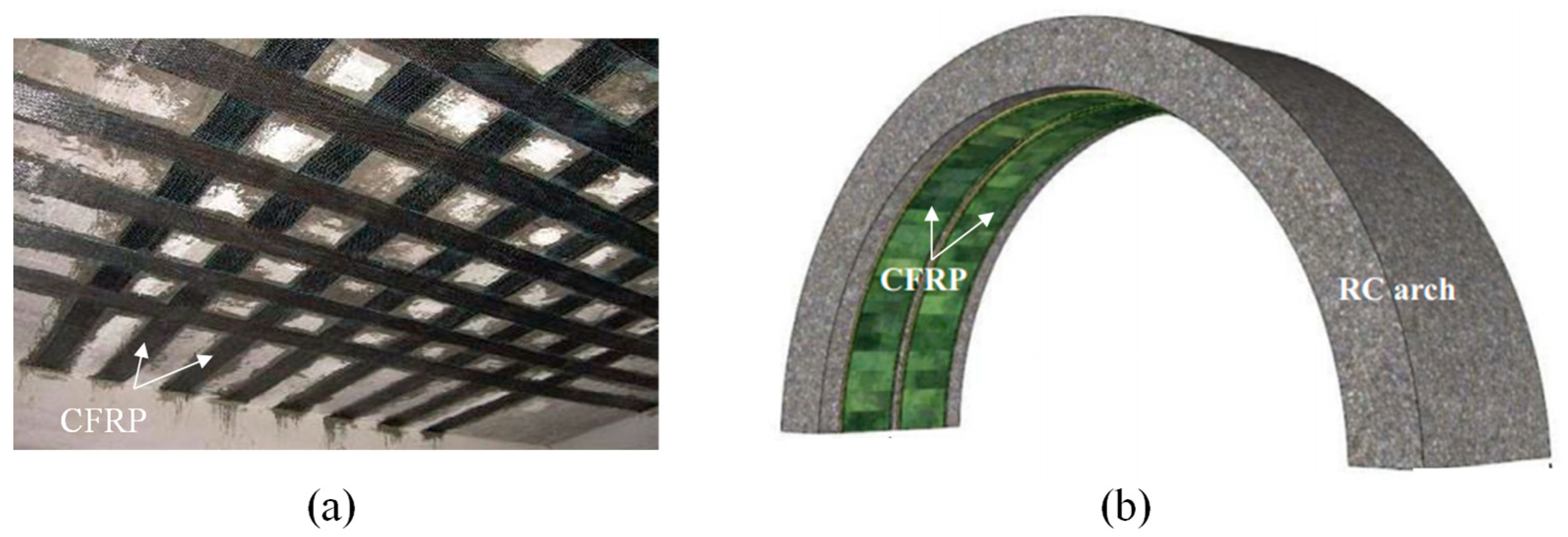
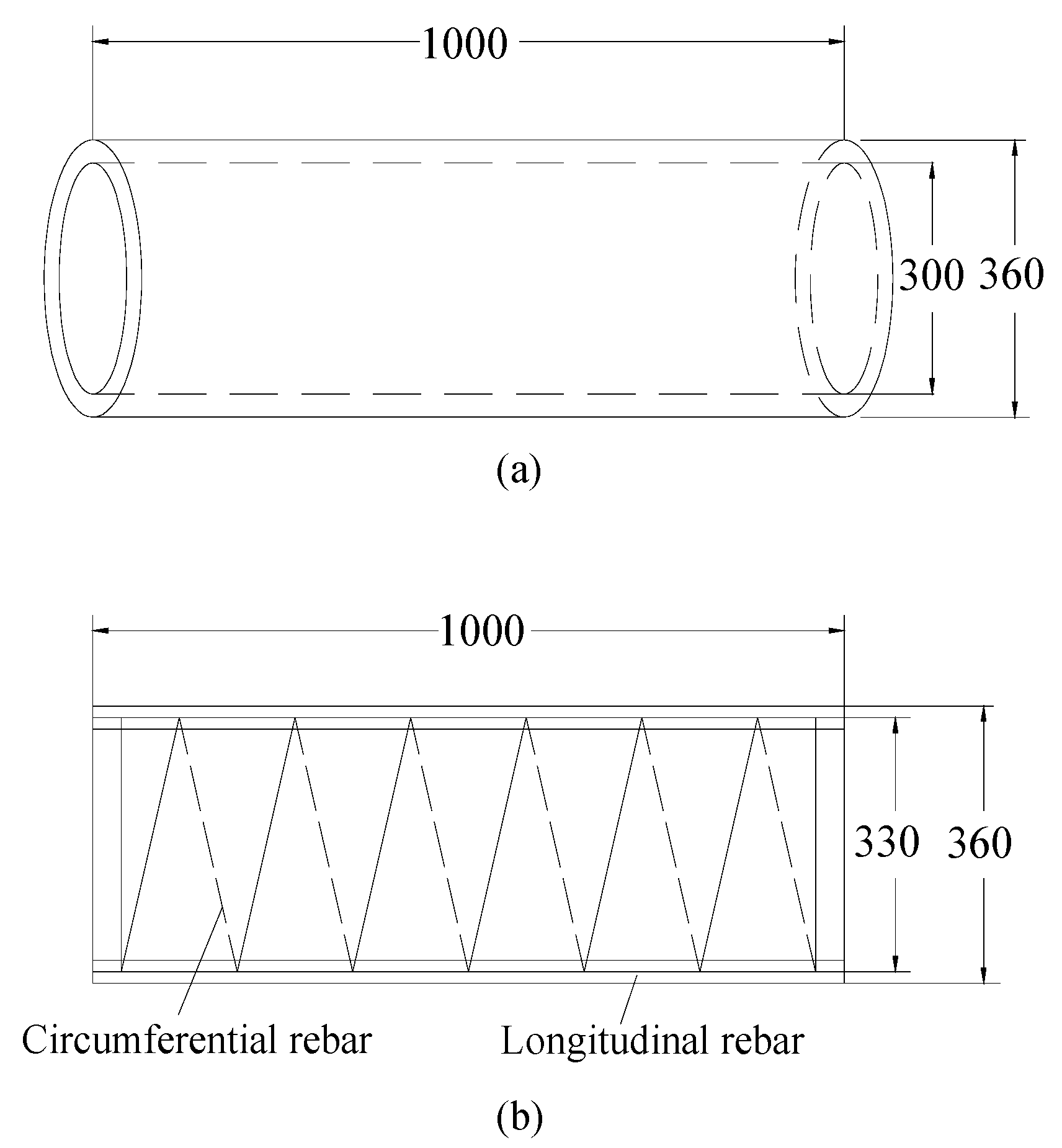
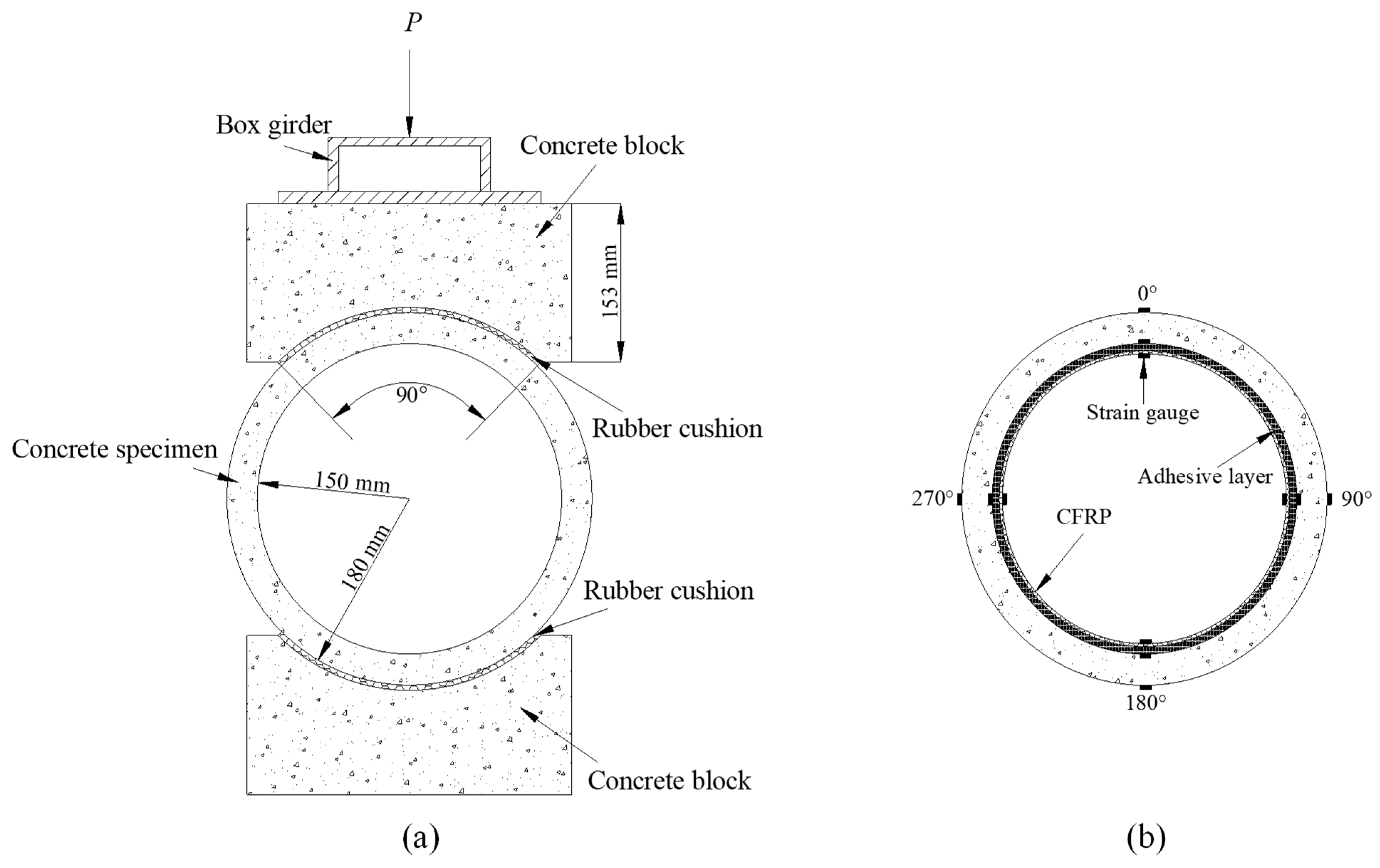
3. Experimental Study on a Tunnel Reinforced with CFRP
4. Numerical Simulation and Validation
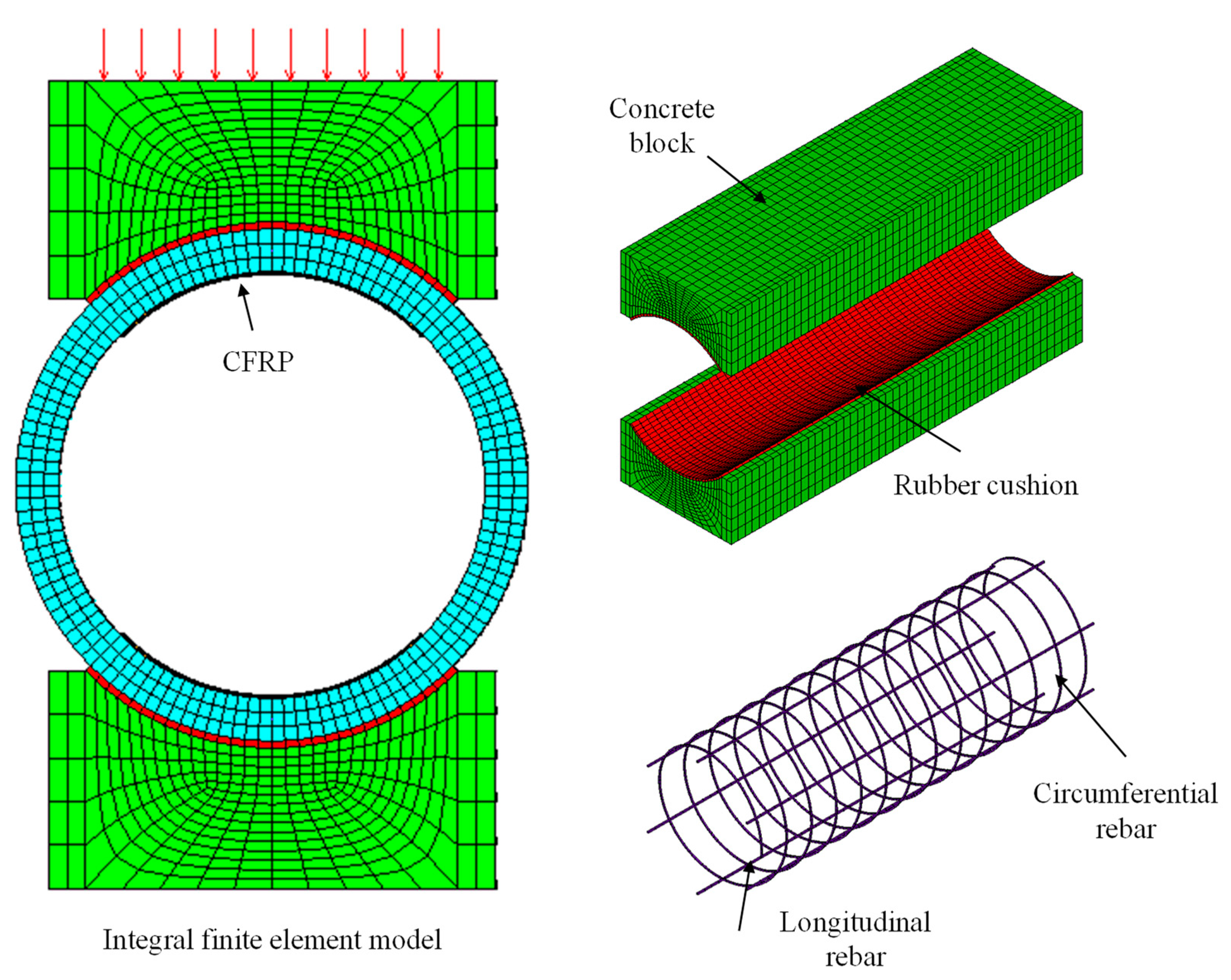
4.1. Numerical Model
4.2. Validation
5. Parametric Study
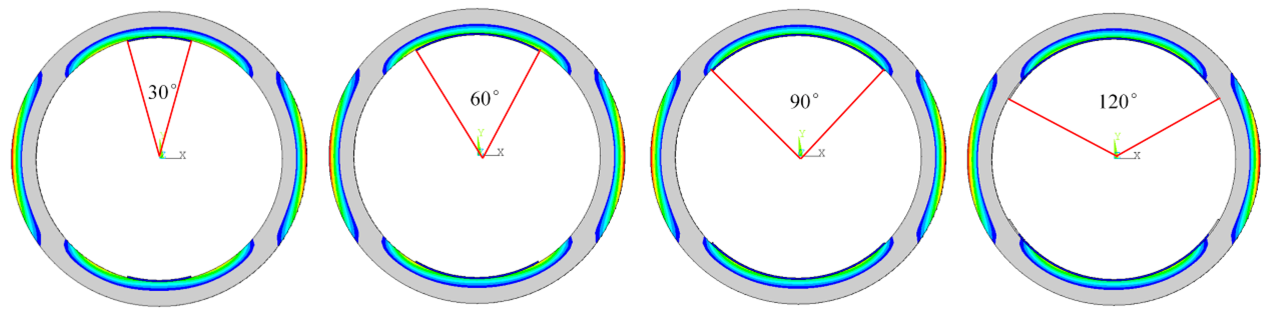
5.1. Effect of L
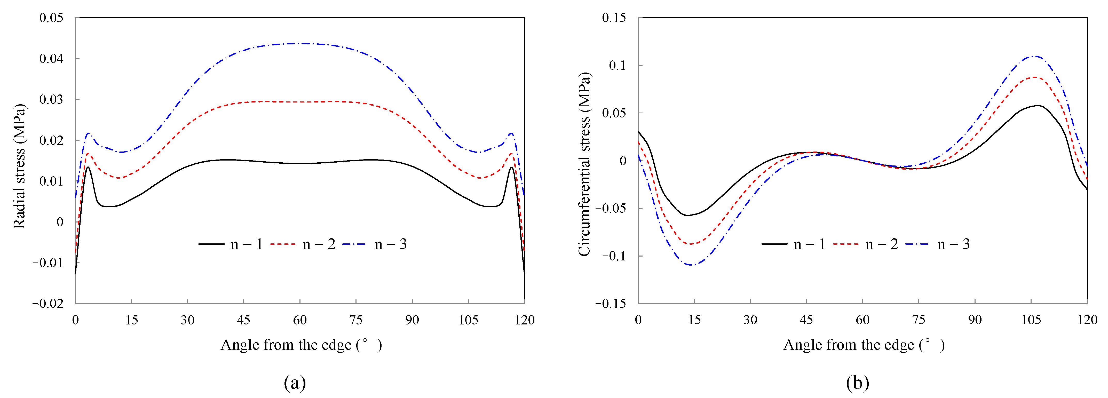
5.2. Effect of n
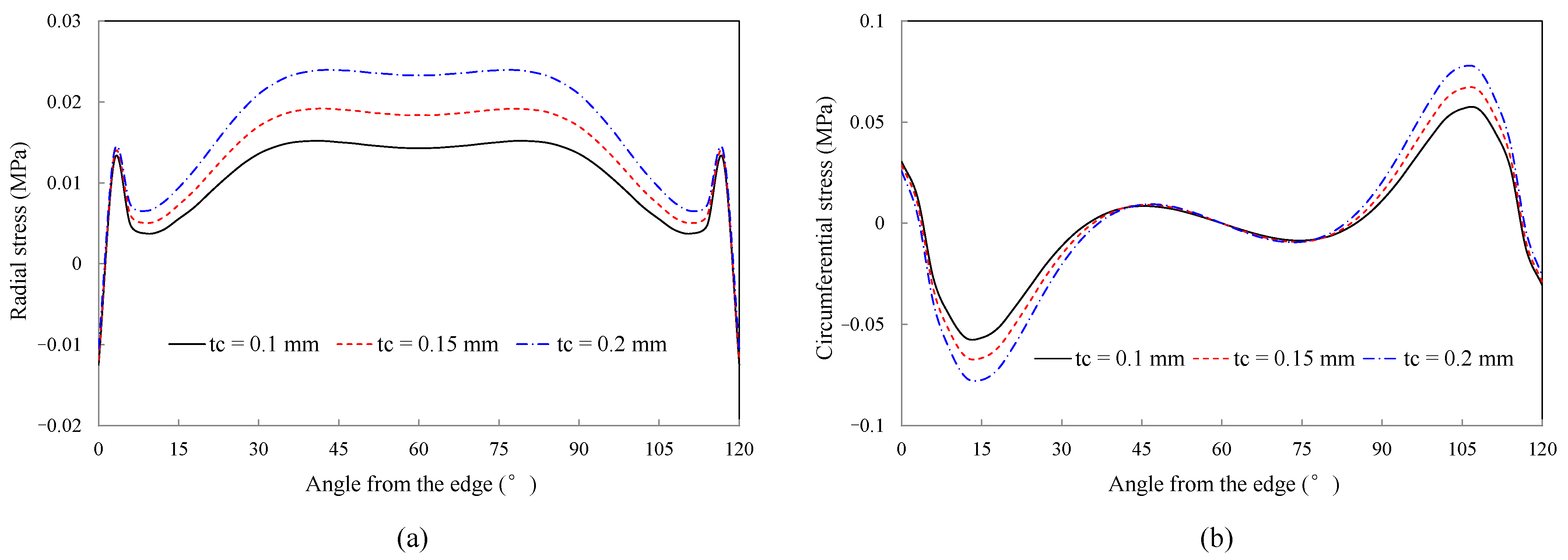
5.3. Effect of tc
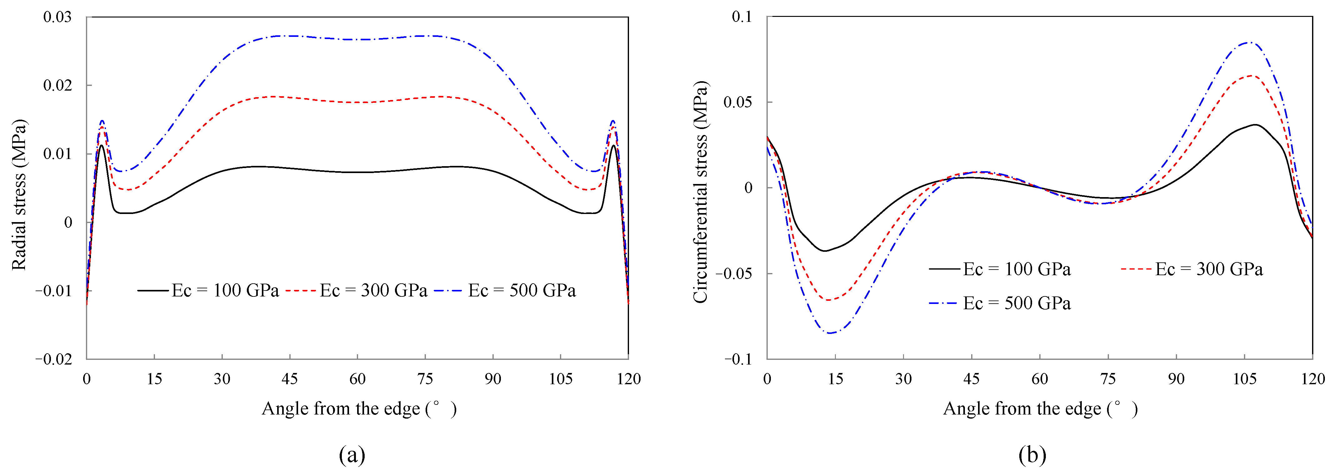
5.4. Effect of Ec
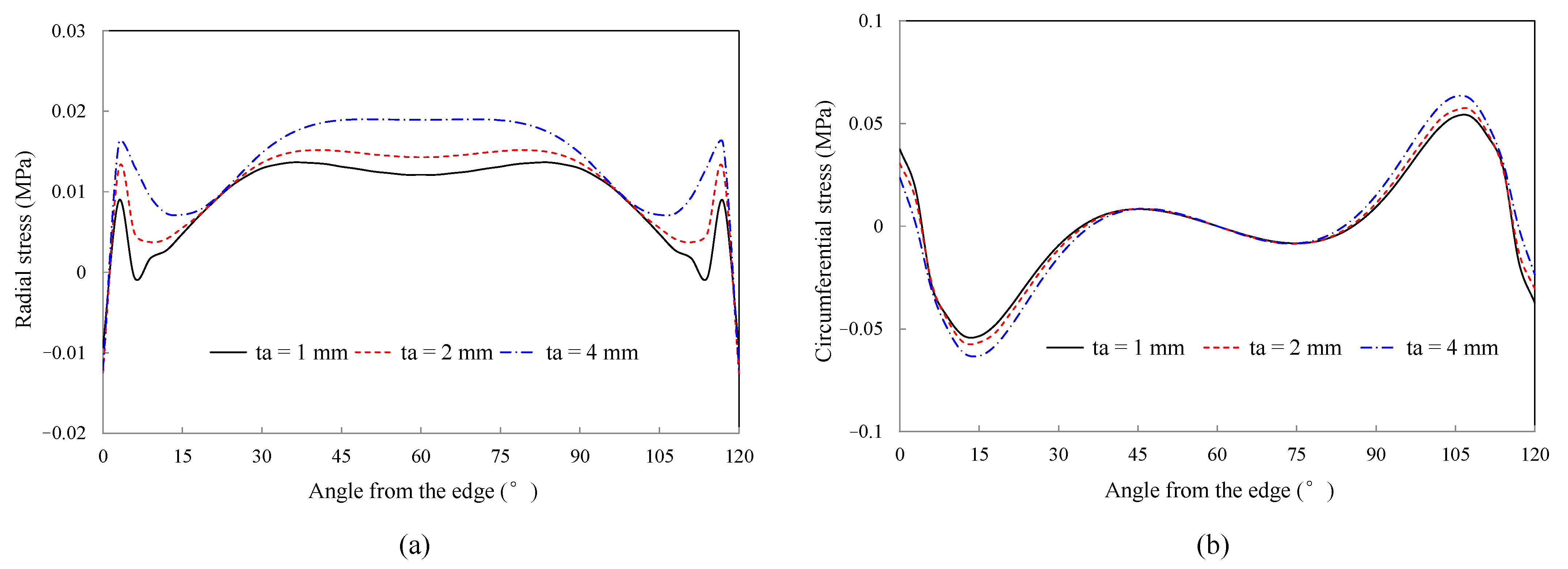
5.5. Effect of ta
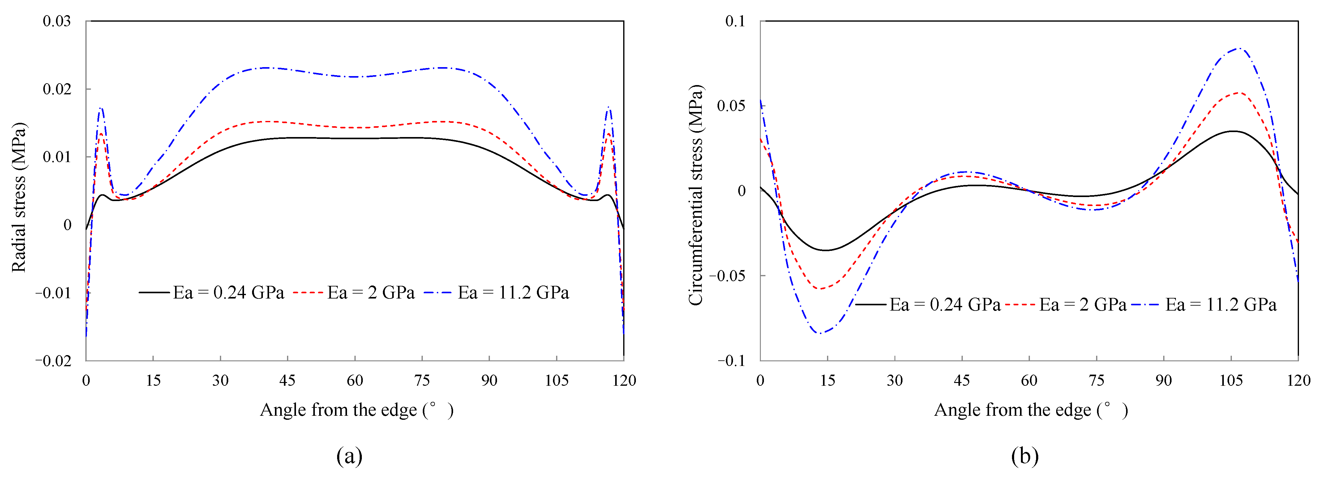
5.6. Effect of Ea
6. Conclusions
- (1)
- The analytical results reveal that the interface curvature has a significant effect on the interface radial stresses. With decreasing the radius of the curvature, the interface radial stresses increase significantly.
- (2)
- The numerical results reveal that the reinforced curved interface stresses are mainly affected by the CFRP’s length, layer, thickness, elastic modulus, and the adhesive’s thickness, elastic modulus. In engineering practice, these reinforcement parameters should be optimized to decrease the interface stresses and prevent premature peel failure of the structure.
- (3)
- For the adhesive, decreasing the elastic modulus and thickness of the adhesive layer can significantly improve the stress state of the reinforced interface. For the CFRP, on the premise of meeting the structural bearing requirements, the pasted length of CFRP should be large enough to at least cover all the concrete tensile areas, and the CFRP with smaller thickness, smaller elastic modulus and fewer layers is conducive to the full utilization of materials and long-term combined work of the concrete and CFRP.
Author Contributions
Funding
Institutional Review Board Statement
Informed Consent Statement
Data Availability Statement
Conflicts of Interest
References
- Liu, D.; Huang, H.; Yue, Q.; Xue, Y.; Wang, M. Behaviour of tunnel lining strengthened by textile-reinforced concrete. Struct. Infrastruct. Eng. 2015, 12, 964–976. [Google Scholar] [CrossRef]
- Wang, T.-T.; Lee, C.-H. Life-Cycle Design Considerations for Hydraulic Tunnels: Lessons Learned from Inspection and Maintenance Cases. J. Perform. Constr. Facil. 2013, 27, 796–806. [Google Scholar] [CrossRef]
- Meier, U.; Deuring, M. CFRP Bonded Sheets, FRP Reinforcement for Concrete Structures: Properties and Applications; Elsevier Science Publishers: Amsterdam, The Netherlands, 1993. [Google Scholar]
- Zeng, J.-J.; Liao, J.; Ye, Y.-Y.; Guo, Y.-C.; Zheng, Y.; Tan, L.-H. Behavior of FRP spiral strip-confined concrete under cyclic axial compression. Constr. Build. Mater. 2021, 295, 123544. [Google Scholar] [CrossRef]
- Liao, J.J.; Zeng, J.J.; Gong, Q.M.; Quach, W.M.; Gao, W.Y.; Zhang, L. Design-oriented stress-strain model for FRP-confined ultra-high performance concrete (UHPC). Constr. Build. Mater. 2022, 318, 126200. [Google Scholar] [CrossRef]
- Liao, J.J.; Zeng, J.J.; Chen, J.; Li, J.X.; Yuan, J.S. Stress-strain behavior and design-oriented model for FRP spiral strip-confined concrete. Compos. Struct. 2022, 293, 115747. [Google Scholar] [CrossRef]
- Wang, Q.; Zhu, H.; Su, W.; Du, H.; Chen, D. Fatigue performance of CFRP reinforced pretensioned prestressed beams. Constr. Build. Mater. 2022, 324, 126509. [Google Scholar] [CrossRef]
- Hollaway, L.C. A review of the present and future utilisation of FRP composites in the civil infrastructure with reference to their important in-service properties. Constr. Build. Mater. 2010, 24, 2419–2445. [Google Scholar] [CrossRef]
- Mugahed Amran, Y.H.; Alyousef, R.; Rashid, R.S.M.; Alabduljabbar, H.; Hung, C.-C. Properties and applications of FRP in strengthening RC structures: A review. Structures 2018, 16, 208–238. [Google Scholar] [CrossRef]
- Qin, G.; Yang, F.; Jin, D. Stress Transferring Mechanism of a Pressure Tunnel Lining Strengthened with CFRP. Lat. Am. J. Solids Struct. 2021, 18, 405–423. [Google Scholar] [CrossRef]
- Yao, J.; Teng, J.; Chen, J. Experimental study on FRP-to-concrete bonded joints. Compos. Part B Eng. 2004, 36, 99–113. [Google Scholar] [CrossRef]
- Dai, J.; Ueda, T.; Sato, Y. Development of the Nonlinear Bond Stress–Slip Model of Fiber Reinforced Plastics Sheet–Concrete Interfaces with a Simple Method. J. Compos. Constr. 2005, 9, 52–62. [Google Scholar] [CrossRef] [Green Version]
- Cao, S.Y.; Chen, J.F.; Pan, J.W.; Sun, N. ESPI Measurement of Bond-Slip Relationships of FRP-Concrete Interface. J. Compos. Constr. 2007, 11, 149–160. [Google Scholar] [CrossRef]
- Cui, E.; Jiang, S.; Wang, J.; Zeng, X. Bond behavior of CFRP-concrete bonding interface considering degradation of epoxy primer under wet-dry cycles. Constr. Build. Mater. 2021, 292, 123286. [Google Scholar] [CrossRef]
- Neubauer, U.; Rostasy, F.S. Bond failure of concrete fiber reinforced polymer plates at inclined cracks-experiments and fracture mechanics model. In Proceedings of the 4th International Symposium on Fiber Reinforced Polymer Reinforcement for Reinforced Concrete Structures ACI, Farmington Hills, MI, USA, 1 August 1999; pp. 369–382. [Google Scholar]
- Monti, M.; Renzelli, M.; Luciani, P. FRP adhesion in uncracked and cracked concrete zones. In Fiber-Reinforced Polymer Reinforcement for Concrete Structures: Proceeding of the 6th International Symposium on FRP Reinforcement for Concrete Structures, Singapore, 8–10 July 2003; World Scientific Publications: Singapore, 2003; pp. 183–192. [Google Scholar]
- Nakaba, K.; Toshiyuki, K.; Tomoki, F.; Yoshizawa, H. Bond behavior between fiber-reinforced polymer laminates and concrete. ACI Struct. J. 2001, 98, 359–367. [Google Scholar]
- Savioa, M.; Farracuti, B.; Mazzotti, C. Non-linear bond-slip law for FRP-concrete interface. In Fiber-Reinforced Polymer Reinforcement for Concrete Structures: Proceeding of the 6th International Symposium on FRP Reinforcement for Concrete Structures, Singapore, 8–10 July 2003; World Scientific Publications: Singapore, 2003; pp. 163–172. [Google Scholar]
- Roberts, T.M. Approximate analysis of shear and normal stress concentrates in the adhesive layer of Plated RC Beams. Struct. Eng. 1989, 67, 222–233. [Google Scholar]
- Roberts, T.M.; Haji-Kazemi, H. Theoretical study of the behavior of reinforced concrete beams strengthened by externally bonded steel plates. Proc. Inst. Civ. Eng. 1989, 87, 39–55. [Google Scholar]
- Vilnay, O. The analysis of reinforced concrete beams strengthened by epoxy bonded steel plates. Int. J. Cem. Compos. Light. Concr. 1988, 10, 73–78. [Google Scholar] [CrossRef]
- Liu, Z.H.; Zhu, B.L. Analytical solutions for R/C beams strengthened by externally bonded steel plates. J. Tongji Univ. 1994, 22, 21–26. [Google Scholar]
- Täljsten, B. Strengthening of beams by plate bonding. J. Mater. Civ. Eng. 1997, 9, 206–212. [Google Scholar] [CrossRef]
- Malek, A.M.; Saadatmanesh, H.; Ehsani, M.R. Prediction of failure load of R/C beams strengthened with FRP plate due to stress concentration at the plate end. ACI Struct. J. 1998, 95, 142–152. [Google Scholar]
- Rabinovich, O.; Frostig, Y. Closed-Form High-Order Analysis of RC Beams Strengthened with FRP Strips. J. Compos. Constr. 2000, 4, 65–74. [Google Scholar] [CrossRef]
- Shen, H.S.; Teng, J.G.; Yang, J. Interfacial stresses in beams and slabs bonded with thin plate. J. Eng. Mech. 2001, 127, 399–406. [Google Scholar]
- Monti, G.; Liotta, M. Tests and design equations for FRP-strengthening in shear. Constr. Build. Mater. 2007, 21, 799–809. [Google Scholar] [CrossRef]
- Wang, J.; Zhang, C. A three-parameter elastic foundation model for interface stresses in curved beams externally strengthened by a thin FRP plate. Int. J. Solids Struct. 2010, 47, 998–1006. [Google Scholar] [CrossRef] [Green Version]
- Lu, X.Z. Study on FRP-Concrete Interface. Ph.D. Thesis, Tsinghua University, Beijing, China, 2004. [Google Scholar]
- Lorenzis, L.D.; Zavarise, G. Interfacial stress analysis and prediction of debonding for a thin plate bonded to a curved substrate. Int. J. Non-Linear Mech. 2009, 44, 358–370. [Google Scholar] [CrossRef] [Green Version]
- Wang, L.Y. The Experimental Study on Pressure Conduit of Ferroconcrete Reinforced by Fabric Reinforced Plastic. Master’s Thesis, Wuhan University, Wuhan, China, 2004. [Google Scholar]
- Hugo, C.B.; Carlos, C.; Manuel, A.G.S. linear and nonlinear analysis of bond slip models for interfaces between FRP composites and concrete. Compos. Part B 2013, 45, 1554–1568. [Google Scholar]
- Obaidat, Y.T.; Heyden, S.; Dahlblom, O. Evaluation of Parameters of Bond Action between FRP and Concrete. J. Compos. Constr. 2013, 17, 626–635. [Google Scholar] [CrossRef]
- Furtado, A.; Rodrigues, H.; Arêde, A.; Varum, H. Experimental tests on strengthening strategies for masonry infill walls: A literature review. Constr. Build. Mater. 2020, 263, 120520. [Google Scholar] [CrossRef]
- Liu, Y.; Dong, A.; Zhao, S.; Zeng, Y.; Wang, Z. The effect of CFRP-shear strengthening on existing circular RC columns under impact loads. Constr. Build. Mater. 2021, 302, 124185. [Google Scholar] [CrossRef]


| Parameter | Ea | ta | Ec | tc | L | F |
|---|---|---|---|---|---|---|
| Value | 2 GPa | 1 mm | 250 GPa | 0.111 mm | 150 mm | 50 N/m |
| Material | Elastic Modulus (GPa) | Poisson’s Ratio | Density (kg/m3) |
|---|---|---|---|
| C30 concrete | 30 | 0.167 | 2400 |
| Longitudinal rebar | 210 | 0.3 | 7850 |
| Circumferential rebar | 210 | 0.3 | 7850 |
| Rubber cushion | 7.8 | 0.48 | 1200 |
| CFRP | 235 | 0.28 | — |
| Adhesive layer | 2.5 | 0.35 | — |
| Performance Items | Performance Requirements | ||
|---|---|---|---|
| Grade A Adhesive | Grade B Adhesive | ||
| Adhesive layer performance | Tensile strength (MPa) | ≥40 | ≥30 |
| Modulus of elasticity under tension (MPa) | ≥2500 | ≥1500 | |
| Elongation rate (%) | ≥1.5 | ||
| Flexural strength (MPa) | ≥50 | ≥40 | |
| Compressive strength (MPa) | ≥70 | ||
| Bonding capacity | Positive tensile bond strength with concrete (MPa) | ≥2.5 | |
| Force (kN) | Concrete Strain | CFRP Strain | ||||
|---|---|---|---|---|---|---|
| Experimental Results (10−6) | Numerical Results (10−6) | Differences | Experimental Results (10−6) | Numerical Results (10−6) | Differences | |
| 5 | −22.20 | −23.02 | 3.7% | −23.39 | −23.37 | −0.1% |
| 10 | −45.14 | −42.96 | −4.8% | −53.12 | −46.76 | −12.0% |
| 15 | −68.08 | −62.02 | −8.9% | −82.86 | −70.15 | −15.3% |
| 20 | −91.03 | −82.84 | −9.0% | −112.59 | −93.54 | −16.9% |
| Parameter | Reference Value | Discussion Value |
|---|---|---|
| L | 180° | 30°, 60°, 90°, 120° |
| Ea | 2 GPa | 0.24, 2, 11.2 |
| ta | 2 mm | 1, 2, 4 |
| Ec | 235 GPa | 100, 300, 500 |
| tc | 0.1 mm | 0.1, 0.15, 0.2 |
| n | 1 | 1, 2, 3, 4 |
Publisher’s Note: MDPI stays neutral with regard to jurisdictional claims in published maps and institutional affiliations. |
© 2022 by the authors. Licensee MDPI, Basel, Switzerland. This article is an open access article distributed under the terms and conditions of the Creative Commons Attribution (CC BY) license (https://creativecommons.org/licenses/by/4.0/).
Share and Cite
Yang, F.; Qin, G.; Liu, K.; Xiong, F.; Liu, W. Analytical and Numerical Study on the Performance of the Curved Surface of a Circular Tunnel Reinforced with CFRP. Buildings 2022, 12, 2042. https://doi.org/10.3390/buildings12112042
Yang F, Qin G, Liu K, Xiong F, Liu W. Analytical and Numerical Study on the Performance of the Curved Surface of a Circular Tunnel Reinforced with CFRP. Buildings. 2022; 12(11):2042. https://doi.org/10.3390/buildings12112042
Chicago/Turabian StyleYang, Fan, Gan Qin, Kang Liu, Feng Xiong, and Wu Liu. 2022. "Analytical and Numerical Study on the Performance of the Curved Surface of a Circular Tunnel Reinforced with CFRP" Buildings 12, no. 11: 2042. https://doi.org/10.3390/buildings12112042