Article

Wind Buckling Analysis of a Large-Scale Open-Topped Steel Tank with Harmonic Settlement-Induced Imperfection

1
Institute of Safety Technology, CNPC Research Institute of Safety & Environment Technology, Beijing 102206, China
2
QHSE Department, Petrochina Changqing Oilfield Company, Xi’an 710021, China
3
Petrochina Dalian Petrochemical Company, Dalian 116000, China
4
State Key Laboratory of Coastal and Offshore Engineering, Dalian University of Technology, Dalian 116024, China
5
Inititute of Earthquake Engineering, Faculty of Infrastructure Engineering, Dalian University of Technology, Dalian 116024, China
*
Author to whom correspondence should be addressed.
Buildings 2022, 12(11), 1973; https://doi.org/10.3390/buildings12111973
Submission received: 26 August 2022 / Revised: 2 November 2022 / Accepted: 10 November 2022 / Published: 14 November 2022
(This article belongs to the Special Issue Engineering Safety Monitoring and Management)

Abstract

:
In this study, the wind buckling capacity of an open-topped steel tank with harmonic settlement-induced imperfection is numerically investigated. Although the single effect of the wind load or differential settlement on the open-topped steel tanks is widely studied, the interaction of the two loads to the tank shell is scarcely examined. The prototype of a 100,000 m3 open-topped steel tank with a floating roof is selected, and the harmonic settlements (wave numbers n = 2, 3, and 4) and the wind profile considering internal pressure (EN 1993-4-1) are applied. Firstly, the finite element model is established and validated by the replication of peer-reviewed research. Then, the wind buckling analysis of the tank shell with harmonic settlement-induced imperfection is studied. Next, the effects of the harmonic settlement-induced imperfection (HSII) and the wind attack angle (WAA) on the wind buckling capacity are discussed. The results show that the effect of the HSII on the wind buckling capacity is complex. When the wind attack angle is the case of β = 0 ° , the wind load capacities ( λ cig ) with HSIIs decrease to 73.4% (wave number n = 2 ), 37.5% (wave number n = 3 ) and 41.3% (wave number n = 4 ) of the non-settlement wind load capacity ( λ cg ). Given that the case of β = 0 ° is the basis, when the harmonic settlement level is low, such as settlement load No.1 and No.2, the biggest increase of wind buckling capacity is less than 20% with an exception; when the harmonic settlement level is high, such as settlement load No.3, No.4 and No.5, the biggest increase of wind buckling capacity is more than 40%, with a few exceptions.

1. Introduction

The mechanical responses of various structures and components under environmental loads were investigated [1,2,3,4,5,6,7,8]. The wind load and differential settlement are usually taken into consideration for thin-walled structures, which may cause catastrophic failures, such as the buckling of the oil steel tank [9,10,11,12]. Vertical open-topped steel tanks, which are usually threatened by wind load and differential settlement, are widely used for oil storage in industrial plants. They usually consist of a thin bottom plate, a cylindrical shell with uniform or stepped thickness, and an open-top with a floating roof [13]. Considering the development of the oil industry and the cost of the construction, more and more large-scale open-topped oil storage tanks have been put into service in recent decades. With the usage of large-scale open-topped oil storage tanks, the destruction of storage tanks is directly related to serious economic losses and environmental problems.
Wind-induced buckling of steel oil tanks is of great concern in areas where hurricanes or typhoons may occur [14]. With finite element analysis (FEA) on the wind buckling of cylindrical shells considering several various imperfection modes, Greiner and Derler [15] reported that the stocky cylindric shells were sensitive to global eigenmode-shaped imperfections, while the longer cylinders were sensitive to local rectangular or ring shaped imperfections. Portela and Godoy [16,17] investigated the buckling of open-topped and roof-topped tanks due to wind load, in which the imperfection sensitivity was studied through the geometrically nonlinear analyses (GNA). Based on reduced energy mode, a reduced stiffness approach was used by Jaca et al. [18] to evaluate the lower bound of buckling of open-topped cylindrical tanks under wind load. The results showed that the buckling capacity obtained from the reduced stiffness approach constituted a lower bound than that obtained numerically and experimentally. In addition, Jaca and Godoy [19] performed FEA to study the moderate wind-induced damage of tanks during their construction. Considering the uniform thickness of the tank shell, Chen and Rotter [20] conducted FEA on the buckling of anchor cylindrical shells under wind pressure covering various tanks with different aspect ratios. Zhao and Lin [13] performed FEA on the buckling of six common practical open-topped tanks with volumes of m3 to m3 and aspect ratios (height-to-diameter) H/D < 1. It is worth noting that the internal pressure due to wind was included in their study [13]. Chiang and Guzey [21] numerically investigated the buckling behaviors of the open-top steel tanks under wind load with the additional internal pressure. The results indicated that the additional internal pressure generated by the wind on an open-top tank should not be neglected. It can be concluded that the open-topped steel tank draws a lot of attention, and the FEA is a commonly used method to study the buckling behavior under wind load.
The steel tanks are usually built on a relatively soft soil foundation, which makes them susceptible to failure due to differential settlement [22]. For the open-topped steel tanks, two key aspects should be considered, which are the strength limit state and the serviceability limit state [22]. To ensure the safety and serviceability of the tank shell, many researchers have investigated the effect of the settlement on the open-topped tank. Based on the inextensional linear thin shell theory, Malik et al. [23] derived a formulation to calculate a maximum allowable settlement by limiting the maximum allowable radial displacement. Kamyab and Palmer [24] found the limitation of the inextensional-theory-based method to the higher harmonic wave numbers and recommended a membrane and long wave solution to solve the problem. To determine the strength limit state, Marr et al. [25] proposed a different procedure for the allowable foundation settlement of a tank by combining the DeBeer relationship and beam theory. Jonaidi and Ansourian [26] conducted FEA for tanks with stepped thickness and found that the step thickness should be considered for wave numbers between 5 and 10 for open-top tanks. Godoy and Sosa [27] studied the behavior of tanks under localized settlement using FEA through linear analysis and GNA. The results showed that the equilibrium path based on the GNA is different from that based on the linear analysis. Gong and coworkers [28] also numerically studied the buckling behavior of the open-topped tanks subjected to harmonic settlement. The results showed that the critical harmonic settlement decreases more and more slightly with the increasing wave number. Based on the FEA, Bohra and Guzey [22] formulate a new method to evaluate the fitness of the tank under global settlement profiles, taking the effect of higher harmonics into account for open-topped steel tanks. In addition, innovative experiments and theories of the cylindrical shell are developing, such as the buckling analysis of the composite cylindrical shells [28,29], local buckling of axially compressed cylindrical shells [30], and the new methodology for the design of anisogrid composite lattice cylindrical shells [31]. In this study, we focus on the traditional oil steel tank.
Although steel tanks under a single load of settlement or wind pressure have been widely studied in recent years [13,21,22,27,32,33,34,35,36,37,38,39,40,41,42], the study of the interaction of the two key loads to the tank shell is rare. The harmonic settlement-induced imperfection has a clear engineering background. Because most of the existing oil storage tanks in China are built on collapsible soil along the river and coastal areas, the foundation of the tanks would produce differential settlements. More importantly, these areas are susceptible to wind loads. Hence, there is a high possibility of risk that steel tanks suffer differential settlement first and then undergo wind load. Moreover, the deformation of the tank shell is highly related to the material and geometric nonlinear. Therefore, the superposition principle for linear elastic analysis cannot be applied directly for the coupling of differential settlement and wind load. In this study, the wind-induced buckling capacity of the steel tank is investigated numerically with harmonic settlement-induced imperfection. We aim to understand the interaction of the wind load and differential settlement for the large-scale open-topped steel tank.

2. Computational Model

2.1. Steel Tank Prototype

The large-scale oil steel tanks, with a volume of no less than 100,000 m3, are widely used in the petroleum industry [43]. In this study, a 100,000 m3 open-topped steel tank with a floating roof (see Figure 1) is selected as an example to investigate the buckling capacity subjected to wind pressure considering harmonic settlement-induced imperfection (HSII). The tank consists of ten courses with a diameter of 80 m and a height of 21.88 m (see Figure 1). Hence, the aspect ratio can be determined to be 0.274. The geometric and material parameters for each course are listed in Table 1. It is noted that the tenth course is constructed with angle iron, which strengthens the stiffness of the tank.

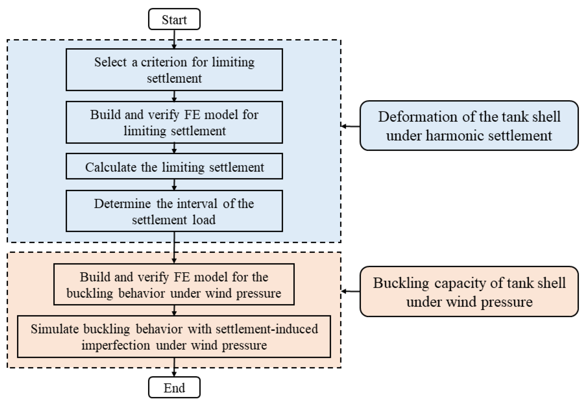
2.2. Analysis Procedure and Finite Element Model

The analysis procedure is divided into two main steps: (1) settlement-induced deformation analysis of the tank shell under harmonic settlement; and (2) buckling analysis of the tank shell under wind pressure with the HSII. Contrary to the traditional analysis procedure of the wind load capacity, the harmonic settlement is preloaded before the wind pressure in this study. The flowchart of the analysis procedure is shown in Figure 2. In the first step, the main goal is to determine the interval of the harmonic settlement to produce distinct-leveled imperfection. In the following step, the buckling analysis of the tank shell with the HSII under wind pressure is investigated. More importantly, the effect of the wind attack angle (WAA) is also considered in the second step.
In the analysis procedure, the settlement is always decomposed into the harmonic settlement. The limiting harmonic settlement for a given harmonic wave number is defined to be the settlement value at which the tank failure takes place and the tank is not fit for use in the current state. The failure criterion is of significance for the limiting settlement of steel tanks. The existing criteria were proposed to determine the limiting settlement, such as the total strain level criterion [25] and the plastic strain level criterion [44]. However, these criteria may not be sufficiently safe, since it allows the material to go beyond yielding. To ensure the sufficient safety of the steel tank under the harmonic settlement, a new failure criterion in which the maximum membrane stress level is limited to the yield stress of the material was proposed by Bohra and Guzey [22]. The new maximum membrane yield stress criterion is preferable because oil tanks may undergo possible further environmental loadings, such as wind or earthquake. Hence, the new maximum membrane yield stress criterion [22] is selected to determine the limiting harmonic settlement in this study. Based on the new failure criterion, the Riks method is applied to capture the limiting harmonic settlement, and the geometric and material nonlinear is considered.
With regard to the wind load, the pressure distribution specified by the EN 1993-4-1 [45] is used to investigate the buckling behavior of the tank shell, and the wind profile is shown in Figure 3. This is because the internal inward pressure should be considered [41] while the steel tank is with an open-topped geometry. More importantly, the wind profile is appropriate to the aspect ratio of the steel tank used in this study [13]. Under the wind pressure, a linear bifurcation analysis (LBA) and a geometrically and materially nonlinear analysis (GMNA) are conducted. The LBA provides the upper bound of stability carrying capacity, [45] while the GMNA reflects the realistic buckling behavior of a tank shell. Moreover, Chiangand and Guzey [21] reported that the maximum load increment of the post-buckling analysis is related to the LBA-based buckling capacity. Hence, the LBA is conducted first to obtain a static elastic estimation of the buckling capacity.
The finite element analysis (FEA) of the 100,000 m3 steel tank is conducted in the Abaqus 6.14. The material parameters are listed in Table 2. The true stress-strain relationship can be evaluated using the method reported in reference [46]. Figure 4 shows the true stress-strain curve for SPV490Q, Q345R, and Q235B.
The gravity is applied with the pinned boundary condition at the bottom of the tank shell before the application of the harmonic settlement. However, the hydrostatic liquid pressure is not considered because the pressure helps stabilize the tank [13,22]. For the harmonic settlement-induced deformation analysis, the bottom of the tank in the vertical direction is excited by the harmonic wave u = u n cos ( n θ ) , where u is settlement along the bottom of the tank, u n is amplitude of the n th harmonic settlement, θ is the circumferential central angle, and n is harmonic wave number. Specifically, the AnalyticalField load distribution in the Abaqus can be used to apply the harmonic settlement. Furthermore, the translations in both the radial and the circumferential directions are constrained at the bottom of the shell, and the rotation freedom is free [22,32]. The limiting settlements of the steel tank are determined for harmonic wave numbers n = 2, 3, and 4 [22,32,34]. For the wind buckling analysis, the pinned boundary condition (Ux, Uy, Uz = 0, Rotx, Roty, Rotz are free) is applied to the bottom of the FE model.
In this study, the four nodes, doubly curved, quadrilateral shell element with reduced integration and hourglass control, S4R, is used to discrete the steel tank. The mesh size is about 200 mm, which is decided by a mesh convergence study. In the mesh convergence study, the harmonic settlement is applied first and then the wind load is pressured. The amplitudes of harmonic settlement are 500 mm, 300 mm, and 100 mm, corresponding to the harmonic wave numbers n = 2, 3, and 4, respectively. The windward meridian is arranged to go through the starting point ( θ = 0 ° ) of the harmonic settlement. Figure 5 presents the mesh size versus the normalized buckling capacity and the number of elements. It can be observed that the mesh size of 200 mm is appropriate in terms of computational efficiency and accuracy. A refined mesh with 4 elements is used for the angle iron to capture the stress distribution more accurately. The finite element mesh of the steel tank is shown in Figure 6.

3. Validation of FE Model

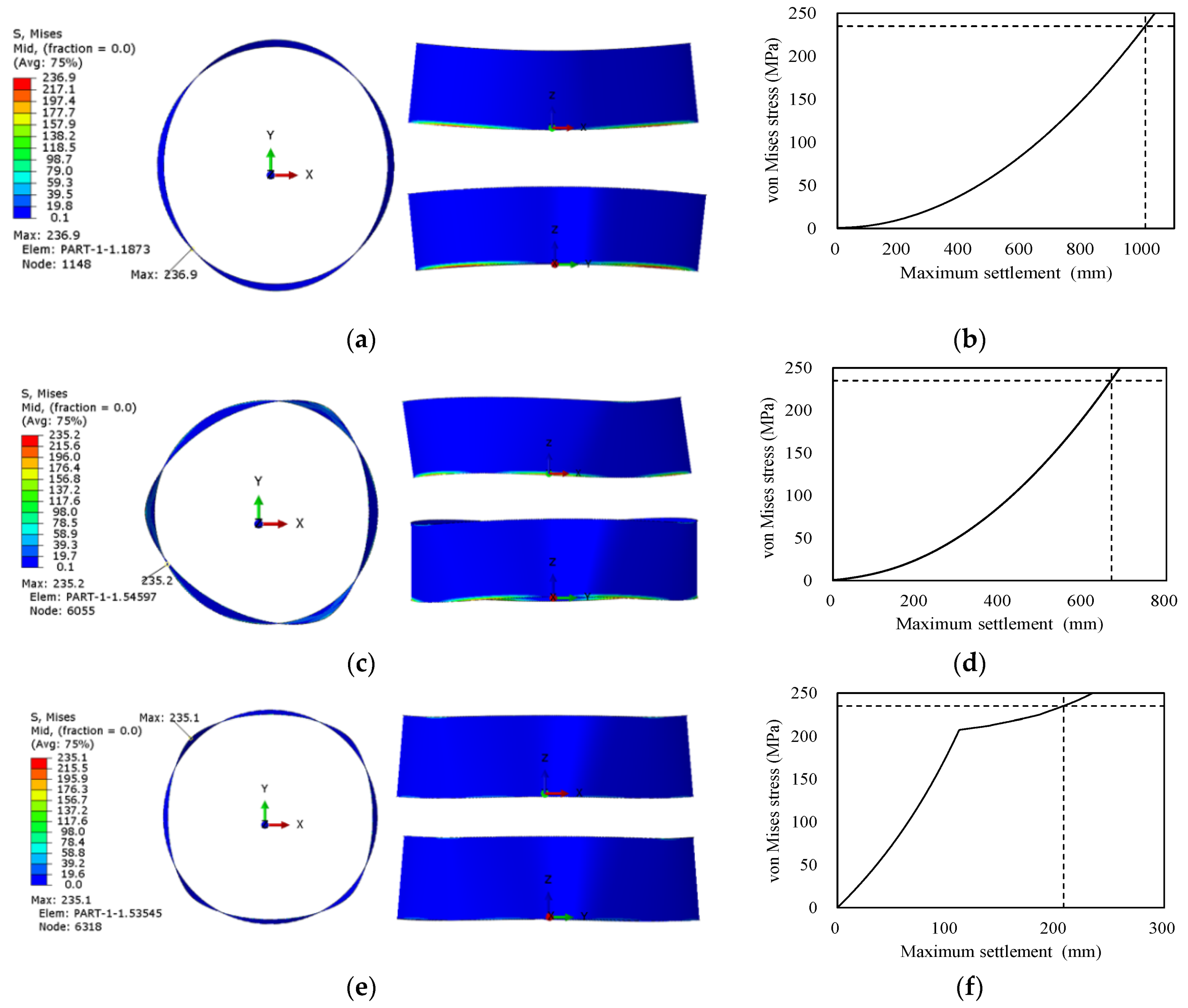
3.1. Deformation of the Tank Shell under Pure Harmonic Settlement

The FE method introduced in Section 2 is the same as that used in reference [22]. To validate the FE model used in this study, the simulation of the TK-300 steel tank [22] under the harmonic settlement is replicated. The mesh size for the TK-300 steel tank [22] is controlled by the following equation [22]:
a = 0.5 R t
where a is the length of the shell element; R is the radius of the tank; and t is the thickness of the thinnest shell course. This mesh size equation was decided after performing a mesh convergence study [22]. In this section, the mesh size is about 200 mm for the discretization of the TK-300 steel tank.
Figure 7 shows the comparison between the results of tank model TK-300 studied by Bohra and Guzey [22] and by the authors. The curve plotted by Bohra and Guzey [22] is higher than that by the authors in the heavy nonlinear region. The small gap is due to the differences in material parameters. However, the limiting settlements are consistent with each other. Hence, it can be concluded that the FE method used to determine the limiting harmonic settlement in this study is appropriate.

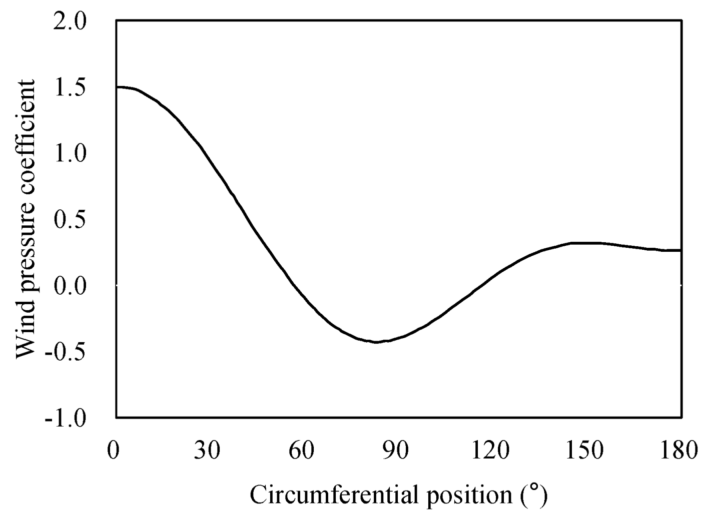
3.2. Buckling Capacity of Tank Shell under Pure Wind Pressure

For the sake of convenience, the reference pressure is specified as 1 kPa, which denotes a wind velocity of 40.8 m/s at a height of 10 m [13]. The LBA-based wind buckling capacity factor is denoted as λ cl . The first and second wind buckling capacity factors λ cl , 1 and λ cl , 2 are listed in Table 3. Lin and Zhao [13] conducted the LBA of the same 100,000 m3 steel tank, and the result is also presented in Table 3. More importantly, Figure 8 and Figure 9a,b show the deformations of the LBA. It is observed that the LAB results determined in this study are consistent with the results yielded by Lin and Zhao [13]. Therefore, the method for LBA in this study is appropriate.
To investigate the realistic buckling behavior for the 100,000 m3 steel tank, the geometrically nonlinear analysis (GNA) using the Riks algorithm is conducted. The maximum load increment of the post-buckling analysis is determined to be less than 3% of λ cl , 1 according to the maximum load increment criterion [41]. Table 3 lists the GNA-based wind buckling capacity factor λ cg . A geometrically nonlinear analysis (GNA) for the same steel tank was also conducted by Lin and Zhao [13]. The comparison of GNA buckling deformations at maximum load for the tank is presented in Figure 9c, and the geometrically nonlinear equilibrium path for the tank is plotted in Figure 10. It is observed that the critical buckling wind load, the equilibrium path and the deformation are extremely close to the Zhao’s results. Hence, the GNA method used in this study is also appropriate.

4. Wind Buckling Analysis of the Steel Tank with Harmonic Settlement-Induced Imperfection

4.1. Deformation of the Tank Shell under Harmonic Settlement

According to the new maximum membrane yield stress criterion, the limiting stress should be determined. The materials used in this study are SPV490, Q345R, and Q235B. The material Q235B has the lowest nominal yield stress value at 235 MPa. Hence, the limiting settlement value corresponds to the settlement at which the maximum membrane stress in the steel tank reaches the yield stress of 235 MPa. Figure 11 plots the deformed tank shells and settlement-von Mises membrane stress relationships for three harmonic wave numbers. It is observed that the deformed tank shells are symmetric, and there are four, six, and eight identical deformed tank segments at every 90 ° , 60 ° , and 45 ° when the harmonic wave numbers are 2, 3, and 4, respectively. In addition, it is found from Figure 11 that the relationships of settlement-von Mises membrane stress for the three harmonic settlement loads are nonlinear, especially when n = 4. The singularity point in Figure 11f is the elastic-plastic cut-off point of the Q235 steel in the simulation in this study. The limiting settlements for harmonic wave numbers n = 2, 3, and 4 are listed in Table 4, where the value of the limiting settlement decreases as the harmonic wave number increases.

4.2. Buckling Behavior of Steel Tank under Wind Pressure

As mentioned above, we focus on the wind buckling capacity of a large-scale open-topped tank shell with HSII. The load procedure is prescribed in the following three steps: (1) apply the gravity to the tank shell; (2) excite the harmonic settlements listed in Table 4 to produce geometric imperfections; and (3) apply the wind pressure to the deformed tank shell until buckling occurs. The wind-induced buckling is usually within the elastic limits. However, the deformation of a tank under settlement may go beyond yield, which depends on the magnitude of the settlement to some extent (see Figure 11f). The wind buckling analysis of a steel tank with harmonic settlement-induced imperfection is the second-order analysis after the deformation within the settlement. Hence, the wind buckling analysis may go beyond yield. As shown in Figure 12, the windward meridian is arranged to go through the starting point ( θ = 0 ° ) of the harmonic settlement and the wind attack angle is the case of β = 0 ° . The nonlinear equilibrium paths for three types of HSII are plotted in Figure 13. Table 5 lists the buckling load factor λ cig , where superscript cig denotes the critical buckling wind load with the geometric imperfection using the GMNA. It can be found that the ratio of λ cig to λ cg is less than 100%, which means that the HSIIs weaken the wind load capacity of the tank shell.
The deformed tank shells are shown in Figure 14. The normalized radial displacement is defined to be the ratio of radial displacement to the radius of the tank. It can be observed that the configurations of the tank shell are not significantly affected by the wind load when compared to the numbers in Figure 11. To explore the effect of the wind load on the harmonic settlement-induced deformation of the tank shell in detail, Figure 15 presents the radial displacement of the tank shell. Figure 15a shows that the distribution of radial displacement along the height of the tank shell at the windward meridian is linear when wind pressure is not applied. However, the wind pressure affects the distribution of radial displacement in a nonlinear way. Figure 15b indicates that the radial displacement region affected by the wind pressure is concentrated near the windward meridian line. Thus, it can be concluded that the wind pressure affected the configurations of the deformed tank shell in a local region.

5. Discussion of the HSII and the WAA for Wind Buckling Capacity

Different levels of harmonic settlement may cause different effects on the wind buckling capacity in a nonlinear way. Hence, distinct-leveled imperfections of the tank shell should be produced. The reasonable harmonic settlement interval is critical for the study to produce imperfections. The Chinese design code [50] recommends that the radial deformation should not exceed 100 mm to make sure the movement of the floating roof. The limiting harmonic settlements for serviceability of the floating roof of the steel tank analyzed in this work are listed in Table 6. In combination with the limiting settlement for the failure of the tank shell, the harmonic settlement interval (listed in Table 6) is formed from the harmonic settlement, causing the unserviceability of the floating roof to that causing the failure of the tank shell.
To determine the effect of wind attack angle (WAA) on the buckling capacity, the WAA changes with π / 12 radians, and the startup of the change is consistent with the starting point ( θ = 0 ° ) of the harmonic settlement. As mentioned in Section 4.1, the harmonic settlement-induced deformations are symmetric. Hence, the region of change for the WAA can be accepted with the quarter, one-sixth, and one-eighth of the tank shell along the circumference when harmonic wave numbers n = 2, 3, and 4, respectively.
Figure 16 shows the amplitude of harmonic settlements versus buckling load factors for the three types of harmonic settlements. It is observed that the effect of the HSII on the wind buckling capacity is of complexity which contains two meanings. One is that the effect of the HSII on the buckling capacity may be nonlinear for a given WAA (see Figure 16b,c). The other one is that the effect of the HSII is coupled with the wind attack angle. This means that the effect of the HSII is related to the wind attack angle. For example, for n = 2 (see Figure 16a), the buckling load factor decreases as the amplitude of harmonic settlements increases when the WAA is lower than 45 ° , and the opposite effect appears when the WAA is higher than 45 ° ; for n = 3, the buckling capacity is strengthened while the WAA is the case of β = 60 ° (see Figure 16b), and the buckling capacity decreases as the amplitude of harmonic settlement increases if the WAA is between cases of β = 0 ° and β = 45 ° (see Figure 16b); for n = 4, the effect of the amplitude of harmonic settlement on the buckling capacity is similar to that for n = 3, while the difference is that the buckling capacity partly increases while the wind attack angle is the case of β = 45 ° .
Figure 17a–c show the relationships between the WAA and the buckling load factor for the three types of harmonic settlements. It can be observed that the buckling capacity generally increases as the WAA increases. Given that the case of β = 0 ° is the basis, when the harmonic settlement level is low, such as settlement load No.1 and No.2, the biggest increase of wind buckling capacity is less than 20%, but with an exception; when the harmonic settlement level is high, such as settlement load No.3, No.4, and No.5, the biggest increase of wind buckling capacity is about 40%, with a few exceptions. If the non-settlement wind buckling capacity is considered as the basis, the standard deviations of relative error increase as the harmonic settlement level becomes higher (see Figure 17d). This indicates that the coupling of the harmonic settlement and the WAA is enhanced as the harmonic settlement level increases.
From Figure 16 and Figure 17, a common finding is that the dangerous case corresponds to the WAA in the case of β = 0 ° , while the amplitude of the settlement is given. This is because the harmonic settlement-induced deformation promotes the resistance of wind load as the WAA increases. Hence, the case of the windward meridian encountering the starting point of the harmonic settlement should be avoided.

6. Conclusions

The wind buckling capacity of an open-topped steel tank with harmonic-settlement-induced imperfection was numerically studied. The prototype of the tank is a 100,000 m3 open-topped steel tank with a floating roof. The harmonic settlements (wave numbers n = 2, 3, and 4) and the EN 1993-4-1 wind profile were used to carry out the finite element analysis. The effects of the harmonic-settlement-induced imperfection and the wind attack angle on the wind buckling capacity were discussed. The following main conclusions are drawn:
(1)
When the wind attack angle is the case of β = 0 ° , which means that the windward meridian is arranged to go through the starting point ( θ = 0 ° ) of the harmonic settlement, the wind load capacities ( λ cig ) with HSIIs decrease to 73.4% (wave number n = 2 ), 37.5% (wave number n = 3 ) and 41.3% (wave number n = 4 ) of the non-settlement wind load capacity ( λ cg ).
(2)
The dangerous case corresponds to the wind attack angle in the case of β = 0 ° while the amplitude of the settlement is given. The case of the windward meridian encountering the starting point of the harmonic settlement should be avoided.
(3)
The effect of the harmonic settlement-induced imperfection on the wind buckling capacity is complex. One aspect is that the effect of the amplitude of the harmonic settlement on the wind buckling capacity has a high likelihood of nonlinearity while the wind attack angle is given. The other aspect is that the effect of the harmonic settlement-induced imperfection on the wind buckling capacity is coupled with the wind attack angle.
(4)
The wind buckling capacity generally increases as the wind attack angle increases, while the amplitude of the harmonic settlement is given. Given that the case of β = 0 ° is the basis, when the harmonic settlement level is low, such as settlement load No.1 and No.2, the biggest increase of wind buckling capacity is less than 20% with an exception; when the harmonic settlement level is high, such as settlement load No.3, No.4 and No.5, the biggest increase of wind buckling capacity is more than 40%, with a few exceptions.

Author Contributions

Conceptualization, B.S., D.M. and L.G.; methodology, B.S., L.G., Z.P. and W.W.; software, B.S. and M.H.; validation, B.S., D.M. and X.L.; formal analysis, D.M., Z.P. and X.L.; investigation, B.S.; resources, B.S. and X.L.; data curation, B.S. and W.W.; writing—original draft preparation, B.S. and D.M.; writing—review and editing, Z.P., M.H., W.W. and X.L.; visualization, X.L. and M.H.; supervision, X.L., W.W. and X.L.; project administration, X.L. and W.W.; funding acquisition, B.S. All authors have read and agreed to the published version of the manuscript.

Funding

This research was funded by “The security technology and equipment development of national oil re-serve/state oil reserve” (Grant No. 2017YFC0805800) and “Scientific Research and Technology Development Project of CNPC” (Grant No. 2020D-4626).

Institutional Review Board Statement

Not applicable.

Informed Consent Statement

Not applicable.

Data Availability Statement

Not applicable.

Acknowledgments

This work is supported by the national key research and development program of China “The security technology and equipment development of national oil re-serve/state oil reserve (2017YFC0805800)” and Scientific Research and Technology Development Project of CNPC (2020D-4626).

Conflicts of Interest

The authors declare no conflict of interest.

References

  1. Sun, M.; Zhao, H.; Li, X.; Liu, J.; Xu, Z. A new evaluation method for burst pressure of pipeline with colonies of circumferentially aligned defects. Ocean Eng. 2021, 222, 108628. [Google Scholar] [CrossRef]
  2. Zhao, H.S.; Lie, S.T. Determination of dimensionless stress intensity factor of plate-to-plate butt welds between axially aligned members of different thickness. Eng. Fract. Mech. 2017, 172, 90–105. [Google Scholar] [CrossRef]
  3. Ren, Y.; Venugopal, V.; Shi, W. Dynamic analysis of a multi-column TLP floating offshore wind turbine with tendon failure scenarios. Ocean Eng. 2022, 245, 110472. [Google Scholar] [CrossRef]
  4. Zhao, H.S.; Lie, S.T.; Zhang, Y. Elastic-plastic fracture analyses for misaligned clad pipeline containing a canoe shape surface crack subjected to large plastic deformation. Ocean Eng. 2017, 146, 87–100. [Google Scholar] [CrossRef]
  5. Lie, S.; Zhao, H. Fracture analysis of load-carrying cruciform fillet welded joints with multiple cracks. Eng. Fract. Mech. 2018, 193, 32–46. [Google Scholar] [CrossRef]
  6. Peng, Z.; Zhao, H.; Li, X. New ductile fracture model for fracture prediction ranging from negative to high stress triaxiality. Int. J. Plast. 2021, 145, 103057. [Google Scholar] [CrossRef]
  7. Zhang, L.; Shi, W.; Karimirad, M.; Michailides, C.; Jiang, Z. Second-order hydrodynamic effects on the response of three semisubmersible floating offshore wind turbines. Ocean Eng. 2020, 207, 107371. [Google Scholar] [CrossRef]
  8. Wang, Y.; Shi, W.; Michailides, C.; Wan, L.; Kim, H.; Li, X. WEC shape effect on the motion response and power performance of a combined wind-wave energy converter. Ocean Eng. 2022, 250, 111038. [Google Scholar] [CrossRef]
  9. Flores, F.G.; Godoy, L.A. Forced vibrations of silos leading to buckling. J. Sound Vib. 1999, 224, 431–454. [Google Scholar] [CrossRef]
  10. Holroyd, R.J. On the behaviour of open-topped oil storage tanks in high winds. Part I. Aerodynamic aspects. J. Wind. Eng. Ind. Aerodyn. 1983, 12, 329–352. [Google Scholar] [CrossRef]
  11. Godoy, L.A. Performance of Storage Tanks in Oil Facilities Damaged by Hurricanes Katrina and Rita. J. Perform. Constr. Facil. 2007, 21, 441–449. [Google Scholar] [CrossRef]
  12. Cao, Q.S.; Zhao, Y.; Zhang, R. Wind induced buckling of large circular steel silos with various slenderness. Thin-Walled Struct. 2018, 130, 101–113. [Google Scholar] [CrossRef]
  13. Zhao, Y.; Lin, Y. Buckling of cylindrical open-topped steel tanks under wind load. Thin-Walled Struct. 2014, 79, 83–94. [Google Scholar] [CrossRef]
  14. Godoy, L.A. Buckling of vertical oil storage steel tanks: Review of static buckling studies. Thin-Walled Struct. 2016, 103, 1–21. [Google Scholar] [CrossRef]
  15. Greiner, R.; Derler, P. Effect of imperfections on wind-loaded cylindrical shells. Thin-Walled Struct. 1995, 23, 271–281. [Google Scholar] [CrossRef]
  16. Portela, G.; Godoy, L.A. Wind pressures and buckling of cylindrical steel tanks with a conical roof. J. Constr. Steel Res. 2005, 61, 786–807. [Google Scholar] [CrossRef]
  17. Portela, G.; Godoy, L.A. Wind pressures and buckling of cylindrical steel tanks with a dome roof. J. Constr. Steel Res. 2005, 61, 808–824. [Google Scholar] [CrossRef]
  18. Jaca, R.C.; Godoy, L.A.; Flores, F.G.; Croll, J.G. A reduced stiffness approach for the buckling of open cylindrical tanks under wind loads. Thin-Walled Struct. 2007, 45, 727–736. [Google Scholar] [CrossRef]
  19. Jaca, R.C.; Godoy, L.A. Wind buckling of metal tanks during their construction. Thin-Walled Struct. 2010, 48, 453–459. [Google Scholar] [CrossRef]
  20. Chen, L.; Rotter, J.M. Buckling of anchored cylindrical shells of uniform thickness under wind load. Eng. Struct. 2012, 41, 199–208. [Google Scholar] [CrossRef]
  21. Chiang, Y.; Rich, W.; Guzey, S. Stability of aboveground open-top storage tanks subjected to wind loading: Static and dynamic analyses. In Proceedings of the Annual Stability Conference Structural Stability Research Council, St. Louis, MO, USA, 2–5 April 2019. [Google Scholar]
  22. Bohra, H.; Guzey, S. Fitness-for-service of open-top storage tanks subjected to differential settlement. Eng. Struct. 2020, 225, 111277. [Google Scholar] [CrossRef]
  23. Malik, Z.; Morton, J.; Ruiz, C. Ovalization of cylindrical tanks as a result of foundation settlement. J. Strain Anal. Eng. Des. 1977, 12, 339–348. [Google Scholar] [CrossRef]
  24. Kamyab, H.; Palmer, S.C. Analysis of Displacements and Stresses in Oil Storage Tanks Caused by Differential Settlement. Proc. Inst. Mech. Eng. Part C J. Mech. Eng. Sci. 1989, 203, 61–70. [Google Scholar] [CrossRef]
  25. Marr, W.; Ramos, J.; Lambe, T. Criteria for settlement of tanks. J. Geotech. Eng. Div. 1982, 108, 1017–1039. [Google Scholar] [CrossRef]
  26. Jonaidi, M.; Ansourian, P. Harmonic settlement effects on uniform and tapered tank shells. Thin-Walled Struct. 1998, 31, 237–255. [Google Scholar] [CrossRef]
  27. Godoy, L.A.; Sosa, E.M. Localized support settlements of thin-walled storage tanks. Thin-Walled Struct. 2003, 41, 941–955. [Google Scholar] [CrossRef]
  28. Xin, R.; Le, V.T.; Goo, N.S. Buckling identification in composite cylindrical shells with measured imperfections using a Multi-DIC method and finite element analysis. Thin-Walled Struct. 2022, 177, 109436. [Google Scholar] [CrossRef]
  29. Wagner, H.N.R.; Hühne, C.; Janssen, M. Buckling of cylindrical shells under axial compression with loading imperfections: An experimental and numerical campaign on low knockdown factors. Thin-Walled Struct. 2020, 151, 106764. [Google Scholar] [CrossRef]
  30. Evkin, A.; Krasovsky, V.; Lykhachova, O.; Marchenko, V. Local buckling of axially compressed cylindrical shells with different boundary conditions. Thin-Walled Struct. 2019, 141, 374–388. [Google Scholar] [CrossRef]
  31. Belardi, V.G.; Fanelli, P.; Vivio, F. Structural analysis and optimization of anisogrid composite lattice cylindrical shells. Compos. Part B Eng. 2018, 139, 203–215. [Google Scholar] [CrossRef]
  32. Gong, J.; Tao, J.; Zhao, J.; Zeng, S.; Jin, T. Buckling analysis of open top tanks subjected to harmonic settlement. Thin-Walled Struct. 2013, 63, 37–43. [Google Scholar] [CrossRef]
  33. Pan, J.; Liang, S. A study on the buckling behavior of in-service large open-topped oil-storage tanks. Structures 2021, 29, 211–224. [Google Scholar] [CrossRef]
  34. Gong, J.; Tao, J.; Zhao, J.; Zeng, S.; Jin, T. Effect of top stiffening rings of open top tanks on critical harmonic settlement. Thin-Walled Struct. 2013, 65, 62–71. [Google Scholar] [CrossRef]
  35. Burgos, C.A.; Batista-Abreu, J.C.; Calabró, H.D.; Jaca, R.C.; Godoy, L.A. Buckling estimates for oil storage tanks: Effect of simplified modeling of the roof and wind girder. Thin-Walled Struct. 2015, 91, 29–37. [Google Scholar] [CrossRef]
  36. Maraveas, C.; Balokas, G.A.; Tsavdaridis, K.D. Numerical evaluation on shell buckling of empty thin-walled steel tanks under wind load according to current American and European design codes. Thin-Walled Struct. 2015, 95, 152–160. [Google Scholar] [CrossRef] [Green Version]
  37. Bu, F.; Qian, C. On the rational design of the top wind girder of large storage tanks. Thin-Walled Struct. 2016, 99, 91–96. [Google Scholar] [CrossRef]
  38. Azzuni, E.; Guzey, S. Stability of Open Top Cylindrical Steel Storage Tanks: Design of Top Wind Girder. J. Press. Vessel Technol. 2017, 139, 031207. [Google Scholar] [CrossRef]
  39. Shi, L.; Shuai, J.; Wang, X.; Xu, K. Experimental and numerical investigation of stress in a large-scale steel tank with a floating roof. Thin-Walled Struct. 2017, 117, 25–34. [Google Scholar] [CrossRef]
  40. Uematsu, Y.; Yamaguchi, T.; Yasunaga, J. Effects of wind girders on the buckling of open-topped storage tanks under quasi-static wind loading. Thin-Walled Struct. 2018, 124, 1–12. [Google Scholar] [CrossRef]
  41. Chiang, Y.; Guzey, S. Influence of Internal Inward Pressure on Stability of Open-Top Aboveground Steel Tanks Subjected to Wind Loading. J. Press. Vessel Technol. 2019, 141, 31204. [Google Scholar] [CrossRef]
  42. Pan, J.; Liang, S. Buckling analysis of open-topped steel tanks under external pressure. SN Appl. Sci. 2020, 2, 535. [Google Scholar] [CrossRef] [Green Version]
  43. Chen, F. The Mechanical Analysis of Mufti-Body and the Strength Research of Structure for Super Large-Sized Float Roof Tank; Northeast Petroleum University: Daqing, China, 2010. (In Chinese) [Google Scholar]
  44. Andreani, J.L.; Carr, N.A. Final Report on the Study of Out-of-Plane Tank Settlement; Report for API SCAST, SCI; The Equity Engineering Group, Inc.: Shaker Heights, OH, USA, 2007. [Google Scholar]
  45. EN 1993-4-1; Eurocode 3. Design of Steel Structures—Part 4–1: Silos. European Committee for Standardization: Brussels, Belgium, 2007.
  46. Zhu, X.; Leis, B.N. Average shear stress yield criterion and its application to plastic collapse analysis of pipelines. Int. J. Press. Vessel Pip. 2006, 83, 663–671. [Google Scholar] [CrossRef]
  47. Zhou, J. Study on the Acoustic-Magnetic Properties and Experimental Method of SPV490Q Steel Welding Cold Crack; Northeast Petroleum University: Daqing, China, 2017. (In Chinese) [Google Scholar]
  48. Yang, L. Study on Weldability of Dissimilar Joint between 2205 Duplex Stainless Steel and Q345R Steel; China University of Mining & Technology: Beijing, China, 2013. (In Chinese) [Google Scholar]
  49. Lv, A. Numerical Simulation and Experimental Study of Resistance Spot Welding of Dissimilar 301L/Q235B Steels; Beijing Jiaotong University: Beijing, China, 2018. (In Chinese) [Google Scholar]
  50. GB50341-2014; Code for Design of Vertical Cylindrical Welded Steel Oil Tanks. Ministry of Housing and Urban-Rural Development, PRC: Beijing, China, 2014.
Figure 1. The structure prototype of the steel tank: (a) steel tanks in practical engineering [13]; (b) illustration of bottom plate and shell course.
Buildings 12 01973 g001
Figure 2. Flowchart of the analysis procedure.
Buildings 12 01973 g002
Figure 3. Applied wind pressure coefficients for the 100,000 m3 steel tank.
Buildings 12 01973 g003
Figure 4. True stress-strain curve for SPV490Q, Q345R, and Q235B.
Buildings 12 01973 g004
Figure 5. The mesh size versus the nominal buckling capacity and the number of elements.
Buildings 12 01973 g005
Figure 6. Finite element mesh for the steel tank with angle iron.
Buildings 12 01973 g006
Figure 7. Comparison of results of the tank model TK-300 for settlement vs von Mises membrane stress for different harmonic wave numbers: (a) n = 2 ; (b) n = 3 ; (c) n = 4 .
Buildings 12 01973 g007
Figure 8. Vertical buckling modes for the 100,000 m3 steel tank.
Buildings 12 01973 g008
Figure 9. Deformations of the LAB and the GNA for the 100,000 m3 steel tank.
Buildings 12 01973 g009
Figure 10. Nonlinear equilibrium paths for the 100,000 m3 steel tank.
Buildings 12 01973 g010
Figure 11. The contour of von Mises for the deformed tank shell and the settlement vs von Mises membrane stress for different harmonic wave numbers: (a) and (b) for n = 2; (c) and (d) for n = 3; (e) and (f) for n = 4.
Buildings 12 01973 g011
Figure 12. Illustration of the wind attack angle.
Buildings 12 01973 g012
Figure 13. Nonlinear equilibrium paths for the 100,000 m3 steel tank with HSII.
Buildings 12 01973 g013
Figure 14. Deformed tank shell under wind pressure with harmonic-settlement-induced geometric imperfection: (a) n = 2; (b) n = 3; (c) n = 4.
Buildings 12 01973 g014
Figure 15. Radial displacement of the tank shell: (a) radial displacement at windward meridian along the height of the tank shell; (b) radial displacement at the top of the tank shell along the angle of circumference.
Buildings 12 01973 g015aBuildings 12 01973 g015b
Figure 16. Amplitude of the harmonic settlement versus buckling load factor: (a) n = 2; (b) n = 3; (c) n = 4.
Buildings 12 01973 g016
Figure 17. Wind attack angle versus buckling load factor: (a) n = 2; (b) n = 3; (c) n = 4; (d) Standard deviations versus harmonic settlement level.
Buildings 12 01973 g017
Table 1. The geometry and materials of the 100,000 m3 tank.
Course Number
(From Bottom to Top)
Thickness
(mm)
Height
(mm)
MaterialYield Stress
(MPa)
1322420SPV490490
2282420SPV490490
3242420SPV490490
4202420SPV490490
5162420SPV490490
6122420SPV490490
7122420Q345R345
8122420Q235B235
9122420Q235B235
1010100Q235B (angle iron)235
Table 2. The parameters of the materials.
MaterialSPV490 [47]Q345R [48]Q235B [49]
Elastic material parameters E = 2 × 10 5   MPa ,   ν = 0.3 ,   ρ = 7800   kg / m 3
Yield stress (MPa)490410235
Ultimate stress (MPa)610600450
Table 3. Buckling load factors obtained from LBA and GMNA.
Buckling Capacity FactorsThe Present PaperLin and Zhao [13]
λ cl , 1 0.6560.655
λ cl , 2 0.6560.655
λ cg 0.6550.653
Table 4. The settlement loads for three harmonic settlements.
Harmonic Wave Number
n = 2 (mm)n = 3 (mm)n = 4 (mm)
The limiting settlement1006668208
Table 5. Buckling load factors obtained from GMNA.
Harmonic Wave Number
n = 2 (mm)n = 3 (mm)n = 4 (mm)
λ cig 0.4810.2450.271
λ cig / λ cg 73.4%37.5%41.3%
Table 6. The settlement load levels for three harmonic settlements.
Number of Settlement LoadProperty of the Settlement LoadHarmonic Wave Number
n = 2 (mm)n = 3 (mm)n = 4 (mm)
No. 1The limiting settlement for serviceability of floating roof474111
No. 2Interpolation value20010050
No. 3Interpolation value400300100
No. 4Interpolation value800500150
No. 5The limiting settlement for failure of a steel tank1006668208
Publisher’s Note: MDPI stays neutral with regard to jurisdictional claims in published maps and institutional affiliations.

