Article

Study on Durability and Piezoresistivity of Cement-Based Piezoelectric Materials Mixed with Carbon Fiber and Iron Tailings under Salt-Freezing Erosion

1
School of Civil Engineering, Xi’an University of Architecture and Technology, Xi’an 710055, China
2
School of Civil Engineering, Xijing University, Xi’an 710123, China
3
Shaanxi Key Laboratory of Safety and Durability of Concrete Structure, Xi’an 710123, China
*
Authors to whom correspondence should be addressed.
Buildings 2022, 12(8), 1150; https://doi.org/10.3390/buildings12081150
Submission received: 10 July 2022 / Revised: 29 July 2022 / Accepted: 31 July 2022 / Published: 2 August 2022
(This article belongs to the Special Issue Sustainability and Resiliency of Building Materials and Structures)

Abstract

:
Under the complex working conditions in cold areas, in order to achieve health monitoring of engineering structures, carbon fiber and iron tailings sand were added to ordinary cement-based materials to prepare cement-based piezoelectric composites, and the deterioration of their pressure-sensitive properties and mechanical properties under the action of the sulfate-freeze-thaw cycle was studied. Six groups of specimens and a set of benchmark specimens were prepared according to different contents of carbon fiber and iron tailings sand, and the specimens of each group were analyzed qualitatively and quantitatively after 50, 100, and 150 freeze-thaw cycles. Based on the external damage analysis, it was concluded that with the increase in the number of freeze-thaw cycles, the apparent morphology of the specimens in each group continued to deteriorate. After 150 freeze-thaw cycles, the addition of a certain proportion of carbon fiber and iron tailings can improve the compactness of cement-based composites, effectively inhibit the development of cracks, maintain the integrity of the apparent morphology of the specimen, and the quality loss rate of the specimen does not exceed 5%. Based on the internal damage analysis, it is concluded that the specimen mixed with carbon fiber and iron tailings has undergone the freeze-thaw cycles, and its relative dynamic elastic modulus generally shows a trend of first rising and then falling, and after 150 freeze-thaw cycles, the relative dynamic elastic modulus of C04T30 specimen is 85.5%, and its compressive strength loss rate is 20.2%, indicating that its freeze resistance is optimal. The compressive stress and resistivity change rate of each group of cement-based piezoelectric composite specimens that have not undergone freeze-thaw cycles are approximately consistent with the linear attenuation relationship. Those that have undergone 150 freeze-thaw cycles approximately conform to the polynomial attenuation relationship. The correlation coefficient between the compressive stress and the resistivity rate of the change fitting curve are all above 0.9, and the correlation is high; therefore, the deterioration of the structural mechanical properties after freeze-thaw cycles can be reflected by the resistivity change rate. After 150 freeze-thaw cycles, the pressure sensitivity coefficient of the C04T30 specimen is 0.007294, which has good pressure sensitivity. So, cement-based piezoelectric composite material can be embedded as an impedance sensor to monitor the health of engineering structures.

1. Introduction

With the increasing number of large and complex engineering structures, the damage and failure of components and structures have attracted much attention, and structural durability and health monitoring have become research hotspots in the field of engineering structures [1]. The service environment of engineering structures in cold regions is complex. Considering the erosion of concrete by salt and freeze-thaw cycles, it is easy to cause damage to the engineering structure and reduce the service life [2,3].
Through experiments, Zhou Le et al. [4,5] reported that carbon fiber as a superfine fiber has a certain bridging effect. The cement-based composite material incorporating fiber has improved flexural strength and fracture toughness, and has superior volume stability and durability. It can improve the durability of the engineering structure. Researchers mix conductive fibers into cement-based materials to prepare cement-based composites. Because of its electrical conductivity, it can be used as strain sensors for concrete structures, thereby realizing the health monitoring of concrete structures [6]. Iron tailings are mainly composed of gangue minerals with stable structures, with high apparent density and bulk density. The bonding of iron tailings and cement hydrate makes the structure dense and meets the requirements of the preparation process of high-performance cement-based composites, which improves the freeze-thaw resistance and corrosion resistance of the cement-based composites mixed with iron tailings [7,8,9,10,11]. Iron tailings have high contents of iron-phase minerals and rich metal ions in chemical components, which can be used to configure cement-based composite materials with good electrical conductivity and mechanical properties [12,13].
In recent years, researchers have comprehensively used various scientific and technological means to carry out health monitoring on the durability of engineering structures, making it possible to conduct real-time monitoring, evaluation and management [14]. Sandro E.S. et al. [15] evaluated the possibility of using resistivity as the design performance parameter of concrete, compared the experimental values of 33 mix proportions of concrete, and concluded that the compressive strength and resistivity of concrete cured for 28 days were fully correlated. Using the parameters such as aggregate quantity, water binder ratio and compressive strength, a mathematical model for measuring the durability of concrete by resistivity was fitted. Hamza Allam et al. [16] studied the change in resistivity and the improvement of the sensing performance of carbon fiber-reinforced concrete in a dry environment. The actual impedance of the material decreased at low frequency and increased at high frequency. The capacitance behavior of the material in a dry environment is weakened, and the virtual impedance value approaches 0. The DC step method proposed by Song Jiamao et al. [17] to detect the resistivity of concrete studied the influence of water binder ratio, sand ratio, fly ash, and mineral powder content on the resistivity of concrete at various ages. The results show that the resistivity method has a high correlation with the rapid detection of chloride ion diffusion coefficient, and can quickly evaluate the chloride ion penetration resistance of concrete. Kevin Paolo V. Robles et al. [18] have evaluated the relevant non-destructive monitoring technologies on how to use resistivity for non-destructive monitoring of concrete deterioration caused by chloride. Jian Hong Wang et al. [19] studied the influence of the water cement ratio on the properties of cement-based piezoelectric composites. The results show that when the water cement ratio is 0.9, the cement-based piezoelectric composites have higher density and fewer internal defects, ensuring better polarization efficiency and can be used for health monitoring of engineering structures. Thanh-Cao Le et al. [20] proposed a method for monitoring the as-built prestress of anchor rods based on impedance instead of the PZT interface model. This technique can produce an impedance effect that is highly sensitive to prestress. On this basis, Thanh Cao Le et al. [21] embedded the resistance as an impedance sensor in a prestressed concrete beam to monitor the prestress of the concrete beam after tensioning.
Due to the complexity of engineering structures and the randomness of structural damage, the above methods are affected by many factors, such as environment, testing methods, and data, in the application of engineering structure health monitoring. In addition, the above studies seldom consider the failure of the pressure-sensitive effect of cement-based piezoelectric composites due to salt and freeze-thaw cycle corrosion when the engineering structure is used under the complex working conditions in cold regions for a long time. In view of this, in this study, iron tailings are added to carbon fiber cement-based materials to configure cement-based piezoelectric composites and the recycling of iron tailings is of positive significance to environmental protection. The freeze-thaw cycle test chamber is used to simulate the extreme environments in cold areas, accelerate the sulfate freeze-thaw cycle of cement-based piezoelectric composites, and study its pressure-sensitive performance and degradation law under the action of salt and freeze-thaw cycle, so as to provide a feasible idea for the health monitoring of engineering structurse under complex working conditions in cold regions.

2. Materials and Methods

2.1. Materials

Qinling brand ordinary Portland cement (p.o.42.2) is used as the cementitious material. The silica fume (SiO2 content not less than 96%) produced by Henan Yixiang company is used as the admixture. In addition, 60 mesh quartz sand is purchased from Xi’an Hengyuan chemical company as the natural fine aggregate. The iron tailings are purchased from Yaogou tailings pond in Shangluo, Shaanxi Province as the recycled fine aggregate. Furthermore, 5 mm carbon fiber produced by Toray company of Japan is selected. The chemical composition and performance parameters of the test materials are shown in Table 1, Table 2, Table 3 and Table 4, among which the performance of the main test materials meet the requirements of the relevant specifications [22,23].
The grain gradation curve of the iron ore tailings is shown in Figure 1.

2.2. Mix Design

The mix design is shown in Table 5. BS represents the benchmark sample, C02T00 represents the sample with 2% carbon fiber content and 0 iron tailings substitution rate, etc.

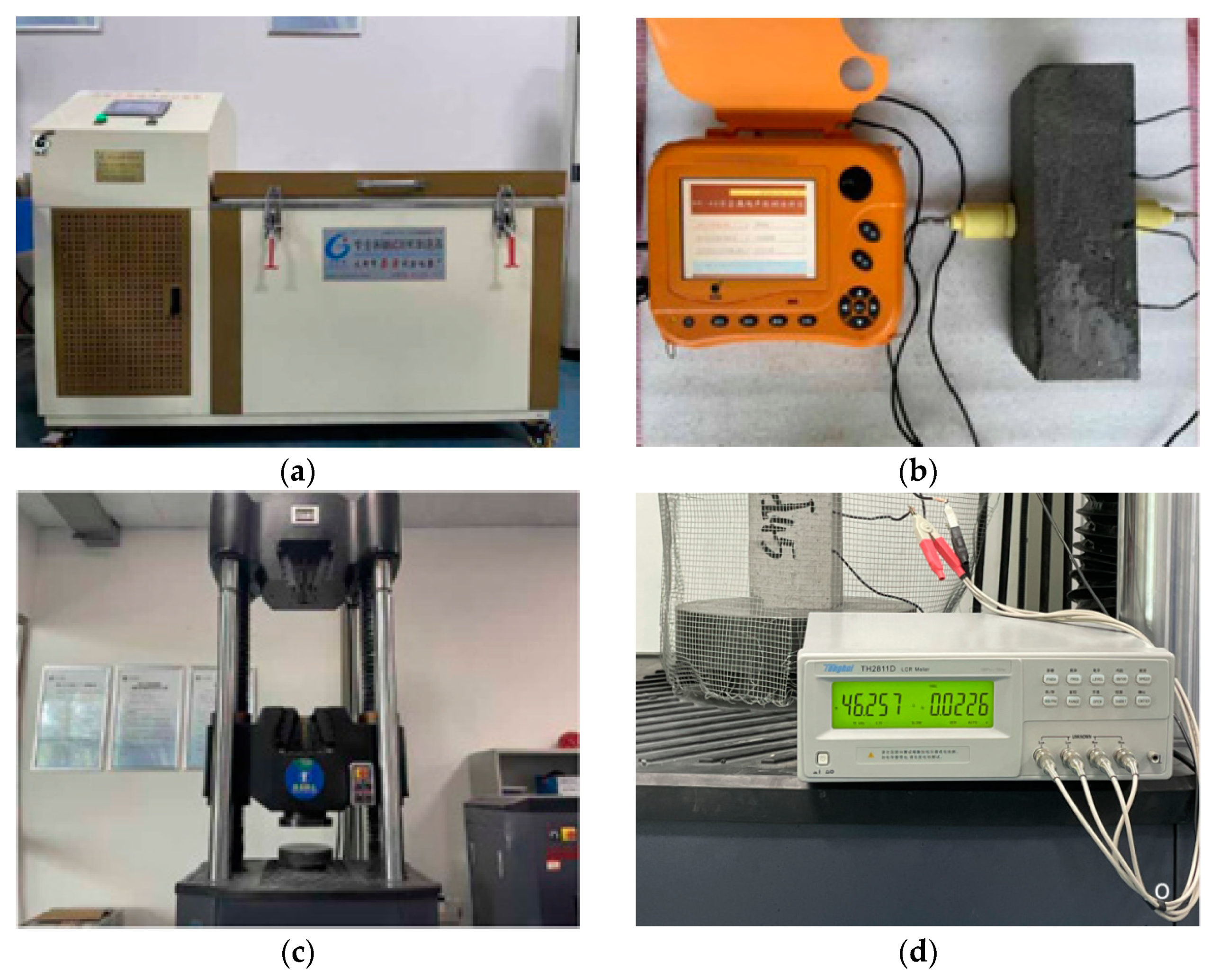
2.3. Testing Instruments

The instruments used in the research on the durability and pressure-sensitive properties of cement-based composites are as follows: the freeze-thaw cycle tests adopt the Gangyuan TDR-28 fast freeze-thaw cycle machine, the non-contact ultrasonic tests adopt the Kangkerui brand NM-4B non-metallic ultrasonic testing analyzer, MTS2000kN electro-hydraulic servo universal testing machine is used for the pressure tests and the pressure sensitive tests adopt the Tonghui brand TH2811D LCR digital bridge. The test equipment is shown in Figure 2.

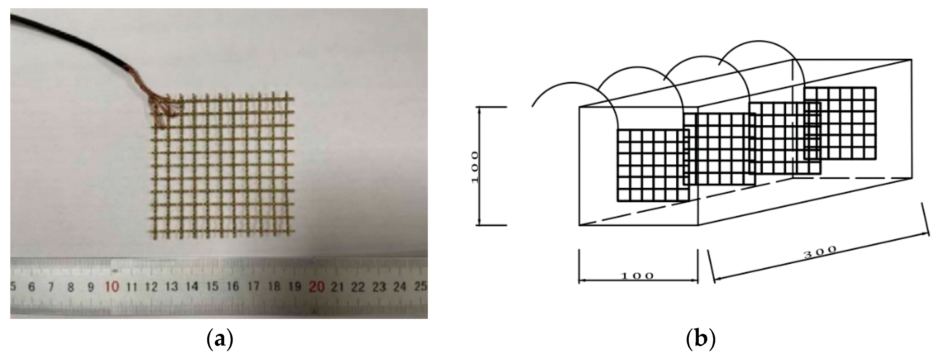
2.4. Sample Preparation

By referring to the standard for test methods of concrete physical and mechanical properties (GB/T 50081-2019) [24], 100 mm × 100 mm × 100 mm cube specimens were prepared, which were tested for their mechanical properties under the sulfate freeze-thaw cycle. For the pressure-sensitive tests under sulfate-freeze-thaw cycle conditions, a 70 mm × 70 mm copper mesh was used as the electrode. When preparing a 100 mm × 100 mm × 300 mm prismatic specimen, four electrodes were pre-buried inside the specimen. The embedding distance between the two adjacent electrodes was 60 mm. The size of the sample is shown in Figure 3.

2.5. Texting Methods

The salt freeze-thaw corrosion test of the carbon fiber iron tailings cement-based composites refers to the standard for test methods of long-term performance and durability of ordinary concrete (GB/T 50082-2009) [25]. The cubic and prismatic specimens are placed in a sodium sulfate solution with a mass fraction of 8%, and after several freeze-thaw cycles, the apparent morphology, mass loss, relative dynamic elastic modulus and degradation of mechanical properties of the specimens are tested.
According to the previous research results, the pressure-sensitive performance tests of cement-based composites mainly include the externally attached two-electrode method and the embedded four-electrode method [26]. In engineering practice, measuring the resistivity of cement-based composites does not require damage to the engineering structure, and the electrodes can be embedded in the structure for non-destructive testing, and the direct current four-electrode method can avoid polarization effects. Therefore, in this study, the 70 mm × 70 mm copper mesh was pre-embedded inside a 100 mm × 100 mm × 300 mm prismatic specimen as four parallel electrodes, and the electrodes were connected to external wires. Each group was tested with the same three specimens [27]. We connected the LCR digital bridge with the AC power supply (DC) and the four wires of the specimen, then we placed the specimen in the MTS pressure testing machine, loaded the specimen according to the displacement method. At this time, the data acquisition equipment was used to record the resistance change value of the specimen caused by the change in the applied load.

3. Experimental Results and Discussion of Durability Performance

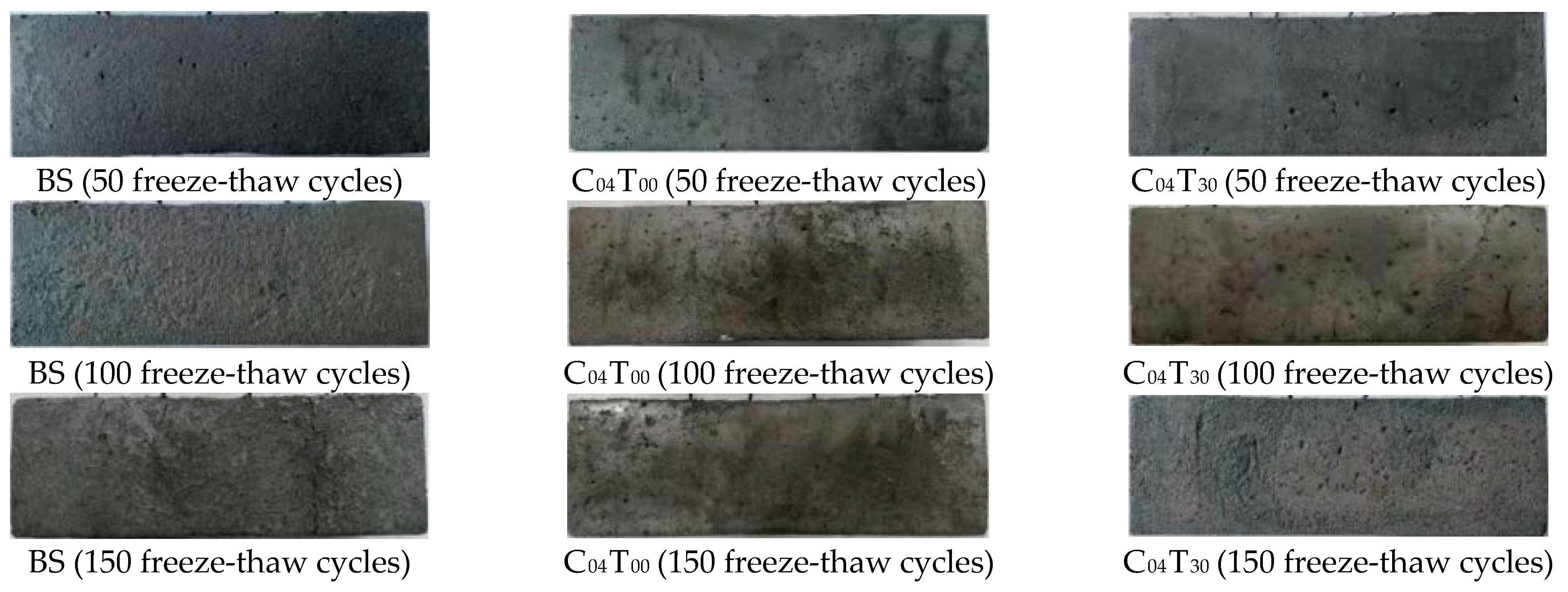
3.1. External Damage Analysis

According to the test results, the specimen prepared by the mix ratio of BS (benchmark specimen), C04T00 and C04T30 groups has a typical apparent damage pattern, so the epidermal damage analysis is carried out. Figure 4 shows the apparent morphology of the BS, C04T00 and C04T30 specimens after 50, 100 and 150 freeze-thaw cycles in 8% sodium sulfate solution. From the longitudinal comparison, it can be observed that with the increase in the number of freeze-thaw cycles, the apparent morphology of each group of specimens continues to deteriorate, the middle and corners of the specimens are gradually missing, and the surface holes and cracks gradually increase. The apparent damage of the C04T00 specimen was relatively less affected by the number of freeze-thaw cycles. After 100 freeze-thaw cycles, the color of the specimen turned yellow and the local color became darker. After 150 freeze-thaw cycles, salt particles were precipitated on the surface of the specimen. It can be observed from the lateral comparison that after 50 freeze-thaw cycles, the surface of the BS specimen becomes loose and a few holes appear, while the apparent damage of the C04T00 and C04T30 specimens is not obvious. After 100 freeze-thaw cycles, the apparent deterioration of the BS specimen was obvious. The C04T00 and C04T30 specimens still maintain a relatively complete form, a small number of holes appear and the color of the specimen began to turn yellow. After 150 freeze-thaw cycles, the BS specimen was loose in texture, with obvious overall deformation and transverse penetration cracks. The C04T00 specimen edges and corners appear to be missing, and the texture is relatively dense. The C04T30 specimen has obvious holes and obvious surface corrosion marks. By observing the apparent morphology of the specimen, it can be concluded that adding a certain proportion of carbon fiber and iron tailings can effectively inhibit the development of cracks and maintain the integrity of the apparent morphology of the specimen. However, the specimens mixed with iron tailings and carbon fiber at the same time showed obvious damage after 150 freeze-thaw cycles, compared with the specimens with single carbon fiber.
The formula for calculating the mass loss rate of a single specimen of cement-based composites under salt-freezing erosion is as follows:
Δ W n i = W 0 i W n i W 0 i × 100
where Δ W n i —the mass loss rate of the ith concrete specimen after N freeze-thaw cycles (%), W 0 i —the mass of the ith concrete specimen before the freeze-thaw cycle test (g); W n i —the mass of the ith concrete specimen after N freeze-thaw cycles (g). The formula for calculating the average mass loss rate of a set of specimens is as follows:
Δ W n = i = 1 3 Δ W n i 3 × 100
where Δ W n is the average mass loss rate of a set of concrete specimens after N freeze-thaw cycles (%). The prismatic specimens of each group with a mix ratio were weighed after 50, 100 and 150 freeze-thaw cycles in 8% sodium sulfate solution, and the average mass loss rate of each group of specimens was calculated, as shown in Figure 5. The analysis shows that after 50 freeze-thaw cycles, the mass loss rate of the BS specimen is 0.9%, while the mass loss rate of the specimens mixed with carbon fiber and iron tailings is negative. On the one hand, the salt solution penetrated into the interior of the specimen and formed crystalline expansion products, which increased the quality. On the other hand, the specimens mixed with carbon fiber and iron tailings did not produce obvious external damage at the beginning of the freeze-thaw cycle, so the quality increased after freeze-thawing. With the increase in the number of freeze-thaw cycles, the mass loss rate of specimens mixed with carbon fiber and iron tailings gradually turns from negative to positive. This is because the salt solution freezes inside the specimen to generate pressure, and at the same time, the expansion of salt crystals generates pressure, which causes the specimen to be destroyed under salt erosion, and the mass loss of the specimen increases gradually. After 100–150 freeze-thaw cycles, the mass loss rates of all specimens were positive. After 150 freeze-thaw cycles, the mass loss rate of BS specimens reached 5.75%, which was significantly greater than that of the other specimens. After the addition of carbon fiber and iron tailings, the compactness of the cement-based material can be improved, the salt solution penetrates into the inside of the specimen by a relatively small amount, the expansion pressure generated by freeze-thawing results in little damage to the interior of the specimen, and the quality loss rate of the specimen does not exceed 5%, of which the C04T30 specimen quality loss rate is the smallest, only 3.65%. With the increase in carbon fiber and iron tailing content, the mass loss rates of C04T45 and C06T00 specimens were 4.7% and 4.95%, respectively. This is due to the insufficient hydration reaction caused by the agglomeration of carbon fiber and iron tailings in the interior of cement-based material, so the excessive incorporation of carbon fibers and iron tailings did not play a role in improving the durability of cement-based materials.

3.2. Internal Damage Analysis

The formula for calculating the relative dynamic elastic modulus of a single specimen of cement-based composite material under salt freezing erosion is as follows:
P i = f n i 2 f 0 i 2 × 100
where P i —the relative dynamic elastic modulus of the ith concrete specimen after N freeze-thaw cycles (%), f n i —lateral fundamental frequency of the ith concrete specimen after N freeze-thaw cycles (Hz); f 0 i —lateral fundamental frequency of the ith concrete specimen before freeze-thaw cycles (Hz). The formula for calculating the average relative dynamic elastic modulus of a set of specimens is as follows:
P = 1 3 i = 1 3 P i
where P is the average relative dynamic elastic modulus of a group of concrete specimens after N freeze-thaw cycles (%). Prismatic specimens were prepared according to the mixing ratio of each group, and were subjected to 50, 100, and 150 freeze-thaw cycles in 8% sodium sulfate solution, respectively. The NM-4B non-metallic ultrasonic testing analyzer was used to measure the transverse fundamental frequency, and the relative dynamic elastic modulus of each group of specimens was calculated as shown in Figure 6. The analysis shows that the relative modulus of the BS specimen decreases with the increase in the number of freeze-thaw cycles. After 50 freeze-thaw cycles, the relative dynamic elastic modulus decreased significantly faster, indicating that the damage degree of the BS specimen increased. When the freeze-thaw cycle occurred 150 times, the relative dynamic elastic modulus of the BS specimen was 0.63, which almost reached the state of failure. The relative dynamic elastic modulus of the specimens mixed with carbon fiber and iron tailings sand generally showed a trend of first increasing and then decreasing after the freeze-thaw cycles. When the freeze-thaw cycle occurred about 50 times, its relative dynamic elastic modulus reached its peak value, and when the freeze-thaw cycle occurred 150 times, its relative dynamic elastic modulus was higher than 0.75, and its durability was significantly better than that of the BS specimen. This is because the fine powder of iron tailings sand reacts with calcium ions and silicon ions in the cement slurry to form hydration products, such as C-S-H gel, which causes the interior of the specimen to be continuously filled with crystals. Therefore, the relative dynamic elastic modulus of cement-based composites has an upward trend in the early stage of freeze-thaw cycles. With the progress of the freeze-thaw cycle, the expansion stress generated by the crystals increases continuously, and cracks appear inside the specimen. At this time, the tensioning and compaction effect of the carbon fiber and iron tailings in the cement colloidal caused the relative dynamic elastic modulus of the carbon fiber and iron tailings sample to decrease, but was still significantly higher than the relative dynamic elastic modulus of the BS specimen [28]. When the carbon fiber dosage reaches 0.4% and the substitution rate of iron tailings reaches 30%, the relative dynamic elastic modulus of the C04T30 specimen measured in the entire freeze-thaw cycle test is always the highest, indicating that its frost resistance is optimal. At the same time, it also shows that continuing to increase the content of carbon fiber and iron tailings does not make the cement-based composite material achieve a better antifreeze effect, which also indirectly confirms the analysis results of the quality loss rate.
The formula for calculating the loss rate of compressive strength of cement-based composite specimens under salt freezing erosion is as follows:
Δ f c = f c 0 f c n f c 0 × 100
where Δ f c —the loss rate of concrete compressive strength after N freeze-thaw cycles (%), f c 0 —the measured value of compressive strength of a set of concrete specimens for comparison (MPa); f c n —the measured value of compressive strength of a set of concrete specimens after N freeze-thaw cycles (MPa). The cube specimens with the mixing ratio of each group were tested with 50, 100, and 150 freeze-thaw cycles in 8% sodium sulfate solution, respectively. The MTS2000kN electro-hydraulic servo universal testing machine was used to measure the compressive strength of the specimens, and the compressive strength loss rate of each group of specimens was calculated, as shown in Figure 7. The analysis shows that the compressive strength of the BS specimen decreases with the increase in the number of freeze-thaw cycles. After 50 freeze-thaw cycles, the compressive strength loss rate further increased, indicating that the degree of deterioration of the specimen was more obvious. After 100 freeze-thaw cycles, the compressive strength loss rate gradually exceeded 25%, and the BS specimen changed from critical destruction to complete destruction. In contrast, due to the uneven stirring of carbon fiber or excessive incorporation of carbon fiber to cause agglomeration, and the entry of air bubbles to reduce the internal density of the specimen, the compressive strength loss rate of the specimens doped with carbon fiber alone in the early and middle periods of the freeze-thaw cycles is close to or greater than that of the BS specimens. After 150 freeze-thaw cycles, the carbon fiber exerted its crack resistance, so that the compressive strength loss rate of the single-doped carbon fiber specimens was smaller than that of the BS specimens. For the specimens that are mixed with carbon fiber and iron tailings at the same time, because iron tailings improve the compactness of cement-based composites, the internal pores become smaller so that the freeze resistance of the specimens can be improved. Therefore, even after 150 freeze-thaw cycles, the compressive strength loss rate of the double-doped carbon fiber and iron tailing specimens still does not exceed 25%.

4. Experimental Results and Discussion of Piezoelectric Performance

4.1. Stress-Resistivity Change Rate Correlation Evaluation

The four-electrode method was used to compare the pressure sensitivity of each group of specimens with different freeze-thaw cycles and the same mix ratio specimens without salt freezing erosion, and the correlation between the resistivity and compressive stress of the specimens was obtained. On this basis, the correlation law of resistivity change rate and stress change was analyzed. The calculation formulas of the resistivity, resistivity change rate and pressure sensitivity of the specimen are as follows [29]:
ρ = R × S L
R C R = Δ ρ ρ 0 = ρ t ρ 0 ρ 0
P S = 1 N 1 N R C R σ = 1 N 1 N Δ ρ / ρ 0 σ
where ρ —the resistivity of the specimen (Ω·cm), R —the resistance value of the specimen (Ω), S —the cross-sectional area of the electrode (cm2), L —the electrode spacing (cm), R C R —resistivity change rate (%); P S —pressure sensitivity (MPa−1). Each group of specimens was subjected to 150 freeze-thaw cycles in 8% sodium sulfate solution, and the compressive stress and resistance value of the specimens were measured by the MTS2000kN electro-hydraulic servo universal testing machine and TH2811D LCR digital bridge.
The correspondence relationship between the compressive stress and resistivity change rate of each group of specimens that did not undergo a freeze-thaw cycle is shown in Figure 8.
According to the analysis of Figure 8a, in the absence of a freeze-thaw cycle, the resistivity rate of change (RCR) in BS specimens and C02T00, C04T00 and C06T00 specimens doped with carbon fibers show a linear increasing trend with the increase in pressure load. The resistivity change rate of C02T00, C04T00 and C06T00 specimens mixed with carbon fibers reached 20.1%, 29.58% and 24.37% when crushed and destroyed, respectively. However, the resistivity change rate of the BS specimen without carbon fiber was only 2% at the time of failure. One must note that the pressure-sensitive performance of cement matrix composites is significantly improved by the incorporation of carbon fibers, and the resistance response of C04T00 specimens under load is the best when the carbon fiber dosage is 4%. At the same time, according to the corresponding stress value when the specimen is destroyed, it can be observed that the compressive strength of the specimen is not significantly improved by the single-doped carbon fiber. On the basis of adding 4% carbon fiber, iron tailings with substitution rates of 15%, 30% and 45% were added to prepare C04T15, C04T30 and C04T45 specimens, respectively. According to the analysis of Figure 8b, with the increase in pressure load, the resistivity change rate (RCR) of the specimens with single-doped carbon fiber or double-doped carbon fiber and iron tailings showed an obvious linear increasing trend. Since iron tailings improve the compactness of cement matrix composites, when the substitution rate of iron tailings sand is 30%, the resistivity change rate of C04T30 specimens during crushing failure reaches 33.79%. The magnitude of the change is greater than that of other groups of specimens, which is consistent with the research results of other scholars [28,30,31].
Using Origin software to fit the above data, the fitting curve is shown in Figure 8 and the results show that the compressive stress and resistivity change rate of each group of specimens that have not undergone freeze-thaw cycles are approximately linear in line with the linear relationship, such as formula (9).
R C R = a + b × σ
where R C R —resistivity change rate (%), σ —test compressive stress (MPa); a , b is the fitted curve constant. The fitting curve constants, correlation coefficients, and pressure sensitivities of each group of specimens that have not undergone a freeze-thaw cycle are shown in Table 6.
The analysis of the parameters in Table 6 shows that the BS group specimens were not mixed with carbon fiber and iron tailing sand, although the stress and resistivity rate of change were approximately linear, but their pressure sensitivity coefficient was only 0.000434, indicating that ordinary cement-based materials do not have good pressure sensitivity. The correlation coefficients of the fitting curves between the compressive stress and the resistivity change rate of the other groups of specimens are all above 0.9, and the pressure sensitivity coefficients are not less than 0.006213, indicating that there is a good correlation between the pressure and the resistivity change rate. The cement-based composites doped with carbon fiber and iron tailings sand have good pressure-sensitive properties. By comparing the pressure sensitivity coefficients of each group of cement matrix composite specimens, when single carbon fiber is mixed, the pressure sensitivity coefficient of the 4% carbon fiber dosage of the specimen is 0.006638, and the pressure sensitivity performance is the best. On this basis, when the substitution rate of iron tailings sand is 30%, the pressure sensitivity coefficient of the specimen is 0.007545, and the pressure sensitivity performance is further improved.
The corresponding relationship between the compressive stress and resistivity change rate of each group of specimens after 150 freeze-thaw cycles is shown in Figure 9.
According to the analysis of Figure 9, after 150 freeze-thaw cycles, the resistivity change rate of the BS specimen without carbon fiber and iron tailings sand does not change significantly with the increase in the compressive stress, while the resistivity change rate of other groups of specimens doped with carbon fiber or iron tailings sand becomes significantly larger with the increase in compressive stress, and the change trend decreases after the pressure load is greater than 10 MPa. The compressive strength that corresponds to the failure point of the cement matrix composite specimen is distributed between 30 MPa and 40 MPa, which is higher than that of the BS specimen, and compared with the failure to undergo freeze-thawing, the addition of carbon fiber or iron tailings sand can improve the compressive strength of the specimen in extreme environments. According to the analysis of Figure 9a, when the single-doped carbon fiber is 2%, 4% and 6%, the resistivity change rate of the specimen when it is crushed and destroyed reaches 14.85%, 19.95% and 17.36%, respectively. This indicates that the pressure sensitivity of the cement matrix composite material is improved by the incorporation of carbon fiber, and the resistance response of the C04T00 specimen in extreme environments is the best when the carbon fiber is 4%. According to the analysis of Figure 9b, by continuing to add iron tailings sand on the basis of adding carbon fiber, the compressive strength of the failure point of the specimen is improved. With the improvement of the substitution rate of iron tailing sand, the increase in resistivity change rate is not obvious and when the replacement rate of iron tailings sand is 30%, the resistivity change rate of the C04T30 specimen at the time of crushing failure reaches 25.34%, and the change amplitude is greater than that of the other specimens.
Using Origin software to fit the above data, the fitting curve is shown in Figure 9 and the results show that the compressive stress and resistivity change rate of each group of specimens after 150 freeze-thaw cycles approximately conform to the polynomial attenuation curve, such as formula (10).
R C R = a + b 1 × σ + b 2 × σ 2
where R C R —resistivity change rate (%), σ —test compressive stress (MPa); a , b 1 , b 2 is the fitted curve constant. The fitting curve constants, correlation coefficients, and pressure sensitivities of each group of specimens that have undergone 150 freeze-thaw cycles are shown in Table 7.
The analysis of the parameters in Table 7 shows that, after 150 freeze-thaw cycles, the specimens in the BS group were similar to those without freeze-thaw, and the pressure sensitivity coefficient was only 0.000377, which further indicated that ordinary cement-based materials do not have good pressure-sensitive properties. The correlation coefficients of the compressive stress and resistivity change rate fitting curves of the other groups of specimens are all above 0.9, and the pressure sensitivity coefficients are not less than 0.005426, indicating that the cement-based composites mixed with carbon fiber and iron tailings sand have good pressure-sensitive properties after extreme working conditions, and there is a good correlation between pressure and resistivity change rate. Among them, the pressure sensitivity coefficient of the specimen mixed with 4% carbon fiber and the substitution rate of 30% iron tailings sand is 0.007294, which has the best pressure sensitivity performance. Further comparison with the parameters of Table 6 shows that after the freeze-thaw cycle, the pressure sensitivity of each group of specimens has been attenuated, and the pressure sensitivity of the single-doped carbon fiber specimen is smaller than that of the specimens of re-doped carbon fiber and iron tailing sand [32,33].

4.2. Pressure Sensitivity Mechanism Analysis

For the cement-based composites with single-doped carbon fibers, when the amount of carbon fibers is low, the potential barrier between the conductive materials is relatively large, the relative permittivity is relatively small, and the tunneling effect is dominant compared with the capacitive effect, which is manifested as the uncoupled carbon fibers forming a conductive path through the tunnel transition effect. If one continues to increase the content of carbon fiber, the hydration of the cement matrix produces a free ion conductive medium and the carbon fibers in the cement matrix overlap each other to form a conductive path, so that the cement-based composite material exhibits good pressure-sensitive properties. When the amount of carbon fiber is mixed to reach the permeability threshold, the charges are greatly de-trapped through the tunneling transition and the capacitive effect is enhanced. Compared with the capacitive effect, the advantage of the tunneling effect is further reduced, and the amplitude of the resistance reduction is reduced, which is manifested by a decrease in pressure sensitivity. This indicates that the carbon fiber content increases, so that the resistivity of the specimen is reduced and once the penetration threshold is reached, the increase in carbon fiber will not make the resistivity change significantly [6]. When an appropriate amount of iron tailings sand is incorporated, the iron tailing sand aggregates to cause electrolytic conductivity enhancement, so that the current can be transmitted on the complete conductive path, and the pressure sensitivity of the specimen is more sensitive. Continuing to increase the amount of iron tailings sand will affect the conductive path and tunnel transition effect formed by carbon fiber overlap, and reduce the sensitivity of the cement matrix composites to compressive stress [33].
After the freeze-thaw cycle, cracks and holes are generated inside the cement matrix composite specimen, and there are more free ions in the pores. At the same time, the crack inside the specimen becomes smaller with the increase in pressure, and the distance of the conductive material is also reduced, causing the potential barrier between the carbon fibers to decrease. The decrease in resistivity caused by the reduction in free ions and fiber barriers is greater than the increase in resistivity caused by freeze-thaw damage. Therefore, when the pressure increases slightly, the resistivity of the cement-based composite material still has a good linear relationship with the pressure. With the increase in load, the crack damage inside the specimen is more serious, the distance between adjacent carbon fibers is far, and the aggregation effect of iron tailing sand is not enough to generate electron-hole transition. At the same time, the oxidation rate of iron tailings is accelerated under the corrosion of salt freezing, and the electrical conductivity is reduced due to rust. Therefore, the two together lead to a decrease in the pressure sensitivity of cement composites [17,34,35].

5. Conclusions

In this paper, the durability and pressure-sensitive properties of cement-based composites mixed with carbon fiber and iron tailing sands after undergoing freeze-thaw cycles were studied. The external damage of cement-based composites was analyzed from the apparent shape and mass loss of the specimen, and the internal damage was analyzed from the relative dynamic elastic modulus of the specimen and the deterioration of mechanical properties. The pressure sensitivity of cement matrix composites is quantitatively analyzed by the resistivity change rate and pressure sensitivity of the specimen. The conclusions are as follows:
(1)
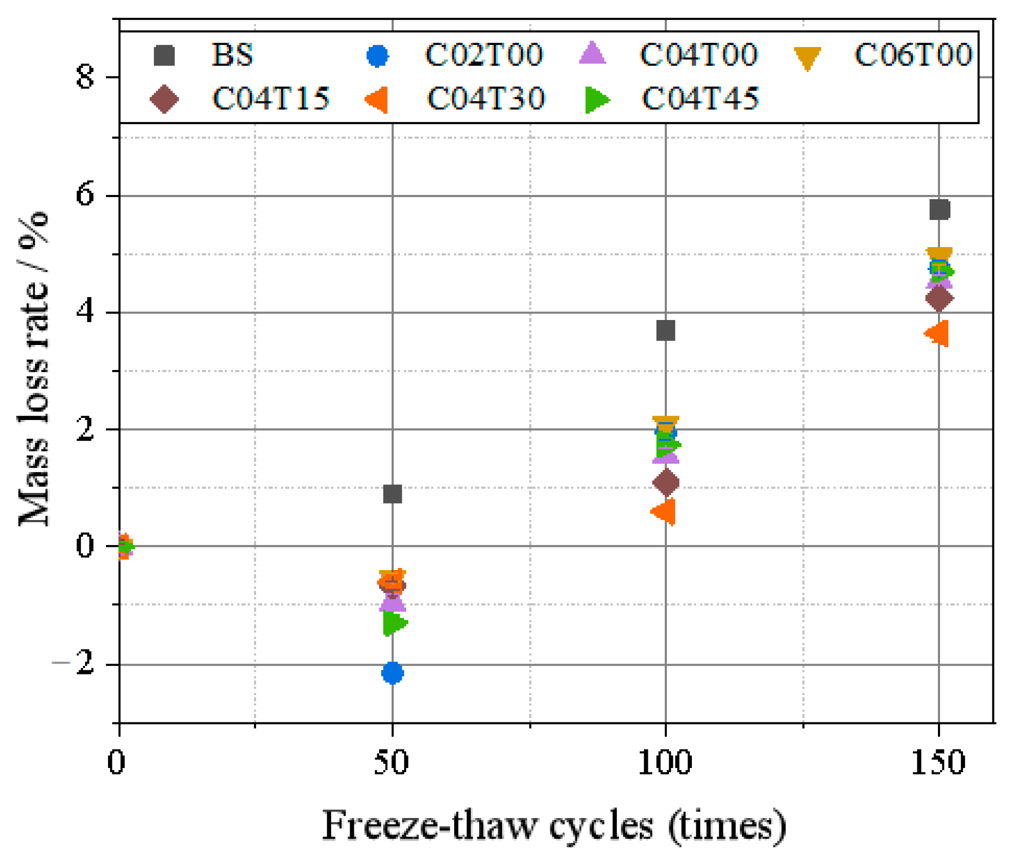
After 150 freeze-thaw cycles, compared with the specimens mixed with 0.4% carbon fiber and 30% substitution rate iron tailing sand, the apparent morphology of the specimens mixed with 0.4% carbon fiber remained more complete. By comparison, the C04T30 specimen with 0.4% carbon fiber and 30% substitution rate iron tailing sand at the same time had the smallest mass loss rate, which was only 3.65%. It shows that the addition of carbon fiber and iron tailing sand can improve the freeze-thaw resistance of cement-based composites.
(2)
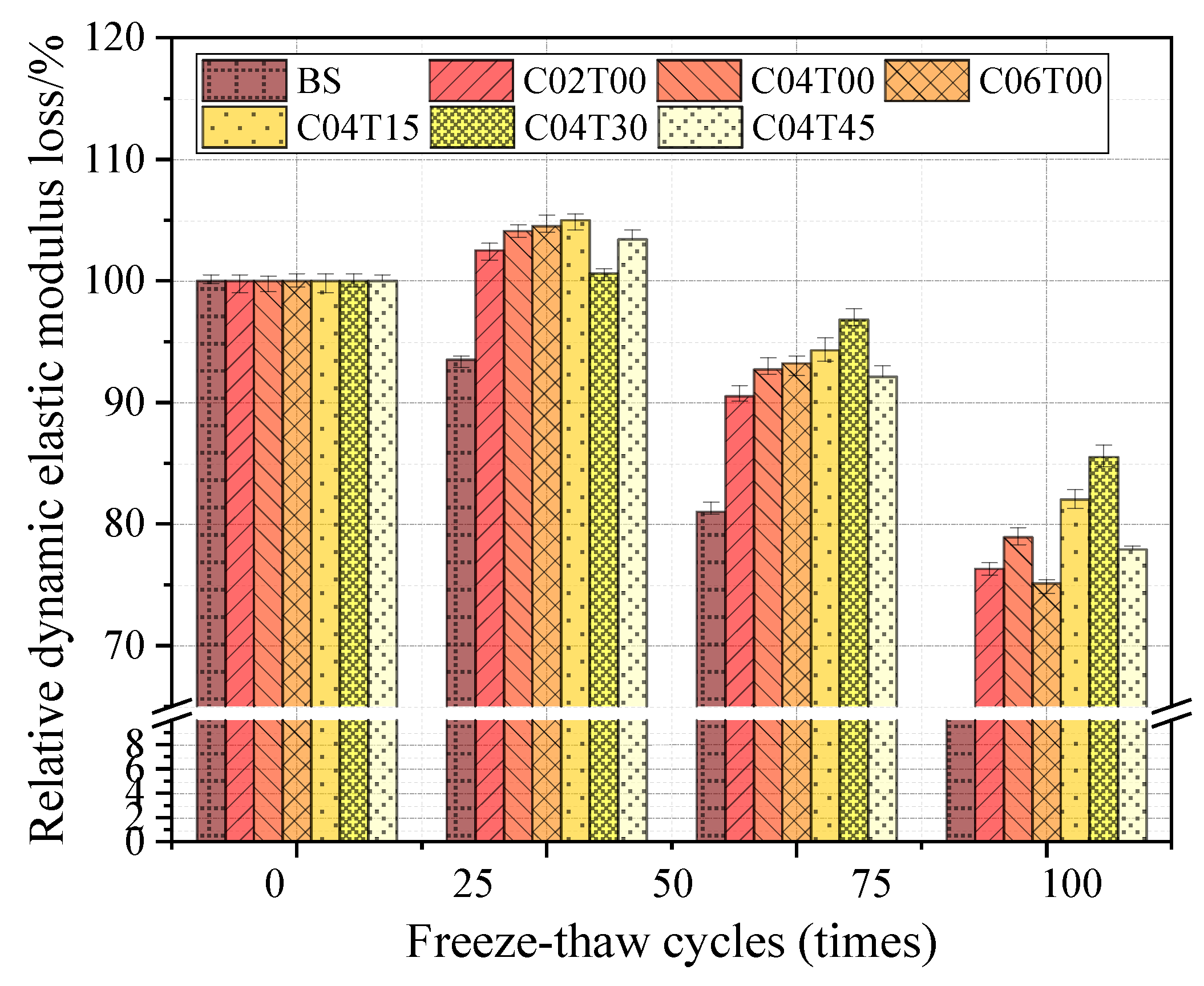
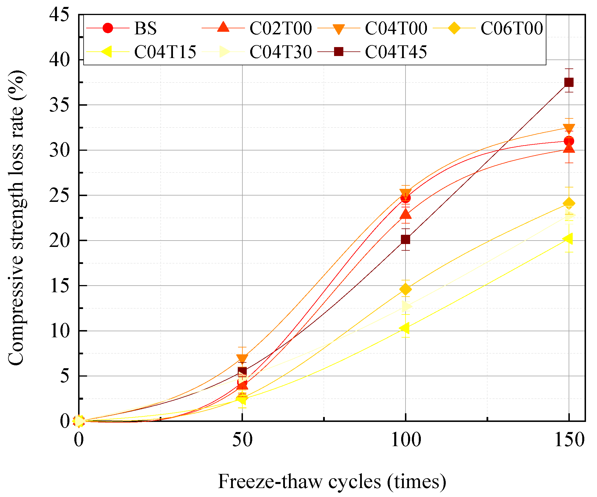
After 150 freeze-thaw cycles, the relative modulus of the BS specimen without carbon fiber and iron tailing sand was 0.63, the compressive strength loss rate exceeded 37.5%, and the specimen reached a destructive state. The relative dynamic elastic modulus of the C04T30 specimen mixed with 0.4% carbon fiber and 30% substitution rate iron tailing sand at the same time was 0.855, and the compressive strength loss rate was only 20.2%. It shows that the incorporation of carbon fiber and iron tailing sand can improve the erosion resistance of cement-based composites.
(3)
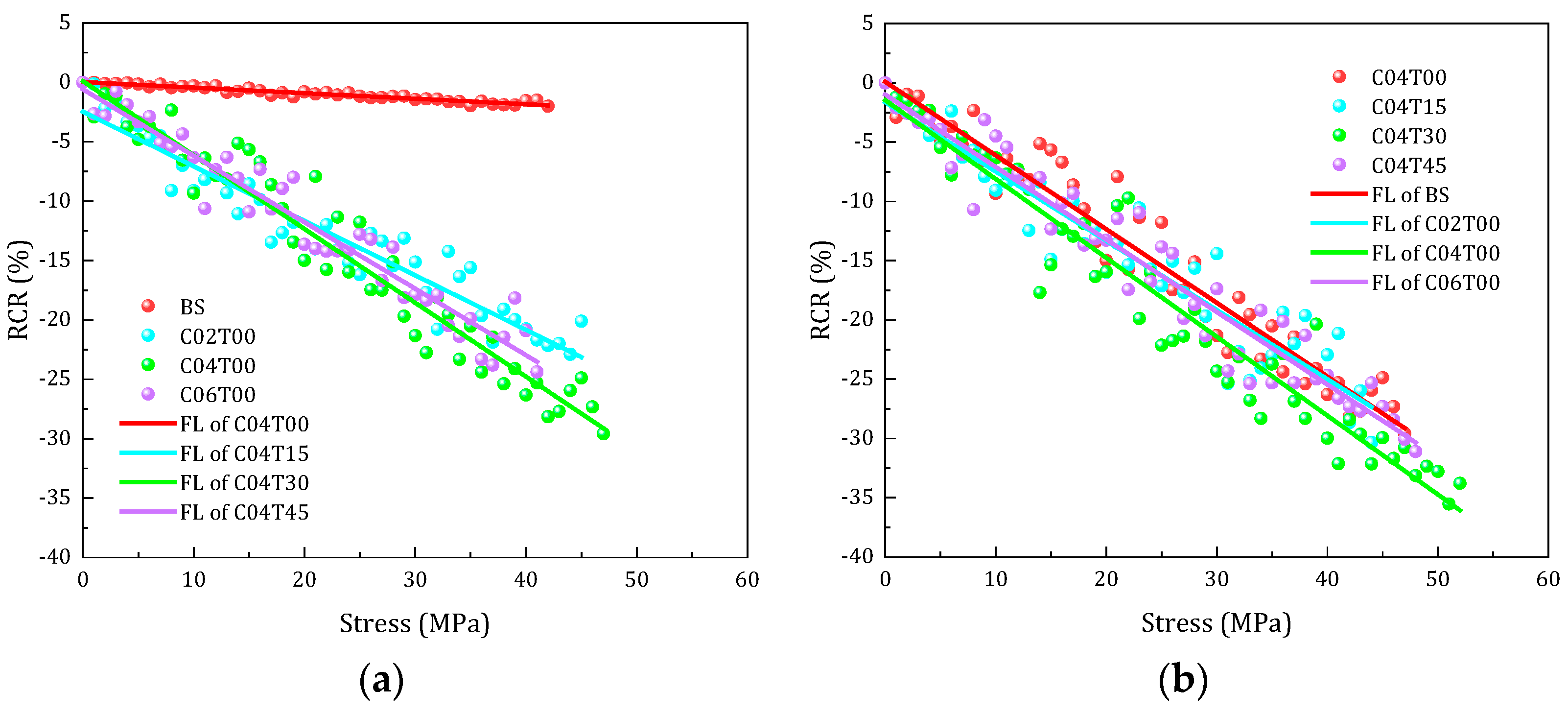
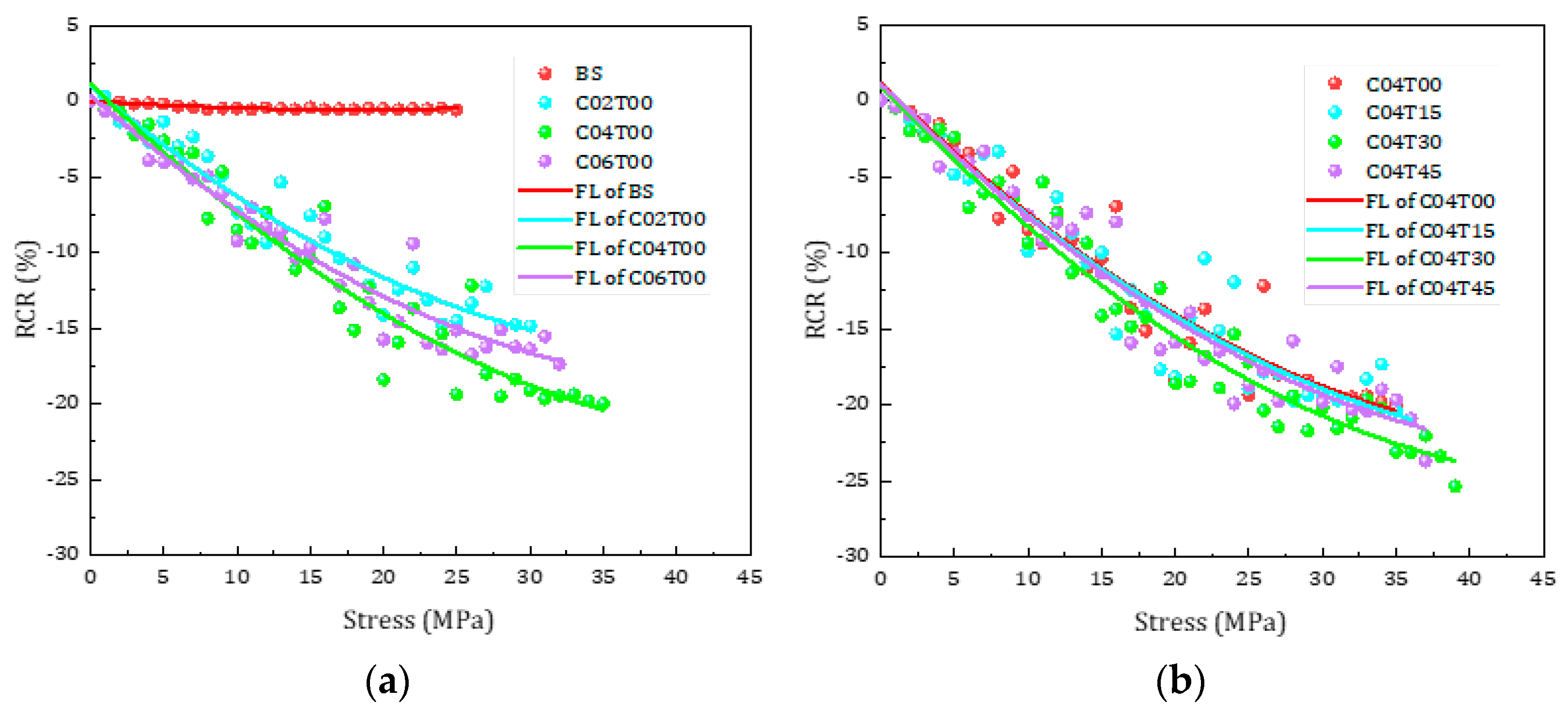
The compressive stress and resistivity change rate of each group of cement matrix composite specimens that did not undergo a freeze-thaw cycle were approximately in line with the linear attenuation relationship, and the correlation coefficients of the compressive stress and resistivity change rate fitting curves were above 0.9. The compressive stress and resistivity change rate of the cement matrix composite specimen that underwent 150 freeze-thaw cycles were approximately in line with the polynomial attenuation relationship, and its correlation coefficient was also above 0.9. The fitting results show that the correlation between resistivity change rate and compressive stress was high, and the rate of resistivity change can reflect the deterioration of structural mechanical properties after the freeze-thaw cycle.
(4)
After 150 freeze-thaw cycles, the pressure sensitivity coefficient of the cement-based composite specimen with 4% carbon fiber and 30% iron tailing sand substitution rate was 0.007294. Compared with the specimens of re-doped carbon fibers and iron tailing sands, the pressure sensitivity of the specimens of single-doped carbon fibers was less attenuated. It is explained by the fact that cement matrix composites mixed with carbon fiber and iron tailing sand have good pressure sensitivity, and cement matrix composites can be embedded as impedance sensors to monitor the health of engineering structures.

Author Contributions

Conceptualization, J.X. and S.W.; Data curation, J.B.; Formal analysis, J.X. and J.B.; Funding acquisition, J.X.; Investigation, J.B. and Y.L.; Methodology, J.X.; Project administration, J.X.; Resources, Y.L.; Software, Y.L.; Supervision, J.X.; Validation, X.Q.; Visualization, X.Q.; Writing—original draft, J.X.; Writing—review & editing, J.X. All authors have read and agreed to the published version of the manuscript.

Funding

This research was funded by the Key Research and Development Program of Shaanxi (grant number 2021SF-521).

Institutional Review Board Statement

Not applicable.

Informed Consent Statement

Not applicable.

Data Availability Statement

Not applicable.

Conflicts of Interest

The authors declare no conflict of interest.

References

  1. Wang, Y.; Zhao, X.; Zhu, D.; Du, J. Study on sensitivity of piezoresistivity and mechanism for cement-based composites with carbon fiber. Bull. Chin. Ceram. Soc. 2013, 9, 1817–1821. [Google Scholar] [CrossRef]
  2. Shan, G.; Zhen, P.; Xiaodong, L.; Dong, C. Tests on axial strength of circle CFST stub columns under marine atmosphere in cold region. Constr. Build. Mater. 2020, 230, 117073. [Google Scholar]
  3. Gao, S.; Guo, L.; Zhang, S.; Peng, Z. Performance degradation of circular thin-walled CFST stub columns in high-latitude offshore region. Thin-Walled Struct. 2020, 154, 106906. [Google Scholar] [CrossRef]
  4. Zhou, L.; Wang, X.; Liu, H. Experimental study of stress-strain curve of carbon fiber reinforced concrete. Eng. Mech. 2013, 30, 200–204+211. [Google Scholar] [CrossRef]
  5. Wang, T.; Xu, J.; Peng, G.; Meng, B. Durability test of carbon nanofiber reinforced concrete. Funct. Mater. 2019, 59, 11114–11121. [Google Scholar] [CrossRef]
  6. Azhari, F.; Banthia, N. Cement-based sensors with carbon fibers and carbon nanotubes for piezoresistive sensing. Cem. Concr. Compos. 2012, 34, 866–873. [Google Scholar] [CrossRef]
  7. Gao, S.; Cui, X.; Kang, S.; Ding, Y. Sustainable applications for utilizing molybdenum tailings in concrete. J. Clean. Prod. 2020, 266, 122020. [Google Scholar] [CrossRef]
  8. Tang, K.; Mao, X.; Xu, W.; Tang, X. Performance analysis of cement concrete with iron tailings sand as fine aggregate. Ind. Constr. 2019, 49, 153–157. [Google Scholar] [CrossRef]
  9. Zhang, W.; Gu, X.; Qiu, J.; Liu, J.; Zhao, Y.; Li, X. Effects of iron ore tailings on the compressive strength and permeability of ultra-high performance concrete. Constr. Build. Mater. 2020, 260, 119917. [Google Scholar] [CrossRef]
  10. Wang, X.; Zhang, S.; Bao, W.; Qi, H. Experimental study on durability of tailings concrete. Concrete 2020, 4, 93–97. [Google Scholar] [CrossRef]
  11. Barroqueiro, T.; Da Silva, P.R.; De Brito, J. High-Performance Self-Compacting Concrete with Recycled aggregates from the precast industry: Durability assessment. Buildings 2020, 10, 113. [Google Scholar] [CrossRef]
  12. Ullah, S.; Yang, C.; Cao, L.; Wang, P.; Chai, Q.; Li, Y.; Wang, L.; Dong, Z.; Lushinga, N.; Zhang, B. Materials design and performance improvement of conductive asphalt concrete incorporating carbon fiber and iron tailings. Constr. Build. Mater. 2021, 303, 124446. [Google Scholar] [CrossRef]
  13. Liu, Y.; Hao, W.; He, W.; Meng, X.; Shen, Y.; Du, T.; Wang, H. Influence of dolomite rock powder and iron tailings powder on the electrical resistivity strength and microstructure of cement pastes and concrete. Coatings 2022, 12, 95. [Google Scholar] [CrossRef]
  14. Zhu, H.; Yu, J.; Zhang, J. A summary review and advantages of vibration-based damage identification methods in structural health monitoring. Eng. Mech. 2011, 28, 1–11. [Google Scholar] [CrossRef]
  15. Mendes, S.E.; Oliveira, R.L.; Cremonez, C.; Pereira, E.; Pereira, E.; Medeiros-Junior, R.A. Electrical resistivity as a durability parameter for concrete design: Experimental data versus estimation by mathematical model. Constr. Build. Mater. 2018, 192, 610–620. [Google Scholar] [CrossRef]
  16. Allam, H.; Duplan, F.; Clerc, J.-P.; Amziane, S.; Burtschell, Y. About electrical resistivity variation during drying and improvement of the sensing behavior of carbon fiber-reinforced smart concrete. Constr. Build. Mater. 2020, 264, 120699. [Google Scholar] [CrossRef]
  17. Song, J.; Zhang, Y.; Zhang, R.; Hao, T. Research on relation of anti-chloride permeability and concrete resistivity based on DC-step input. Concrete 2020, 3, 59–62. [Google Scholar] [CrossRef]
  18. Robles, K.P.V.; Yee, J.-J.; Kee, S.-H. Electrical resistivity measurements for nondestructive evaluation of chloride-induced deterioration of reinforced concrete—A review. Materials 2022, 15, 2725. [Google Scholar] [CrossRef]
  19. Wang, J.-H.; Sun, H.-X.; Dong, Y.-G.; Cheng, Z.; Liu, W. Effects of the water/cement ratio on the properties of 3-3 type cement-based piezoelectric composites. Materials 2022, 15, 2760. [Google Scholar] [CrossRef] [PubMed]
  20. Le, T.-C.; Ho, D.-D.; Huynh, T.-C. Anchor force monitoring using impedance technique with single-point mount lead-zirconate-titanate interface: A feasibility study. Buildings 2021, 11, 382. [Google Scholar] [CrossRef]
  21. Le, T.-C.; Phan, T.T.V.; Nguyen, T.-H.; Ho, D.-D.; Huynh, T.-C. A low-cost prestress monitoring method for post-tensioned RC beam using piezoelectric-based smart strand. Buildings 2021, 11, 431. [Google Scholar] [CrossRef]
  22. Ministry of Housing and Urban-Rural Construction of the People’s Republic of China. Standard for Technical Requirements and Test Method of Sand and Crushed Stone (or Gravel) for Ordinary Concrete (JGJ52-2006); China Architecture & Building Press: Beijing, China, 2006. [Google Scholar]
  23. Ministry of Housing and Urban-Rural Construction of the People’s Republic of China. Standard for Test Methods of Performance on Ordinary Fresh Concrete (GB/T 50080-2016); China Architecture & Building Press: Beijing, China, 2016. [Google Scholar]
  24. Ministry of Housing and Urban-Rural Construction of the People’s Republic of China. Standard for Test Methods of Concrete Physical and Mechanical Properties (GB/T 50081-2019); China Architecture & Building Press: Beijing, China, 2019. [Google Scholar]
  25. Ministry of Housing and Urban-Rural Construction of the People’s Republic of China. Standard for Test Methods of Long-Term Performance and Durability of Ordinary Concrete (GB/T 50082-2009); China Architecture & Building Press: Beijing, China, 2009. [Google Scholar]
  26. Qian, J.; Xu, S.; Li, M.; Wang, L. The measurement and application of resistivity for concrete. J. Shandong Univ. Sci. Technol. 2010, 29, 37–42. [Google Scholar] [CrossRef]
  27. Yin, T.; Xu, J.; Wang, Y.; Liu, L. Increasing self-sensing capability of carbon nanotubes cement-based materials by simultaneous addition of Ni nanofibers with low content. Constr. Build. Mater. 2020, 254, 119306. [Google Scholar] [CrossRef]
  28. Li, Y.; Wang, S.; Xu, J.; Bai, J.; Quan, X.; Xu, W. Durability and piezoresistivity of self-sensing cement mortar under sulphate freeze-thaw cycles. Bull. Chin. Ceram. Soc. 2022, 1. [Google Scholar] [CrossRef]
  29. Nalon, G.H.; Ribeiro, J.C.L.; de Araújo, E.N.D.; Pedroti, L.G.; de Carvalho, J.M.F.; Santos, R.F.; Aparecido-Ferreira, A. Effect of different kinds of carbon black nanoparticles on the piezoresistive and mechanical properties of cement-based composites. J. Build. Eng. 2020, 32, 101724. [Google Scholar] [CrossRef]
  30. Cholker, A.K.; Tantray, M.A. Micro carbon fiber based concrete as a strain-damage sensing material. Mater. Today Proc. 2019, 19, 152–157. [Google Scholar] [CrossRef]
  31. Wang, L.; Aslani, F. Piezoresistivity performance of cementitious composites containing activated carbon powder, nano zinc oxide and carbon fibre. Constr. Build. Mater. 2021, 278, 122375. [Google Scholar] [CrossRef]
  32. Lehner, P.; Konečný, P.; Katzer, J. Electrical resistivity and strength parameters of prismatic mortar samples based on standardized sand and lunar aggregate simulant. Buildings 2022, 12, 423. [Google Scholar] [CrossRef]
  33. Baeza, F.J.; Galao, O.; Vegas, I.; Cano, M.; Garcés, P. Influence of recycled slag aggregates on the conductivity and strain sensing capacity of carbon fiber reinforced cement mortars. Constr. Build. Mater. 2018, 184, 311–319. [Google Scholar] [CrossRef]
  34. Ge, Y.; Liu, S. Research progress on characteristics of carbon fiber conductive concrete. Bull. Chin. Ceram. Soc. 2019. [Google Scholar] [CrossRef]
  35. Belli, A.; Mobili, A.; Bellezze, T.; Tittarelli, F. Commercial and recycled carbon/steel fibers for fiber-reinforced cement mortars with high electrical conductivity. Cem. Concr. Compos. 2020, 109, 103569. [Google Scholar] [CrossRef]
Figure 1. The grain gradation curve of iron ore tailings.
Buildings 12 01150 g001
Figure 2. The test instruments: (a) freeze-thaw testing chamber; (b) ultrasonic detector; (c) MTS pressure testing machine; (d) LCR digital bridge.
Buildings 12 01150 g002
Figure 3. Dimensional parameters of specimen and electrode: (a) size of copper mesh; (b) size of specimen.
Buildings 12 01150 g003
Figure 4. Apparent failure morphology of cement-based composites under freeze-thaw cycles.
Buildings 12 01150 g004
Figure 5. Mass loss rate of cement-based composites under freeze-thaw cycles.
Buildings 12 01150 g005
Figure 6. Relative dynamic elastic modulus of cement-based composites under freeze-thaw cycles.
Buildings 12 01150 g006
Figure 7. Compressive strength loss rate of cement-based composites under freeze-thaw cycles.
Buildings 12 01150 g007
Figure 8. Stress–RCR fitting curves of cement-based composites before freeze-thaw cycles. (a) Stress–RCR curves of BC, C02T00, C04T00, C06T00; (b) stress–RCR curves of C04T00, C04T15, C04T30, C04T45.
Buildings 12 01150 g008
Figure 9. Stress–RCR fitting curves of cement-based composites under 150 freeze-thaw cycles. (a) Stress–RCR curves of BC, C02T00, C04T00, C06T00, (b) stress-RCR curves of C04T00, C04T15, C04T30, C04T45.
Buildings 12 01150 g009
Table 1. Chemical composition of cement and iron tailings.
Chemical CompositionCOMgAlSiSKCaFeTi
Cement (%)4.1239.080.741.546.111.100.5345.840.930.01
IOT (%)-56.496.958.3817.46-3.021.685.280.74
Table 2. Chemical composition of quartz sand.
Chemical
Composition
Na2OMgOFe2O3Al2O3CaOSiO2
Quartz (%)1.2 ± 0.250.68 ± 0.120.91 ± 0.321.1 ± 0.30.27 ± 0.1375–96
Table 3. Main performance indicators of cement.
Water Requirement of Normal Consistency
(%)
Initial Setting Time
(min)
Final Setting Time
(min)
Fineness
(μm)
StabilityFlexural Strength
(MPa)
Compressive Strength
(MPa)
3 d28 d3 d28 d
2816028040Qualified5.26.819.542.5
Table 4. Basic parameters of carbon fiber.
Length
(mm)
Diameter
(μm)
Density
(g/cm3)
Carbon Content
(%)
Tensile Strength
(MPa)
Tensile Modulus
(GPa)
Resistivity
(10−3 Ω·cm)
571.75≥9535302281.0–1.6
Table 5. The mix design of cement-based piezoelectric composites.
Serial
No
Sample
No
Water
(kg/m3)
Cement
(kg/m3)
Silica
Fume
(kg/m3)
Fine Aggregate
/kg/m3
Replace-ment Rate of IOT (%)Carbon
Fiber
(kg/m3)
Replace-ment Rate of CF (%)
Silica SandIOT
1BS242550556050000
2C02T0024255055605003.500.2
3C04T0024255055605007.000.4
4C06T00242550556050010.500.6
5C04T1524255055514.2590.75157.000.4
6C04T3024255055423.50181.50307.000.4
7C04T4524255055332.75272.25457.000.4
Table 6. Fitting curve parameters of cement-based composites before freeze-thaw cycles.
ParameterBSC02T00C04T00C06T00C04T15C04T30C04T45
a0.02368−2.476720.0944−0.58481−1.63942−1.45606−0.98392
b−0.04662−0.45898−0.62169−0.55953−0.584−0.66546−0.6116
R20.928060.917950.944760.941840.908960.937910.94215
PS0.0004340.0062130.0066380.0065320.0071590.0075450.007229
Table 7. Fitting curve parameters of cement-based composites under 150 freeze-thaw cycles.
ParameterBSC02T00C04T00C06T00C04T15C04T30C04T45
a0.006240.997181.161820.392160.922970.969921.12923
b1−0.06364−0.82444−0.95198−0.85845−0.93611−1.02612−0.97451
b20.001780.009610.00960.00970.009150.010120.00977
R20.867350.933670.927950.933250.906590.953820.94295
PS0.0003770.0054260.0065030.0064970.0066730.0072940.006708
Publisher’s Note: MDPI stays neutral with regard to jurisdictional claims in published maps and institutional affiliations.

