Article

The Effect of the Bearing Width on the Buckling Capacity of Partially Loaded CLT Member

1
Research Institute of Wood Industry, Chinese Academy of Forestry, Beijing 100090, China
2
School of Civil Engineering, Harbin Institute of Technology, Harbin 150090, China
3
Faculty of Architecture, Civil and Transportation Engineering, Beijing University of Technology, Beijing 100124, China
*
Author to whom correspondence should be addressed.
Buildings 2022, 12(1), 84; https://doi.org/10.3390/buildings12010084
Submission received: 14 December 2021 / Revised: 11 January 2022 / Accepted: 14 January 2022 / Published: 17 January 2022
(This article belongs to the Special Issue Advances in Building Materials)

Abstract

:
The calculation method for buckling capacity of cross-laminated timber (CLT) under axial load with one-way members has been investigated and incorporated into design codes worldwide. However, the load may only be applied to a part of the CLT members. In this case, the available calculation method for buckling capacity is not applicable. To solve this problem, a 3D numerical model was developed to study the buckling behavior of axially loaded CLT members. After being validated by comparison with experimental results, the model was used to investigate the buckling capacity of axially loaded CLT members with different aspect ratios and bearing length ratios. The CLT members all consisted of three layers. The thickness of the CLT members was 105 mm, the width ranged from 300 mm to 2100 mm, and the height ranged from 1400 mm to 3500 mm. It was found that the unloaded part of CLT served as constraints to the loaded part. The longer the unloaded part, the stronger the constraint was. The buckling capacity increased with the increase in bearing length ratios. An equivalent width method (EWM) was proposed; i.e., the partially loaded CLT member was replaced by a fully loaded member with an equivalent width, which can be determined by the proposed formulas. It was found that the proposed calculation method is reliable and simple to apply. This study supplies the missing calculation method for the buckling behavior of partially loaded CLT members and helps to promote the engineering application of CLT members.

1. Introduction

Cross-laminated timber (CLT) is an innovative engineered wood product consisting of several layers of boards stacked crosswise and glued together [1]. CLT is designed to make the best use of low-grade wood; it has the advantage of high load-bearing capacity, large panel size, good dimensional stability, and good environmental performance [2]. CLT has been successfully applied in multi-story and high-rise timber buildings [3]. The calculation of the load-carrying capacity of CLT members is of vital importance to ensure the safety and reliability of CLT buildings. Additionally, the calculation method for buckling capacity of CLT members in compression is one of the most important topics.
Up to now, there are some product standards for CLT manufacturing. CLT manufactured by ANSI/APA PRG320-2017 [4] is generally made of dimension lumbers. CLT manufactured by BS EN 16351-2015 [5] is generally made of European strength-graded structural timbers. Additionally, CLT manufactured by LY/T 3039-2018 [6] is generally made of graded sawn timber by LY/T 2383 [7]. In the case of greater bearing capacity, structural composite lumber can also be used as lamination.
As shown in Figure 1, if the axially loaded CLT member is constrained on two opposite sides only, it is a one-way member. If the axially loaded CLT member is constrained on three or all four sides, it is a two-way member.
Few studies that have addressed the buckling behavior of CLT members as a one-way member can be found in the literature. Nakajima et al. [8] conducted a series of buckling tests on full-size CLT members; it was found that the formulas given in the Japanese Building Code provided conservative results. Pina et al. [9] studied the influence of the number of layers and openings on the buckling capacity of CLT members via a multi-scale finite element model. Perret et al. [10] introduced the Ayrton–Perry approach for buckling of a column with imperfections by adding the shear strength criterion, and the effect of creep on the buckling capacity was investigated. Huo et al. [11] proposed formulas for calculating the stability coefficient applicable to CLT members based on the available formulas for general timber members by regressing the material parameters and using the effective moment of inertia and section areas. Recently, Huang et al. [12] investigated the behavior of CLT members under combined out-of-plane bending and compression by experiment, and an analytical model taking the rolling shear effects into account to predict the load-carry capacity of compression-bending CLT members was developed.
For two-way members, Thiel and Krenn (2016) [13] investigated the buckling behavior of CLT members via theoretical and finite element methods. It was found that the crosswise layups and the shear flexibility due to the rolling shear modulus have a strong influence on the buckling capacity. In some boundary conditions and dimensions, the two-way behavior must be considered. Perret et al., 2016 [14,15], extended the bending–gradient theory to linear buckling analysis and applied it to the case of two-way rectangular CLT members.
To the knowledge of the authors, the available calculation methods for the buckling capacity (or the stability coefficient) of axially loaded CLT members in worldwide design codes are only applicable to one-way CLT members. The calculation method for the stability coefficient of axially loaded CLT members as one-way members has been incorporated into the design codes of several countries. In CSA O86-14 [16], the same formulas with other wood products were adopted for CLT; however, the slenderness ratio was calculated by only using the radius of gyration and section area of the longitudinal layers. The equations for calculating the stability coefficient of CLT members in axial compression stipulated in NDS-2018 [17] are nearly the same as the equations for other wood products. The difference is that the critical buckling stress is calculated using the “apparent bending stiffness” to consider the shear deformation in CLT members. Eurocode 5 [18] is still under revision. The equations for the stability coefficient of CLT members in axial compression proposed by Thiel et al. [19] are consistent in form with the equations for other products in the current Eurocode 5 [18]. Under the same principle, the equations for the stability coefficient of axially loaded CLT members have been proposed in the Austrian and Swedish CLT technical manuals [20,21]. The design method for axially loaded CLT members is also given in the Japanese Building Code. The calculation formulas are the same as that of other wood products. However, an additional factor of 0.75 is applied to the calculated buckling capacity.
It could be found that the currently available calculation methods for buckling capacity of axially loaded CLT members are only applicable to CLT members with compressive loads evenly and axially imposed on the two opposite sides, henceforth referred to as fully loaded CLT members. However, in some cases, the compressive loads may be imposed only on part of the wall, henceforth referred to as partially loaded CLT members, as shown in Figure 2. A common example for this case is a beam resting on the CLT wall (Figure 2a,b). In these cases, the bearing length may have an impact on the buckling capacity of CLT members. Nevertheless, this fact has not been investigated so far.
Thus, in this study, a numerical model was developed to investigate the effect of bearing length on the buckling capacity of partially loaded CLT members. The model was first validated by comparison with experimental results, and then the numerical model was used to study the influence of the bearing length on the buckling capacity of axially loaded CLT members. An effective width method was proposed to replace the partially loaded CLT members with a fully loaded member with an equivalent width. The calculation method for the equivalent width was proposed.
This study supplies the missing calculation method for the buckling capacity of axially and partially loaded CLT members and helps to promote the engineering application of CLT members.

2. Methods

2.1. The Numerical Model

The CLT member was modeled using Abaqus software. As an example, a finite element (FE) model is shown in Figure 3. The longitudinal and transverse layers of the CLT member were modeled with the 3-dimensional, 8-node, linear brick elements (C3D8R). Mesh sensitivity analysis was carried out to find a good mesh size. Finally, the CLT member was more densely meshed in the loading area along the width direction, and there were two elements in the thickness direction for each layer. The number of elements was between 3936 and 83,160, depending on the dimension of the CLT member. Glue line failure before failure of wood is not allowed in qualified CLT members, according to the product standard. Additionally, no slip between layers before buckling was observed by the authors or reported in the literature. The slip between layers was neglected in the FE model, and layers were bonded together via the tie interaction.
To model the simply supported boundary conditions at the upper and lower edge, as shown in Figure 3, a reference point was set at the lower and upper end of the member, respectively. The CLT member was axially loaded at the upper reference point, which was coupled to the corresponding area of the CLT member, and the translational degrees of freedom and the z and y-axis rotational degrees of freedom were constrained at the lower reference point, which was also coupled to the corresponding panel side.
In this study, wood was modeled as an orthotropic material. Hill’s potential [22] was used to model the strength differences in the parallel and perpendicular to the grain directions by specifying a reference yield stress and defining a set of yield ratios separately. The large displacements and large strains were realized by considering the material nonlinearity and geometric nonlinearity.
The material properties of Canadian hemlock (Tsuga canadensis (L.) Carrière) were used in this study. The modulus of elasticity parallel to the grain E, compression strengths parallel and perpendicular to the grain, and shear strength parallel to grain were extracted from wood handbook [23]. The modulus of elasticity perpendicular to the grain was assumed to be E/30, and the shear modulus was assumed to be E/16 as in PRG-320 [4]. The rolling shear strength and modulus were from the test results of Ruan et al. [24]. The material properties used in this study are presented in Table 1.
To obtain the buckling capacity of CLT members, displacement-controlled nonlinear post buckling analysis was carried out. Load displacement curves were obtained, and the maximum load was taken as the buckling capacity of a specimen. It should be noted that both long and shorter columns were analyzed; thus the eigenvalue buckling analysis method was not adopted.

2.2. Parametric Study

As shown in Figure 4, to investigate the effect of bearing length on the buckling capacity of CLT members, CLT members with different bearing lengths and aspect ratios were modeled. In these models, the modulus of elasticity parallel to the grain was 8273 MPa, and the corresponding moduli of elasticity perpendicular to the grain and shear modulus parallel to the grain were calculated according to the relationship listed in Table 1. The CLT members all consisted of three layers. The width of CLT members, denoted as b, ranged from 300 mm to 2100 mm, and the height of CLT members, denoted as h, ranged from 1400 mm to 3500 mm. As stated before, the slenderness ratio of CLT members was modified in some design codes; in this study, the general slenderness ratio λ was used,
λ = h i
where h is the height of the CLT member and i is the least radius of gyration of the cross-section. The slenderness ratios ranged from 46 to 115. The load was applied to the CLT members and the bearing length was denoted as bre.

3. Results and Discussion

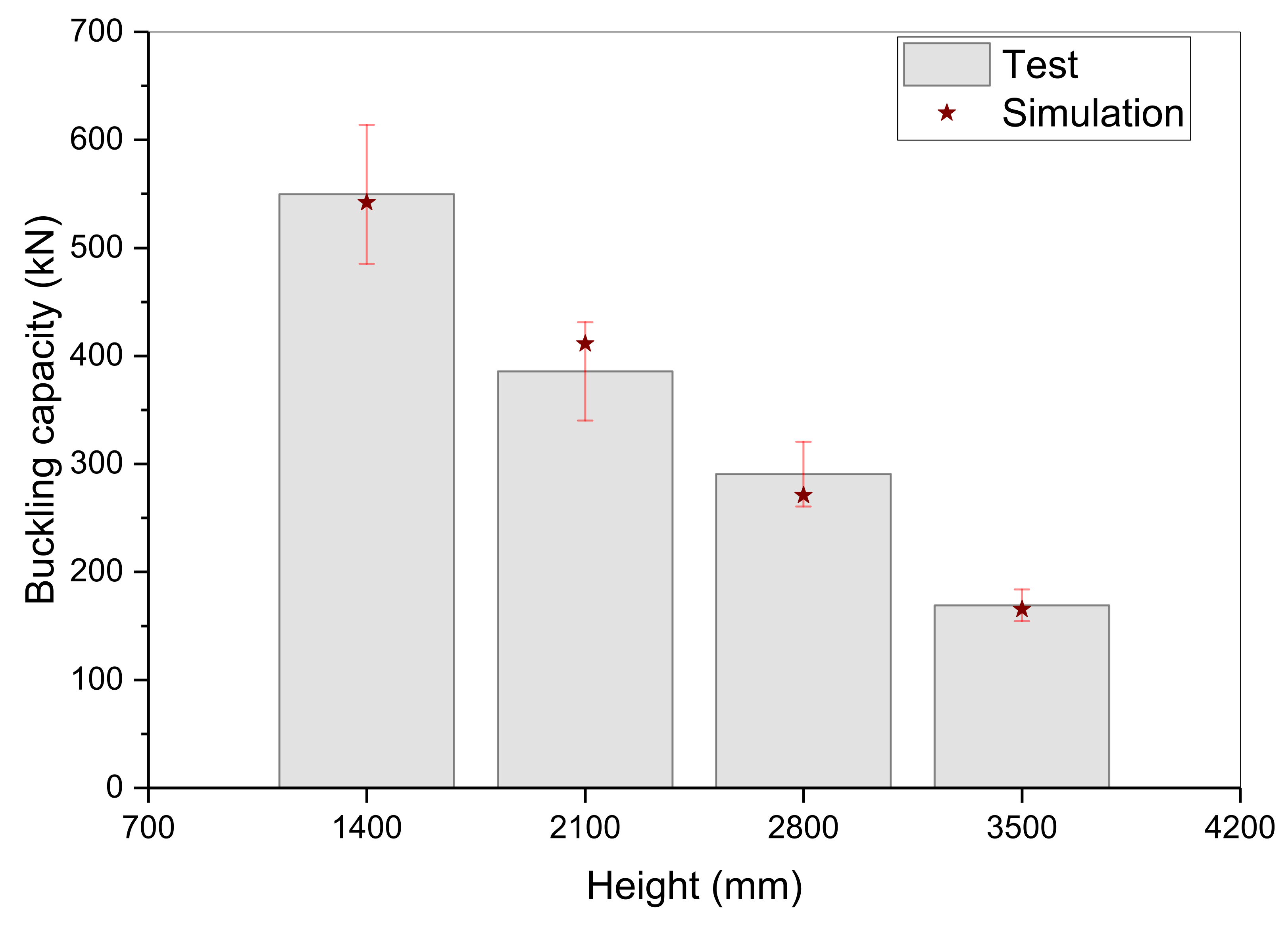
3.1. Model Validation

Huo et al. [11] measured the buckling capacity of CLT members made of Canadian hemlock. The test results were used to validate the proposed numerical model. As listed in Table 2, Huo et al. [11] tested four groups of CLT members with different slenderness ratios. The number of specimens in each group is four. The widths and thicknesses of the CLT members were 280 mm and 105 mm (3 layers of 35 mm laminations), and the heights were 1400 mm, 2100 mm, 2800 mm, and 3500 mm, respectively. The material used to manufacture the CLT member was No.1/No.2 hemlock dimension lumber, and the section size of lumber was 38 mm × 140 mm. It was found that the 1400 mm and 2100 mm CLT members showed elastoplastic buckling, while the 2800 mm and 3500 mm CLT members showed elastic buckling. The average buckling capacity of each group is listed in Table 2. Additionally, the moduli of elasticity of the outer layers of each specimen were tested, and the average of each group is listed in the table. After buckling tests, short columns were cut from the specimens to test the compression strength of wood, the average compression strength for each group is listed in Table 2. To better model the behavior of specimens in each group, the tested moduli and compression strength were used in the corresponding models.
The measured and simulated buckling capacity of the four groups of CLT members are shown in Figure 5. The simulated values agreed well with the experimental results. Error bars for the test results were indicated in the figure, where it can be found that the simulation results were all within the error range. The differences between the simulated and tested average buckling capacity for the four groups are −1.38%, 6.69%, −6.74%, and −2.01%, respectively.
The deformation and stress distribution of CLT members of 1400 mm, 2100 mm, 2800 mm, and 3500 mm in height are shown in Figure 6. It can be found that the deformation of CLT members also agreed well with the test results of Huo et al. [11]. Similar with Huo et al.’s work [11], tensile stress in the convex side and compression stress in the concave side of the member were observed, as shown in the stress contour.
Thus, the developed FE model was deemed reliable to predict both the elastic buckling and elastoplastic buckling behavior of CLT members.

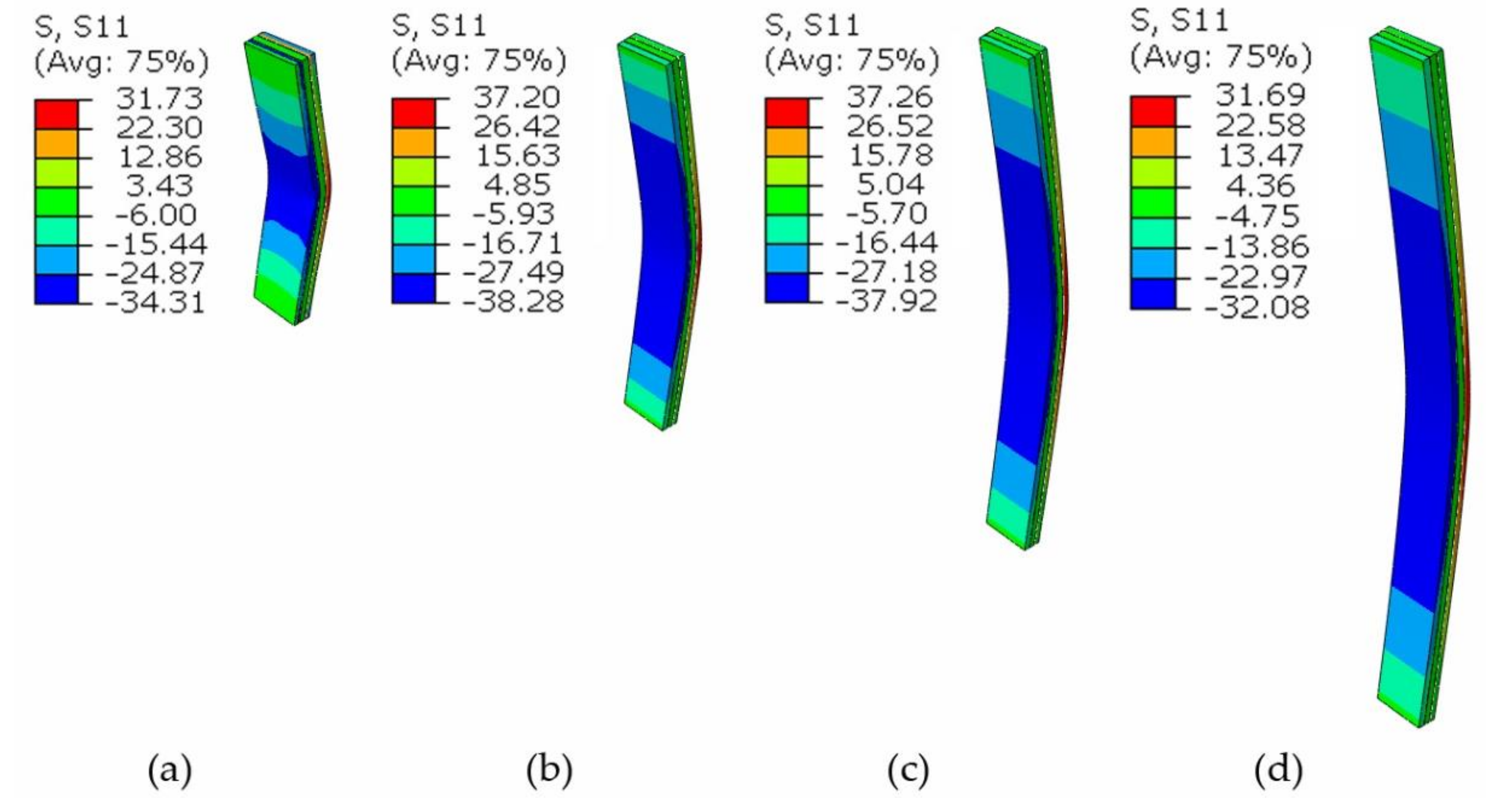
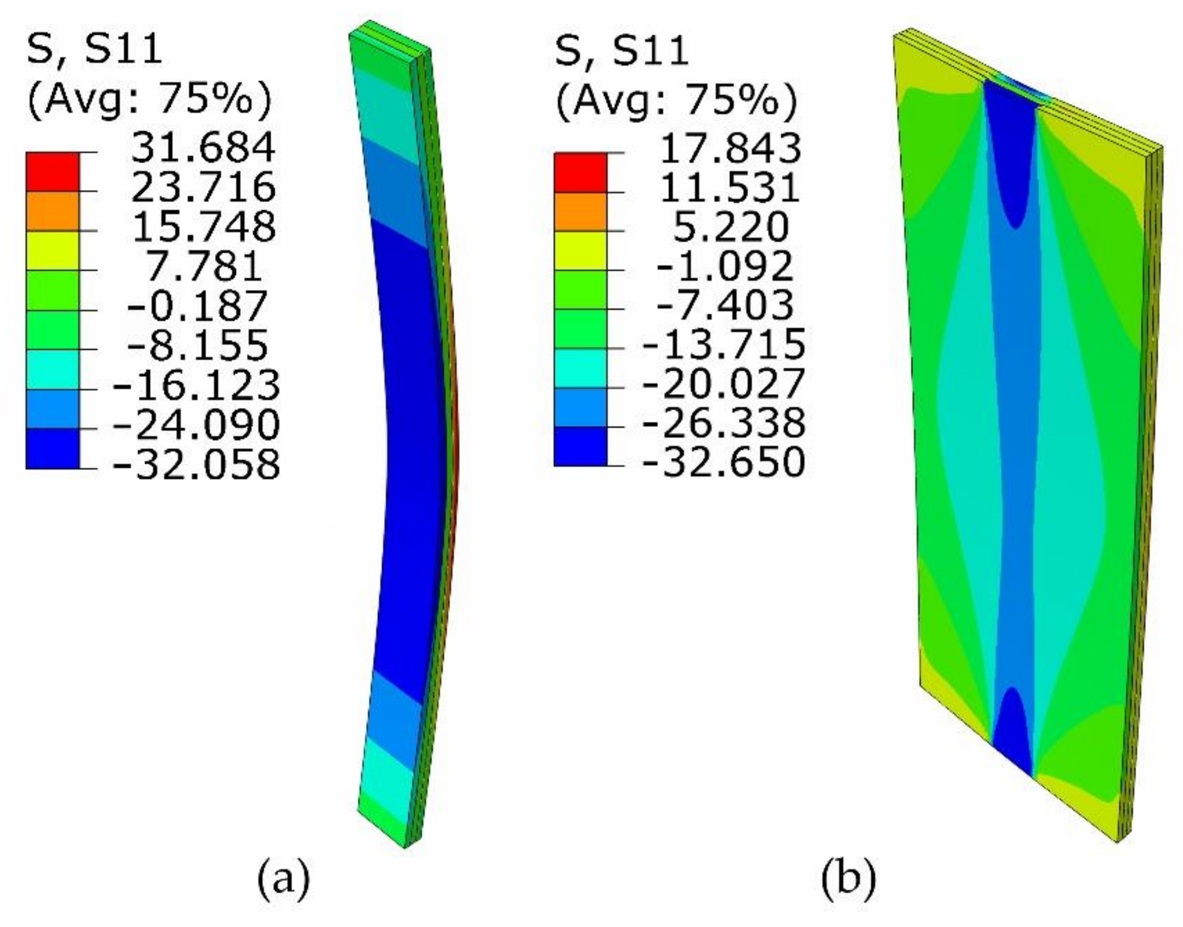
3.2. The Effect of Bearing Length

The buckling behavior of fully loaded and partially loaded CLT members with different aspect ratios and bearing lengths were simulated with the validated FE model.
The stress distribution of a fully loaded and a partially loaded CLT member is shown in Figure 7. The stress was evenly distributed along the width of the fully loaded member; however, the stress varied in the width of partially loaded member. Then, the stress along the width of a partially loaded CLT member for the half of the height was extracted from the result database and is shown in Figure 8. It was found that the stress decreased with the increase in distance to the loading area. Thus, the part of CLT beyond the loading area could serve as constraints to the part of CLT within the loading area, because the part of CLT beyond the loading area buckled later or even did not buckle under the applied load. Due to this, the available calculation method for buckling capacity of fully loaded CLT members is not suitable for partially loaded CLT members.
The buckling capacity of CLT members with different configurations was obtained from the FE model. For each slenderness ratio, the buckling capacity of the fully loaded CLT member was taken as a reference, Fre, and the buckling capacity of partially loaded members F was normalized as F/Fre. The bearing length ratio was expressed as ρ = b/bre. The relationship between the normalized buckling capacity F/FRE and the bearing length ratio b/bre are shown in Figure 9. In the figure, the bearing capacity of CLT members due to material failure FMF was also calculated and normalized as MF = FMF/Fre. Note that FMF/Fre is the reciprocal of the coefficients of stability φ, which is defined as Fre/FMF.
It is evident from this figure that with increasing bearing length ratio, the buckling capacity increased for all CLT members with different slenderness ratios. Additionally, the buckling capacity finally tended to the bearing capacity due to material failure. This indicated that the unloaded part of CLT served as lateral constraints to the loaded part of CLT, and the longer the unloaded part, the stronger the constraint was; at some length, the constraint was so strong that the loaded part of CLT member would fail due to material failure instead of buckling.
The relationship between the normalized buckling capacity of CLT members with the slenderness ratio is shown in Figure 10. It can be seen from the figure that for the same bearing length ratio, the normalized buckling capacity increased with the increase in slenderness ratio. This indicated that the larger the slenderness ratio, the more obvious the constraint of the unloaded part to the loaded part of CLT members.

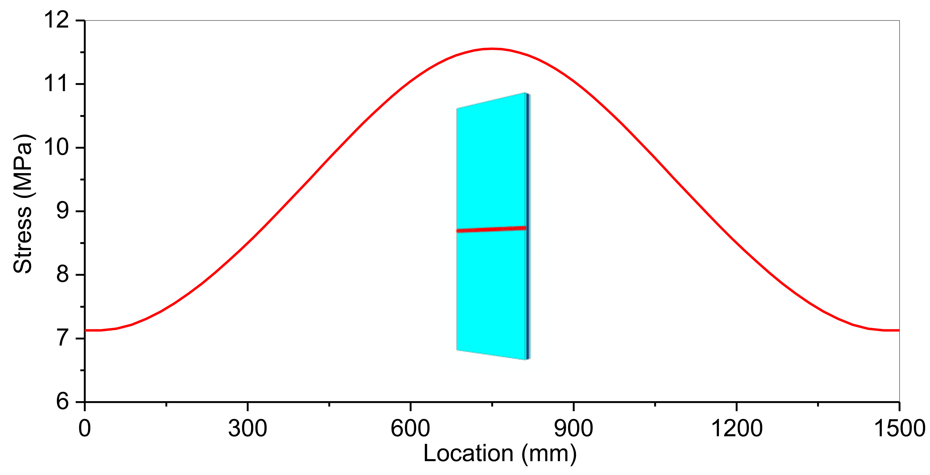
3.3. The Calculation Method for the Partially Loaded CLT Members

To address the effect of bearing length on the buckling capacity of axially and partially loaded CLT members, an equivalent width method (EWM) was proposed based on the numerical findings. To calculate the buckling capacity, it is suggested that a partially loaded CLT member be replaced by a fully loaded CLT member with an equivalent width of beq.
Given that the width of the CLT member is b, and the load is applied to the member along a length of bre, the relationship between the equivalent width and the load-bearing length can be expressed as beq = βbre. The coefficient β depends on both the slenderness ratio γ and the load bearing length ratio ρ = b/bre. Based on the parametric study, the coefficient β is between 1 and α and can be determined as,
β = ρ when :     1 ρ 1 10 α 2 1 2 α + 1 l i n e a r   i n t e r p o l a t i o n when :     1 10 α 2 1 2 α < ρ < 2 3 2 α 1 + 1 1 10 ρ 2 α + α when :     2 3 2 α 1 + 1 ρ 2 α α when :     ρ > 2 α
where ρ is b/bre, and α is FMF/Fre, which is also the reciprocal of the coefficients of stability φ. Note that the coefficient of stability is a function of slenderness ratio γ and the corresponding calculation method has been provided in design codes like CSA O86, etc. Additionally, Formula (1) is shown in Figure 11.
A comparison of the predicted the calculated buckling capacity via the EWM is shown in Figure 12. It can be seen that the calculated results agreed well with the numerical results at larger and smaller bearing length ratios, and the EWM provided conservative results at medium bearing length ratios.
Thus the developed EWM is deemed reliable to calculate the buckling capacity of partially loaded CLT members.

4. Conclusions

The FE model was developed to investigate the buckling behavior of partially loaded CLT members. After being validated, the FE model was used to investigate the buckling capacity of partially loaded members with different slenderness ratios and load-bearing length ratios. Based on the numerical findings, an equivalent width method (EWM) was proposed to calculate the buckling capacity of partially loaded CLT members, and the corresponding formula to calculate the equivalent coefficient was proposed.
It was found that the unloaded part of CLT served as constraints to the loaded part of CLT members. The longer the unloaded part, the stronger the constraint was.
The buckling capacity increased with the increase in bearing length ratio for CLT members with the same slenderness ratio, and buckling capacity increased with the slenderness ratios for CLT members with the same bearing length ratio.
The buckling capacity of partially loaded CLT member can be calculated by replacing it with a fully loaded CLT member with an equivalent width. The proposed EWM was proved reliable and easy to apply.

Author Contributions

Conceptualization, G.W.; methodology, G.W.; formal analysis, Y.S. and L.H.; investigation, Y.S.; resources, G.W. and Y.S.; data curation, L.H.; writing—original draft preparation, Y.S.; writing—review and editing, G.W. and H.R.; visualization, L.H.; supervision, H.R.; project administration, H.R.; funding acquisition, G.W. and Y.S. All authors have read and agreed to the published version of the manuscript.

Funding

This work was funded by the National Natural Science Foundation of China (Grant No. 51808546 and 52008011).

Institutional Review Board Statement

Not applicable.

Informed Consent Statement

Not applicable.

Data Availability Statement

The data used to support the findings of this study are available from the authors upon request.

Conflicts of Interest

The authors declare no conflict of interest.

References

  1. Gagnon, S.; Pirvu, C. CLT Handbook: Cross-Laminated Timber (Canadian ed.); FPInnovations: Quebec, QC, Canada, 2011. [Google Scholar]
  2. Brandner, R.; Flatscher, G.; Ringhofer, A.; Schickhofer, G.; Thiel, A. Cross laminated timber (CLT): Overview and development. Eur. J. Wood Wood Prod. 2016, 74, 331–351. [Google Scholar] [CrossRef]
  3. Kaaracabeyli, E.; Douglas, B. CLT Handbook: Cross-Laminated Timber (U.S. ed.); FPInnovations and Binational Soft-wood Lumber Council: Leesburg, VA, USA, 2013. [Google Scholar]
  4. ANSI; APA. Standard for Performance-Rated Cross-Laminated Timber (PRG 320); APA-The Engineered Wood Association: Tacoma, WA, USA, 2018. [Google Scholar]
  5. British Standards Institution. Timber Structures Cross Laminated Timber Requirements (BS EN 16351); BSI Standards Limited: London, UK, 2015. [Google Scholar]
  6. National Technical Committee for Wood Standardization. Cross Laminated Timber (LY/T 3039-2018); China Quality and Standards Publishing & Media Co., Ltd.: Beijing, China, 2018. [Google Scholar]
  7. National Technical Committee for Wood Standardization. Strength Classes for Structural Timber (LY/T 2383-2014); China Quality and Standards Publishing & Media Co., Ltd.: Beijing, China, 2014. [Google Scholar]
  8. Kudo, Y.; Nakajima, S.; Miyatake, A.; Araki, Y.; Shibusawa, T.; Haramiishi, T. Evaluation of buckling strength of cross laminated timber. In Proceedings of the World Conference on Timber Engineering (WCTE2016), Vienna, Austria, 22–25 August 2016. [Google Scholar]
  9. Pina, J.C.; Flores, E.I.S.; Saavedra, K. Numerical study on the elastic buckling of cross-laminated timber walls subject to compression. Constr. Build. Mater. 2019, 199, 82–91. [Google Scholar] [CrossRef]
  10. Perret, O.; Douthe, C.; Lebée, A.; Sab, K. A shear strength criterion for the buckling analysis of CLT walls. Eng. Struct. 2020, 211, 110344. [Google Scholar] [CrossRef] [Green Version]
  11. Huo, L.L.; Wu, G.F.; Wang, H.J.; Zhu, E.C. Calculation of the stability coefficient of cross-laminated timber members in axial compression. J. Build. Struct. 2021, 42, 107–116. [Google Scholar] [CrossRef]
  12. Huang, Z.; Huang, D.; Chui, Y.-H.; Shen, Y.; Daneshvar, H.; Sheng, B.; Chen, Z. Modeling of Cross-Laminated Timber (CLT) panels loaded with combined out-of-plane bending and compression. Eng. Struct. 2022, 250, 113335. [Google Scholar] [CrossRef]
  13. Thiel, A.; Krenn, H. Buckling loads for cross-laminated timber elements under uniaxial in-plane compression. In Proceedings of the World Conference on Timber Engineering (WCTE2016), Vienna, Austria, 22–25 August 2016. [Google Scholar]
  14. Perret, O.; Lebée, A.; Douthe, C.; Sab, K. The bending-gradient theory for the linear buckling of thick plates: Application to cross laminated timber panels. Int. J. Solids Struct. 2016, 87, 139–152. [Google Scholar] [CrossRef]
  15. Perret, O.; Douthe, C.; Lebée, A.; Sab, K. Buckling of cross laminated timber walls. In Proceedings of the World Conference on Timber Engineering (WCTE2016), Vienna, Austria, 22–25 August 2016. [Google Scholar]
  16. Canadian Standards Association. Engineered Design in Wood (CSA-O86); Canadian Standards Association: Toronto, ON, Canada, 2009. [Google Scholar]
  17. American Wood Council (AWC). National Design Specification for Wood Construction; American Wood Council (AWC): Washington, DC, USA, 2015. [Google Scholar]
  18. European Committee for Standardization (CEN). Eurocode 5-Design of Timber Structures-Part 1-1: General Rules and Rules for Buildings; European Committee for Standardization: Brussels, Belgium, 2003. [Google Scholar]
  19. Thiel, A.; Brandner, R. ULS design of CLT elements-basics and some special topics, cross laminated timber—A competitive wood product for visionary and fire safe buildings. In Proceedings of the Joint Conference of COST Actions FP1402 and FP1404, Stockholm, Sweden, 10–11 March 2016. [Google Scholar]
  20. proHolz Austria. Cross Laminated Timber Structure Design; Eberl Print: Immenstadt, Germany, 2014. [Google Scholar]
  21. Swedish Wood. The CLT Handbook-CLT Structures-Facts and Planning; Föreningen Sveriges Skogsindustrier: Skellefteå, Sweden, 2019. [Google Scholar]
  22. Hill, R. A Theory of the Yielding and Plastic Flow of Anisotropic Metals. Proc. R. Soc. Lond. Ser. A Math. Phys. Sci. 1948, 193, 281–297. [Google Scholar] [CrossRef] [Green Version]
  23. Forest Products Laboratory. Wood Handbook-Wood as an Engineering Material (Centennial Edition); General Technical Report FPL–GTR–190; U.S. Department of Agriculture, Forest Service, Forest Products Laboratory: Madison, WI, USA, 2010; Volume 1.
  24. Ruan, G.; Xiong, H.; Chen, J. Bending and rolling shear properties of cross-laminated timber fabricated with Canadian Hemlock. SDHM Struct. Durab. Health Monit. 2019, 13, 227–246. [Google Scholar] [CrossRef] [Green Version]
Figure 1. CLT members with different boundary conditions: (a) CLT members with two opposite sides simply supported; (b) CLT members with all four sides simply supported.
Buildings 12 00084 g001
Figure 2. CLT member with load imposed on part of the member. (a,b) Photos of partially loaded CLT members; (c) diagram of partially loaded CLT members.
Buildings 12 00084 g002
Figure 3. FE model of CLT members.
Buildings 12 00084 g003
Figure 4. CLT model used in the parametric study.
Buildings 12 00084 g004
Figure 5. The predicted buckling capacity versus tested capacity.
Buildings 12 00084 g005
Figure 6. The deformation and stress distribution for four groups of CLT member with different height: (a) 1400 mm; (b) 2100 mm; (c) 2800 mm; (d) 3500 mm.
Buildings 12 00084 g006
Figure 7. Stress distribution of CLT members: (a) fully loaded member; (b) partially loaded member.
Buildings 12 00084 g007
Figure 8. Stress distribution along the width of a partially loaded CLT member.
Buildings 12 00084 g008
Figure 9. The normalized buckling capacity of CLT members versus bearing length ratios.
Buildings 12 00084 g009
Figure 10. The normalized buckling capacity of CLT members versus slenderness ratios.
Buildings 12 00084 g010
Figure 11. Plot of Formula (1).
Buildings 12 00084 g011
Figure 12. Comparison of the predicted and calculated buckling capacity of CLT members versus bearing length ratios.
Buildings 12 00084 g012
Table 1. Material properties of hemlock (average).
Modulus of Elasticity
(MPa)
Shear Modulus
(MPa)
Poisson’s RatioCompression Strength
(MPa)
Shear Strength
(MPa)
(0°)(90°)(0°)(90°)υ12υ23υ13(0°)(90°)(0°)(90°)
EE/30E/1653.10.120.30.1237.34.57.31.28
Table 2. Information of CLT buckling test.
Dimension/mmReplicatesAverage Buckling Capacity/kNAverage Modulus of Elasticity/MPaAverage Compression Strength/MPa
1400 × 280 × 1054549.612,73732.2
2100 × 280 × 1054385.6997832.2
2800 × 280 × 1054290.510,63634.7
3500 × 280 × 1054168.9927331.8
Publisher’s Note: MDPI stays neutral with regard to jurisdictional claims in published maps and institutional affiliations.

