1. Introduction
Solar protection devices play a relevant role in the energy performance of buildings and the shading potential of a given technology depends on its optical properties and performance, as analyzed and discussed in [
1,
2]. This topic is particularly relevant in modern architecture, characterized by the massive use of transparent materials.
Solar shading also affects daylight and, consequently, the quality of vision through and the energy use for electric lighting [
3]; therefore, alternative approaches aimed at balancing thermal and daylighting performance are proposed [
4], and the higher the complexity of the system, the higher the cost [
5]. In the case of standard and manually operated shading systems, their operations mainly involve glare control with a positioning based on user experience and decided in accordance with the average expected sun conditions for the day. Thereafter, users will not be prone to changing the predefined setup, but will rather, and if necessary, prefer to switch on the lighting indoors [
6]. In this perspective, static shading systems can also play a relevant role in energy savings if specifically designed and parameterized according to the characteristics of the climatic site where they will be installed and to respect the management of solar gains such as visual comfort.
Three-dimensional (3D) systems are gaining interest as a solution for second skins in buildings because the 3D discretized geometry allows easy paneling and shading of contemporary architecture glazed façades, often characterized by complex single and double-curved surfaces. For this purpose, new materials from other industry sectors, enhanced traditional materials, and advanced surface treatments are used to form fixed screens parallel to the façade (panels), overhangs, fixed or adjustable slats and complex-shaped second skins.
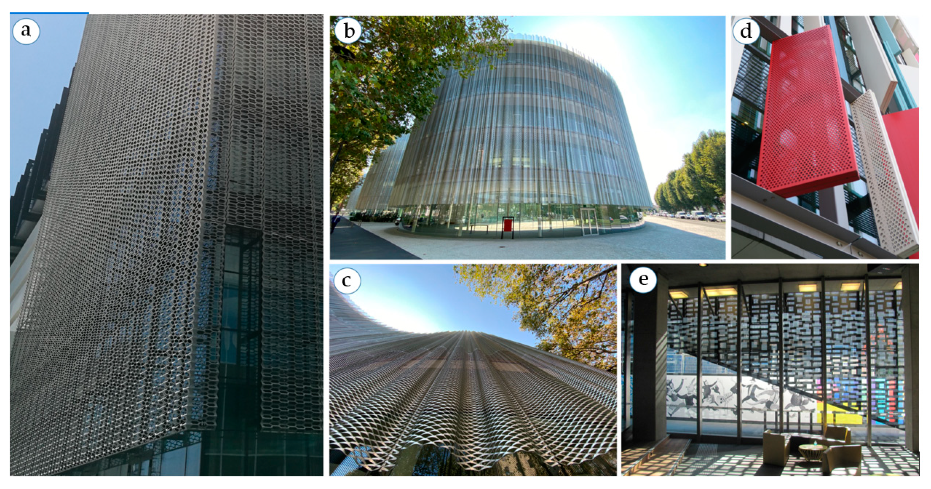
Figure 1 presents exemplary cases of transparent façades covered by static 3D shading systems: the way they affect the outdoor and indoor visual aspects of the built environment is easily inferred, while the impact of such technology on the building energy and visual performance is little explored. Although fixed shading devices are cost-effective and easy to implement, their performance has limitations in coping with variable weather conditions throughout the year. Furthermore, the simulation results suggest that the properties and the type of the shading system should vary with orientation [
7]. A detailed analysis should always be realized during the early design stages, to maximize the impact of a critical decision on the overall performance of the building envelope and the building itself.
In fact, static façade devices affect solar heat gains and daylight availability throughout the year, reducing most of the cooling loads during summer, but increasing the heating demand in winter [
8]. Different calculation and assessment approaches for optimization were proposed and mostly considering non-residential building applications.
Simplified models and geometries of perforated screens were used to assess their thermal and optical performance [
9]. The purpose of a similar analysis is to correlate the dimension of the openings with the thickness of the screen correlating the thermal and visual performance metrics with the geometry under a statistical Analysis of Means (ANOM) framework [
10]. Analogous results were obtained in [
11], where an assessment of the minimum perforation of solar screens was investigated for hot and arid climate conditions. In both cases, a perforation rate between 30 and 50% was considered as a compromise to control solar gains and to retain, at the same time, adequate indoor illuminance.
In recent years, few authors have focused on expanded metal meshes and considered effective alternatives in both improving the view while reducing radiant energy gain by reflecting or filtering sunlight. Their appearance is almost nearly transparent considering pre-defined outdoor view directions [
12]. Other authors have focused on perforated screens, metal mesh and grids, evaluating them as shading alternatives for cooling dominated office spaces [
13]. Using simplified models of these screens, different openness factor values were analyzed with the purpose of evaluating the optimal compromise among cooling demand reduction and heating and lighting demand increase. The author reached the conclusion that the openness factor is not an adequate parameter to define their performance as solar shading systems.
The dialogue with some professionals revealed that in cases in which non-conventional solar shading surfaces are proposed by the designer, the assessment of the early design energy performance of the envelope will likely use the openness factor measured at normal incidence as a proxy of solar transmittance, thus neglecting the angular component.
This approach has already been questioned for conventional shading systems since the use of a constant transmittance value can lead to significant errors in the calculation of optical and energy performance. In several samples of less complex materials such as textiles for shading, the measured transmittance could be 2–3-fold greater than the value of the openness factor expressed as a percentage [
14].
An additional problem arises with the calculation standards, the applicability of which is limited to simple shading system geometries [
15,
16].
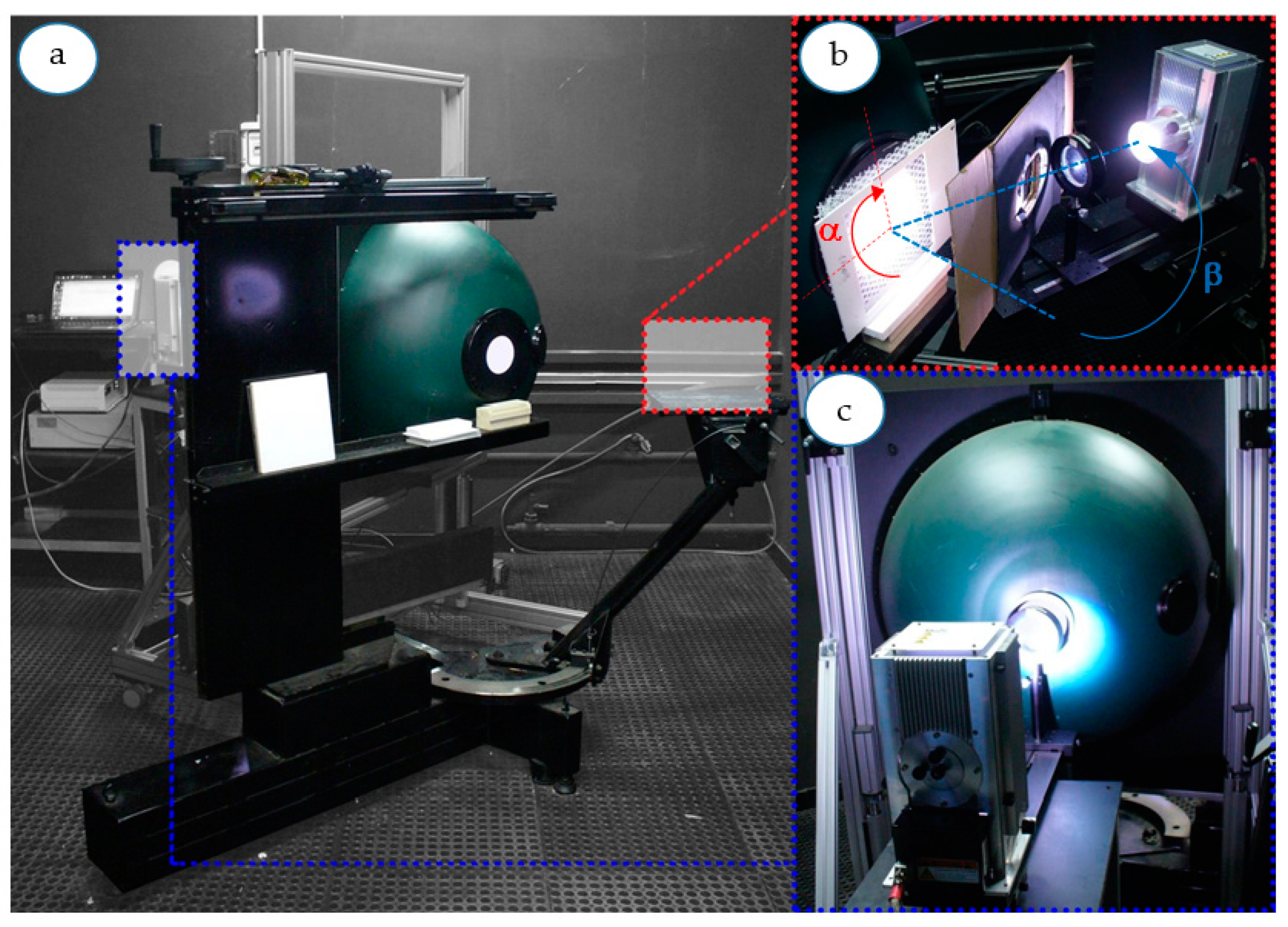
Few suitable measurement procedures for large texture and complex geometry systems exist and are used to determine the hemispheric angular transmittance of dedicated samples [
17]. These procedures involve a light source with a diameter that must be large enough to fully sample the texture and any asymmetries arising from the geometry so that normal and angular measurements are independent of sample positioning
Procedures for the measurement of the off-normal solar and visual properties of standard shading systems, such as roller blinds [
18], fabrics and insect screens [
19] and involving the use of spectrometers, exist in the literature. The measurements include the evaluation of both beam and diffuse components for transmittance and reflectance. The variation of the transmittance with the light beam incidence angle was then approximated as a cosine power function of the measured angular solar profiles. These profiles could be then used as a proxy of the shading performance of the several systems tested. The effectiveness of the measurements, in this case, is limited to small planar samples, with a regular and simple texture.
Bidirectional scattering distribution functions (BSDFs) were utilized in recent years to adequately include directional, e.g., scattering, properties of woven shade materials in simulation programs [
20]. In this case, the optical performance is measured using a goniophotometer and for samples with a very small size.
It is possible to replace, but not entirely, measurement with virtual goniophotometers and simulations. However, this type of approach is suitable for samples with uni-directional geometries (e.g., lamellae), or for samples in which the effort required for 3D modelling is often marginal or not very demanding. By using virtual copies of both the samples and the measuring apparatus, the authors of [
21,
22] were able to obtain results with a good level of accuracy, adequately reproducing the optical performance of an innovative slat type.
Despite the high-quality optical performance evaluations obtained, these latest procedures are time-consuming and costly, thus poorly suited to rapid broad-spectrum screening.
The performance assessment of these systems generally relays on simulation, based on geometric and physical models, which are computationally demanding and with several limitations [
23]. Major difficulties concern the correct processing of complex geometries, especially in the case of single and double-curved surfaces, as well as the correct assignment of the reflectance properties of the raw material used for the screen.
These 3D systems have complex geometries, varying in thickness, openness, and texture and the accurate determination of their optical and solar properties is a crucial step. Key parameters to take into account are system curvature, internal ray reflection, and edge effect. The objective of this paper is the optical characterization of 3D systems concerning their solar protection potential for façade applications. Despite several solutions already available on the market, such data are seldom available, since commercial instruments, as spectrophotometers, are not suitable to provide accurate measurements. The implementation of a reliable dataset and a preliminary analysis at the material level is necessary to lay the conditions for the successive assessment of the technology by architectural design, as well as energy and lighting performance analyses at the building level.
2. Materials and Methods
2.1. Methodological Background and Limitations
This study is articulated in the following subsequent phases:
Identification, selection and description of samples of significant 3D materials for building applications, including their relevant geometric and material characteristics;
Experimental determination of the sample’s relevant optical properties, as a function of the wavelength and the incident solar radiation angle;
Evaluation of the angular transmittance properties of the selected samples, including comparison against a reference standard fixed shading system.
This is a preliminary study limited to analyzing the potential of 3D skins to provide an effective solar protection to façades. Other aspects of the technology are, however, critical: the impact on daylighting, visual quality issues related to diffraction phenomena and excessive obstruction of the external environment, ageing and soiling problems, especially for metallic skins. These aspects are out of scope in the present study, but they will be the object of future studies, which will benefit from the findings presented here.
2.2. Identification of Product Categories
A screening campaign aimed to search for alternative materials for shading systems was carried out to identify materials with standard or large three-dimensional texture geometry structure, suitable to be applied as an external building skin, with solar shading potential [
24]. Promising solutions are not necessarily from the building industry but are also related to the product design, automotive, agriculture technology, fashion design and mechanic sectors. They can be categorized as follows:
The metal mesh and metal grid consist of metallic filaments that are weaved to create a rigid panel. These materials are used in the building sector for façades, fences and shading systems. The grid solutions typically have the same element and spacing as warp and weft, while the mesh systems usually have different filament sections and different spacing. Filaments can have different geometry (circular, elliptical, and rectangular), sizes (1–10 mm) and are manufactured using different raw materials (steel, stainless steel, copper, and brass). These parameters affect the flexibility and bendability of the system as well as its transparency. The use of wires with a small diameter made from flexible materials makes these systems like textiles that can have the same optical properties of a standard textile but with higher mechanical properties (micro wired metallic grids).
Metallic plissé grids are an evolution of the micro metallic grids that, if subjected to a further bending process, recreate their typical folded section. The result is a flexible, mono-directional bending element that requires an additional external frame as a support system. These materials have high durability and are typically used as air, oil and liquid filters for different applications.
The 3D expanded metal meshes are typically produced by cutting and cold pressing the metal foil (sheets or roll) [
25]. It is possible to customize the hole shape and dimension but also the mechanical properties and its finishing. Hole geometry and sheet finishing, together with the production process, affect the final geometry (with no symmetry). They are generally heavier compared to the alternatives previously described. The double curvature of a single panel is not allowed and single curvature is limited to custom non-ordinary projects such as the Bocconi University new campus in Milano (
Figure 1b,c).
The cheap and easily malleable plastic grid materials came from the building sector and are used as water draining layers, protection layers or groundwater filters. These materials are lightweight, flexible and resistant even if designed for non-sun-exposed use (the mechanical properties of the polymer used decrease if exposed to UV light). The selected samples included additives to preserve the material from UV radiation.
The 3D textile materials are typically used for fashion, matrasses cover, car interiors, backpacks and shoes. They are produced either as a woven filament that recreates different hole geometries or reproduces complex geometries by joining two or more textile layers with polymeric filament (PET, PES, and PP) to change surface finishing and total thickness. These textiles are resistant to rips and abrasions and their structure allows them to recover their original shape after compression.
2.3. Selected Samples
Fourteen samples are selected as representative of each category and the main characteristics are summarized in
Table 1.
The metal mesh (MM) samples consist of an uncoated stainless steel warp and weft. The weft is a rigid element with a 1.5 mm diameter circular section, locally deformed around warp filament. The gross spacing between weft elements is 3 mm (MM_1), 5 mm (MM_2) and 8 mm (MM_3). Warp elements are flexible wire ropes with a 2 mm continuous circular section and a 17.5 mm gross spacing. Warp and weft create a 4 mm thick system with a 44%, 62% and 72% openness factor, respectively. The metal grid (MG) sample has both warp and weft with a 0.7 mm circular section and a 1.67 mm gross spacing (filament diameter-spacing ratio 1:1). The system is 1.5 mm thick and has a 34% openness factor.
The perforated metal sheet samples are aluminum (PS_1) and zinc-plated steel (PS_2) perforated sheets. The forming process produces holes, with a shape that depends on the geometry of the rotary pinned perforation roller. The two samples have, respectively, 20 × 5 mm ogival holes and 2 mm diameter circular holes. The expanded metal mesh (EX) sample is an aluminum deformed sheet. The process recreates oblong hexagonal holes. The plissé metal grid (PL) sample is a micro metal grid structure with the same circular filament as warp and weft (equal to the spacing between filaments). The folding process gives the sample a total thickness of 1.1 cm.
The HDPE mesh (HD) selected samples are obtained by plastic fused filament deposition. The productive process generates a non-repeatable structure generated by the union of three layers. The HD_1 first and second layers consist of a thin filament with a 45° rotation (the first layer is 45° clockwise, while the second layer is rotated 45° counterclockwise) and constant spacing. The HD_2 central layer is made of a bolder filament with a vertical arrangement. The generated systems have a total thickness of 0.4 and 0.7 cm, respectively.
The 3D textile (TX) selected sample is a polyester woven structure. In the 1 cm thick sample, the upper and lower layers are offset from each other by half the diameter of the hexagonal holes that characterize the texture of both layers. The two external layers are connected through an interlocking net of yarns.
4. Results
The solar reflectance and transmittance values are calculated starting from spectral data and the full set of results is presented in
Table 2. Values in the visible range are almost identical to the former, depending almost uniquely on the 3D geometry; the results will be then presented for the solar quantities for brevity, but they apply for the visible quantities as well. The near-normal solar reflectance and the angular solar transmittance values are reported in
Table 2, for α = 0°, left, and α = 90°, right.
Eleven products exhibit normal solar transmittance in the 40–53% range, the value drops to 20% for PL, while the two largely spaced metal meshes (MM_2, MM_3) have a solar transmittance of 66% and 73%, respectively. The sample shows different responses as a function of the incidence angle and sample orientation, the latter does not apply for samples with rotation symmetry.
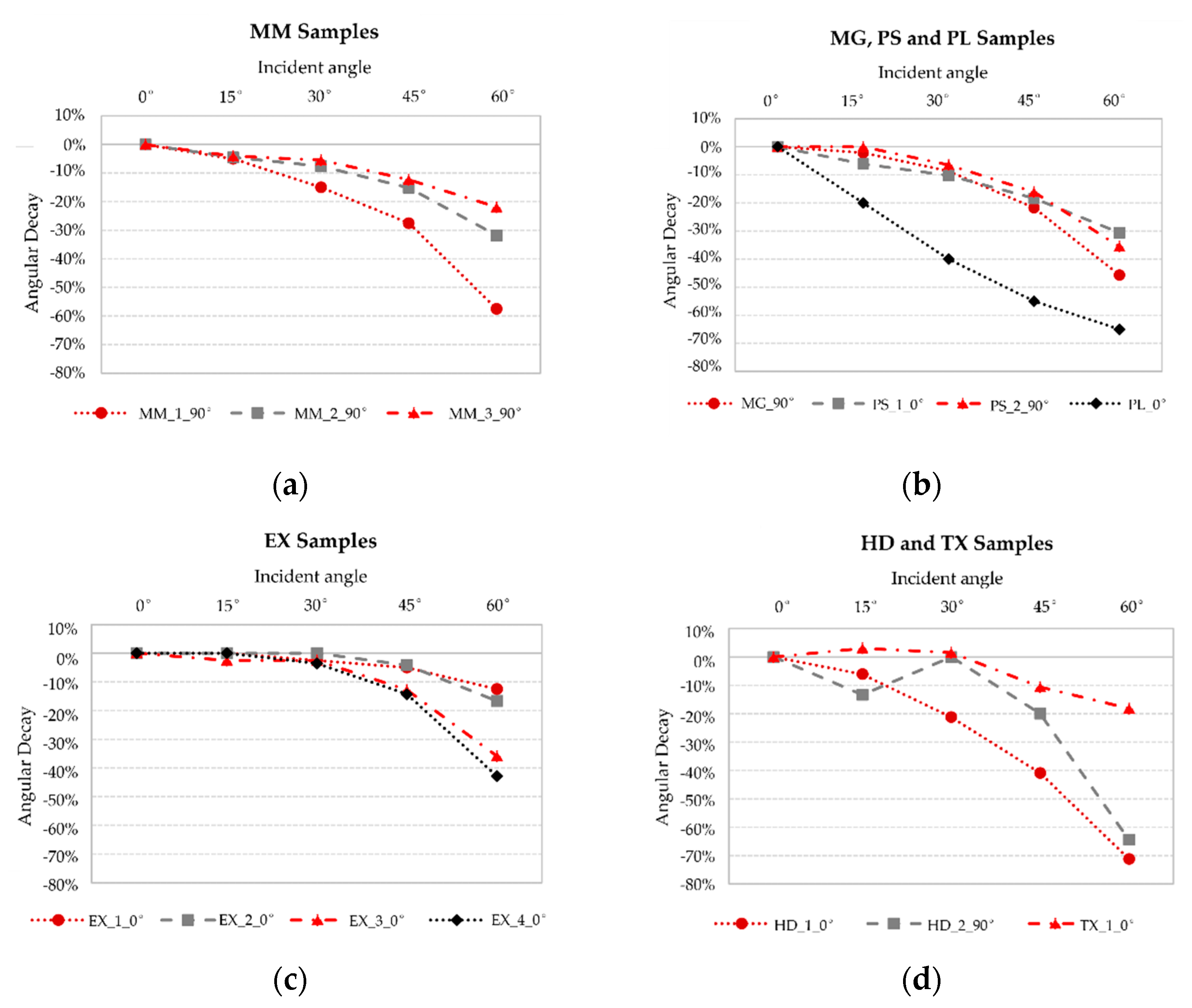
Figure 3 presents the relative transmittance angular decay of the tested products; the results refer to the rotation angle that provides the highest shading potential.
Due to their texture, the angular decay of MM series solar transmittance is similar to that of un-shaded glazing units for the α = 0°. The shading effect is relevant at α = 90°: MM_1 angular transmittance decreases by 25% and 58% at 45° and 60°, respectively. The larger spacing of MM_3 limits the shading potential; in fact, the transmittance decay is 12% and 22% at 45° and 60°, respectively. Sample MM_2 exhibits intermediate performance with a transmittance reduction of 32% at 60°. MG transmittance drop by 17% at 45° and 46% at 60°, resulting effective at a high incidence angle.
The symmetrical arrangement of the circular holes gives a 35% peak reduction at a 60° incidence angle for PS_2. In contrast, PS_1 exhibits different shading potential depending on its lying position: it is negligible at α = 90° but the transmittance reduction is 18% and 31% at 45° and 60° incidence angles for the most effective rotation angle. PL shading potential increase with the incidence angle for α = 0°, τe decreases by 40% at 30° and 65% at 60°; more complex is the angular dependence at α = 90°, and τe increases by 35–75% in the 15–45° range and decreases by 30% at 60°.
Sample EX_1 and 2 do not present significant variations with the incidence angle for α = 0°, peaking at 17% reduction at 60° for the EX_2 case; in addition, they exhibit an increase in the 30 and 45° transmittance compared to the normal incidence value for α = 90°. EX_3 and 4 exhibit significant angular selectivity at 45° and 60°, with a transmittance reduction of 43% and 32%.
The HD and TX textures determine a mixed and complex optical behavior. TX does not exhibit significant angular selectivity, with a peak of a 18% reduction at a 60° incidence angle for α = 0°. HD_1 and 2 are the samples with the higher off-normal shading effect, with a transmittance reduction of 71% and 64% at a 60° incidence angle, and a reduction in the 20–40% range is achieved at a 45° incidence angle.
The near-normal solar reflectance values are reported in the first column of
Table 2. The values do not change for measurements on both sides (front and back), nor for the visible range. HD samples exhibit very low reflectance values (1–2%) because of the high openness factor coupled with the black color. The results for metal meshes depict the impact of the openness factor on solar reflectance well—it doubles (10 to 21%) for MM_1 compared to MM_3. The solar reflectance values range from the very low values (1–2%) of the largely spaced plastic grid and 39–44% of the perforated metal sheets. Excluding PS_1 (ρ
e 44%), the reflectance is in the 17–33% range.
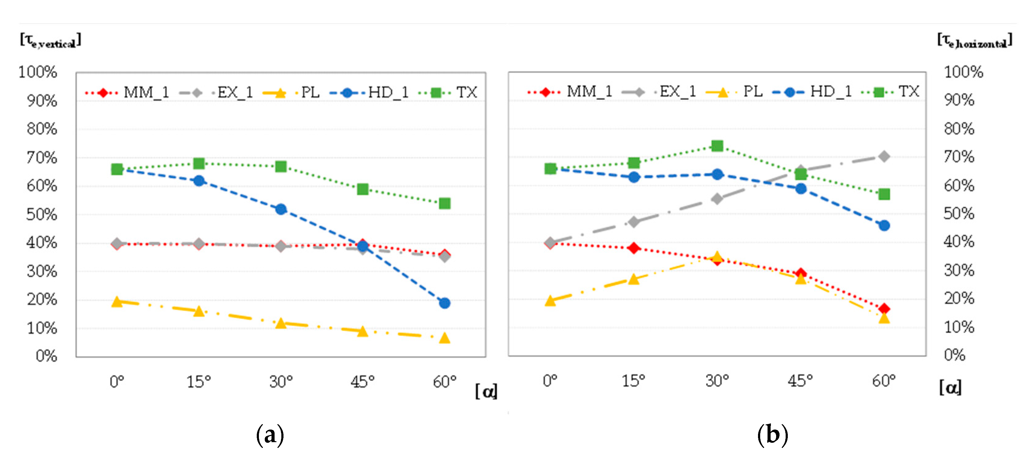
An extract of the performance of some of the most representative materials is then reported in
Figure 4. The materials reported were selected to identify the variability of the results arising from the different product families tested, but also as a comparison against the results previously reported for fixed louvre systems.
5. Discussion
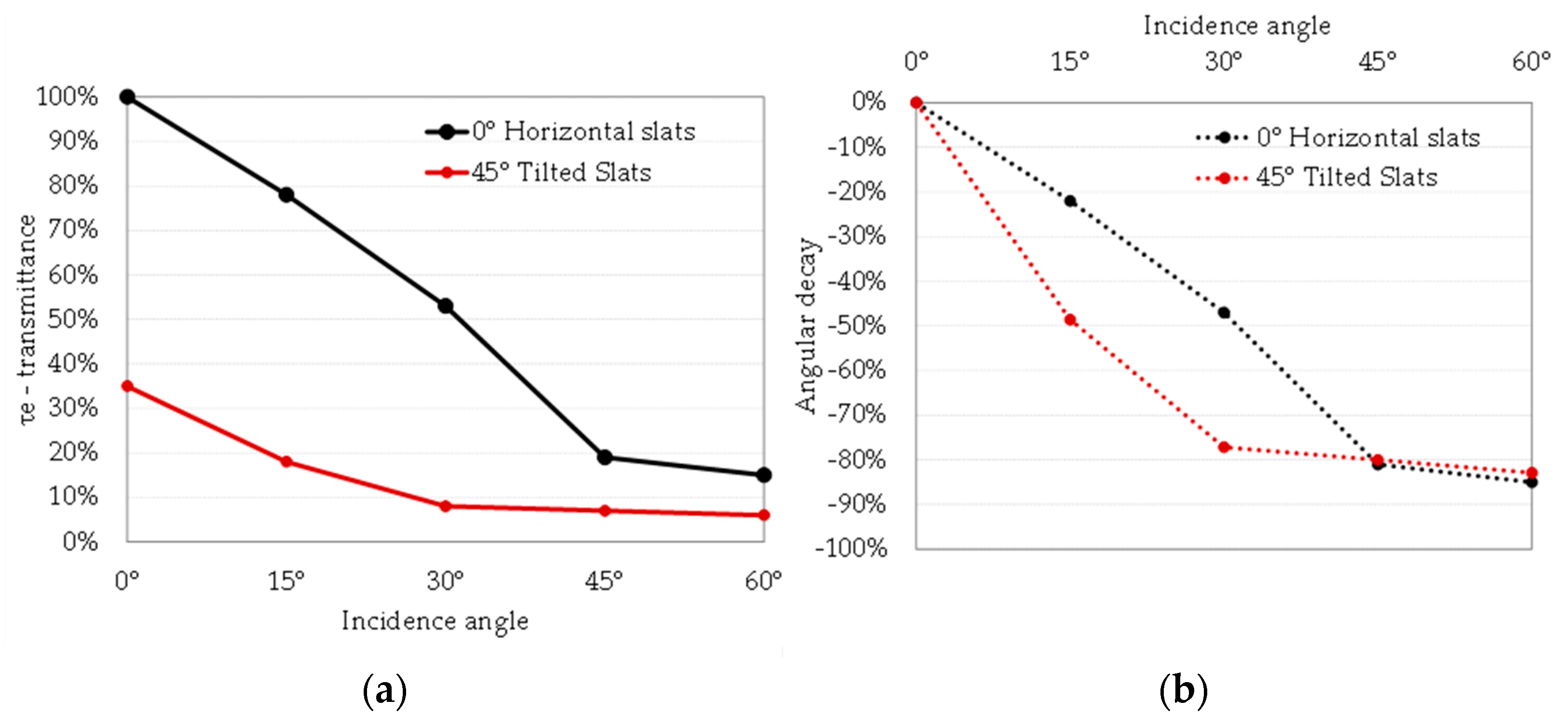
The results provide a comprehensive dataset of 3D skins and depict a composite landscape of products with different solar shading potentials. Being static solutions, the performance-driving parameters are the openness factor, which determines solar transmittance at a normal incidence angle, and the off-normal angular selectivity, since the highest solar gains are harvested in summer with the sun high on the sky vault. Such parameters can be compared to a conventional shading system, consisting of static horizontal slats with the same reflectance of the selected metal elements. It is known that these shading devices, if properly designed, provide good daylighting and prevent overheating. Assuming that the slats exhibit Lambertian behavior and have a depth equal to pitch, the calculated normal solar transmittance is 100% and 35% for slats that are horizontal and tilted 45°, respectively The angular decay is calculated in accordance with EN ISO 52022-3 [
27]. At an off-normal incidence angle, horizontal louvre system transmittance is halved at 30° and it is cut by 80% at 45°; the tilted slat louvre transmittance is reduced by 77% at 30°, increasing at higher angles, as reported in
Figure 5. For comparison purposes, it must be noted that conventional glazing unit transmittance decreases typically by 5 and 10% at 45° and 60° incidence angles, respectively.
At an off-normal incidence angle, 3D material performance strongly depends on the three-dimensional texture and the sample orientation angle (
Table 2 and
Figure 3 and
Figure 4). A not correct orientation can lead to higher transmittance compared to the normal incidence angle, especially for expanded metal meshes and plissé metal grids if correctly oriented against the sun path, all the materials (but EX) improve the angular selectivity at 60° with respect to the conventional glazing units. The selected samples, however, provide a limited shading potential when compared to the conventional static louvres: MM_1, PL_0, HD_1 and HD_2 exhibit solar transmittance decay by 60% or above at a 60° incidence angle. HD_2 has a peak increase in transmittance due to the geometry of the analyzed sample, whereby the grid holes are aligned so that the transmittance increases locally. At 45°, only HD_1 and PL_0° reach at least 40% of transmittance decay, which is the value scored by the conventional shading with the horizontal slats.
Some interesting findings can be derived from the experimental campaign regarding the various product families. The perforated metal sheets (PS_1 and PS_2) do not exhibit significant 3D properties until the size of the apertures and the sheet thickness become very close. This implies that acceptable shading performance can be achieved only with small holes (severe visual quality hazard) or thick sheets (high cost and structural issues).
Effective shading performance at normal incidence with metal meshes and grids is hard to achieve since this would require too low an openness factor; on the other hand, adequately spaced wires can provide significant angular selectivity. This behavior calls for an accurate design of the system to optimize the shading performance as a function of the boundary conditions, especially the view [
28].
The same consideration applies to the expanded metal sheets (EX family). The 3D structure does not ensure effective angular selectivity, and the solar protection is thus delegated to a low openness factor (low solar transmission at all angles), which can be unsustainable once the aspects related to vision and lighting are accounted. The metal strands and the long and short pitch of the diamond shape holes define a preferred light transmittance direction. For the selected rotation of the sample, this alignment starts to occur for incidence angles higher than 30°. The production process involves the realization of cuts and cold deformation, and the 3D structure can be optimized for solar protection during this phase by proper design, which did not apply to the tested products.
The plissé metal grid exhibits low normal transmittance, which makes it a product of potential interest for use as a shading element. In addition, solar transmittance increases for incidence angles up to 30°, an then decreases for incidence angles up to 60°. This behavior allows solar gains in the winter (low sun on the horizon) and effective shading during the summer months (i.e., in a temperate climate). The PES textile sample has high transmittance and low angular dependence, so it is not effective as a solar protection device, while the diffusing optical behavior makes it suitable for glare protection and daylighting surfaces do not provide adequate solar protection, but they exhibit diffusing behavior, which makes them suitable for daylighting applications. Their effectiveness is maximized when applied parallel to the façade plane for high incidence solar angles. The increase in transmittance occurs when there is an alignment of the hexagonal holes of the external layers, which are misaligned at normal incidence. The transparent polyester yarn for the three-dimensional warp gives the material a predominantly light-diffusing behavior.
HDPE materials exploit their tridimensional profile to achieve high angular selectivity (solar transmittance below 20% at a 60° incidence angle at their most effective orientation), despite a high openness factor. This indicates the good potential of the product since combining void area and 3D texturing can provide performance similar to real shading devices. Another positive element is the reduced cost, but the lifetime is in the 5–10 years range.
The analysis outcome is that some of these systems (MMs, HDPEs, PL and, potentially, EXs) can effectively provide solar shading to glazed façades. Their performance can be optimized by changing the geometry, thickness, openness and orientation of these complex surfaces with a computational approach, suiting thermal, lighting or energy requirements [
29]. Multi-objective algorithms can be implemented once the geometry has been built on a set of rules to create an optimized façade component [
30,
31]. Given the high number of variables these systems depend on, this study also highlights the need to develop numerical models able to accurately predict the optical behavior of 3D systems, as already achieved for conventional materials [
14,
19].
6. Conclusions
Innovative 3D materials are screened, classified and measured to understand their solar control potential and consequent application as a second building skin instead of conventional shading devices. These products vary in: used material (metal or plastic of different nature), system geometry, color and texture.
Measurements show that the openness factor is the driving parameter for optical solar properties at normal incidence and that such materials do not exhibit spectral selectivity (thus optical properties have the same value in the visible and solar range). The plissé metal grid has 20% solar transmittance; metal meshes have an average 70% solar transmittance; solar transmittance is in the 40–53% range for the remaining samples. The solar reflectance values range from the very low values (1–2%) of the largely spaced plastic grid and to a range of 39–44% for the perforated metal sheets.
The angular transmittance also depends on the color, the optical behavior of the material and the three-dimensional texture of the material, due to mutual self-shading effects and inter-reflections. It is demonstrated that such systems underperform as static conventional shading systems; however, one of the metal meshes, the plissè grid and the plastic grid exhibit relevant angular selectivity, with transmittance decay at 60° in the 58–72% range compared to the normal incidence value. All the samples underperform as conventional shading systems made of horizontal slats and most of them exhibit moderate to low angular selectivity. Few samples, namely the metal mesh grid (MM_1), HDPE meshes (HD_1 and 2) and the plissé metal grid (PL) exhibit a transmittance decay in the 58–72% range at 60°, close to that of the conventional system.
According to the results, some of the tested samples exhibit interesting potential for solar protection; however, their complexity, their flexibility in the manufacturing process, as well as the number of variables determining the shading performance suggest the need for an early-stage design of the 3D structures in a performance-based approach to optimize energy performance and architectural integration.
Ultimately, the relevance of this study is to fill the gap on reliable optical solar properties of advanced 3D skins to be used for solar protection; the presented dataset can be used for:
- (i)
Early-stage solar protection and energy performance analyses;
- (ii)
Input data to take in these products in façade and building energy performance tools;
- (iii)
Benchmark data to validate numerical models of the products analyzed.


