Article

Effect of High Magnetic Field in Combination with High-Temperature Tempering on Microstructures and Mechanical Properties of GCr15 Bearing Steel

State Key Laboratory of Advanced Special Steel, School of Materials Science and Engineering, Shanghai University, Shanghai 200444, China
*
Author to whom correspondence should be addressed.
Metals 2022, 12(8), 1293; https://doi.org/10.3390/met12081293
Submission received: 5 July 2022 / Revised: 24 July 2022 / Accepted: 29 July 2022 / Published: 31 July 2022
(This article belongs to the Special Issue Electromagnetic Preparation of Metallic Materials)

Abstract

:
The microstructures and mechanical properties of GCr15 bearing steel after high-temperature tempering with and without a 5 T high magnetic field (HMF) were investigated. It was found that the application of the HMF at the stage of high-temperature tempering slowed down the growth of the tempered sorbite (TS) structures, increased the density of the carbides, and reduced the carbide size and the volume fraction. XRD diffraction patterns showed that the HMF resulted in a higher dislocation density. Hardness testing indicated that the HMF led to an increase in the Vickers hardness in the tempered sample. It is inferred that the change in carbide size stems from the reduction in nucleation barrier in the HMF and the increase in dislocation density originates from the interaction between dislocations and carbides. Additionally, the decrease in diffusivity in the HMF also contributes to the reduction in the size of TS structures and the refinement of carbides. This work demonstrates that high-temperature tempering with an HMF can slow down the growth of TS microstructures in GCr15 bearing steel, control the carbide size, and improve Vickers hardness, which provides a new heat treatment method to regulate the microstructure and properties of GCr15 bearing steel.

1. Introduction

High carbon chromium bearing steel GCr15 has many excellent properties such as wear resistance, corrosion resistance, and anti-fatigue, and thus it is widely used for bearing rings, ball screws, bushings, and other mechanical components [1,2]. The microstructures of GCr15 bearing steel in hot-rolled conditions generally consist of lamellar pearlites and likely secondary network carbides in grain boundaries [3,4], which lead to high hardness, poor plasticity, and cold-workability. Hence, heat treatment is routinely required during the bearing manufacturing process to obtain optimum microstructures, such as uniformly distributed granular carbides in the ferrite matrix. Two types of heat treatment, i.e., spheroidization annealing and high-temperature tempering, are often used to obtain this kind of structure [5]. The tempering and quenching (Q&P) process can effectively improve the size and distribution of carbides [6,7,8] and is an important method to adjust the microstructures and properties of steels [7,9]. During the high-temperature tempering of steels, the TS structures can be obtained [8,10], with a uniform distribution of finer carbides [6,8], providing the most effective pinning at sub-grain boundaries [11], which is conducive to the improvement of the fatigue life [12].
HMF has been found to modify the phase transformation and the microstructures of steels. Due to the difference in magnetic properties of the parent and product phases in steels, the application of HMF has a significant impact on the thermodynamics and kinetics of the various phase transformations [13,14,15], such as martensite [16,17], bainite [18,19], austenite [20,21], ferrite [15,22], and pearlite [23,24] transformation. More recently, the tempering behaviors of steel in an HMF have drawn increasing attention [25,26,27]. For low-carbon steels, Hou et al. [25,28] found that an HMF could significantly affect the precipitation of carbides in low-carbon alloy steels during tempering below 530 °C but had little effect at 700 °C. Wu et al. [26,29] found that an HMF of 12 T promoted the nucleation of (Fe, Cr)3C carbides during high-temperature tempering of high-chromium low-carbon steel, and thus increased the number of carbides. For high-carbon steel, Wang et al. [27] reported that HMF could enhance the decomposition of the retained austenite in M50 steel during tempering at 200–530 °C. From these studies, it is realized that HMF has the capacity to modify the microstructure and performance of steels during tempering. However, for high-carbon steels, tempering at a relatively high temperature (such as 600 °C) can significantly cause the recovery of the matrix and the coarsening of carbides [30], finally obtaining TS structures [6,8]. The majority of the previous studies regarding tempering in HMF have focused on the tempering of steels at relatively lower temperatures. Therefore, it is necessary to explore the higher-temperature tempering of steels in the HMF from scientific and technological points of view.
In this paper, the effect of HMF in combination with high-temperature tempering on the microstructure and mechanical properties of GCr15 bearing steel was explored. Further, the reasons behind the change in microstructures and performance in the HMF were analyzed.

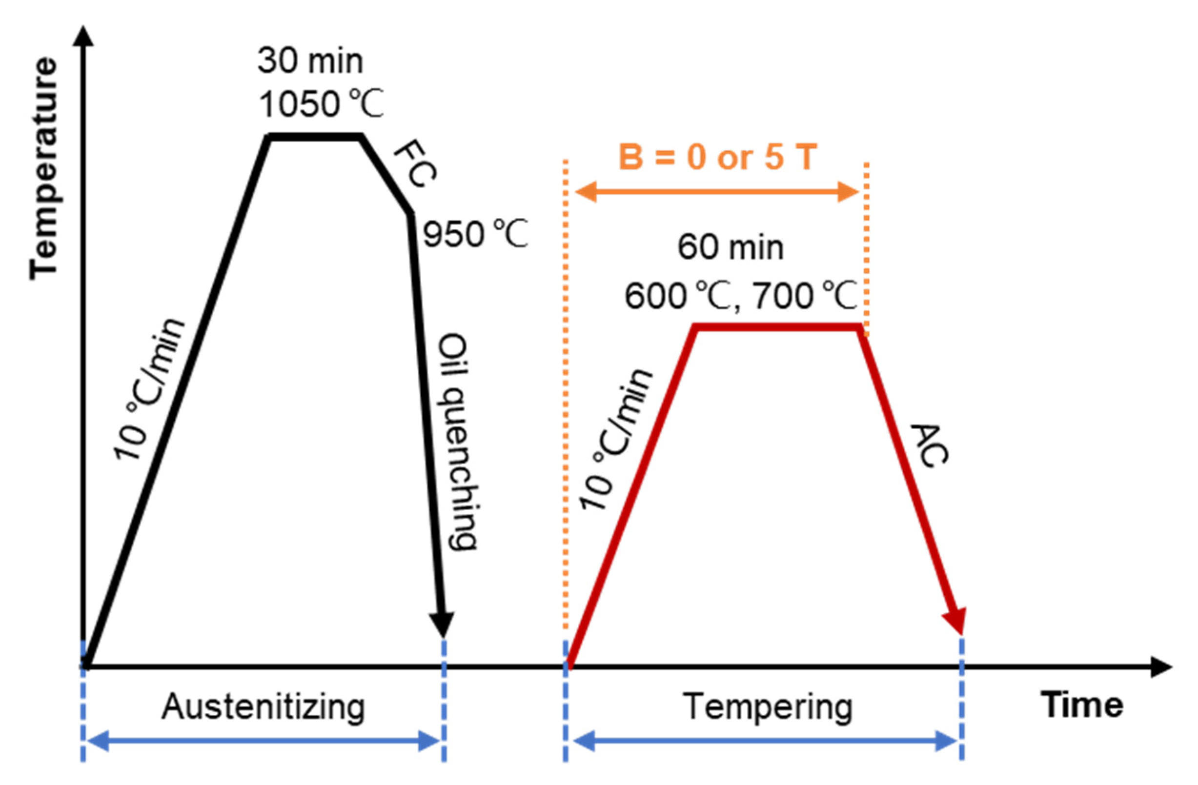
2. Materials and Methods
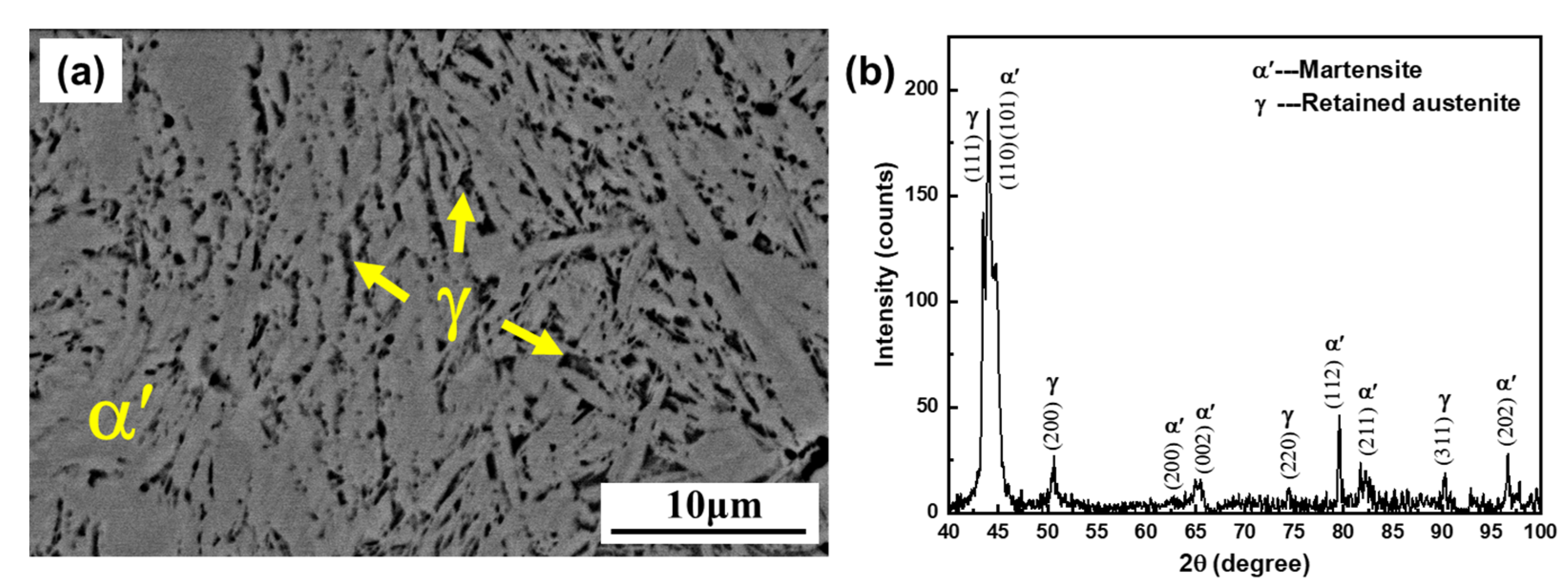
The GCr15 bearing steel was used, and its chemical composition is presented in Table 1. The samples, with dimensions of 7 mm in height and an 8 mm diameter, were cut from hot-rolled rods with a diameter of 40 mm and were heat-treated with and without an external 5 T HMF.
The heat treatment schedule for the GCr15 bearing steel, as shown in Figure 1, includes two steps, i.e., austenitizing and tempering. The samples were enveloped in the silica tube under a vacuum and were first austenitized at 1050 °C for 30 min in a tubular resistance furnace (Shanghai Yifeng Electric Furnace Co., Ltd., Shanghai, China), furnace cooled (FC) to 950 °C, and then oil quenched. Further, the samples were heated at a rate of 10 °C/min, tempered at a given temperature (e.g., 600 and 700 °C) for 60 min with or without an HMF of 5 T, and air-cooled (AC) to room temperature. During tempering, the samples were placed in a central region with a uniform magnetic field intensity and temperature.
The heat-treated samples were ground, polished, and etched with a mixture of 4% nitric acid and alcohol for 10~15 s at room temperature. The microstructures were observed using a scanning electron microscope (SEM, FEI Quanta450 FEG, FEI Inc., Hillsboro, OR, USA). Retained austenite and carbide distribution were measured using Image Pro Plus 6.0 software (Media Cybernetics, Rockville, MD, USA). More than 15,000 carbide particles were measured in the tempered samples. The average Vickers hardness was determined from six randomly selected positions of each sample.
The samples for X-ray diffraction (XRD, Bruker D8 Advance, Bruker GmbH, Karlsruhe, Germany) analysis were prepared through grinding and polishing. Mechanical polishing with a 0.05 µm alumina suspension was used to remove the stress on the surface. The XRD experiments were performed at a scan speed of 1 °/min. The Modified Williamson–Hall (MWH) method [31,32,33] was used to evaluate the dislocation density in the sample. To determine the diffraction angle (θ) and the full width at half maximum (FWHM) of each diffraction peak, the diffraction profiles of the martensitse or ferrite were fitted by the Lorentzian and pseudo-Voigt functions, respectively. The values of FWHM and θ can be used to calculate the dislocation density based on the MWH equation [27,34]:
( Δ K g D ) 2 K 2   B M 2 ρ C ¯ h 00 ( 1 q H 2 )
where Δ K = 2 c o s θ ( Δ θ ) / λ , K = 2 s i n θ / λ , B = π b 2 / 2 , and g is a constant. D, Δ θ ,   λ , b, and ρ represent the average crystallite size, FWHM, wavelength of the X-ray, magnitude of the Burgers vector (for α-Fe b = 0.284 nm [35]), and the dislocation density, respectively. The value of λ is 0.154056 nm for Cu radiation. M is a constant, which was taken as 1.4 [36] and 1 [37] in this study for quenched and tempered samples, respectively. The dislocation contrast factor C ¯ for a (h k l) reflection can be obtained from the following equation [36]:
C ¯ = C ¯ h 00 ( 1 q H 2 )
H 2 = h 2 k 2 + k 2 l 2 + h 2 l 2 ( h 2 + k 2 + l 2 ) 2
where C ¯ h 00 is a constant and the value for iron-based materials is 0.285 [31], and q represents the dislocation characteristics [32]. By linearly fitting the relationship between the left-side term of Equation (1) and H 2 , the slope and interlope can be obtained, Further, the dislocation density can be calculated.

3. Results

The micrograph of the as-quenched GCr15 bearing steel is shown in Figure 2a. It can be seen that the microstructure consists of martensite (α′) and retained austenite (γ). The carbides have been completely dissolved in the matrix. Figure 2b displays the XRD patterns of the quenched sample, which further confirms that there are only two phases of martensite and the retained austenite. The statistical analysis shows that the volume fraction of the retained austenite is approximately 18.9%.
Figure 3 shows the SEM images of the samples tempered in different conditions. When the sample was tempered at 600 °C for 60 min without the HMF, the microstructure is mainly lath-like with a few TS structures (Figure 3a, indicated by yellow arrows). When the tempering temperature increases to 700 °C, the amount of the TS structures distinctly increases. However, when the HMF is applied, the TS structures are almost invisible at a lower temperature (Figure 3b). The number of structures in the absence of the HMF is larger than that with the HMF (Figure 3a–d). Additionally, the morphology of carbides changed from strips to short rods or granules. To quantify the distribution of carbides, the mean diameter and the density of the carbides were measured using Image Pro Plus software, as shown in Figure 4. The size of most of the carbides in the sample tempered at 700 °C are relatively small, with average carbide diameters of 234 nm and 203 nm without and with the HMF, respectively. In comparison, the carbides in the samples tempered with the HMF are finer, their quantity is larger, and the volume fraction is smaller.
Figure 5 exhibits the XRD patterns of samples tempered under different conditions. It can be seen that the matrix of the as-quenched samples is transformed from martensite to ferrite after high-temperature tempering. Compared with the as-quenched samples, tempering results in narrower and stronger diffraction peaks for the ferrite and clearer peaks for the martensite. To quantify the effect of the HMF on the peak intensity, the heights of the α(110) and α′(202) peaks with and without the HMF were compared, as shown in Figure 6. For the (110) peak, the increase in tempering temperature results in a slight increase in the height of the peak, while the height of the (202) peak decreases. However, at the same temperature, the application of the HMF leads to stronger diffraction peaks irrespective of peaks and phases.
Further, the θ and FWHM fitted by the Lorentzian function and the pseudo-Voigt function, respectively, are shown in Table 2. Correspondingly, the dislocation densities calculated using the MWH method are illustrated in Figure 7 and Table 3. It is seen that the dislocation densities in the tempered samples decrease by approximately two orders of magnitude, i.e., from 1016 to 1014, in comparison with that in the as-quenched sample. This is in the same order of magnitude as the dislocation densities obtained by Takebayashi [38], Das Bakshi [33], and Wu et al. [26] for the as-quenched and high-temperature tempered steels. For the tempered samples, there is a difference in the dislocation densities obtained by the two functions; however, the dislocation densities of the samples with an HMF are higher than those without an HMF. For example, at 600 °C, the dislocation density obtained by the Lorentzian function increases from 2.36 × 10¹⁴/m2 in 0 T to 3.01 × 10¹⁴/m2 in 5 T.
Figure 8 shows the Vickers hardness of the samples tempered with and without the HMF. The mean Vickers hardness of the as-quenched sample is 781.6 HV. The hardness significantly decreases after tempering. The higher the tempering temperature, the lower the hardness. At the same tempering temperature, the Vickers hardness of the sample in the HMF is higher than that without an HMF. For example, the mean Vickers hardness of the sample tempered at 600 °C increased from 384.8 in 0 T to 397.0 HV in 5 T.

4. Discussion

The present results show that the HMF during high-temperature tempering slowed down the formation of TS structures, increased the number density of carbides, and reduced the mean diameter and the volume fraction of carbides. Additionally, the high-temperature tempering in the HMF resulted in stronger diffraction peaks and higher dislocation densities with respect to the case of no HMF. The high-temperature tempering in the HMF led to an increase in hardness. The reasons for the change in microstructures and mechanical properties of GCr15 after high-temperature tempering in the HMF are discussed in the following.

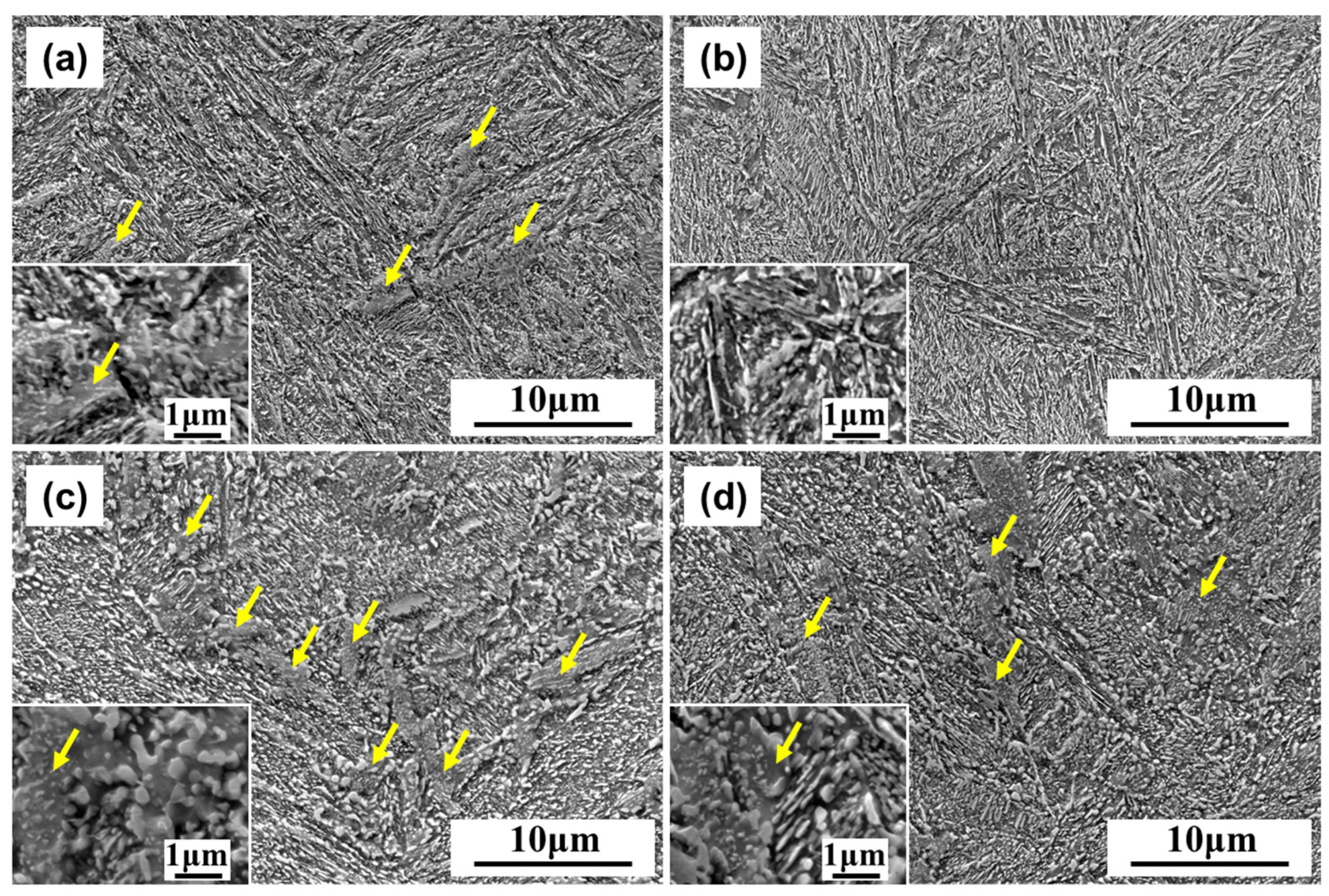
4.1. Microstructure Evolution

It is realized that TS structures with granular carbides distributed in the ferrite matrix can be obtained [6,30] when the as-quenched high-carbon steel is tempered at a high temperature. In this work, the block-like structure in Figure 3 is the TS. As the tempering temperature increased from 600 to 700 °C, the TS structures increased irrespective of the HMF. At the same temperature, the number of TS structures without the HMF is more than that with the HMF. Thus, the application of the HMF has a significant impact on retarding the formation of TS structures. It has been observed that the HMF has a delayed effect on the recovery and recrystallization of cold-rolled steels [39,40]. Zhang et al. [41] attributed this phenomenon to the influence of the magnetic order on diffusion or the obstructive effect of the magnetic domain walls, which reduced the mobility of grain boundaries and thus delayed recovery and recrystallization. In fact, the HMF has been demonstrated to significantly hinder diffusion [42,43,44], which is responsible for the reduction in the number of TS structures.

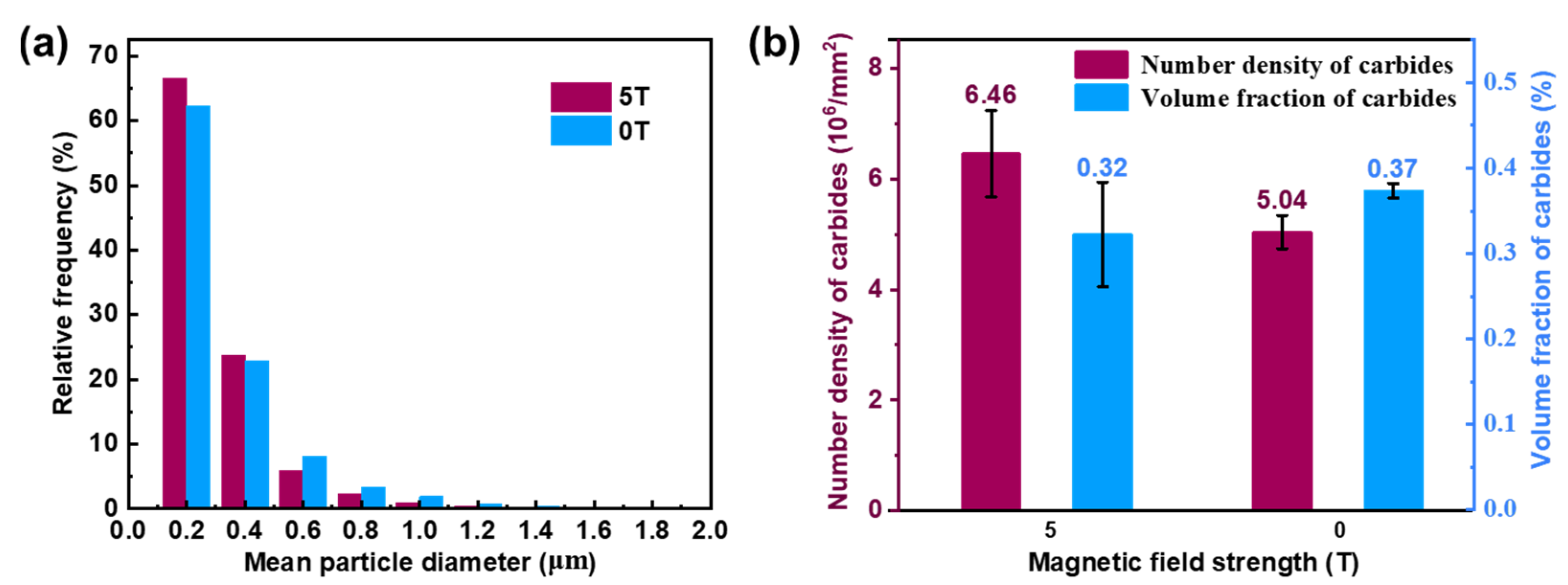
4.2. Carbide Distribution

As mentioned above, the high-temperature tempering of high-carbon steel is accompanied by the precipitation and coarsening of carbides [6,30,41]. In comparison, the tempering in the HMF results in the smaller mean size of the carbides and higher density (Figure 4). Based on the classical nucleation theory, the nucleation rate in the HMF can be described as [26]:
N = N 0 exp ( Q R T ) exp ( Δ G * + Δ G M * R T )
where N0 is a constant. Q, R, and T represent the activation energy for diffusion, the gas constant, and the absolute temperature. Δ G M * and Δ G * are the additional nucleation barrier induced by the HMF and the nucleation barrier in the absence of the HMF, respectively. Δ G * + Δ G M * is expressed as:
Δ G * + Δ G M * = C σ 3 ( Δ G V + Δ G M ) 2
where C is a constant, σ is the interfacial energy between the matrix and carbide, and Δ G V and Δ G M are the change in the chemical free energy and in magnetic free energy induced by the HMF, respectively. Δ G V and Δ G M in Equation (5) have the same sign and are both negative [22,45].   Δ G M can be written as
Δ G M = 0 H M . d H
where M and H represent the magnetization of the phase and the magnetic field strength, respectively.
When an HMF is applied, Δ G M results in a reduction in the total change in Gibbs free energy, resulting in a reduction in the total nucleation barrier Δ G * + Δ G M * in Equation (5). As a result, the nucleation rate N is higher than that without an HMF, which increases the density of the precipitates. This is consistent with the experimental observation that the density of the carbides increases from 5.04 × 10⁶/mm2 in 0 T to 6.46 × 10⁶/mm2 in 5 T. With the precipitation of carbides, the lattice distortion caused by carbon atoms decreases, and the diffraction peaks become narrower and stronger (Figure 5). Therefore, the number of carbides in the HMF increases, resulting in the enhancement of the diffraction peaks of ferrite in the HMF (Figure 5 and Figure 6). Regarding the enhancement of martensite peaks, He et al. [46] conducted in situ neutron diffraction research on the tempering of high-carbon and high-chromium steel at high temperatures and found that metastable retained austenite transformed into martensite at high temperatures, resulting in a significant enhancement of martensite peaks. According to Equation (6), when the magnetic field strength H is constant, the change in free energy is determined by the magnetization strength M . At the experimental temperature, the magnetization of ferromagnetic martensite is much higher than that of paramagnetic austenite [47], which is conducive to the decomposition of the retained metastable austenite and the formation of martensite.
Furthermore, it is well known that carbide growth is a diffusion-controlled process, during which small particles merge to form large particles [48]. It was found that the distortion of the lattice by the HMF makes diffusion more difficult [44], thus hindering the coarsening of the carbides. In addition, the carbides in the TS structures are granular and coarse, and the HMF hindered the diffusion to slow the growth of the TS structures, which is also conducive to the reduction of the mean diameter of carbides. As a result, the average size and the volume fraction of the carbides in the sample tempered in the HMF were smaller than those without the HMF (Figure 4a, b).

4.3. Dislocation Density

As we know, dislocations and precipitates play a vital role in terms of the strength of steels [26,49]. Hard carbides (hardness > 700 HV [50]) precipitate in the soft matrix phase, such as ferrite (130 HV [51]), conforming to the Orowan strengthening mechanism [26,52]. From the experimental results, the HMF leads to the increase in dislocation density in the tempered samples, e.g., the dislocation densities obtained by the pseudo-Voigt function from 2.29 × 10¹⁴ m−2 in 0 T to 2.78 × 10¹⁴ m−2 in 5 T at 700 °C. For precipitates, the density of the carbides increases from 5.04 × 10⁶/mm2 in 0 T to 6.46 × 10⁶/mm2 in 5 T. The change in dislocation density is the result of the carbide–dislocation interaction [26].
Many studies showed that the interaction between dislocations and carbides originates from the stress field induced by the precipitates [43,53,54]. Dislocation bending between pinning points is crucial for dislocation–precipitation interactions in steel and iron materials [55]. Based on the dislocation line tension theory, critical unpinning stress τ under a magnetic field adopts the following formula [26]:
τ = μ b 2 π L [ ln ( D i 1 + L 1 ) 1 + C ]
where μ and b represent the shear modulus and Burgers vector, respectively. Di is the obstacle diameter obtained from experimental results and C is a constant (for impenetrable obstacles, C = 0.7 [26]). The distance between two adjacent precipitates (L) can be expressed as [54]
L = D i 2 × ( 2 π 3 f ) 1 / 2
where f is the carbide volume fraction. The calculated internal distances L between the two precipitates were approximately 277 nm for 0 T and 258 nm for 5 T, respectively. Correspondingly, the calculated critical unpinning stress τ is approximately 86 MPa and 90 MPa, respectively. Hence, a smaller internal distance L led to a larger critical unpinning stress τ, which resulted in the accumulation of dislocations in front of carbides. This explains the increase in dislocation density caused by the application of the HMF, as exhibited in Figure 7. Similar phenomena have been reported in previous studies. Wang et al. [26] performed tempering of the low-carbon steel 12Cr in a 12 T HMF at 700 °C. It was found that the density of carbides increased from 3.64 × 10⁶/mm2 to 8.80 × 10⁶/mm2, and the corresponding dislocation density increased from 0.56 × 10¹⁴ m−2 to 1.18 × 10¹⁴ m−2. The number density and the dislocation density both increased by more than 2 times. However, in this work, the number density of carbides and the dislocation density are not doubled by the HMF. On the one hand, according to Equations (4) and (6), the difference in magnetic field strength (5 T vs. 12 T) weakens the magnetic field-induced carbide precipitation. On the other hand, the mean diameter of carbides is only 60 nm for the low-carbon steel in [26], while it is more than 200 nm for the high-carbon steel in this work, that is, the coarsening of the carbides weakens the difference in the critical unpinning stress.
In addition, when the tempering temperature increases, the dislocation movement is intensified [56], the magnetization of the HMF is weakened [57], the dislocation density is significantly reduced, and the difference in the dislocation density with and without the HMF is also reduced.

4.4. Mechanical Properties

The hardness of the material is closely related to the dislocation density [33,58,59]. The Vickers hardness due to dislocation strengthening, H V ρ , is expressed by the following equation [58]:
H V ρ = 3 σ 0 + 3 ω μ b ρ 1 / 2
where σ 0 is the yield strength and ω, μ, b, and ρ are the constant, shear modulus, Burgers vector, and dislocation density, respectively. According to Equation (9), the Vickers hardness has a positive linear relationship with the dislocation density. Thus, the higher dislocation density in the HMF led to a larger hardness value.
Additionally, the hardness is related to the precipitation of carbides, and the precipitation strengthening ( σ c ), in MPa, can be calculated by the Ashby–Orowan equation [60]:
σ c = 0.538 · μ b · f 1 / 2 D i l n ( D i 2 b )
The hardness of the material is generally 3 times its corresponding tensile strength [58]. Hence, Equation (10) can be written in another form, as follows:
H V c = 1.614 · μ b · f 1 / 2 D i l n ( D i 2 b )
where H V c represents the Vickers hardness contributed to by precipitation strengthening. For steels, μ is 81,600 MPa [60], and combined with the carbide volume fraction and mean diameter in Figure 4, the calculated values of H V c were 58.8 HV for 0 T and 61.5 HV for 5 T, respectively. Obviously, the HMF enhanced the precipitation strengthening and slightly increased Vickers hardness, which is attributed to the reduction in the mean diameter of the carbides by the HMF.

5. Conclusions

The microstructures and mechanical properties after high-temperature tempering of the GCr15 bearing steel with and without an HMF of 5 T were investigated. The main conclusions are summarized as follows:
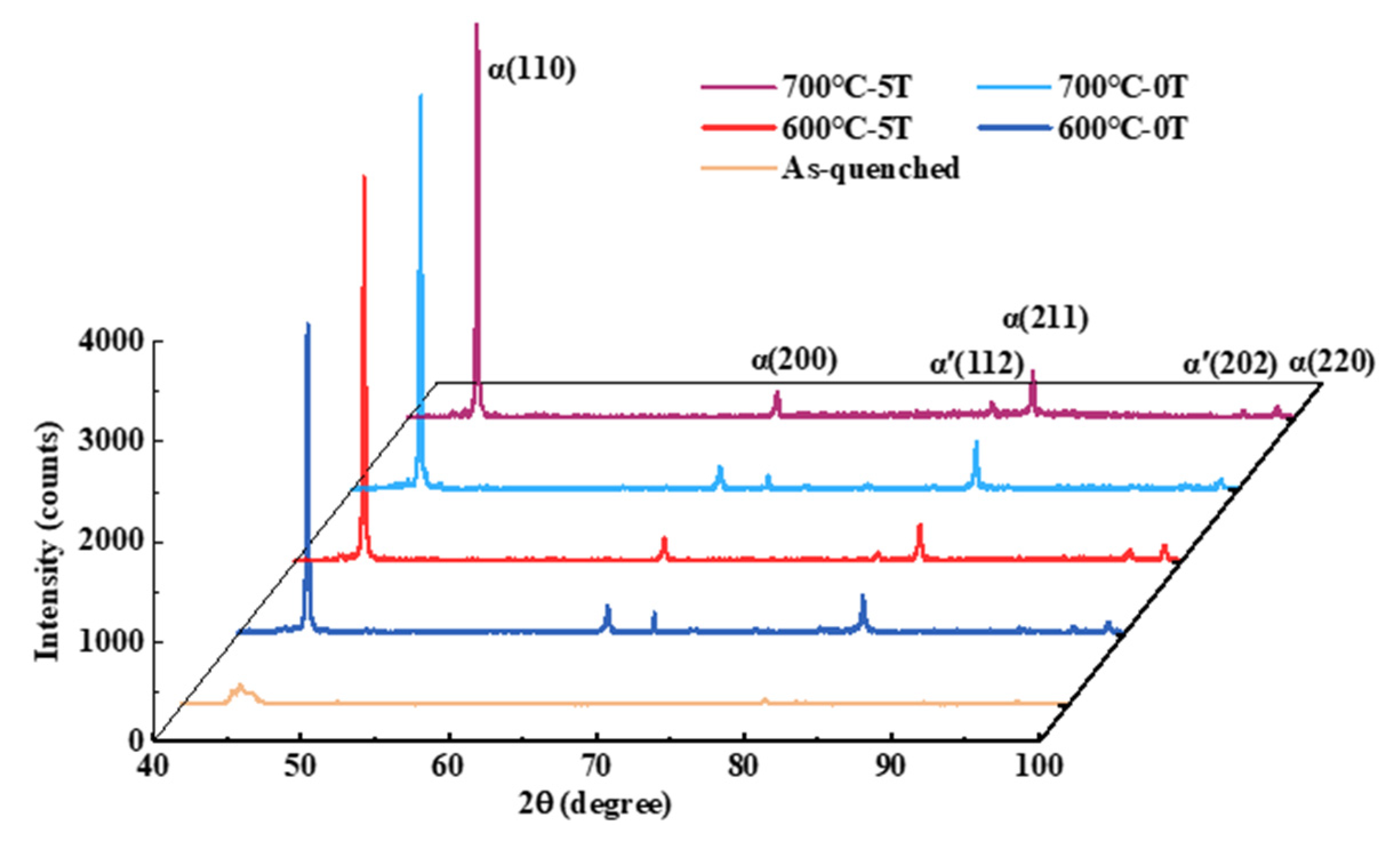
  • The HMF slowed down the growth of the TS structures at the stage of high-temperature tempering, which is attributed to the decrease in diffusivity in the HMF.
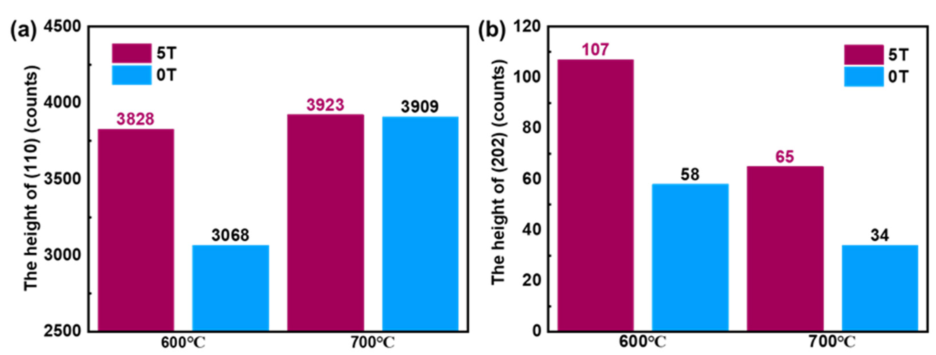
  • During high-temperature tempering, the HMF increased the density of carbides and reduced the average size and volume fraction of carbides. It is shown that the HMF reduces the nucleation barrier of carbides and promotes the density of carbides. Additionally, the hinderance of the HMF to diffusion leads to the smaller mean size and volume fraction of carbides.
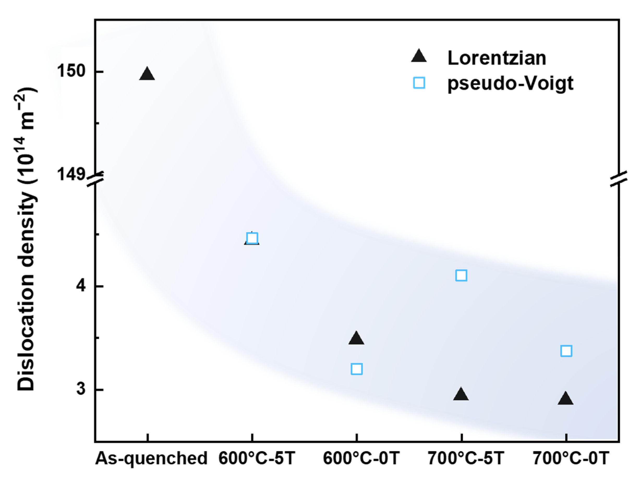
  • During high-temperature tempering, the dislocation density of the sample in the HMF increased. With the application of the HMF, the density of carbides increases. The average interparticle distance decreases, dislocations accumulate in front of carbides, and thus the dislocation density increases.
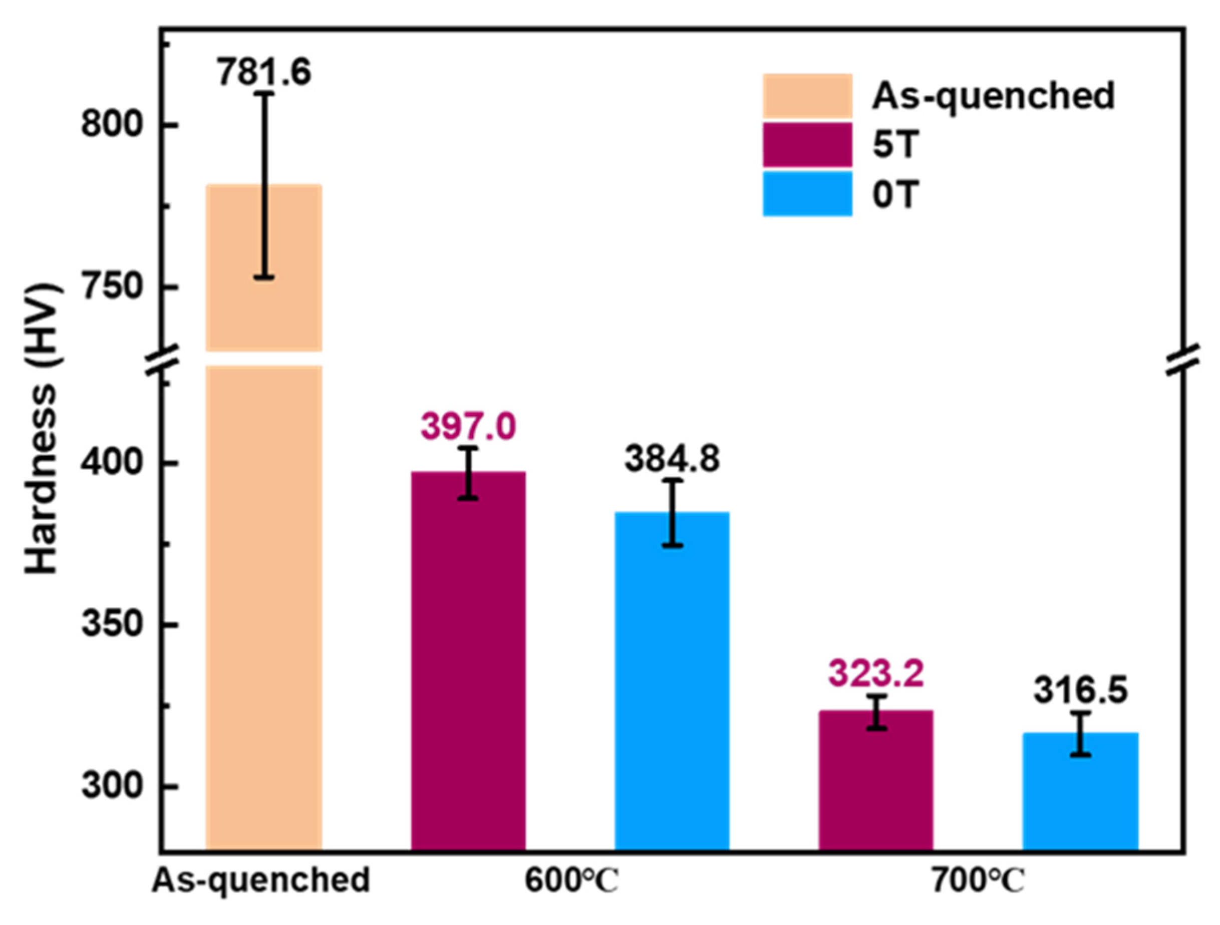
  • The HMF in combination with high-temperature tempering leads to a higher Vickers hardness, which is due to the increase in the dislocation density and the refinement of carbides.

Author Contributions

Conceptualization, Z.R.; methodology, Z.Z., W.X. and J.W.; formal analysis, C.H.; validation, S.C. and F.Z.; writing, Y.L. All authors have read and agreed to the published version of the manuscript.

Funding

This work was supported financially by the Shanghai Sailing Program (No. 21YF1413000), the Shanghai Dawn Scholar Plan (No. 20SG42), and the Shanghai Venus Plan (No. 20QA1403800).

Data Availability Statement

Not applicable.

Conflicts of Interest

The authors declare no conflict of interest.

References

  1. Bhadeshia, H.K.D.H. Steels for bearings. Prog. Mater. Sci. 2012, 57, 268–435. [Google Scholar]
  2. Fu, J. Microstructure and corrosion behavior of hot-rolled GCr15 bearing steel. Appl. Phys. A 2016, 122, 416. [Google Scholar] [CrossRef]
  3. Chen, Q.W.; Zhu, G.H.; Cao, S.M.; Zhao, A.M. Quick Spherodizing in GCr15 Steel by Mechanism of Divorced Eutectoid. Adv. Mater. Res. 2011, 295–297, 515–519. [Google Scholar] [CrossRef]
  4. Qian, D.S.; Yang, J.; Mao, H.J.; Hua, L. Experiment study on warm ring rolling of 52100 bearing steel coupling microstructure spheroidisation. In Proceedings of the International Conference on the Technology of Plasticity, ICTP 2017, Cambridge, UK, 17–22 September 2017. [Google Scholar]
  5. Zhang, M.-X.; Kelly, P. Crystallography of spheroidite and tempered martensite. Acta Mater. 1998, 46, 4081–4091. [Google Scholar] [CrossRef]
  6. Zhang, C.C.; Yi, X.L.; Yuan, Q.Q.; Wang, L. Microstructure and Mechanism of Three Spheroidizing Treatment for the Carbide of GCr15 Steel. Adv. Mater. Res. 2012, 476–487, 351–356. [Google Scholar] [CrossRef]
  7. Pandey, C.; Giri, A.; Mahapatra, M.M. Evolution of phases during tempering of P91 steel at 760 for varying tempering time and their effect on microstructure and mechanical properties. Mater. Sci. Eng. A 2016, 664, 58–74. [Google Scholar] [CrossRef]
  8. Su, S.; Song, R.; Chen, C.; Wang, J.; Zhang, Y. The novel process of spheroidizing-critical annealing used to optimize the properties of carburized steel and its effect on hardening mechanism of quenching and tempering. Mater. Sci. Eng. A 2019, 765, 138322. [Google Scholar] [CrossRef]
  9. Schino, A.D. Analysis of phase transformation in high strength low alloyed steels. Metalurgija 2017, 56, 349–352. [Google Scholar]
  10. Tong, Z.; Zhou, G.; Zheng, W.; Zhang, H.; Zhou, H.; Sun, X. Effects of Heat Treatment on the Microstructure and Mechanical Properties of a Novel H-Grade Sucker Rod Steel. Metals 2022, 12, 294. [Google Scholar] [CrossRef]
  11. Pandey, C.; Giri, A.; Mahapatra, M.M. Effect of normalizing temperature on microstructural stability and mechanical properties of creep strength enhanced ferritic P91 steel. Mater. Sci. Eng. A 2016, 657, 173–184. [Google Scholar] [CrossRef]
  12. Kim, K.-H.; Park, S.-D.; Kim, J.-H.; Bae, C.-M. Role of spheroidized carbides on the fatigue life of bearing steel. Met. Mater. Int. 2012, 18, 917–921. [Google Scholar] [CrossRef]
  13. Joo, H.D.; Kim, S.U.; Shin, N.S.; Koo, Y.M. An effect of high magnetic field on phase transformation in Fe–C system. Mater. Lett. 2000, 43, 225–229. [Google Scholar] [CrossRef]
  14. Ludtka, G.M.; Jaramillo, R.A.; Kisner, R.A.; Nicholson, D.M.; Wilgen, J.B.; Mackiewicz-Ludtka, G.; Kalu, P.N. In situ evidence of enhanced transformation kinetics in a medium carbon steel due to a high magnetic field. Scr. Mater. 2004, 51, 171–174. [Google Scholar] [CrossRef]
  15. Zhang, Y.; He, C.; Zhao, X.; Zuo, L.; Esling, C. Thermodynamic and kinetic characteristics of the austenite-to-ferrite transformation under high magnetic field in medium carbon steel. J. Magn. Magn. Mater. 2005, 294, 267–272. [Google Scholar] [CrossRef]
  16. Shimizu, K.I.; Kakeshita, T. Effect of magnetic fields on martensitic transformations in ferrous alloys and steels. ISIJ Int. 1989, 29, 97–116. [Google Scholar] [CrossRef]
  17. Choi, J.-Y.; Fukuda, T.; Kakeshita, T. Effect of magnetic field on isothermal martensitic transformation in a sensitized SUS304 austenitic stainless steel. J. Alloys Compd. 2013, 577, S605–S608. [Google Scholar] [CrossRef]
  18. Chen, J.H.; Zhou, X.L.; Meng, L.; Liu, W. Inner Connection of Bainite and Pearlite Transformation in Steels. Adv. Mater. Res. 2014, 900, 64–67. [Google Scholar] [CrossRef]
  19. Dong, B.Q.; Hou, T.P.; Wu, K.M.; You, Z.Q.; Li, Z.H.; Zhang, G.H.; Lin, H.F. Low-temperature nanostructured bainite transformation: The effect of magnetic field. Mater. Lett. 2019, 240, 66–68. [Google Scholar] [CrossRef]
  20. Ohtsuka, H.; Hao, X.J.; Wada, H. Effects of Magnetic Field and Prior Austenite Grain Size on the Structure Formed by Reverse Transformation from Lath Martensite to Austenite in an Fe-0.4C Alloy. Mater. Trans. 2005, 44, 7–15. [Google Scholar] [CrossRef] [Green Version]
  21. Zhang, X.; Wang, S.; Zhang, Y.; Esling, C.; Zhao, X.; Zuo, L. Carbon-content dependent effect of magnetic field on austenitic decomposition of steels. J. Magn. Magn. Mater. 2012, 324, 1385–1390. [Google Scholar] [CrossRef]
  22. Zhang, Y.; He, C.; Zhao, X.; Zuo, L.; Esling, C.; He, J. New microstructural features occurring during transformation from austenite to ferrite under the kinetic influence of magnetic field in a medium carbon steel. J. Magn. Magn. Mater. 2004, 284, 287–293. [Google Scholar] [CrossRef]
  23. Zhang, Y.D.; Esling, C.; Gong, M.L.; Vincent, G.; Zhao, X.; Zuo, L. Microstructural features induced by a high magnetic field in a hypereutectoid steel during austenitic decomposition. Scr. Mater. 2006, 54, 1897–1900. [Google Scholar] [CrossRef]
  24. Zhang, X.X.; Zhang, Y.D.; Gong, M.L.; Esling, C.; Zhao, X.; Zuo, L. Effects of a High Magnetic Field on Austenite Decomposition in High Purity Fe-1.1C (wt.%) Alloy. Mater. Sci. Forum 2011, 702–703, 60–63. [Google Scholar] [CrossRef]
  25. Hou, T.P.; Wu, K.M.; He, G. Effect of tempering temperature on carbide precipitation behaviours in high strength low alloy steel under high magnetic field. Mater. Sci. Technol. 2014, 30, 900–905. [Google Scholar] [CrossRef]
  26. Wu, G.H.; Hou, T.P.; Wu, K.M.; Chen, L. Influence of high magnetic field on carbides and the dislocation density during tempering of high Chromium-containing steel. J. Magn. Magn. Mater. 2019, 479, 43–49. [Google Scholar] [CrossRef]
  27. Wang, F.; Qian, D.; Hua, L.; Mao, H.; Xie, L.; Song, X.; Dong, Z. Effect of high magnetic field on the microstructure evolution and mechanical properties of M50 bearing steel during tempering. Mater. Sci. Eng. A 2020, 771, 138623. [Google Scholar] [CrossRef]
  28. Hou, T.P.; Li, Y.; Wu, K.M. Effect of high magnetic field on alloy carbide precipitation in an Fe–C–Mo alloy. J. Alloys Compd. 2012, 527, 240–246. [Google Scholar] [CrossRef]
  29. Wu, G.; Hou, T.; Li, Z.; Chen, L.; Lin, H.; Wu, K. Effect of high magnetic field on the recovery of tempered martensite. Prog. Nat. Sci. Mater. Int. 2020, 30, 134–137. [Google Scholar] [CrossRef]
  30. Samuel, F.; Hussein, A. Tempering of medium-and high-carbon martensites. Metallography 1982, 15, 391–408. [Google Scholar] [CrossRef]
  31. Ungar, T.; Dragomir, I.; Revesz, A.; Borbely, A. The contrast factors of dislocations in cubic crystals: The dislocation model of strain anisotropy in practice. J. Appl. Crystallogr. 1999, 32, 992–1002. [Google Scholar] [CrossRef] [Green Version]
  32. Li, C.; He, S.; Fan, Y.; Engelhardt, H.; Jia, S.; Xuan, W.; Li, X.; Zhong, Y.; Ren, Z. Enhanced diffusivity in Ni-Al system by alternating magnetic field. Appl. Phys. Lett. 2017, 110, 074102. [Google Scholar] [CrossRef]
  33. Das Bakshi, S.; Sinha, D.; Ghosh Chowdhury, S. Anisotropic broadening of XRD peaks of α′-Fe: Williamson-Hall and Warren-Averbach analysis using full width at half maximum (FWHM) and integral breadth (IB). Mater. Charact. 2018, 142, 144–153. [Google Scholar] [CrossRef]
  34. Ungar, T.; Borbely, A. The effect of dislocation contrast on X-ray line broadening: A new approach to line profile analysis. Appl. Phys. Lett. 1996, 69, 3173–3175. [Google Scholar] [CrossRef]
  35. Kunieda, T.; Nakai, M.; Murata, Y.; Koyama, T.; Morinaga, M. Estimation of the system free energy of martensite phase in an Fe-Cr-C ternary alloy. ISIJ Int. 2005, 45, 1909–1914. [Google Scholar] [CrossRef] [Green Version]
  36. HajyAkbary, F.; Sietsma, J.; Böttger, A.J.; Santofimia, M.J. An improved X-ray diffraction analysis method to characterize dislocation density in lath martensitic structures. Mater. Sci. Eng. A 2015, 639, 208–218. [Google Scholar] [CrossRef]
  37. Yadav, S.; EI-Tahawy, M.; Kalácska, S.; Dománková, M.; Yubero, D.C.; Poletti, M.C. Characterizing dislocation configurations and their evolution during creep of a new 12% Cr steel. Mater. Charact. 2017, 134, 387–397. [Google Scholar] [CrossRef]
  38. Takebayashi, S.; Kunieda, T.; Yoshinaga, N.; Ushioda, K.; Ogata, S. Comparison of the Dislocation Density in Martensitic Steels Evaluated by Some X-ray Diffraction Methods. ISIJ Int. 2010, 50, 875–882. [Google Scholar] [CrossRef] [Green Version]
  39. Watanabe, T.; Suzuki, Y.; Tanii, S.; Oikawa, H. The effects of magnetic annealing on recrystallization and grain-boundary character distribution (GBCD) in iron-cobalt alloy polycrystals. Philos. Mag. Lett. 1990, 62, 9–17. [Google Scholar] [CrossRef]
  40. He, C.S.; Zhang, Y.D.; Zhao, X.; Zuo, L.; Esling, C. Effects of a High Magnetic Field on Microstructure and Texture Evolution in a Cold-rolled Interstitial-Free (IF) Steel Sheet during Annealing. Adv. Eng. Mater. 2006, 5, 579–583. [Google Scholar] [CrossRef]
  41. Zhang, Y.; Gey, N.; He, C.; Zhao, X.; Zuo, L.; Esling, C. High temperature tempering behaviors in a structural steel under high magnetic field. Acta Mater. 2004, 52, 3467–3474. [Google Scholar] [CrossRef]
  42. Li, C.; Yuan, Z.; Guo, R.; Xuan, W.; Ren, Z.; Zhong, Y.; Li, X.; Wang, H.; Wang, Q. Reaction diffusion in Ni–Al diffusion couples in steady magnetic fields. J. Alloys Compd. 2015, 641, 7–13. [Google Scholar] [CrossRef]
  43. Li, C.; Yuan, Z.; Fan, Y.; He, S.; Xuan, W.; Li, X.; Zhong, Y.; Ren, Z. Microstructure and mechanical properties of a Ni-based superalloy after heat treatment in a steady magnetic field. J. Mater. Process. Technol. 2017, 246, 176–184. [Google Scholar] [CrossRef]
  44. Feng, L. Effect of Alloying Elements and High Magnetic Field on Pearlite Transformation and Micro-Structure of High Carbon Steel. Ph.D. Thesis, Wuhan University of Science and Technology, Wuhan, China, 2021. [Google Scholar]
  45. Hou, T.P.; Li, Y.; Zhang, J.J.; Wu, K.M. Effect of magnetic field on the carbide precipitation during tempering of a molybdenum-containing steel. J. Magn. Magn. Mater. 2012, 324, 857–861. [Google Scholar] [CrossRef]
  46. He, S. Research of Tempering Behavior of Retained Austenite in High C-High Cr Tool Steel. Master’s Thesis, Wuhan University of Science and Technology, Wuhan, China, 2015. [Google Scholar]
  47. Cullity, B.; Graham, C. Introduction to Magnetic Materials, 2nd ed.; John Wiley & Sons, Inc.: Hoboken, NJ, USA, 2008; p. 148. [Google Scholar]
  48. Krauss, G. Tempering of martensite in carbon steels. In Phase Transformations in Steels; Pereloma, E., Edmonds, D.V., Eds.; Woodhead Publishing: Cambridge, UK, 2012; pp. 126–150. [Google Scholar]
  49. Zurutuza, I.; Isasti, N.; Detemple, E.; Schwinn, V.; Mohrbacher, H.; Uranga, P. Toughness property control by Nb and Mo additions in high-strength quenched and tempered boron steels. Metals 2021, 11, 95. [Google Scholar] [CrossRef]
  50. Bhadeshia, H.K.D.H. Cementite. Int. Mater. Rev. 2019, 65, 1–27. [Google Scholar] [CrossRef] [Green Version]
  51. Kamikawa, N.; Hirohashi, M.; Sato, Y.; Chandiran, E.; Miyamoto, G.; Furuhara, T. Tensile Behavior of Ferrite-martensite Dual Phase Steels with Nano-precipitation of Vanadium Carbides. ISIJ Int. 2015, 55, 1781–1790. [Google Scholar] [CrossRef] [Green Version]
  52. Silva, R.A.; Pinto, A.L.; Kuznetsov, A.; Bott, I.S. Precipitation and grain size effects on the tensile strain-hardening exponents of an API X80 steel pipe after high-frequency hot-induction bending. Metals 2018, 8, 168. [Google Scholar] [CrossRef] [Green Version]
  53. Xiang, Y.; Cheng, L.-T.; Srolovitz, D.J.; Weinan, E. A level set method for dislocation dynamics. Acta Mater. 2003, 51, 5499–5518. [Google Scholar] [CrossRef]
  54. Huang, K.; Marthinsen, K.; Zhao, Q.; Logé, R.E. The double-edge effect of second-phase particles on the recrystallization behaviour and associated mechanical properties of metallic materials. Prog. Mater. Sci. 2018, 92, 284–359. [Google Scholar] [CrossRef]
  55. Szajewski, B.; Pavia, F.; Curtin, W. Robust atomistic calculation of dislocation line tension. Modell. Simul. Mater. Sci. Eng. 2015, 23, 085008. [Google Scholar] [CrossRef] [Green Version]
  56. Zhang, Z.; Hu, Z.; Schmauder, S.; Zhang, B.; Wang, Z. Low cycle fatigue properties and microstructure of P92 ferritic-martensitic steel at room temperature and 873 K. Mater. Charact. 2019, 157, 109923. [Google Scholar] [CrossRef]
  57. Li, Z.; Hou, T.; Wu, G.; Wu, K.; Lin, H. Thermodynamic Analysis for the Magnetic-Field-Induced Precipitation Behaviours in Steels. Metals 2019, 9, 909. [Google Scholar] [CrossRef] [Green Version]
  58. Yin, J.; Umemoto, M.; Liu, Z.G.; Tsuchiya, K. Formation mechanism and annealing behavior of nanocrystalline ferrite in pure Fe fabricated by ball milling. ISIJ Int. 2001, 41, 1389–1396. [Google Scholar] [CrossRef]
  59. Takaki, S.; Masumura, T.; Tsuchiyama, T. Dislocation characterization by the direct-fitting/modified Williamson–Hall (DF/mWH) method in cold worked ferritic steel. ISIJ Int. 2019, 59, 567–572. [Google Scholar] [CrossRef] [Green Version]
  60. Gladman, T. Precipitation hardening in metals. Mater. Sci. Technol. 1999, 15, 30–36. [Google Scholar] [CrossRef]
Figure 1. Heat treatment schedule for the GCr15 bearing steel without and with the HMF.
Metals 12 01293 g001
Figure 2. Microstructure and XRD patterns of the as-quenched GCr15 bearing steel: (a) BSE micrograph, (b) XRD pattern.
Metals 12 01293 g002
Figure 3. SEM micrographs of the GCr15 bearing steel samples tempered at different temperatures without and with an HMF, (a) 600 °C, 0 T, (b) 600 °C, 5 T, (c) 700 °C, 0 T, (d) 700 °C, 5 T, where TS structures marked by the yellow arrows.
Metals 12 01293 g003
Figure 4. The mean diameter (a) and the number density and volume fraction (b) of the carbides in the samples tempered at 700 °C.
Metals 12 01293 g004
Figure 5. XRD patterns of samples tempered in different conditions.
Metals 12 01293 g005
Figure 6. Heights of the diffraction peaks: (a), α(110), (b), α′(202).
Metals 12 01293 g006
Figure 7. Dislocation densities of the heat-treated samples.
Metals 12 01293 g007
Figure 8. Vickers hardness of the heat-treated samples.
Metals 12 01293 g008
Table 1. Chemical composition (wt. %) of the GCr15 bearing steel.
CCrMnSiPSCuVAlFe
0.951.550.400.260.0060.0010.0490.0040.007Bal.
Table 2. θ and FWHM fitted by the Lorentzian function and the pseudo-Voigt function.
Fitting Function(h k l)As-Quenched600 °C-5 T600 °C-0 T700 °C-5 T700 °C-0 T
θFWHMθFWHMθFWHMθFWHMθFWHM
Pseudo-Voigt110--44.730.1444.730.1444.710.1244.700.12
200--65.070.2365.100.2765.070.2565.030.26
211--82.400.2582.380.2382.380.2282.380.21
220--98.970.3098.970.2598.970.2598.980.24
Lorentzian11044.111.4244.720.1344.730.1344.710.1144.700.12
20065.151.0965.060.2365.070.2465.030.2165.000.22
21179.570.1782.380.2482.370.2482.360.2082.360.20
22096.650.2398.960.2898.970.2598.950.2398.960.23
For the as-quenched sample, the corresponding crystal planes are (110), (002), (112), (202) and the pseudo-Voigt function cannot be fitted to obtain the correct values.
Table 3. Dislocation densities (×1014/m2) calculated using different methods.
Material StateLorentzianPseudo-Voigt
As-quenched149.96-
600 °C-5 T3.013.03
600 °C-0 T2.362.17
700 °C-5 T1.992.78
700 °C-0 T1.972.29
Publisher’s Note: MDPI stays neutral with regard to jurisdictional claims in published maps and institutional affiliations.

