Article

Numerical Simulation of the Electromagnetic Dross Removal Technology Applied in Zinc Pot of Hot-Dip Galvanizing Line

1
Iron and Steel Research Institute, Ansteel Beijing Research Institute Co., Ltd., Beijing 102211, China
2
Key Laboratory of Electromagnetic Processing of Materials, Ministry of Education, Northeastern University, Shenyang 110819, China
3
Technology Center, Angang Steel Co., Ltd., Anshan 114009, China
*
Author to whom correspondence should be addressed.
Metals 2022, 12(10), 1714; https://doi.org/10.3390/met12101714
Submission received: 31 August 2022 / Revised: 6 October 2022 / Accepted: 10 October 2022 / Published: 13 October 2022
(This article belongs to the Special Issue Electromagnetic Preparation of Metallic Materials)

Abstract

:
The forming of zinc dross floating on the surface of molten zinc in zinc pot is inevitable during hot-dip galvanizing production. The cleaning of zinc dross has always been a challenge and a difficult problem to solve. Based on the electromagnetic field theory and its application, a new electromagnetic dross removal technology was proposed, and the zinc dross driven by flowing molten zinc was possible to remove in an electromagnetic field circumstance. Through the coupling simulation of electromagnetic field and flow field, the electromagnetic force acting on molten zinc and the flow situation of molten zinc were simulated. The results showed that electromagnetic field can effectively act on the top surface of molten zinc and affect the flow of molten zinc. Different load conditions of electromagnetic field and the distance between the bottom surface of the iron core and the top surface of molten zinc related to zinc dross removal effect were discussed. Finally, the optimal application parameters of the electromagnetic dross removal technology were put forward.

1. Introduction

The demand for galvanized iron (GI) products continues to expand beyond the traditional applications for auto bodies, household appliances, and structural components [1]. Meanwhile, the ever increasing demand for the use of stronger and thinner sheets with a thinner coating has made the galvanizing process more challenging with respect to surface finishing, in particular. As it is known to all, the surface quality of the GI products is correlated with the hot-dip galvanizing process controlling in the hot-dip galvanizing line. The zinc dross forming on the surface of molten zinc in zinc pot is the vital factor damaging the surface quality of the GI products [2]. Dross is formed due to the dissolution of iron which in turn forms solid intermetallic compounds and oxides in the pot. Dross floating on the top of the pot will adhere to the surface of the strip forming zinc dross defects, which seriously affect the surface quality of galvanized products. In addition, dross may also adhere to the zinc pot equipment, affecting the stable operation of the equipment. The zinc dross should be timely removed in order to avoid adhering to the surface of the GI product or blocking off the export of the GI product, which is benefit to improve the quality of the GI products.
It may generates a few tons of zinc dross a day on average for the hot-dip galvanizing line. At present, the prevalent methods removing zinc dross mainly depend on manual or robot operation. For manual dross removal, workers operate the artificial zinc dross removal behavior every 1 or 2 h, and at least 30 min each time. On this condition, the workers bear high labor intensity. At the same time, the noise and high temperature working circumstance around the zinc pot are harmful to the personal health and security. Though there are multiple noteworthy advantages utilizing robot removing zinc dross, the operating space limits its application zone, which still needs cooperate with manual operation. In addition, it is unavoidable inducing the surface fluctuation of molten zinc for both manual and robot zinc dross removal operation, which may lead to serious surface quality problem. To date, the dross removal problem encountered in galvanizing process must be solved and a novel dross removal technology substituting manual and robot operation is urgent.
Facing the zinc dross removal problem and technology challenge, a large number of research and explorations were carried out. In order to predict the distribution and adhesion probability of the intermetallic dross particles to the steel strip surface, Kim Y.H. et al. [3] developed a 3D numerical model to analyze the flow and temperature distributions in the zinc pot of No. 2 CGL of POSCO Kwangyang strip mills. The results manifested that the variation of the steel strip speed did not produce any discernable change in the overall flow pattern of the pot. The strip width significantly changed the flow pattern in the pot. When the strip width was narrow, the flow induced by the rotating sink roll developed more freely and was likely to stir up and disturbed both the bottom and free surface of the pot, which may increase the overall density of the floating dross in the pot. Addressing the problem of dross removal in the galvanizing process requires detailed information of the flow characteristic inside the zinc pot. Lee S.J. et al. [4] constructed a transparent water model of hot-dip galvanizing process, which was to investigate the flow characteristics inside the zinc pot. The results indicated that the flow in the upper area of the exit region was greatly influenced by the operation of the induction heater. When a scraper was attached onto the stabilizing roll, the separated flow from the strip was guided downward and the up-rising flow around the stabilizing roll became slow and tranquil. By attaching baffles near the moving strip in addition to the stabilizing rolls, the flow entrainment into the corner region between the strip and the stabilizing roll was greatly reduced.
For the sake of understanding of flow in the galvanizing bath, particularly under nonisothermal conditions, Hétu J.F. et al. [5] applied a three-dimensional finite-element solution algorithm to predict the velocity and temperature fields. It was found that temperature-induced flow was important, especially close to the inductors and the melting ingot, because of the higher temperature gradients presented in those regions. Thermal effects were also amplified when the inductor was at high capacity, during the ingot melting. Furthermore, in order to predict and to better understand the generation and movement of intermetallic dross particles within certain regions of a typical galvanizing bath, Hétu J.F. et al. [6] simulated the coupled phenomena of momentum, heat, and mass transfer. The numerical simulation showed that the aluminum concentration as precipitated Fe2Al5 increased in the melting-ingot zone, primarily due to the decrease of temperature near the ingot surface and, also, because of the higher aluminum concentration of the ingot. It was clearly shown that the heat input needed to be closely controlled during ingot melting to maintain a stable temperature of the bath. The inherent temperature gradients caused by ingot melting resulted in the precipitation of aluminum as Fe2Al5 in the cold regions of the bath.
Dash S.K. et al. [7] investigated the flow field which was responsible for dross pick up by the strip. The results showed that the flow field without any plate baffle near the strip can induce dross pick up by the strip because there exists self-sustaining vortex near the strip which can feed dross on to the flow again. By placing a parallel plate baffle near the strip the self-feeding vortex could be removed and the flow field became more amenable for galvanizing. Little was known about the trajectory of the dross particles in relation to the pot layout. Vieira R.R. et al. [8] simulated two types of layout to assess how this interferes with the flow of zinc. One type of the layout with side inductors over the strip named pot A, and the other with front inductors to the strip called pot B. It was found that larger particles were easier to precipitate on the bath surface than smaller particles. The results were possible to verify that in pot A there was a potential increase in the risk of the strip dragging dross particles fixed on its surface by the submerged deflector roller and also in the other regions of the strip, which possibly can be changed by altering the distance between the output of the inductors and the strip submerged in the bath. In pot B, a potential increase in the risk of precipitation of top-dross inside the snout was identified, which may be a greater risk since the accumulation of dross inside the snout could prevent the production of materials of any level of superficial quality requirements. In despite of numerous efforts and endeavors aiming at dross removal problem have been done, an effective dross removal technology suiting for industrial application is still in the blank stage. In recent years, many theoretical and experimental research indicate that electromagnetic field provides a new way to solve difficult problems [9], and many significant achievements have been reported [10,11]. Inspired by the driving capability of electromagnetic field to molten metal [12], the authors considered that zinc dross on the top surface of molten zinc could move with flowing molten zinc, and molten zinc could flow driven by electromagnetic field. Thus, most of zinc dross can be removed and sent to a designated spot where the zinc dross can be wipe out by robot operation. In this way, the problem of zinc dross removal was basically solved. Therefore, in the present work, the numerical simulation of the electromagnetic dross removal technology applied in zinc pot of hot-dip galvanizing line was pointed out. High dross removal efficiency and convenience for application were the prominent characteristics of this new technology. With the rapid removal of zinc dross, there was no dross accumulation and the surrounding environment of the zinc pot area can be greatly improved. The application of automation control was more convenient for operating. The electromagnetic field worked just during the de-drossing process, and worked 1–3 min for every operation. In addition, the electromagnetic field was not harmful to the workers’ body and did not affect the operation of the surrounding equipments. Comparing with manual or robot dross removal assignment, a rough estimate of the annual benefit was about 3 million RMB for each galvanized line by utilizing the electromagnetic dross removal technology, and the use of such a solution was competitive. Under the condition of industrial application parameters and considering the influence of current density, frequency, and effective action distance, the numerical simulation calculation was carried out, and the calculation results were analyzed to select the optimum technological application parameters. Furthermore, the flow field in the zinc pot, the fluctuation on the top surface of molten zinc, and the velocity of molten zinc were numerically simulated. Finally, the feasibility of this kind of new technology was evaluated.

2. Mathematical and Physical Model

2.1. Assumptions

With regard to the complex structure of zinc pot and galvanizing process, the following reasonable assumptions were made to simplify the numerical calculation both of the electromagnetic field and flow field:
(1)
Molten zinc was incompressible Newtonian fluids;
(2)
Molten zinc in zinc pot was homogeneous, and parameters such as density and viscosity are set to be constants;
(3)
The flow oscillation influence of molten zinc was not considered;
(4)
The influence of strip movement, sink roll rolling, and movement of the other components were not considered;
(5)
The influence of Joule heat generated by electromagnetic field was ignored;
(6)
The influence of molten zinc flow on the electromagnetic field was ignored.

2.2. Electromagnetic Model

The electromagnetic field was determined by solving Maxwell’s equations:
  × H = J   × E = B t     B = 0
J = σ   ( E + v × B )
B = μ   H
where, H is magnetic field strength, A/m; J is induced current density, A/m2; E is electric field strength, V/m; B is magnetic flux density, T; σ is electric conductivity, S/m; v is velocity of fluid, m/s; μ is permeability, H/m.
After that, the Lorentz force is given by:
F em = J × B

2.3. Fluid Flow Model

In this work, the computational fluid dynamics control equation is mainly the mass conservation equation for fluid, which can be simplified as:
    μ = 0
Fluid momentum conservation follows the Navier-Stokes momentum conservation equation. The change rate of the fluid momentum of infinitesimal body on time equals to the sum of outside forces acting on the infinitesimal body, namely:
( ρ u ) t +     ( ρ μ u ) =     P + ρ g +     μ (   u ) + (   u ) T + F em
where, ρ is density of fluid, kg/m3; u is velocity of fluid, m/s; μ is dynamic viscosity of fluid, N·s/m2; g is gravitational acceleration, m/s2; Fem is magnetic force, N; T is mathematics transposed symbol.
Thus, the fluid flow model chose the k-ε turbulence model [13].
( ρ k ) t + ( ρ ku i ) x i = x j   ( μ + μ t σ k ) k x j + G k     ρ ε
( ρ ε ) t + ( ρ ε u i ) x i = x j   ( μ + μ t σ ε ) ε x j + C 1 ε ε k G k     C 2 ε ρ ε 2 k
μ t = ρ C u k 2 ε
where, ρ is density of fluid, kg/m3; k is turbulent kinetic energy, J; ui is velocity component of fluid, m/s; μ is dynamic viscosity of fluid, N·s/m2; μt is turbulent viscosity, Pa·s; σk is Prandtl number; Gk is the generation item of turbulent kinetic energy induced by average velocity gradient; ε is dissipation rate of turbulent kinetic energy; Cμ, C1ε, C2ε is empirical constant; σs is Prandtl number corresponding to the dissipation rate.

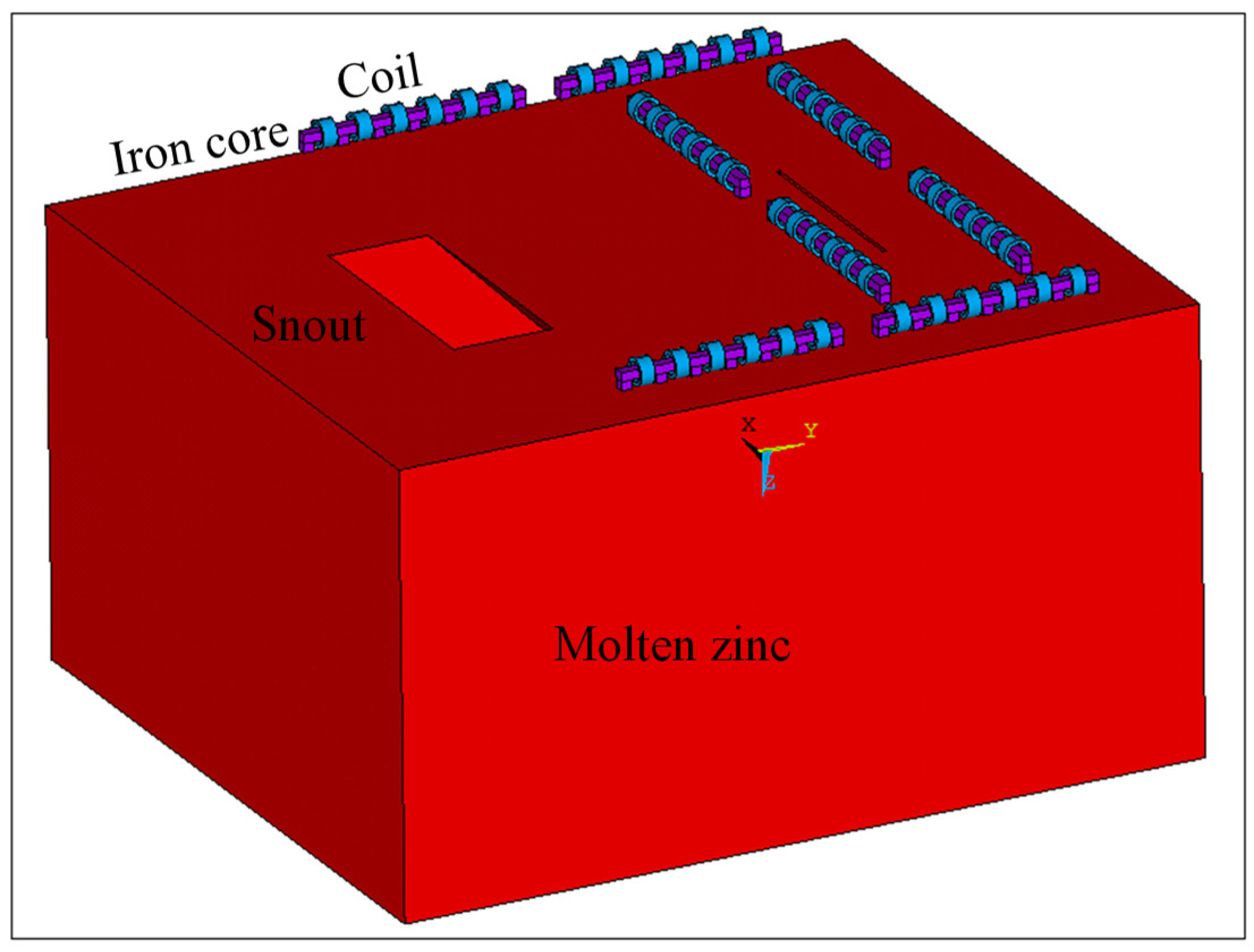
2.4. Geometrical Model and Boundary Conditions

2.4.1. Geometry Model

Figure 1 shows the geometry model for numerical simulation of the electromagnetic dross removal technology applied in zinc pot of hot-dip galvanizing line. Based on the actual dimension of zinc pot for industrial application, six electromagnetic dross removal devices were installed on the top of molten zinc, and each electromagnetic dross removal device had 6 coils around the straight iron core. The electromagnetic device was fed by a three-phase AC power to generate a traveling magnetic field. The dimension of molten zinc was 3958 mm in length, 4558 mm in width, and 2496 mm in thickness. Some other geometric parameters and material properties used in this work were listed in Table 1.

2.4.2. Boundary Conditions

For electromagnetic field simulation, to capture a great part of the magnetic field lines closing in the surrounding air, an air cuboid (5000 mm × 4200 mm × 3000 mm) around the whole geometry model was built. Magnetically flux parallel boundary conditions were employed for the external surfaces of the surrounding air cuboid [14].
For flow field simulation, the initial velocity of molten zinc in mathematical model was 0. The top surface of molten zinc was a free surface, and the other surfaces were assumed as no slip boundaries. In numerical calculation, using an engineering software to calculate the electromagnetic force and its distribution produced by traveling wave magnetic field and acting on molten zinc. Afterwards, the electromagnetic force results were output according to coordinate and read regarding as boundary condition. Then, combining with the fluid momentum equation, the finite element numerical solution was conducted.
In this study, numerical simulation of the electromagnetic dross removal technology applied in zinc pot of hot-dip galvanizing line was divided into two steps. Firstly, Maxwell’s equations were solved to determine the electromagnetic field using the commercial software ANSYS Multiphysics. Secondly, the time-averaged electromagnetic volume force data were loaded into the momentum equation as a source term to simulate the flow behavior in the zinc pot using the software FLUENT.

3. Results and Discussion

3.1. Magnetic Field Distribution

Figure 2 displayed the magnetic field distribution of the coil, the iron core, and the molten zinc parts. As shown in Figure 2a, the magnetic field induced by the coils was mainly distributed in the inner of the coils, and the direction of the magnetic flux density was perpendicular to the coil plane. The magnetic field stimulated by the coils entirely distributed in the iron cores as shown in Figure 2b. The direction of the magnetic flux density in terms of the coil and iron core were consistent. From Figure 2c, it can be seen that the magnetic field mainly formed on the top surface of molten zinc. The direction of the induced magnetic field were controlled by the coils and the iron cores. The induced magnetic field vectors showed similar direction with magnetic field vectors shown in Figure 2a,b.
Furthermore, it can be seen that magnetic flux density distribution was remarkably uniform on the surface of molten zinc shown in Figure 2c, which was about one degree at least bigger than the one apart from the electromagnetic dross removal device.

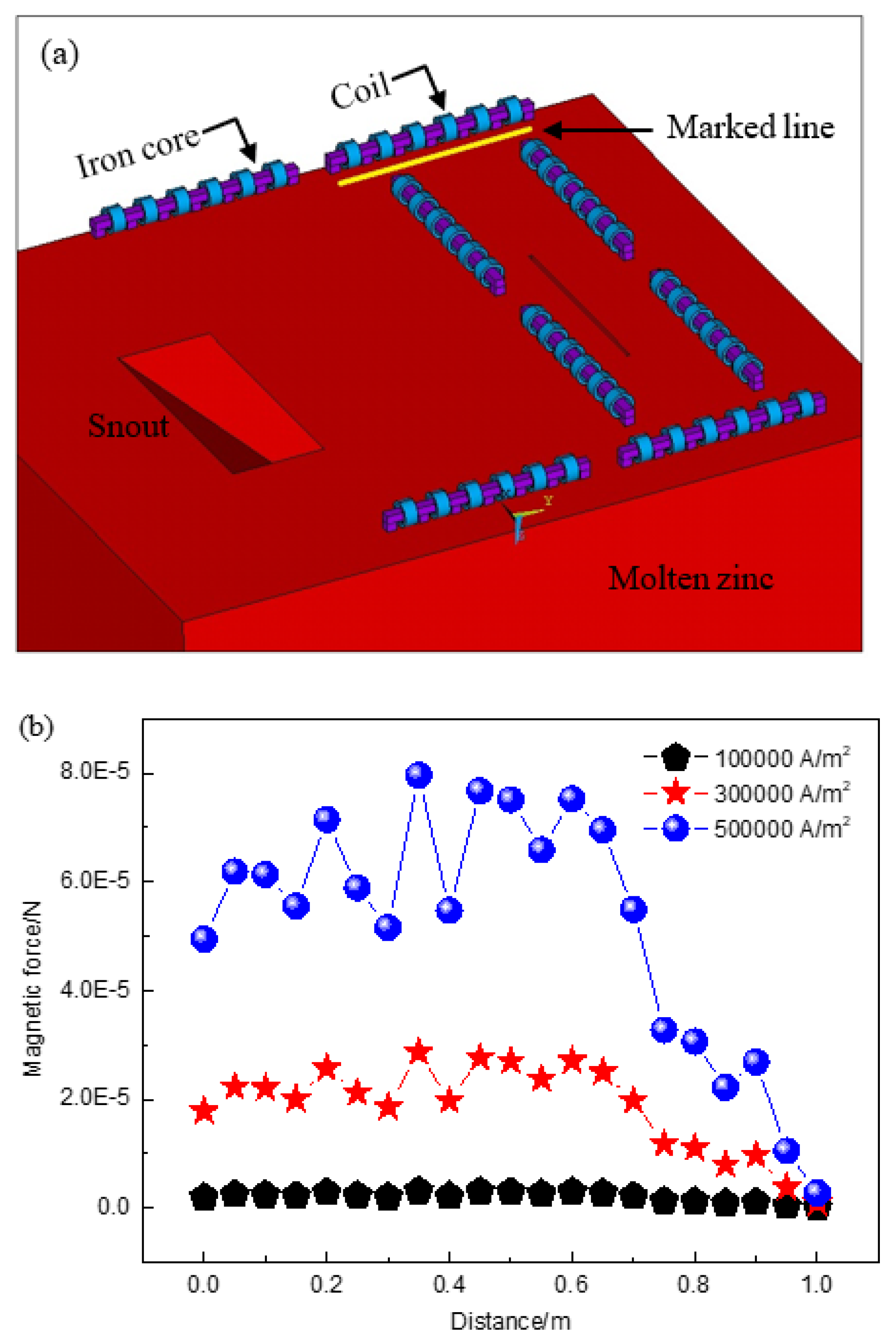
3.2. Effect of Current Density on Electromagnetic Force

The electromagnetic force acting on molten zinc was the key factor which was relate with the dross removal. The electromagnetic force was selected along the axial direction of a selected electromagnetic dross removal device as shown in Figure 3a. The electromagnetic force on the top surface of molten zinc changing with the load current density was shown in Figure 3b.
From Figure 3b, it can be seen that the electromagnetic force on the edge of the electromagnetic dross removal device was smaller than the electromagnetic force in the middle of the electromagnetic dross removal device. It illustrated that the electromagnetic dross removal device mainly made an effective contribution to drive the molten zinc perpendicular distributed under the electromagnetic dross removal device, and the action zone rarely divergent. As the current density changes from 100,000 A/m2 to 500,000 A/m2, the calculated electromagnetic force of molten zinc on the mold surface increase. It can also find that electromagnetic forces calculated at different position were different and the difference were obvious changing with the increase of current density. It illustrated that a bigger current density may result in the top surface fluctuation of molten zinc. As a result, it better to choose a relatively smaller current density, such as 300,000 A/m2.

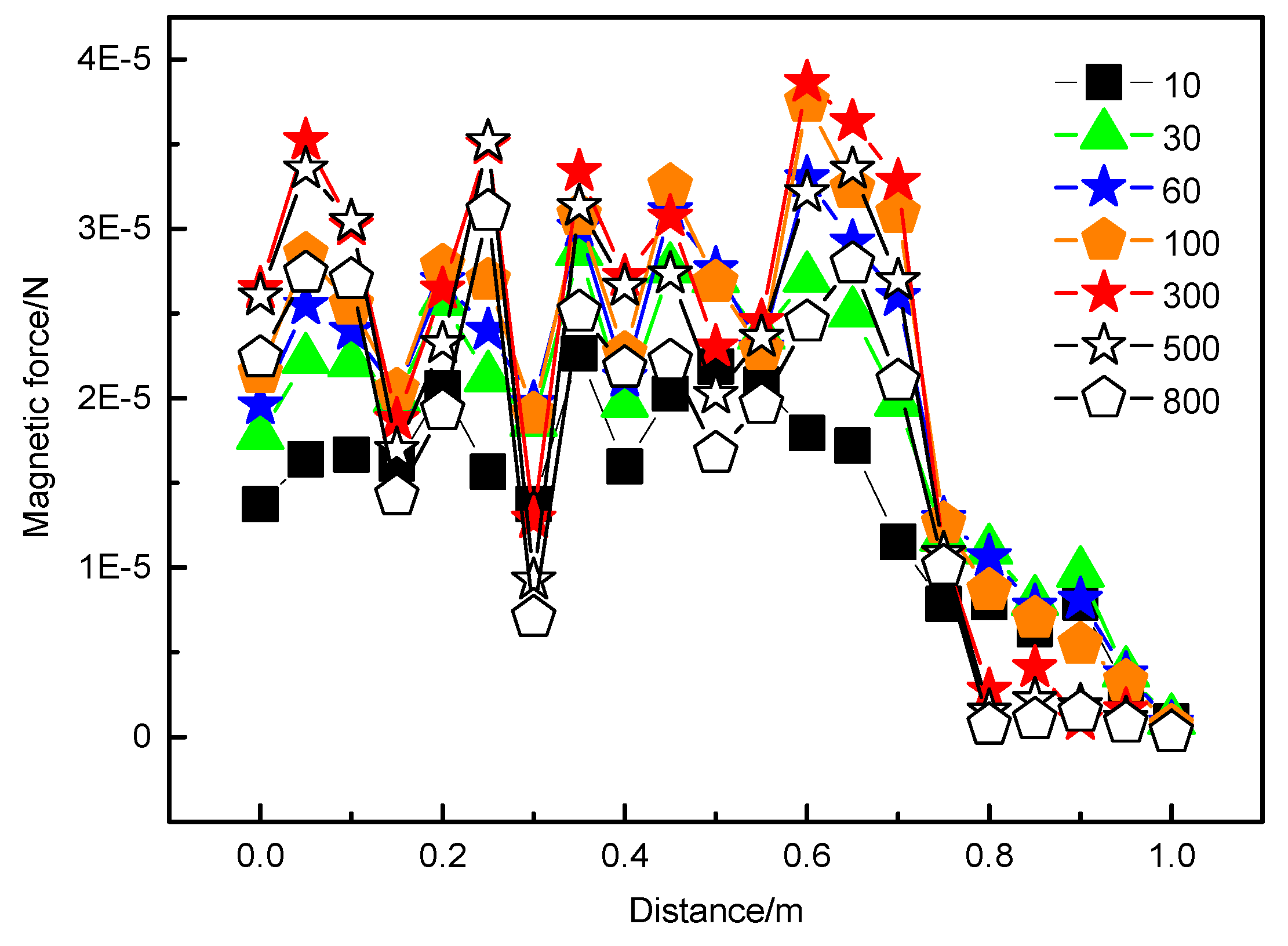
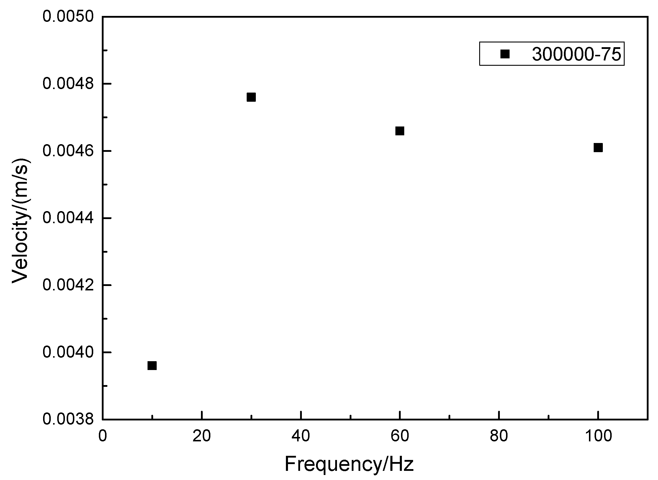
3.3. Effect of Frequency on Electromagnetic Force

The electromagnetic force with a current density of 300,000 A/m2 and different frequency was calculated and the result was shown in Figure 4. The electromagnetic force increase firstly and then decrease as the frequency changing from 10 to 800 Hz. The maximum electromagnetic force can be obtained when the frequency was 300 Hz. It can deduce that electromagnetic force increased with the increase of frequency as the frequency in the range from 10 to 300 Hz. Based on the Skin-effect, on the one hand, bigger frequency was benefit to magnetic field distribution on the top surface of molten zinc and decrease the influence depth and stirring both of which were good for stabilizing the top surface of molten zinc. However, on the other hand, bigger frequency may produce apparently heat effect, which was an unexpected effect as well as led to the energy waste. In addition, comparing the result, it exhibited that there was no magnitude distinction of the magnetic force between a small and a big frequency. Taking a reasonable consideration, the frequency was appropriate to choose a range from 30 to 100 Hz.

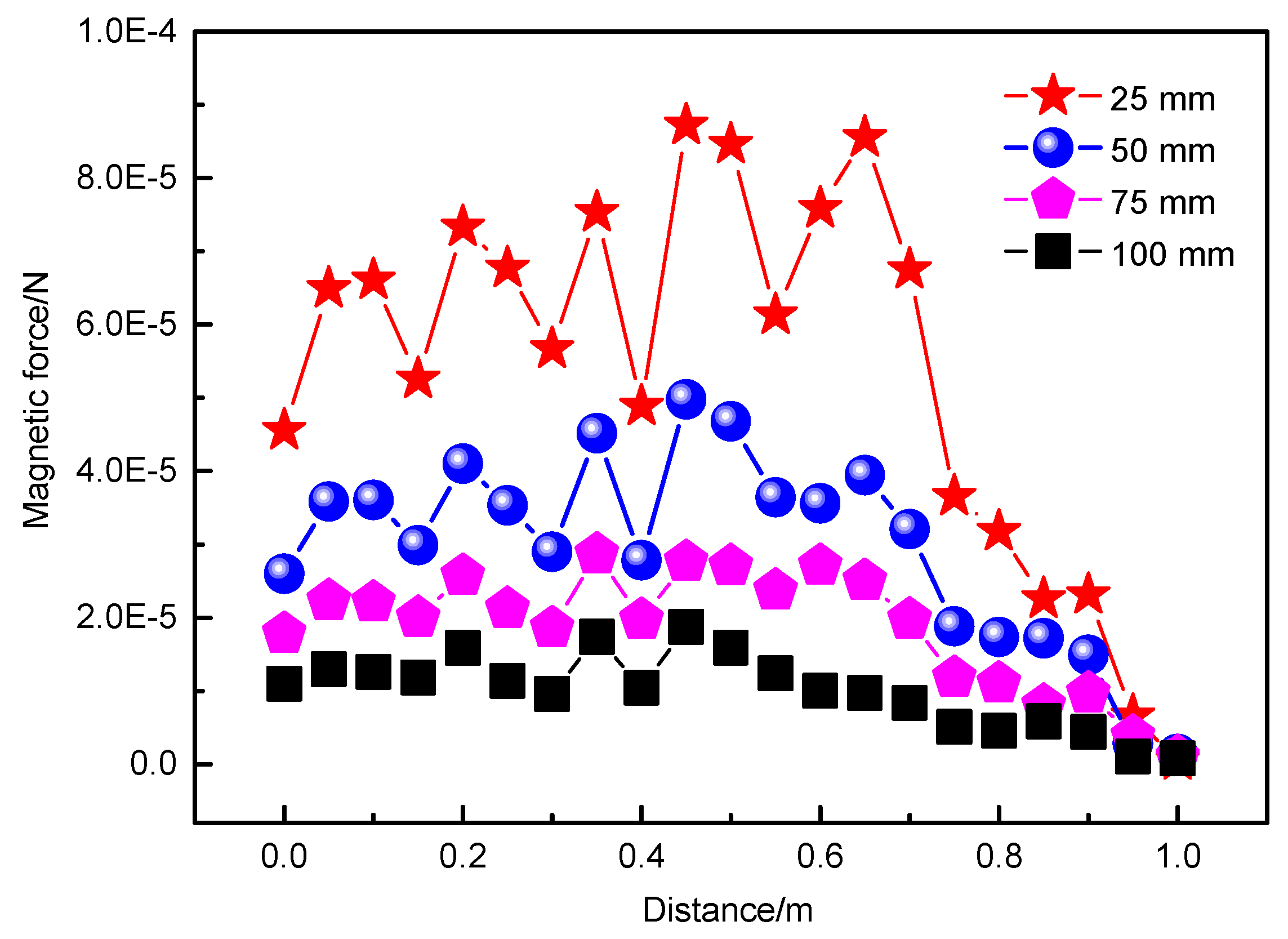
3.4. Effect of Distance on Electromagnetic Force
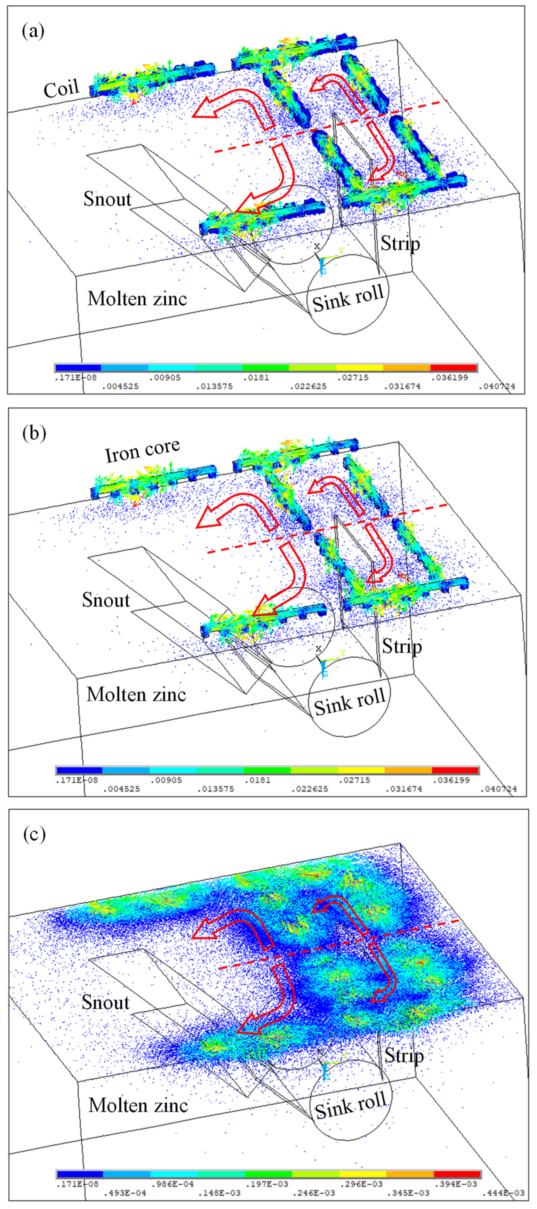
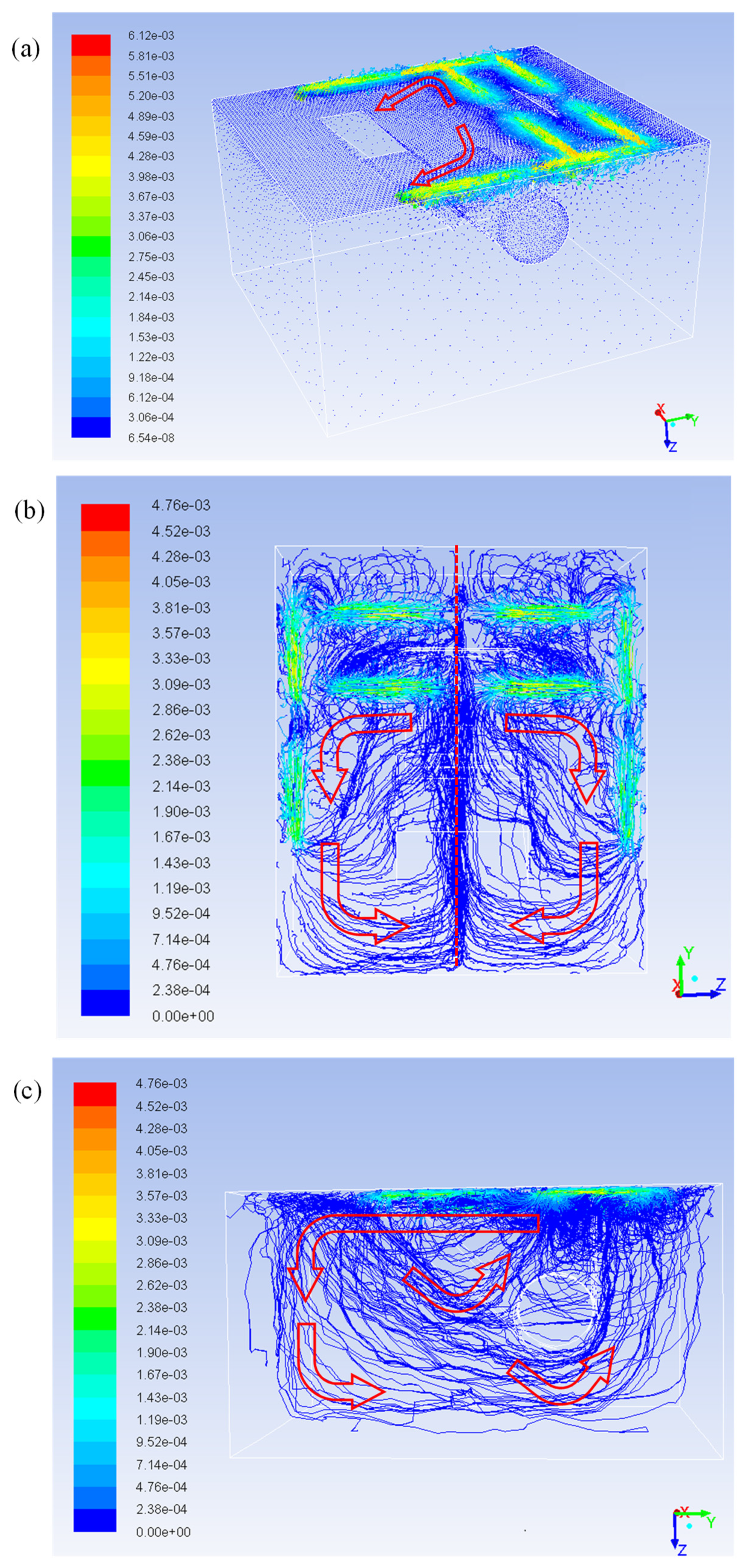
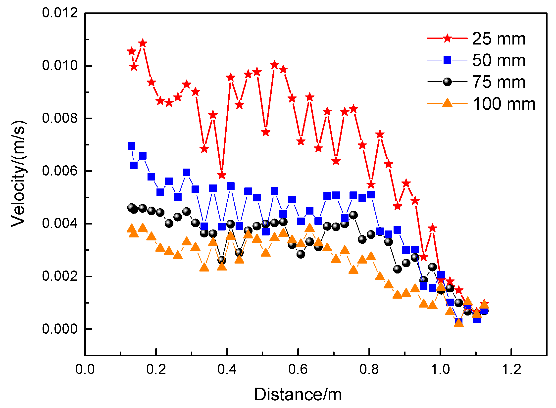
In theory, magnetic field motivated by the electromagnetic dross removal device should have an effective function distance [15]. The distance between the bottom surface of the iron core and the top surface of molten zinc was called the “Distance (D)” in here. The electromagnetic force with a current density of 300,000 A/m2 and a frequency of 30 Hz as well as different D was calculated and the result was shown in Figure 5. It directly reflected that magnetic force increased with the decrease of D. In fact, D can not be as small as possible, and there was an appropriate value range which was promised to apply in industrial production in avoid of the influence of the top surface fluctuation of molten zinc and the damage induced by the spatter of molten zinc. Taking the above mentioned aspects, it was better to choose D changing from 50 to 75 mm.

3.5. Flow Field

Figure 6a showed molten zinc flow vectors in the zinc pot when applying the electromagnetic dross removal technology. It clearly presented that molten zinc was accelerated under the influence of the electromagnetic dross removal device, and the flow direction was consistent with the functional direction of magnetic force. Figure 6b showed molten zinc flow vectors under the effect of the electromagnetic dross removal technology with the top view. Molten zinc flowed toward the zinc pot wall and then turned its direction to the perpendicular direction as shown in Figure 6b. The left and the right parts departed by the straight dotted line were nearly symmetric. The molten zinc flow vectors under the effect of the electromagnetic dross removal technology in the inner zinc pot depicted in Figure 6c. There were three kinds of flow condition for molten zinc. Firstly, most of molten zinc flowed on the top surface. In the second, some molten zinc flowed toward to sink roll driven by the steel strip movement and it ascended passing the sink roll. Otherwise, a few of molten zinc flowed along the zinc pot wall and finally flowed back to the top surface of molten zinc.
Based on the above results and taking D into account, the flow velocity of molten zinc at the selected position labeled in Figure 3a was calculated when the 300,000 A/m2 current density and 30 Hz frequency, and the result exhibited in Figure 7. It identified that flow velocity of molten zinc increased with the decrease of D, however, velocity discrepancy were prominent changing with the decrease of D at the same time. It illustrated that it reasonable for applying an appropriated D in range from 50 to 75 mm.
Additionally, in consideration of frequency, the flow velocity of molten zinc at the selected position labeled in Figure 3a was calculated under the circumstance of 300,000 A/m2 current density and 75 mm D, and the result exhibited in Figure 8. The flow velocity firstly increased and then decreased with the increase of frequency, and the maximum velocity can be obtained when the frequency was 30 Hz. In view of the calculated velocity result, it manifested that a high frequency was inappropriate.

4. Conclusions

In this work, a new electromagnetic dross removal technology applied in zinc pot of hot-dip galvanizing line was proposed. On account of industrial application condition and considering the influence of loading conditions, the numerical simulation calculation of the electromagnetic dross removal technology was carried out. The results indicated that a preferable dross removal result and a steady flow field can be obtained when the load current density, the frequency, and D were 300,000 A/m2, 30 to 100 Hz, and 50 to 75 mm, respectively. It should be noted that the electromagnetic dross removal technology was complex and the present work was insufficient. In the following work, the effects of the layout of electromagnetic field as well as the thermal field on the dross removal efficiency should be further investigated and discussed.

Author Contributions

Conceptualization, Q.G. and Y.X.; methodology, T.L.; software, M.C.; validation, Y.X.; formal analysis, K.Z.; investigation, Y.L. and D.P.; writing—original draft preparation, Y.X.; writing—review and editing, Q.W.; supervision, Y.X.; project administration, Q.G.; funding acquisition, Q.G. All authors have read and agreed to the published version of the manuscript.

Funding

This work is financially supported by the National Key Research and Development Program of China (Grant No. 2021YFB3702005).

Conflicts of Interest

The authors declare no conflict of interest.

References

  1. Hua, F.A.; Hou, S.; Li, J.P. Effect of liquid zinc chamfer on electromagnetic force in vertical electromagnetic sealing process. J. Northeast. Univ. 2018, 39, 808–812. [Google Scholar]
  2. Wang, Z.; Gao, J.T.; Shi, A.J.; Meng, L.; Guo, Z.C. Recovery of zinc from galvanizing dross by a method of super-gravity separation. J. Alloys Compd. 2018, 735, 1997–2006. [Google Scholar] [CrossRef]
  3. Kim, Y.H.; Cho, Y.W.; Chung, S.H.; Shim, J.D.; Ra, H.Y. Numerical analysis of fluid flow and heat transfer in molten zinc pot of continuous hot-dip galvanizing line. ISIJ Int. 2000, 40, 706–712. [Google Scholar] [CrossRef] [Green Version]
  4. Lee, S.J.; Kim, S.; Koh, M.S.; Choi, J.H. Flow field analysis inside a molten Zn pot of the continuous hot-dip galvanizing process. ISIJ Int. 2002, 42, 407–413. [Google Scholar] [CrossRef]
  5. Ilinca, F.; Hétu, J.F.; Ajersch, F. Three-dimensional numerical simulation of turbulent flow and heat transfer in a continuous galvanizing bath. Numer. Heat Transf. Part A 2003, 44, 463–482. [Google Scholar] [CrossRef]
  6. Ajersch, F.; Ilinca, F.; Hétu, J.F. Simulation of flow in a continuous galvanizing bath: Part II. Transient aluminum distribution resulting from ingot addition. Metall. Mater. Trans. B 2004, 35, 171–178. [Google Scholar] [CrossRef] [Green Version]
  7. Dash, S.K.; Dutta, M.; Rajesh, N. Use of flow barriers to eliminate vortex in the flow field generated in a continuous galvanizing bath. ISIJ Int. 2005, 45, 1059–1065. [Google Scholar] [CrossRef]
  8. Vieira, R.R.; Eleutério, H.L.; de Oliveira, T.G.; Bagatini, M.C.; Tavares, R.P. Numerical simulation of zinc flow in different layouts of galvanization pot. Mater. Res. 2021, 24, e20200477. [Google Scholar] [CrossRef]
  9. Liu, T.; Wang, Q.; Yuan, Y.; Wang, K.; Li, G.J. High-gradient magnetic field-controlled migration of solutes and particles and their effects on solidification microstructure: A review. Chin. Phys. B 2018, 27, 118103. [Google Scholar] [CrossRef]
  10. Liu, T.; Xiao, Y.B.; Lu, Z.Y.; Hirota, N.; Li, G.J.; Yuan, S.; Wang, Q. Wetting behaviors of molten melt drops on polycrystalline Al2O3 substrates in high magnetic fields. J. Mater. Sci. Technol. 2020, 41, 187–190. [Google Scholar] [CrossRef]
  11. He, Y.X.; Li, J.S.; Li, L.Y.; Wang, J.; Yildiz, E.; Beaugnon, E. Magnetic-field-induced chain-like assemblies of the primary phase during non-equilibrium solidification of a Co-B eutectic alloy: Experiments and modeling. J. Alloys Compd. 2020, 815, 152446. [Google Scholar] [CrossRef]
  12. Wang, L.; Hou, Y.D.; Shi, L.T.; Wu, Y.W.; Tian, W.X.; Song, D.K.; Qiu, S.Z.; Su, G.H. Experimental study and optimized design on electromagnetic pump for liquid sodium. Ann. Nucl. Energy 2019, 124, 426–440. [Google Scholar] [CrossRef]
  13. Chang, F.C.; Hull, J.R.; Beitelman, L. Simulation of flow control in the meniscus of a continuous casting mold with opposing alternating current magnetic fields. Metall. Mater. Trans. B 2004, 35, 1129–1137. [Google Scholar] [CrossRef]
  14. Zhu, X.W.; Li, D.W.; Wu, C.L.; Marukawa, K.; Wang, Q. Structural optimization of electromagnetic swirling flow in nozzle of slab continuous casting. Acta Metall. Sin. 2018, 31, 1317–1326. [Google Scholar] [CrossRef]
  15. Hou, S.; Hua, F.A. Research progress of electromagnetic enclosed slot technology in hot galvanizing. Surf. Technol. 2017, 46, 165–173. [Google Scholar]
Figure 1. Schematic diagram of numerical simulation geometry model for the electromagnetic dross removal technology.
Metals 12 01714 g001
Figure 2. Magnetic field distribution in: (a) the coils; (b) the iron cores; (c) the molten zinc.
Metals 12 01714 g002
Figure 3. (a) Schematic diagram of the selected position for calculating magnetic force; (b) The calculated magnetic force changing with current density.
Metals 12 01714 g003
Figure 4. The calculated magnetic force changing with frequency.
Metals 12 01714 g004
Figure 5. The calculated magnetic force changing with D.
Metals 12 01714 g005
Figure 6. Flow vectors of: (a) zinc pot; (b) molten zinc with the top view; (c) molten zinc with the end view.
Metals 12 01714 g006
Figure 7. Flow velocity of molten zinc changing with D.
Metals 12 01714 g007
Figure 8. Flow velocity of molten zinc changing with frequency.
Metals 12 01714 g008
Table 1. Electromagnetic dross removal device parameters and physical parameters of molten zinc.
ItemLength of Iron Core/mmWidth of Iron Core/mmRelative PermeabilityDensity/(kg/m3)Turbulent Viscosity/(Pa·s)Electrical Resistivity/(Ω·m)
Values126060167000.0043.7 × 10−7
Publisher’s Note: MDPI stays neutral with regard to jurisdictional claims in published maps and institutional affiliations.

