Article

Nonlinear Response of Tilting Pad Journal Bearings to Harmonic Excitation †

Department of Civil and Industrial Engineering, University of Pisa, Largo Lazzarino, 56122 Pisa, Italy
*
Authors to whom correspondence should be addressed.
This paper is an extended version of the paper published in Ciulli, E.; Forte, P. Nonlinear Effects in the Dynamic Characterization of Tilting Pad Journal Bearings. In the proceedings of the International Conference of IFToMM ITALY, Cassino, Italy, 29–30 November 2018.
Machines 2019, 7(2), 43; https://doi.org/10.3390/machines7020043
Submission received: 19 April 2019 / Revised: 25 May 2019 / Accepted: 14 June 2019 / Published: 17 June 2019
(This article belongs to the Special Issue Advances of Italian Machine Design)

Abstract

:
In the experimental identification of dynamic bearing coefficients, usually small perturbations around the static equilibrium position are assumed and linear coefficients are considered. In the literature, studies on non-linear effects in plain journal bearings, especially from a numerical point of view, are reported. Few similar studies can be found on tilting pad journal bearings (TPJB). The present work reports some peculiar aspects observed during the experimental identification procedure of TPJB linear dynamic coefficients. The tests are performed on a test bench designed for large size journal bearings operating at high peripheral speeds and static loads. A quasi-static procedure is developed to quickly check the results obtained from the usually adopted dynamic excitation. It consists of applying a slowly rotating force to the floating stator and measuring the relative displacement of the stator from the rotating shaft. Different levels of static and dynamic load are applied to two different TPJBs with four and five pads. Deformed orbits have been observed increasing the ratio between dynamic load and static load, suggesting the presence of non-linearity. Similar results are obtained with simple analytical models assuming suitably tuned non-linear stiffness terms.

1. Introduction

Tilting pad journal bearings (TPJB) are widely used in turbomachinery because of their stability characteristics at high speeds. For design purposes it is essential to know the coefficients that characterize their dynamic behavior. These coefficients are usually obtained with the assumption of small amplitude motions with respect to the static equilibrium position, which allows linearization according to the well-known Lund model [1] and many different experimental procedures have been proposed to identify them [2,3].
For plain journal bearings, Qiu [4] has experimentally verified that the error in the estimation of dynamic coefficients not considering nonlinearity is negligible when the perturbation displacement amplitude is in the order of magnitude of 0.02 of radial clearance (c) and suggests displacement amplitudes not exceeding 0.05c to contain the error within 2.5%.
However, in industrial practice, the amplitude of the shaft vibrating motion can reach about 0.1c in operating conditions, violating the hypothesis of small perturbations. Moreover, in experimental tests for the identification of linearized dynamic coefficients, the choice of imposing small perturbations conflicts with the need for measuring small displacements with reduced errors.
From an analytical/numerical point of view, several authors have tackled the problem of nonlinearity, especially in plain journal bearings. The approach consists of the direct integration of the Reynolds equation [5] and the description of the oil-film forces with a larger number of dynamic coefficients with respect to the classical linearized eight ones, by retaining more terms of the Taylor series expansion [6,7]. The proposed nonlinear models proved to represent well the nonlinear effects within the considered journal bearings. A parametric analysis to study the sensitivity of non-linear forces in journal bearings of different types is reported in Reference [8]. Results are presented for a two-lobe elliptical bearing showing the effects of several parameters on size, shape, and orientation of the elliptical orbits produced by synchronous vibrations.
As far as the TPJB is concerned, the literature offers less contributions compared to plain journal bearings. From the analytical/numerical point of view, nonlinear effects were studied by direct integration of the Reynolds equation in References [9,10,11,12,13,14], showing how the rotor orbit increasingly deviates from the theoretical elliptical orbit of the linear case as the ratio of dynamic and static load amplitudes increases. The effect of different unbalanced loads on a four-pad TPJB in the load-between-pad (LBP) configuration was investigated considering thermal and deformation effects in Reference [9]. Slightly triangular journal orbits were found with a dynamic load about 70% of the static one while nearly quadrilateral orbits were found with a dynamic load greater than the static one. The position and the shape of the orbits appeared to be influenced by thermal effects on both viscosity and pad deformations, while the influence of the elastic deformations appeared to be smaller. Thermo-elasto-hydrodynamic theory should be used to predict more accurate results as shown also in Reference [10]. The effect of the liner compliance on the nonlinear dynamic behavior of the same TPJB used in References [9,10] supporting vertical and horizontal rotors was investigated in Reference [11]. Almost square orbits were found when the unbalanced load was applied to the vertical rotor (with zero static load) whilst three-lobed orbits were found with a dynamic load 50% of the static one applied to the horizontal rotor. Particularly for the horizontal configuration, shape and size of the orbits are influenced by several factors such as liner thickness and material, preload, pivot offset, and radial clearance. Three-lobed orbits were also found for a TPJB with two loaded pads in LBP configuration [12,13] and five-lobed orbits for a five-pad bearing [14] also with an approximated analytical solution using Fourier series developments. Other researchers have proposed models with an increased number of coefficients identifying them from the dynamic response obtained by direct integration [15].
From the experimental point of view different TPJBs were tested in Reference [16] with two different test rigs detecting typical non-linear behaviors. Symptoms of a non-linear behavior of the pad journal bearings of two industrial machines were found in Reference [17]. The dynamic coefficients of three nonlinear models were identified with a different number of coefficients (28, 24, 36) on a five-pad TPJB bearing, with a 100 mm diameter [18]. The results of the three nonlinear models and the linear one are in good agreement regarding the identified linear terms. Moreover, the identified stiffness and damping coefficients appear to decrease with increasing dynamic force amplitude with a reduction of up to 60% for direct stiffness in the case of a dynamic force increase from 5% to 30% of the static load.
Following a preliminary investigation on possible nonlinear effects in a large size TPJB [19], the present paper focuses on the nonlinear response of tilting pad journal bearings to harmonic excitation observed during the experimental procedure for the identification of the linear dynamic coefficients. In particular it uses the tests to ascertain the linear and nonlinear range of displacements prior to the dynamic characterization campaign. Nonlinear effects related to the dynamic/static load ratio should in fact be considered in the experimental identification procedure and accounted for or avoided. There are very few experimental results published on this topic and in particular on large size TPJB. De Falco et al. [16] and Chatterton et al. [18] have dealt with the problem with smaller bearings and different test rig configurations. Moreover, as far as the authors are aware, the application of an asynchronous rotating force instead of harmonic forces with constant directions, with different dynamic/static load ratios, is new. The tests are performed on a unique experimental apparatus realized for large size journal bearings operating at high peripheral speeds and static loads, with single tone or multi-tone dynamic loads. The design criteria are described in Reference [20]. The main characteristics of the realized bench and the first experimental results obtained during the commissioning with a four-pad TPJB are reported in [21,22]. Results obtained under stationary and slow variable conditions are particularly reported in Reference [21]. The different systems related to the test rig are shown in more detail in Reference [22] together with the procedures adopted for both static and dynamic tests.

2. Materials and Methods

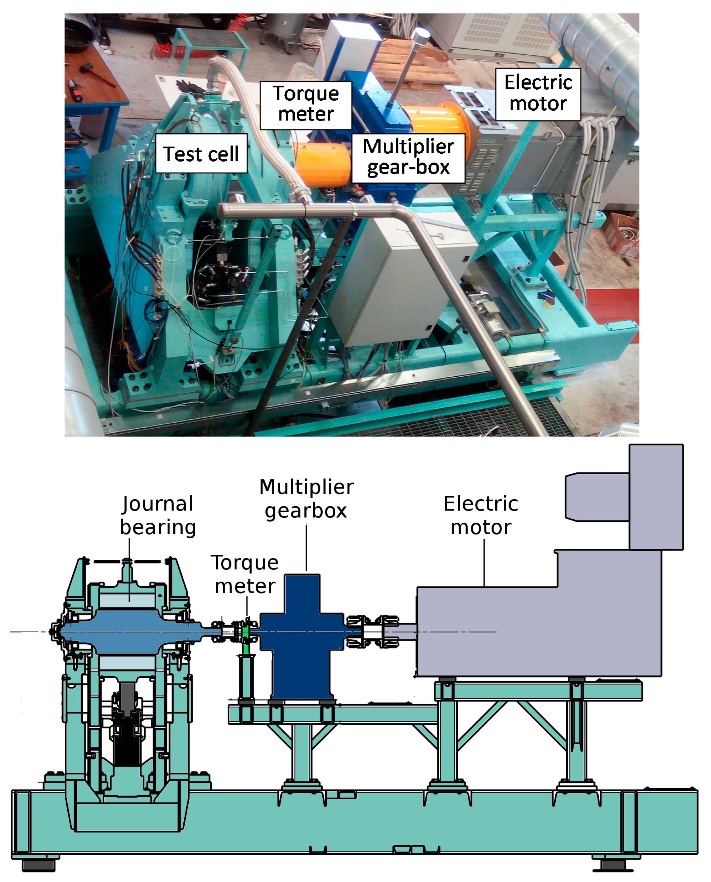
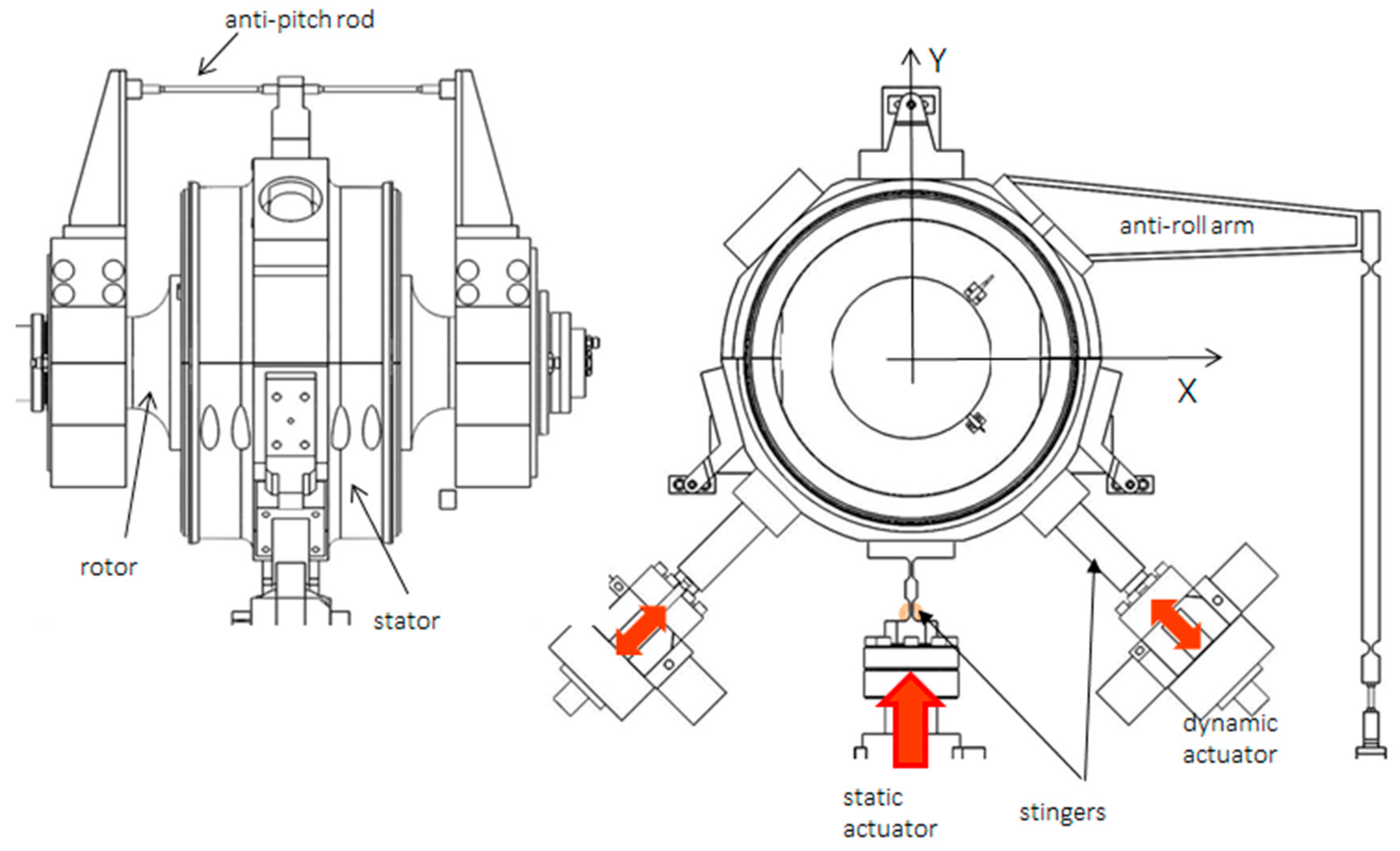
Figure 1 shows a picture and a schematic drawing of the test bench. The rotor, supported by rolling bearings, is driven by an electric motor connected to a gearbox with a gear ratio of six. A torque meter measures the driving torque. The test bearing housing is floating, and the static load and the dynamic ones are applied to it by three hydraulic actuators. The static load acts upwards in the vertical direction while the dynamic loads are applied in mutual orthogonal directions, at 45° with respect to the vertical one (Figure 2). The dynamic actuators can work one at a time or simultaneously. In the second case, if they operate with equal amplitude in phase, they can produce a vertical force (y direction), in antiphase a horizontal force (x direction), and in quadrature a rotating force. Three pitch stabilizers, placed at 120° around the bearing, provide the bearing housing with axial constraints that can be adjusted to align the bearing with respect to the rotor. Table 1 summarizes the main characteristics of the test rig.
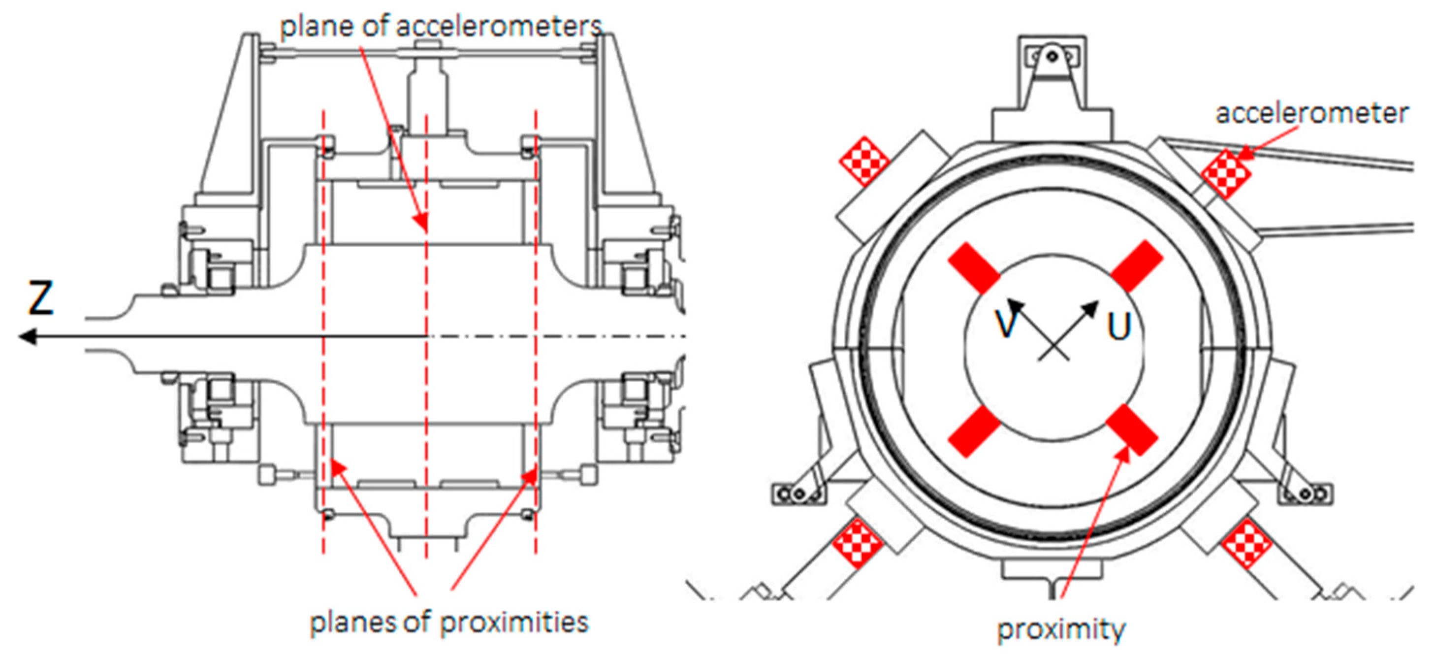
Load cells and instrumented stingers, capable of measuring dynamic loads, measure all significant forces acting on the bearing housing while high-resolution proximity sensors measure the relative displacements of the bearing housing and the rotor in the directions of the dynamic actuators shown in Figure 2 (U and V directions shown in Figure 3). Eight sensors are employed, placed on two parallel planes perpendicular to the bearing axis. Four accelerometers measure the acceleration of the stator at the mid-section in the direction of the dynamic actuators.
Three different oil supply systems are used for the TPJB, the actuators, and the multiplication gearbox.
Tests are managed by a very complex control and data acquisition system. Up to 30 high-frequency signals (forces and torque, displacements, rotational speed, accelerations) can be acquired and sampled at up to 100 kHz, while up to 60 low-frequency (quasi-static) signals (temperatures, pressures, and flow-rates in the main and auxiliary lubrication systems and motor electric current) can be acquired and sampled at 1 Hz. A high sampling rate means an accurate description of signals but also a large amount of stored data; however, since the identification tests are rather short, data storage is not a problem. High-frequency signals are also averaged every second and their mean values are stored together with the low-frequency ones.
The test articles consisted of a four-pad (without offset) and a five-pad (with offset) TPJBs provided by an industrial partner. The bearings had a 280 mm inner diameter and were tested in the load between pads configuration. No additional data will be given about the bearings and their characteristics due to a non-disclosure agreement with the company.
Two main types of test are usually carried out with the test apparatus:
  • The bump test to identify the bearing clearance, center, and alignment
  • The dynamic identification test to identify bearing stiffness and damping coefficients.
In the first test a rotating force vector applied to the bearing housing is generated by sinusoidal signals with 90° phase difference. The oil is not supplied, and the shaft is not rotating. The force must be increased until the polygon shaped orbit does not change.
In the second test the forces applied during excitation can contain one (“single tone” test) or more (“multitone” test) frequency components. As dynamic coefficients can vary with frequency, excitation tones are chosen below and above the rotational frequency avoiding harmonics and test bench resonances. The required synchronous values are then obtained by interpolation to avoid imbalance disturbance. Multitone tests with n frequency components have been proven to provide the same results of n single tone tests but in the time of a single test. For the identification of the dynamic linear coefficients, two tests with linearly independent excitations are required for each excitation frequency. The two tests consist in two distinct excitations, vertical (subscript y) and horizontal (subscript x), respectively, obtained using the dynamic actuators in in-phase (subscript f) and anti-phase (subscript a) operation modes. The bearing impedance matrix H, expressed in terms of stiffness (k) and damping (c) coefficients:
[ H x x H x y H y x H y y ] = [ k x x k x y k y x k y y ] + i ω [ c x x c x y c y x c y y ]
where ω is the excitation frequency, is determined in the frequency domain, using the Fast Fourier Transform (FFT), by multiplying the [2 × 2] bearing force complex matrix by the corresponding inverse displacement complex matrix:
[ H x x H x y H y x H y y ] = [ F b x f F b x a F b y f F b y a ] [ D x f D x a D y f D y a ] 1
where Fb indicates the amplitude of the force transform and D indicates the amplitude of the displacement transform. Synchronous coefficients are obtained at the shaft rotational frequency. The stiffness dynamic coefficients have shown to be practically independent of frequency for a wide range starting from quasi-static conditions. They are the basis of the simplified models that will be presented in Section 3.2.
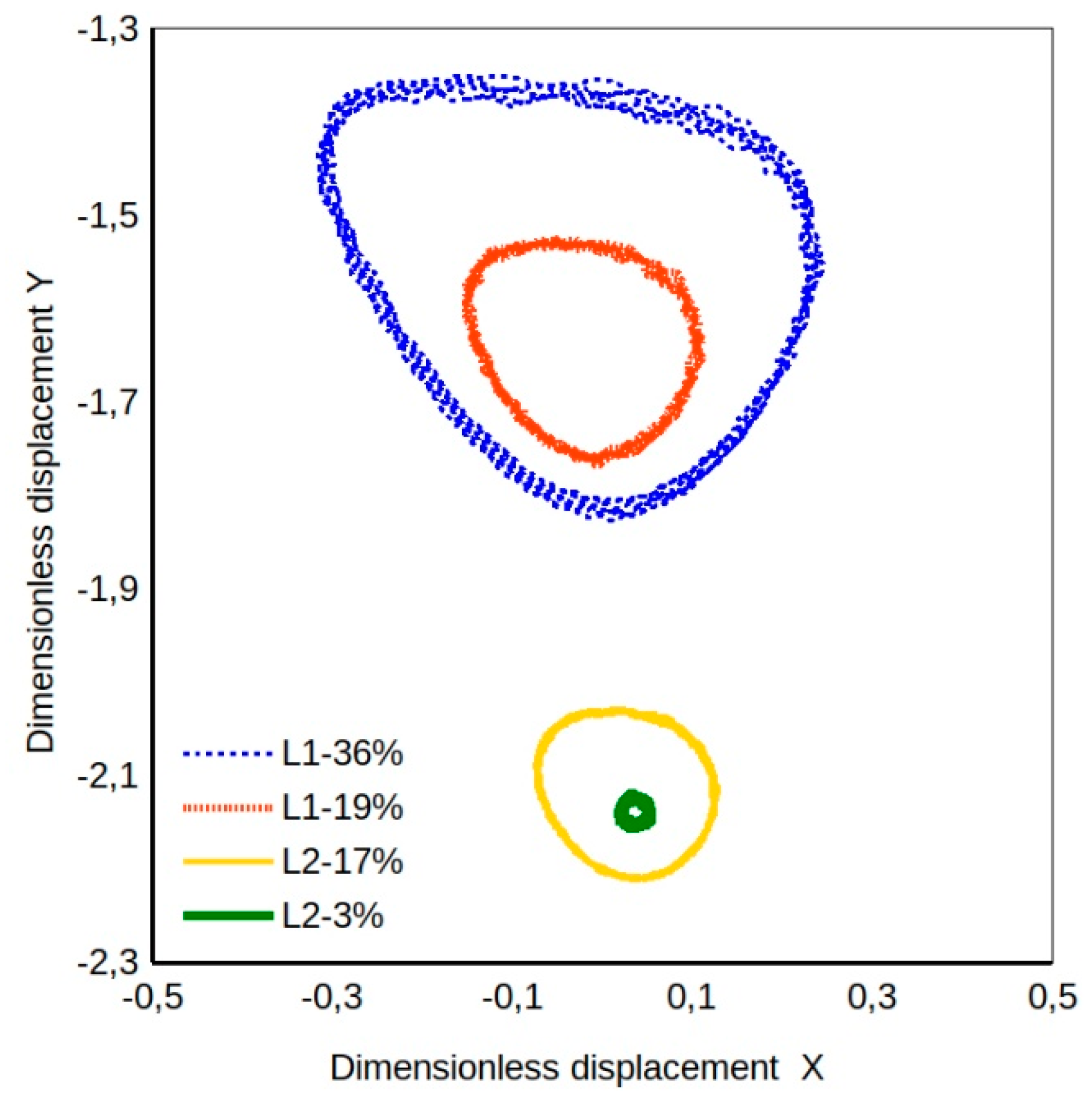
In addition to such tests, in order to ascertain the linear and nonlinear range of displacements prior to the dynamic characterization campaign, and also to have a reference stiffness estimate, another procedure has been developed. The stator is subjected to a slowly rotating force vector generated by equal amplitude sinusoidal forces with a 90° phase angle difference, applied by the two dynamic actuators. The force low rotational speed allows to consider the damping coefficients negligible. This work focuses on this latter test procedure that makes it possible to evidence nonlinear effects by detecting the loss of the typical elliptical orbit related to linear bearing film stiffness. In the tests reported in this work the shaft rotational speed was set at 1000 rpm while the frequency of the rotating load was set at 1 round every 100 s (i.e., 0.01Hz). Different static load levels were applied in load-between-pad configuration combined with different dynamic load levels ranging 3% to 36% of the static load. Forces and displacements were recorded at a rate of one sample/s.

3. Results

3.1. Experimental Results

Figure 4 shows the plots of the applied horizontal and vertical dynamic load, obtained in four different tests for the four-pad TPJB for two levels of static load, with the higher (L2) about double the lower one (L1).
The dynamic load plot is circular because it is a rotating vector with a constant amplitude controlled by means of the dynamic actuators with the feedback of the load sensor system. The dynamic load is indicated in the label as percentage of the static load. About five rotating load cycles are shown for each test. The corresponding stator orbits are shown in Figure 5. The zero values correspond to the central position of the bearing. The displacement fluctuation, related to the centrifugal force due to the shaft rotation, is noticeable particularly for the low static load conditions. It is evident that the orbit position is related to the static load level while its shape is greatly influenced by the dynamic/static load ratio, becoming more elliptical and closer to the linear orbits (Figure 5 case L2-3%) as the ratio decreases. The shapes are similar to the ones theoretically found by direct integration of the Reynolds equation in References [9,11,12] for four-pad TPJBs.

3.2. Simple Analytical Models

In order to give a possible explanation for the obtained orbits, the influence of different factors was evaluated by simulation with simple bearing models represented by linear and quadratic dynamic coefficients.
Analytical models with increasing complexity were devised assuming hydrodynamic forces having the following non-linear relations with displacements, obtained by adding quadratic terms to the commonly used linear relations, neglecting damping due to the low excitation frequency of the rotating load:
f x = k x x d x + k x y d y + k x x 2 d x 2 + k x y 2 d y 2 ,
f y = k y x d x + k y y d y + k y x 2 d x 2 + k y y 2 d y 2
The main objective of this work was not the identification of nonlinear coefficients but to preliminarily investigate the possibility of replicating the experimental nonlinear orbits with simple nonlinear models. Thus, the linear coefficients of Equations (3) and (4) were set equal to those obtained by the identification tests described in the previous section while the quadratic coefficients were determined by a trial and error procedure to get a good fit of the experimental orbits with analytical ones based on the proposed models.
The simplest analytical linear model takes into account only the direct stiffness coefficients in the linear relation with displacements:
d x = f x k x x ,   d y = f y k y y .
The linear stiffness model takes into account both direct and cross-coupled stiffness coefficients in the linear relation with displacements:
d x = k y y f x k x y f y k x x k y y k x y k y x ,   d y = k x x f y k y x f x k x x k y y k x y k y x .
The simplest nonlinear model takes into account only direct linear and quadratic stiffness coefficients:
d x = k x x + k x x 2 + 4 k x x 2 f x 2 k x x 2 ,   d y = k y y + k y y 2 + 4 k y y 2 f y 2 k y y 2
A second non-linear model takes into account linear direct and cross-coupled stiffness coefficients and quadratic direct stiffness coefficients. First of all, the force and displacement components of Equations (1) and (2) were expressed in polar coordinates:
f x = F cos ( θ + φ ) ,   f y = F sin ( θ + φ ) ,
d x = R cos ( θ ) ,   d y = R sin ( θ ) .
After squaring the terms of both Equations (3) and (4), they were summed obtaining an equation of the fourth degree of R that can be solved analytically as a function of θ:
R 4 ( k x x 2 2 c o s 4 ( θ ) + k y y 2 2 s i n 4 ( θ ) ) + R 3 [ 2 k x x 2 c o s 2 ( θ ) ( k x x c o s ( θ ) + k x y s i n ( θ ) ) + 2 k y y 2 s i n 2 ( θ ) ( k y x c o s ( θ ) + k y y s i n ( θ ) ) ] + R 2 [ ( k x x c o s ( θ ) + k x y s i n ( θ ) ) 2 + ( k y x c o s ( θ ) + k y y s i n ( θ ) ) 2 ] F 2 = 0 .
A rotating load was imposed as a sum of two sinusoidal functions with the same amplitude and a 90° phase shift, and the corresponding displacements were calculated. The case L1-36% (low static load, high load ratio) was chosen as reference case due to its extreme dynamic load conditions. For the sake of comparison, the same experimentally identified stiffness coefficients for the four-pad TPJB were used in all the analytical models while, for the quadratic coefficients, values tuned to fit the experimental orbits were adopted for the x and y directions for all nonlinear models. The value zero in the diagrams corresponds to the static equilibrium position. Further non-linear models were obtained by considering the dependence of stiffness coefficients from the actual vertical load, sum of the static load, and the vertical component of the rotating load, according to a fit of experimental results obtained for different static vertical loads and small dynamic ones. In such a case, a phase angle of a few degrees between the displacement vector and the force vector was included, affecting the model related to Equation (10). The orbits obtained with the different analytical models are presented in Figure 6, with dashed blue lines representing those of the constant stiffness models and red lines representing those of the load dependent stiffness models.
Comparing the orbits of Figure 6, one can observe that if only direct stiffness coefficients are included the orbits are necessarily circular due to the same bearing stiffness along the orthogonal directions. The inclusion of the linear cross-coupled stiffness coefficients in the model modifies the orbit shape in a tilted slightly elliptical one. Including second order direct stiffness coefficients in the model yields an orbit with a shape more similar to the experimental one with three lobes. It seems that including cross-coupled stiffness coefficients in this latter model makes it more adaptable but does not bring significant improvements unless a specific optimization procedure is performed. The inclusion of coefficient load dependence produces a vertical shift of all the orbits, an increase of the ellipticity for the simpler models, and more pronounced lobes for the nonlinear ones.

3.3. Comparison of Analytical and Experimental Results

In order to evaluate the capability of analytical models to simulate the actual bearing behavior, experimental loads and corresponding linear stiffness coefficients were implemented in the models, tuning the quadratic coefficients, to obtain orbits to be compared with the experimental ones. Figure 7 shows a comparison of orbits calculated with different load dependent stiffness models and experimental ones for three different load ratios.
The more complex nonlinear model is omitted at this point because its optimization deserves a further in-depth analysis and thus it is left to future development. It is evident especially at high load ratios that the nonlinear model overcomes the limitations of the linear ones and succeeds in replicating the experimental orbit shape. At lower load ratios the differences are less marked as the orbits tend to a more elliptical shape.
For very low load ratios, that is for reduced values of the dynamic force the orbit tends to become more circular and all models, linear and nonlinear, give similar results, as shown in Figure 7c for the case L2-3%, thus indicating a linear behavior. Note that in this case, since both displacement and force experimental values are very small, the measurement relative error increases and it is also quite difficult to control the rotating force vector at such load ratios. Those are the main reasons for the discrepancy of experimental and analytical orbits shown in Figure 7c.

4. Discussion

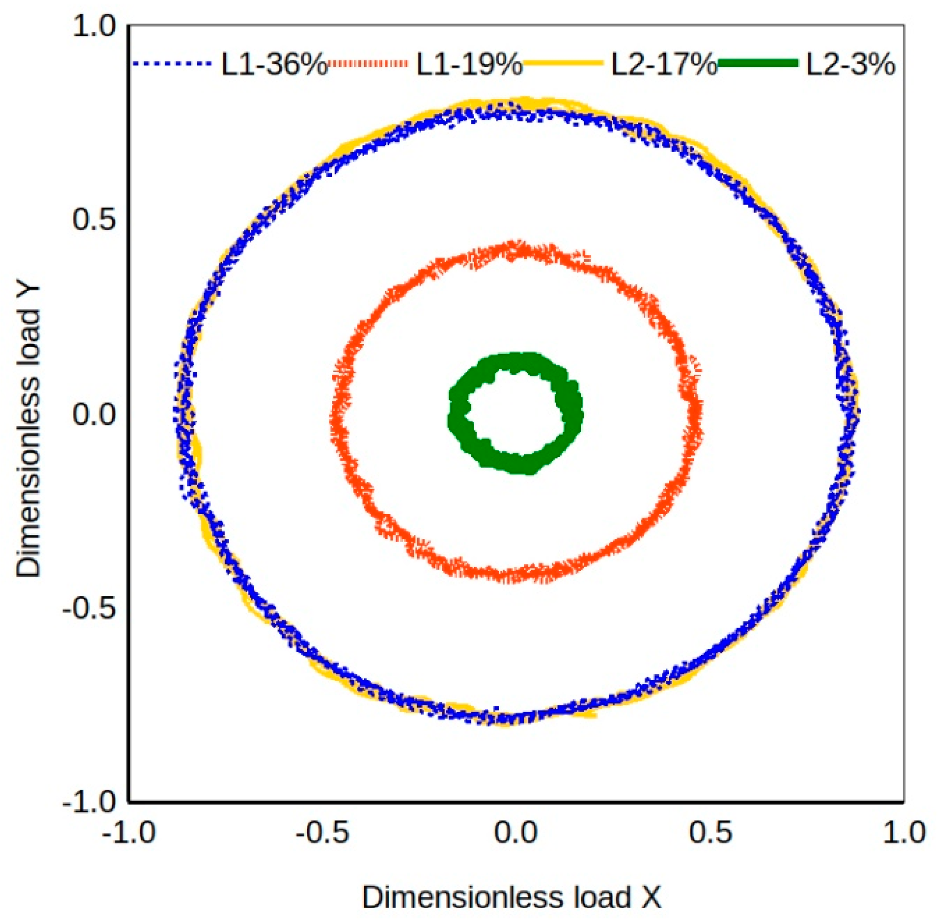
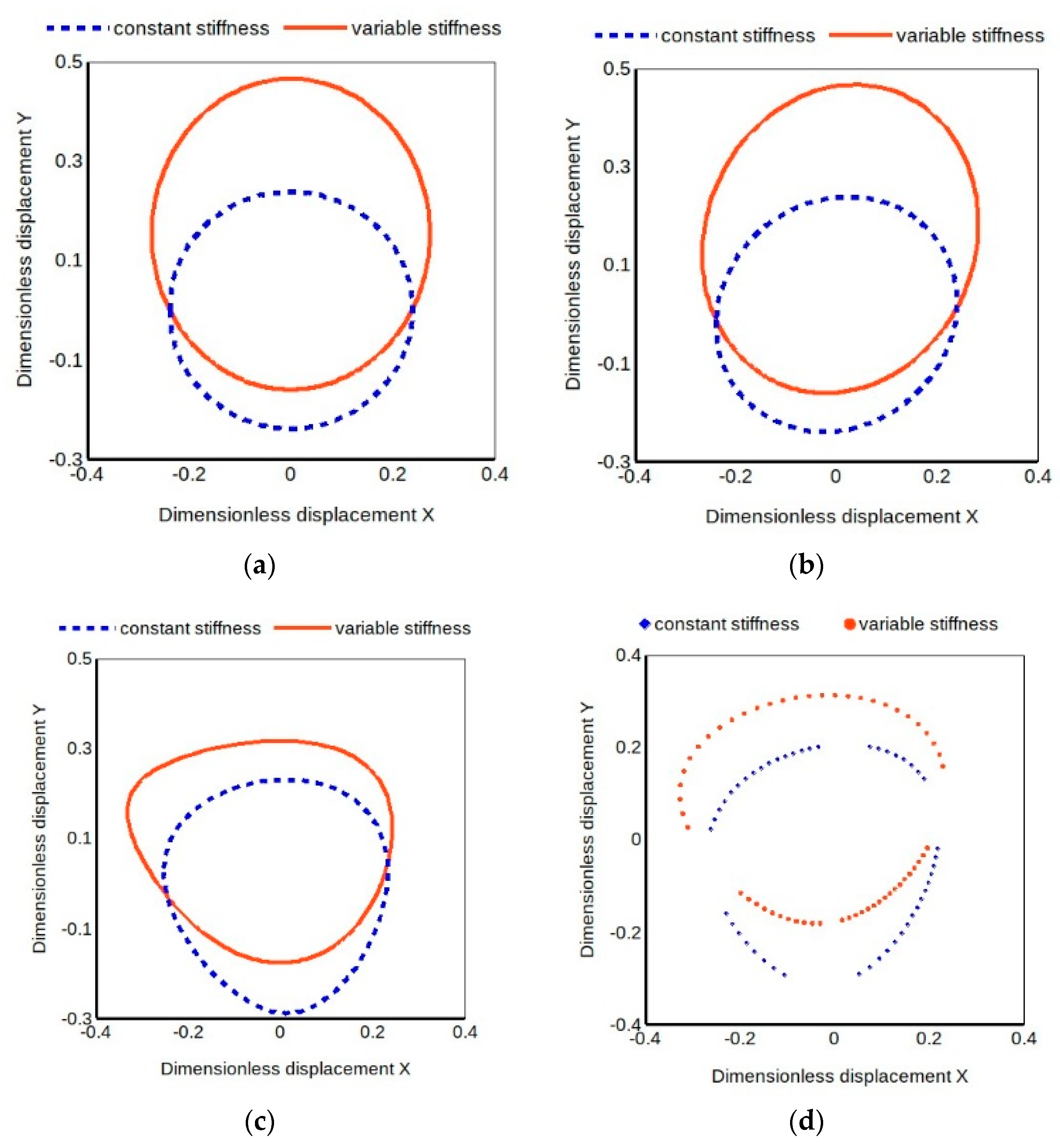
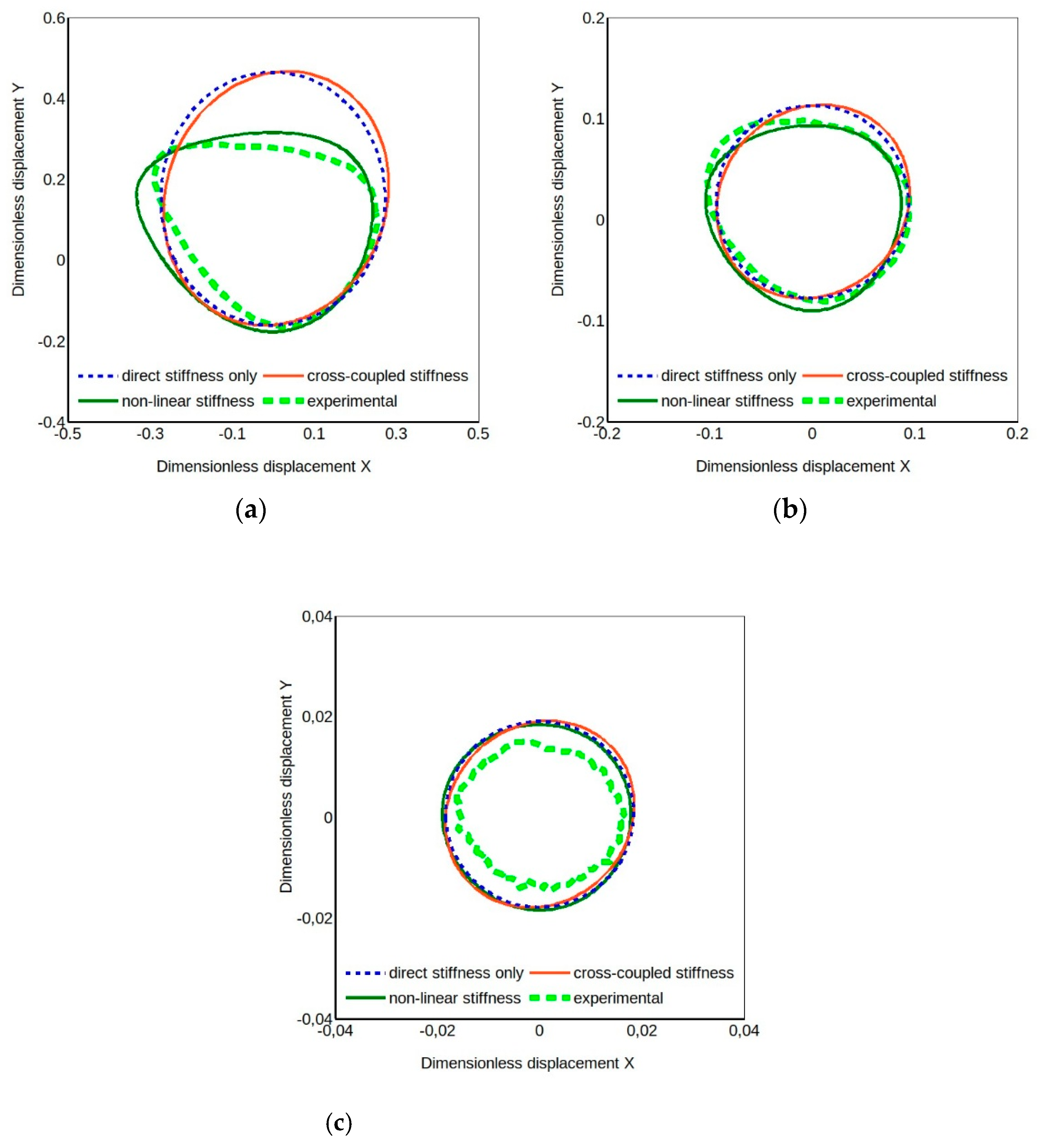
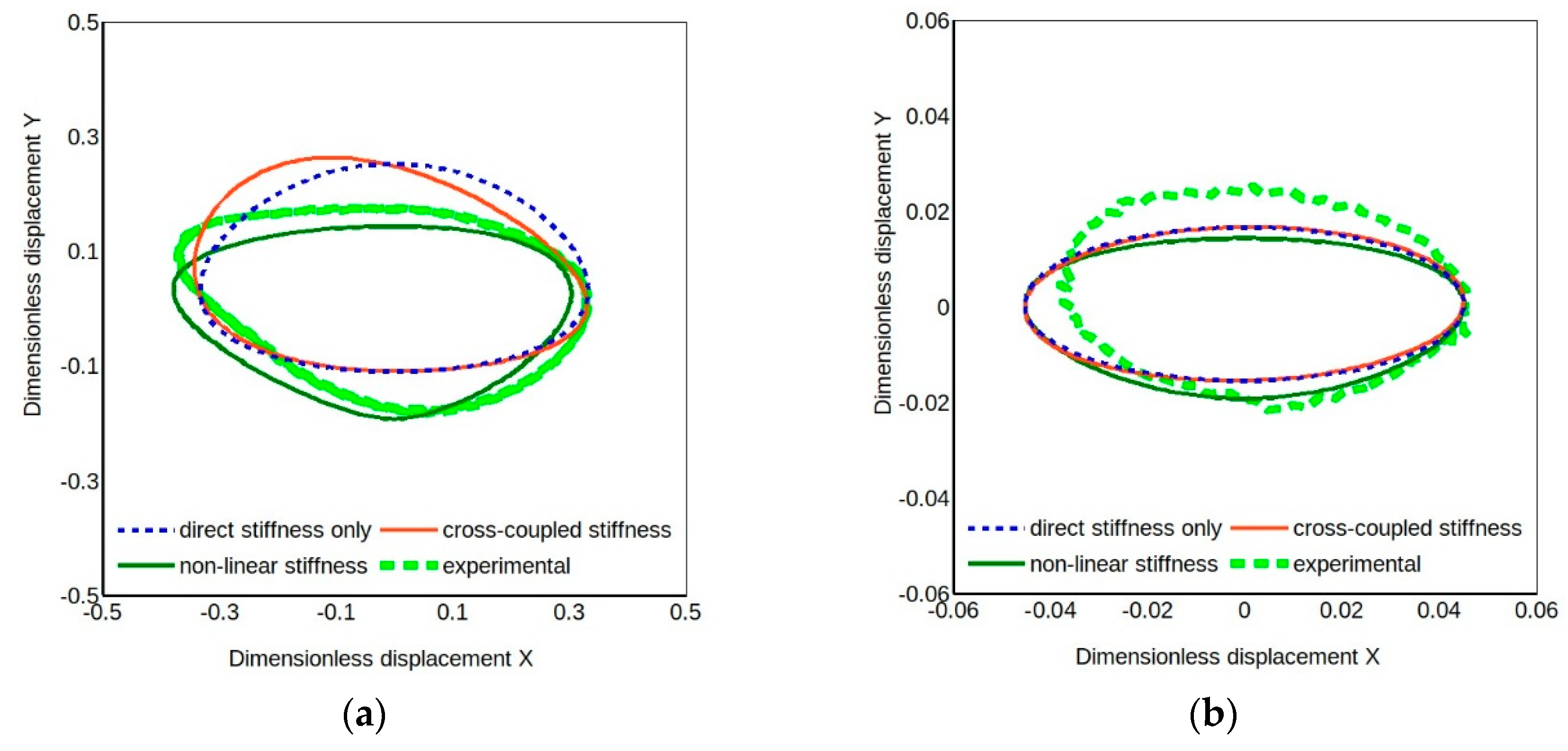
The results obtained for the four-pad TPJB that has equal direct stiffness coefficients and equal cross-coupled ones indicate that only models including second order direct stiffness coefficients can replicate the characteristic shape of the experimental orbit.
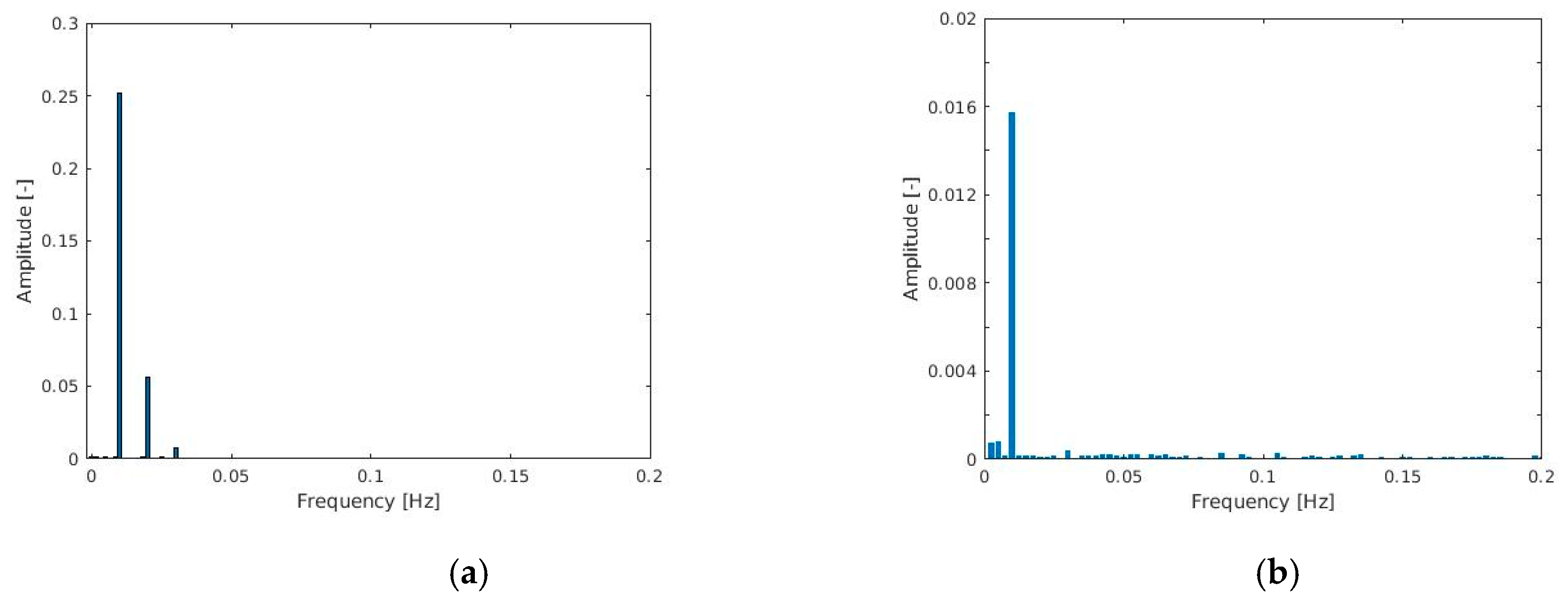
The non-elliptical shape of the orbits is reflected in the appearance of multiple frequency peaks in the Fast Fourier Transform (FFT) of the displacement signal as shown in Figure 8a (case L1-36%). As the excitation is a single tone force, the FFT content of the displacement with multiple frequencies indicates non-linear or coupled phenomena. Figure 8b shows the results of the same analysis performed for the L2-3% case whose orbit is surely more elliptical (Figure 7c). Note that the shaft rotational frequency (16.67 Hz) is not present in these diagrams focused on the low frequency zone. 
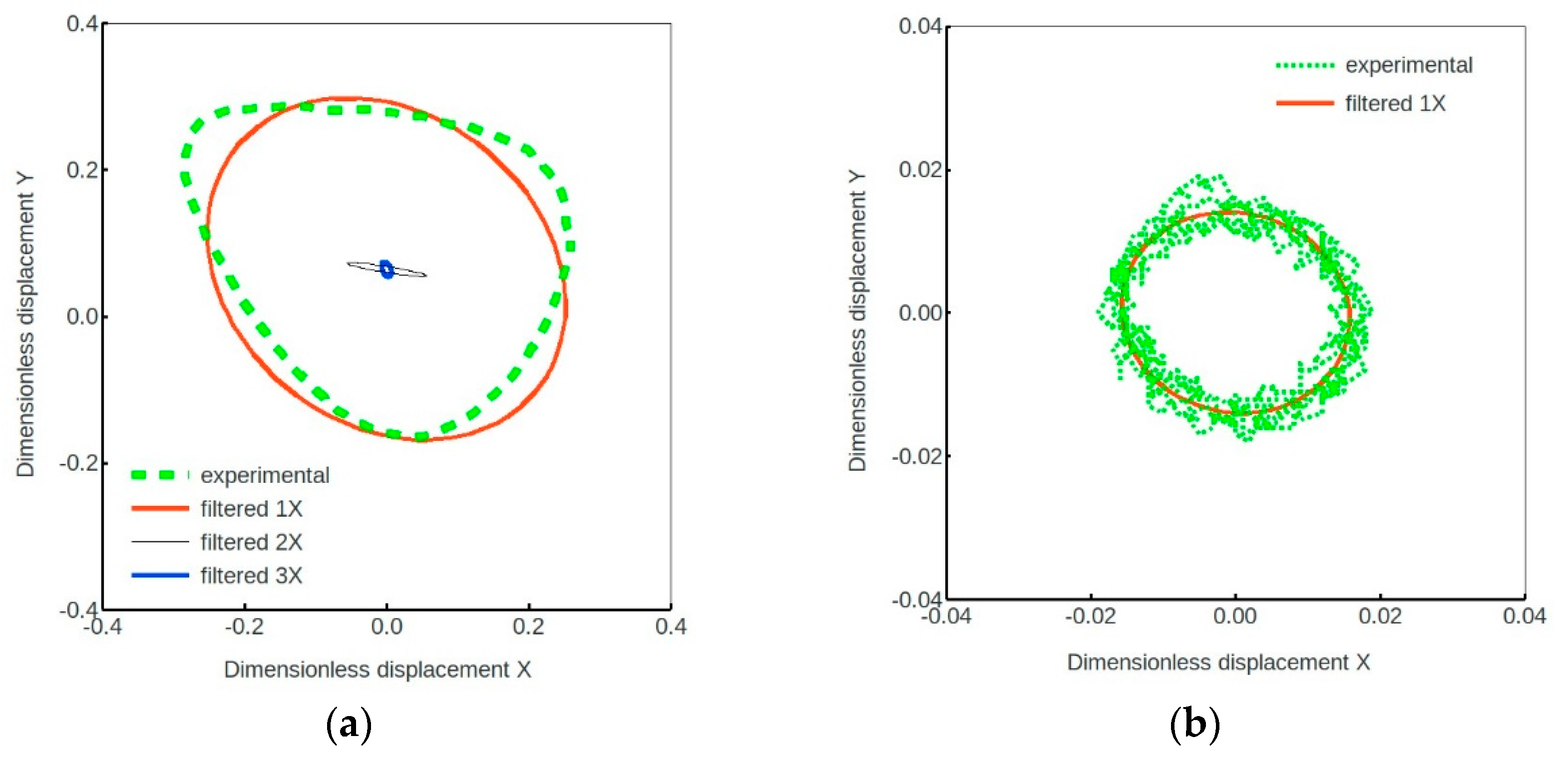
Figure 9 shows the experimental orbit of the case L1-36% compared with the orbits obtained filtering the results at the force rotational frequency (1X) and twice (2X) and three times (3X) the fundamental frequency. While the 1X harmonic component of displacement corresponds indeed to the linear orbit for low load ratios (case L2-3%, Figure 7c), the 1X filtered ellipse observed for a higher load ratio (case L1-36%) in Figure 9 appears with a tilt that is not justified with a linear model considering the negligible linear damping and cross-coupled stiffness coefficients, thus indicating the apparent effects of nonlinearity. Note that all data recorded during the rotation of the force vector are plotted in Figure 9b (four cycles in this case) instead of the averaged values as in Figure 7. This provides better evidence of the signal fluctuations due the difficulties in controlling and measuring low values of forces and displacements as mentioned above.
At the end of the tests some geometrical differences among the pads were also found. It is worth mentioning that geometrical errors can also influence the results, as reported for example in Reference [18].
In order to confirm the previous findings, the case of another TPJB was analyzed. It was quite different from the previous one as it had five offset pads of the same size. It underwent the same tests of the four-pad TPJB in the LBP configuration. Unlike the four-pad TPJB this bearing has quite different direct stiffness coefficients in the x and y directions (kyy greater than kxx), and that has obviously a remarkable impact on the orbit shapes. 
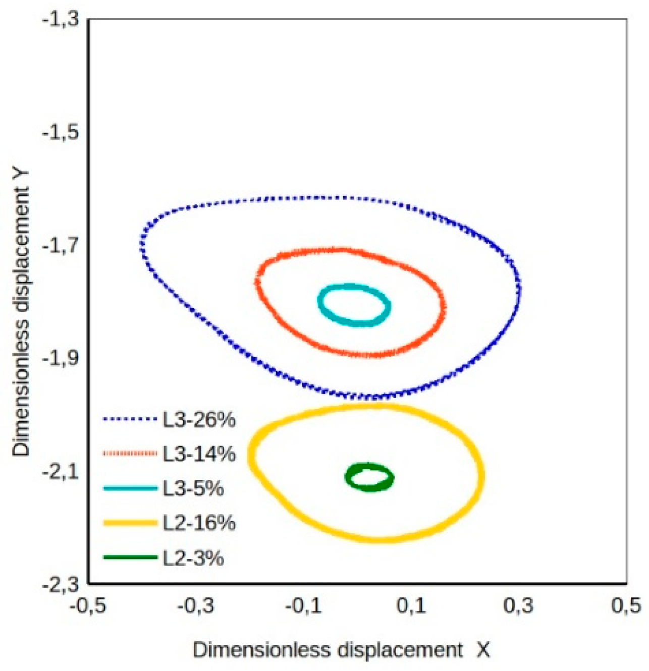
Figure 10 presents some experimental orbits for the five-pad TPJB for different load ratios and two different static load levels. The load L3 is about 60% of L2, so a little greater than the load L1 used for the four-pad TPJB. Figure 11 presents calculated and experimental orbits for three different models with load dependent direct stiffness coefficients. The difference in direct stiffness coefficients produces the ellipticity even of the orbits of the simpler models but the coefficient load dependence causes a distortion of the ellipse, though there is still a difference in its orientation compared to the experimental one. Again, when the load ratio is small, as in cases L3-5% and L2-3% of Figure 10, the orbit is elliptical and, as shown in Figure 11b, quite close to the classical linear model predicted one. Moreover, the model with quadratic coefficients produces an orbit more similar to the experimental one, particularly noticeable for larger load ratios. Nonetheless there is still margin for an optimized tuning of the estimated quadratic coefficients. Better results can be expected from a best fit optimization involving all dynamic coefficients, including the linear ones. The set of linear coefficients obtained by linear identification could be the starting solution of the nonlinear identification procedure that will be the object of future work.
The peculiar three lobe orbit shape, predicted by simulations [9,11,12] for horizontal rotors and found experimentally in the present work, has been ascribed to the number of pads involved in the bearing reaction to the load. With four pads, with a high static load between pads and a rotating load not overcoming the static one, the bearing behavior is similar to that with only two pads, like the one described in Reference [12]. The same behavior occurs with five pads with load between the pads, as can be deduced observing the results reported in this section. 3X components in the journal orbit, in addition to 1X and 2X, have been also reported in Reference [18] for a five-pad TPJB on a floating shaft configuration test rig. Unfortunately, comparison can be only qualitative because experimental conditions are quite different.

5. Conclusions

This paper presented new experimental results on the nonlinear response of large size TPJBs related to the dynamic/static load ratio, showing that nonlinear effects, usually neglected in conventional experimental identification procedures of the bearing dynamic coefficients, should be considered. A quasi-static procedure devised for a preliminary estimate of the bearing stiffness and of the linear displacement range was used to investigate, in a novel way, the nonlinear response of TPJBs. It consists of applying a slowly rotating force to the floating stator. Orbits with particular shapes, different from elliptical, were observed for increasing dynamic to static load ratio.
Numerical simulation using simple bearing models and assuming quadratic stiffness terms and coefficient load dependence generated orbits with shapes similar to the experimental ones for high load ratios where linear models fail, proving the presence of nonlinearities in the bearing reaction to excitation as also indicated by the presence of 2X and 3X harmonic components in the FFT of stator displacements but absent in the FFT of the dynamic load.
These results are the first step for a further study on nonlinear identification of first and higher order coefficients by optimization techniques.

Author Contributions

Conceptualization, E.C. and P.F.; Data curation, E.C. and P.F.; Methodology, E.C. and P.F.; Writing – original draft, E.C. and P.F.; Writing – review & editing, E.C. and P.F.

Funding

This research received no external funding.

Acknowledgments

The authors thank Francesco Maestrale and Matteo Nuti of AM Testing s.r.l. for performing the experimental tests.

Conflicts of Interest

The authors declare no conflict of interest.

References

  1. Lund, J.W. Review of the Concept of Dynamic Coefficients for Fluid Film Journal Bearings. J. Tribol. 1987, 109, 37–41. [Google Scholar] [CrossRef]
  2. Tiwari, R.; Lees, A.W.; Friswell, M.I. Identification of Dynamic Bearing Parameters: A Review. Shock Vib. Dig. 2004, 36, 99–124. [Google Scholar] [CrossRef]
  3. Dimond, T.W.; Sheth, P.N.; Allaire, P.E.; He, M. Identification methods and test results for tilting pad and fixed geometry journal bearing dynamic coefficients—A review. Shock Vib. 2009, 16, 13–43. [Google Scholar] [CrossRef]
  4. Qiu, Z.L.; Tieu, A.K. The Effect of Perturbation Amplitudes on Eight Force Coefficients of Journal Bearings. Tribol. Trans. 2008, 39, 469–475. [Google Scholar] [CrossRef]
  5. Cha, M.; Kuznetsov, E.; Glavatskih, S. A comparative linear and nonlinear dynamic analysis of compliant cylindrical journal bearings. Mech. Mach. Theory 2013, 64, 80–92. [Google Scholar] [CrossRef]
  6. Zhao, S.X.; Dai, X.D.; Meng, G.; Zhu, J. An experimental study of nonlinear oil-film forces of a journal bearing. J. Sound Vib. 2005, 287, 827–843. [Google Scholar] [CrossRef]
  7. Meruane, V.; Pascual, R. Identification of nonlinear dynamic coefficients in plain journal bearing. Tribol. Int. 2008, 41, 743–754. [Google Scholar] [CrossRef]
  8. Vania, A.; Pennacchi, P.; Chatterton, S.; Tanzi, E. Sensitivity Analysis of Non-Linear Forces in Oil-Film Journal Bearings. In Proceedings of the World Tribology Congress 2013, Torino, Italy, 8–13 September 2013; pp. 1–4. [Google Scholar]
  9. Fillon, M.; Desbordes, H.; Frêne, J.; Wai, C.C.H. A Global Approach of Thermal Effects Including Pad Deformations in Tilting-Pad Journal Bearings Submitted to Unbalance Load. J. Tribol. 1996, 118, 169–174. [Google Scholar] [CrossRef]
  10. Monmousseau, P.; Fillon, M.; Frene, J. Tansient Thermoelastohydrodynamic Study of Tilting-Pad Journal Bearings under Dynamic Loading. In Proceedings of the International Gas Turbine & Aeroengine Congress & Exhibition, Orlando, FL, USA, 2–5 June 1997; pp. 1–6. [Google Scholar]
  11. Cha, M.; Glavatskih, S. Nonlinear dynamic behaviour of vertical and horizontal rotors in compliant liner tilting pad journal bearings: Some design considerations. Tribol. Int. 2015, 82, 142–152. [Google Scholar] [CrossRef]
  12. Brancati, R.; Rocca, E.; Russo, R. Non-linear stability analysis of a rigid rotor on tilting pad journal bearings. Tribol. Int. 1996, 29, 571–578. [Google Scholar] [CrossRef] [Green Version]
  13. Pagano, S.; Rocca, E.; Russo, M.; Russo, R. Dynamic behaviour of a tilting-pad journal bearings. Proc. Inst. Mech. Eng. Part J J. Eng. Tribol. 1995, 209, 275–285. [Google Scholar] [CrossRef]
  14. Brancati, R.; Pagano, S.; Rocca, E.; Russo, M.; Russo, R. Dynamic behaviour of an unloaded rotor in tilting pad journal bearings. In Proceedings of the ISROMAC-7/7th International Symposium on Transport Phenomena and Dynamics of Rotating Machinery, Honolulu, HI, USA, 22–26 February 1998; pp. 482–490, ISBN 0965246930. [Google Scholar]
  15. Asgharifard-Sharabiani, P.; Ahmadian, H. Nonlinear model identification of oil-lubricated tilting pad bearings. Tribol. Int. 2015, 92, 533–543. [Google Scholar] [CrossRef]
  16. De Falco, D.; della Valle, S.; Pagano, S.; Rocca, E. Rotors on tilting pad journal bearings: The results of theoretical and experimental models. In Tribology Research: From Model Experiment to Industrial Problem; Elsevier Science B.V.: Amsterdam, The Netherlands, 2001; pp. 127–137. [Google Scholar]
  17. Pennacchi, P.; Vania, A. Early detection of non-linear effects in fluid-film journal bearings. In Proceedings of the 6th IFToMM International Conference on Rotor Dynamics, Sydney, Australia, 30 September–4 October 2002; pp. 201–208, ISBN 073341963. [Google Scholar]
  18. Dang, P.; Chatterton, S.; Pennacchi, P.; Vania, A.; Cangioli, F. An Experimental Study of Nonlinear Oil-Film Forces in a Tilting-Pad Journal Bearing. In Proceedings of the International Design Engineering Technical Conferences and Computers and Information in Engineering Conference, 27th Conference on Mechanical Vibration and Noise, Boston, MA, USA, 2–5 August 2015. [Google Scholar] [CrossRef]
  19. Ciulli, E.; Forte, P. Nonlinear effects in the dynamic characterization of tilting pad journal bearings. In Advances in Italian Mechanism Science. In Proceedings of the Second International Conference of IFToMM Italy, Cassino, Italy, 29–30 November 2018; Carbone, G., Gasparetto, A., Eds.; Springer: Cham, Switzerland, 2019; pp. 474–481. [Google Scholar] [CrossRef]
  20. Forte, P.; Ciulli, E.; Saba, D. A novel test rig for the dynamic characterization of large size tilting pad journal bearings. JPCS 2016, 744, 012159. [Google Scholar] [CrossRef] [Green Version]
  21. Ciulli, E.; Forte, P.; Libraschi, M.; Naldi, L.; Nuti, M. Characterization of High-Power Turbomachinery Tilting Pad Journal Bearings: First Results Obtained on a Novel Test Bench. Lubricants 2018, 6, 4. [Google Scholar] [CrossRef]
  22. Ciulli, E.; Forte, P.; Libraschi, M.; Nuti, M. Set-up of a novel test plant for high power turbomachinery tilting pad journal bearings. Tribol. Int. 2018, 127, 276–287. [Google Scholar] [CrossRef]
Figure 1. Photograph and schematic drawing of the test bench.
Machines 07 00043 g001
Figure 2. Drawing of the test cell.
Machines 07 00043 g002
Figure 3. Test cell displacement and acceleration sensor positions.
Machines 07 00043 g003
Figure 4. Horizontal and vertical dynamic load plot for the four-pad tilting pad journal bearings (TPJB). Red and blue lines for the lower static load L1 and increasing dynamic/static load ratio, and green and yellow for the higher static load L2 and increasing dynamic/static load ratio.
Machines 07 00043 g004
Figure 5. Orbits generated by the rotating force for the four-pad TPJB. Red and blue lines for the lower static load L1 and increasing dynamic/static load ratio, and green and yellow for the higher static load L2 and increasing dynamic/static load ratio.
Machines 07 00043 g005
Figure 6. Calculated orbits for the four-pad TPJB for four different models: (a) linear constant and load dependent direct stiffness coefficients only; (b) linear constant and load dependent direct and cross-coupled stiffness coefficients; (c) nonlinear constant and load dependent direct stiffness coefficients only; (d) nonlinear constant and load dependent direct stiffness coefficients with linear constant and load dependent cross-coupled stiffness coefficients. Case L1-36%.
Machines 07 00043 g006
Figure 7. Calculated and experimental orbits of the four-pad TPJB for three different models with load dependent direct stiffness coefficients and two loads (L2>L1): (a) L1-36%, (b) L2-17%, (c) L2-3%.
Machines 07 00043 g007
Figure 8. Fast Fourier Transform (FFT) of the X displacement L1-36% (a) and L2-3% (b) cases.
Machines 07 00043 g008
Figure 9. Experimental and filtered orbits for the cases L1-36% (a) and L2-3% (b).
Machines 07 00043 g009
Figure 10. Orbits of the five-pad TPJB generated by the rotating force. Cyan, red, and blue lines for lower static load L3 and increasing dynamic/static load ratio, and green and yellow for higher static load L2 and increasing dynamic/static load ratio.
Machines 07 00043 g010
Figure 11. Calculated and experimental orbits of the five-pad TPJB for three different models with load dependent stiffness coefficients and two loads (L3<L2): (a) L3-26%, (b) L2-3%.
Machines 07 00043 g011
Table 1. Main characteristics of the experimental apparatus.
CharacteristicValue Range
Bearing diameter [mm]150–300
Bearing length to diameter ratio0.4–1
Shaft rotational speed [rpm]0–24,000
Bearing peripheral speed [m/s]0–150
Static load [kN]0–270
Dynamic load [kN]0–40
Dynamic load frequency [Hz]0–350
Bearing oil flow rate [L/min]125–1100
Bearing oil inlet temperature [°C]30–120
Electric motor power [kW]630
Plant maximum total power [kW] 1000

