Flexible Fingers Based on Shape Memory Alloy Actuated Modules †


Abstract
:1. Introduction
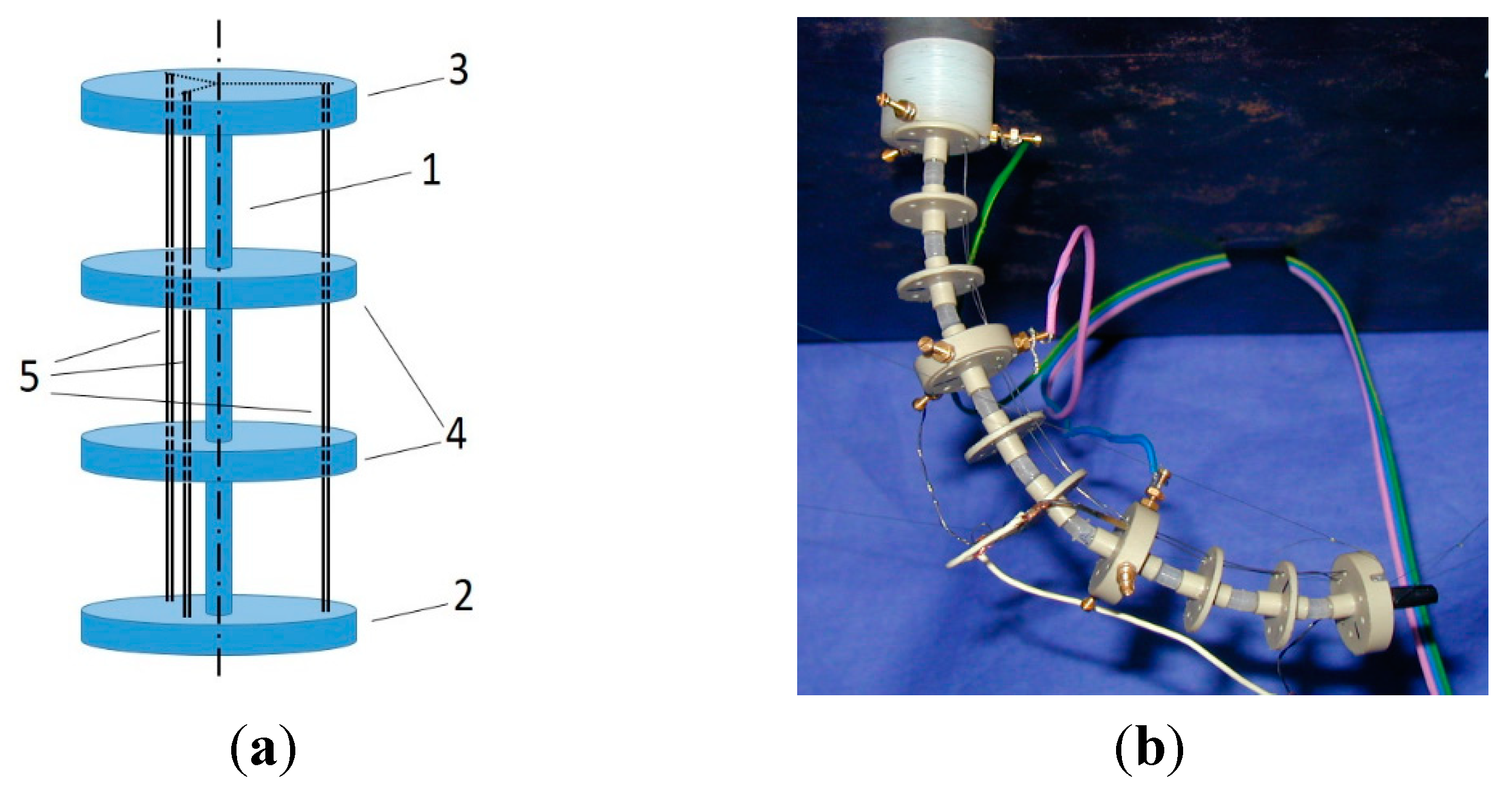
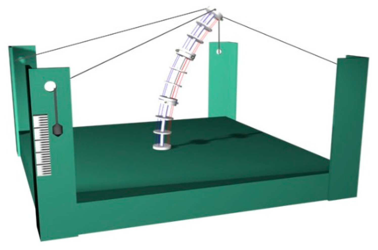
2. SMA-Actuated Module
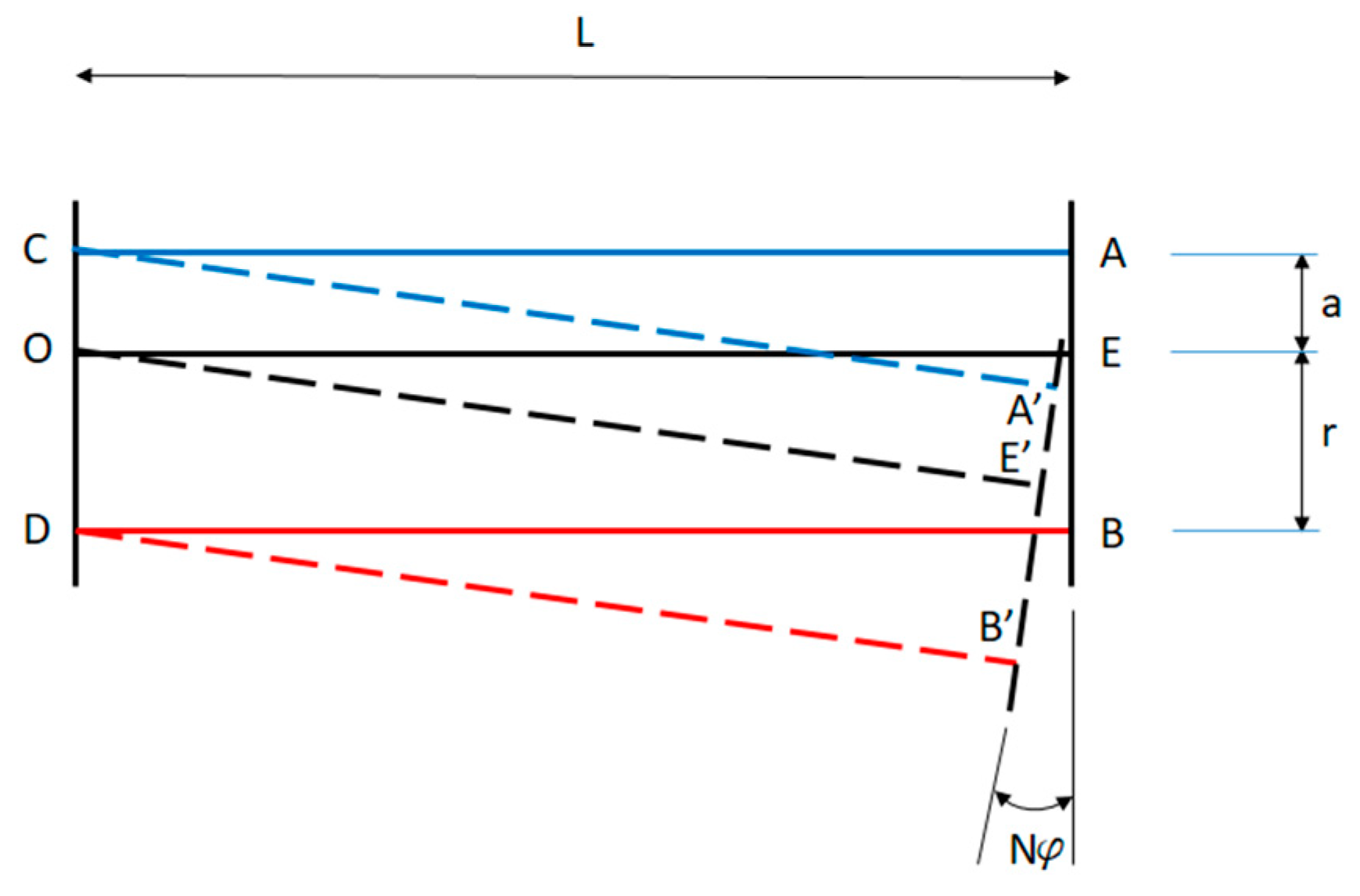
3. Mathematical Model
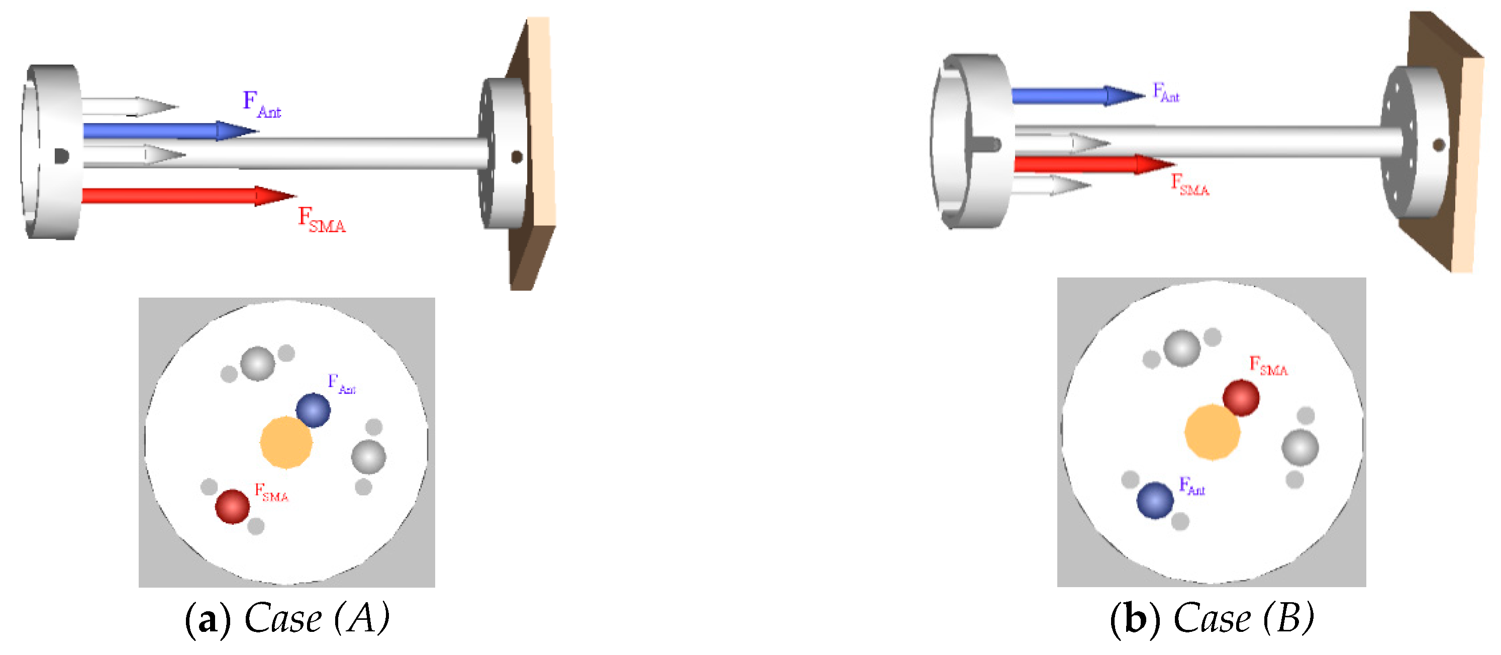
Case A
Case B
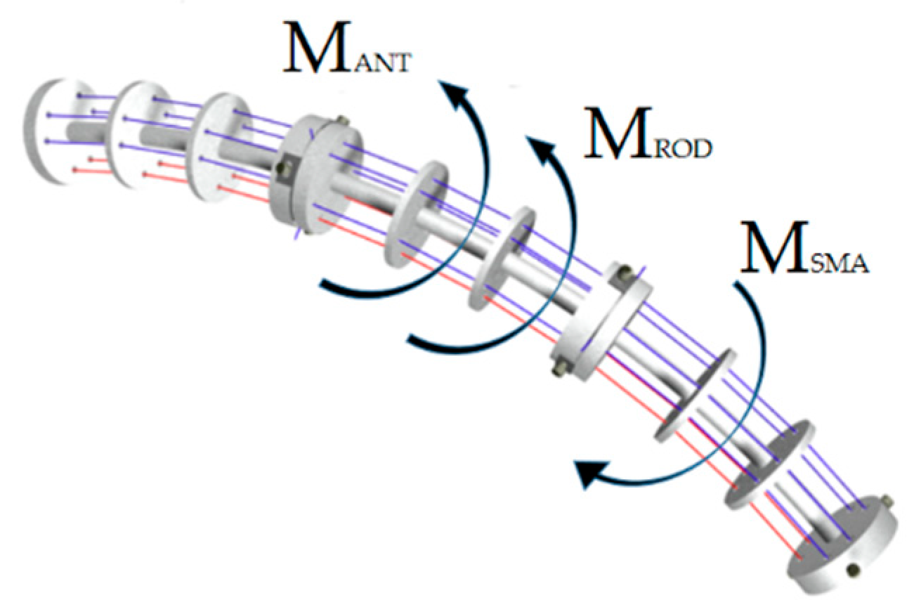
Moment of the SMA Force (One Wire)
Moment of the Antagonistic Force (One Wire)
Moment of the Elastic Reaction of the Central Rod
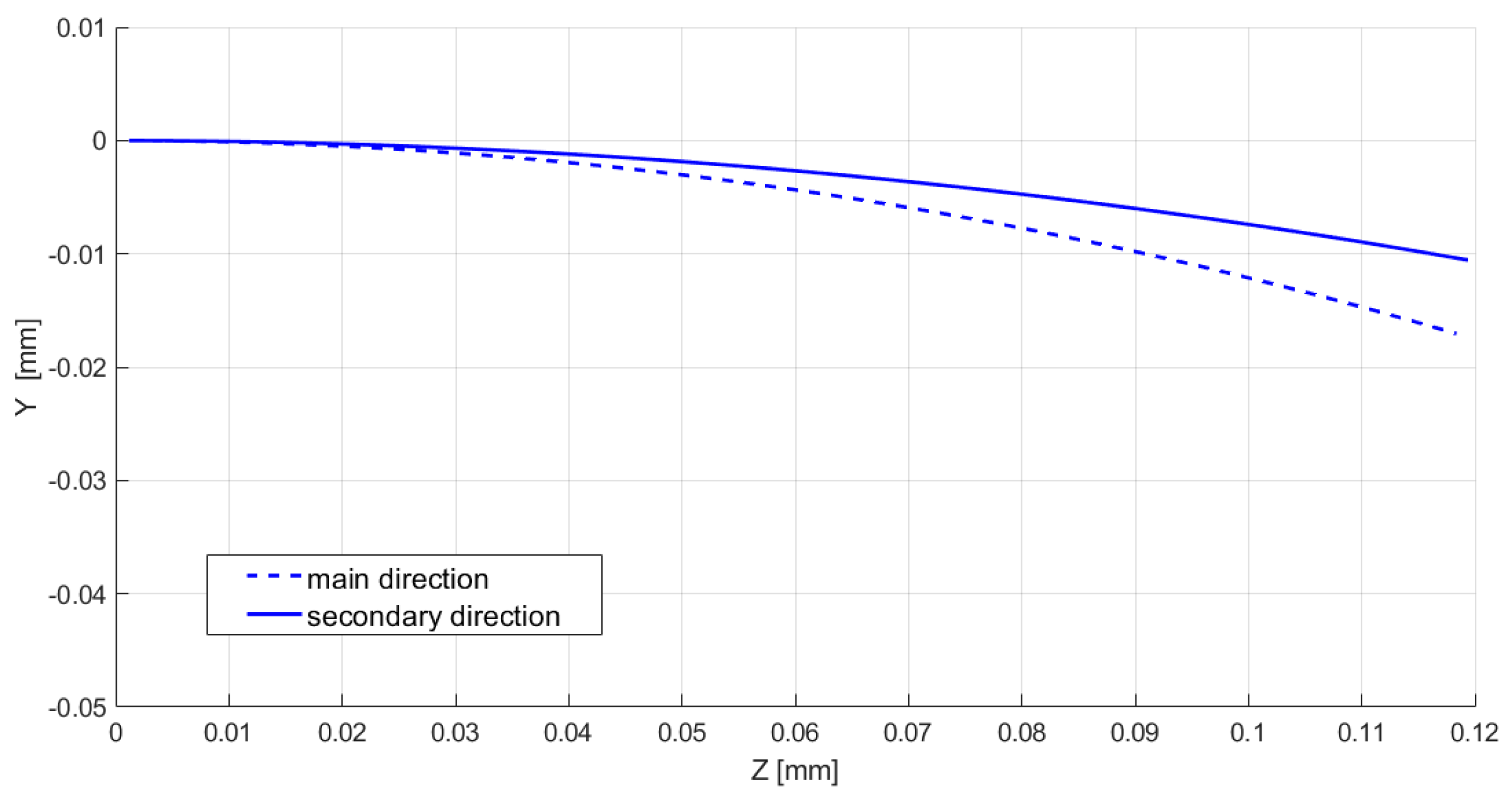
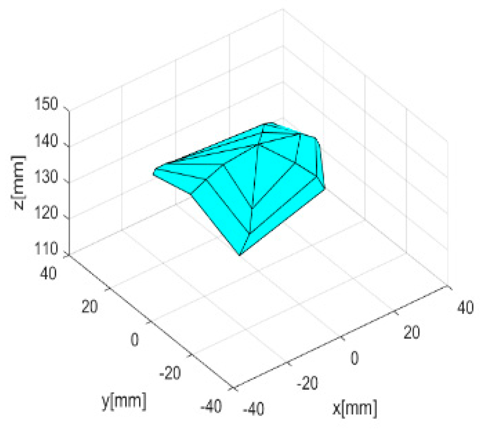
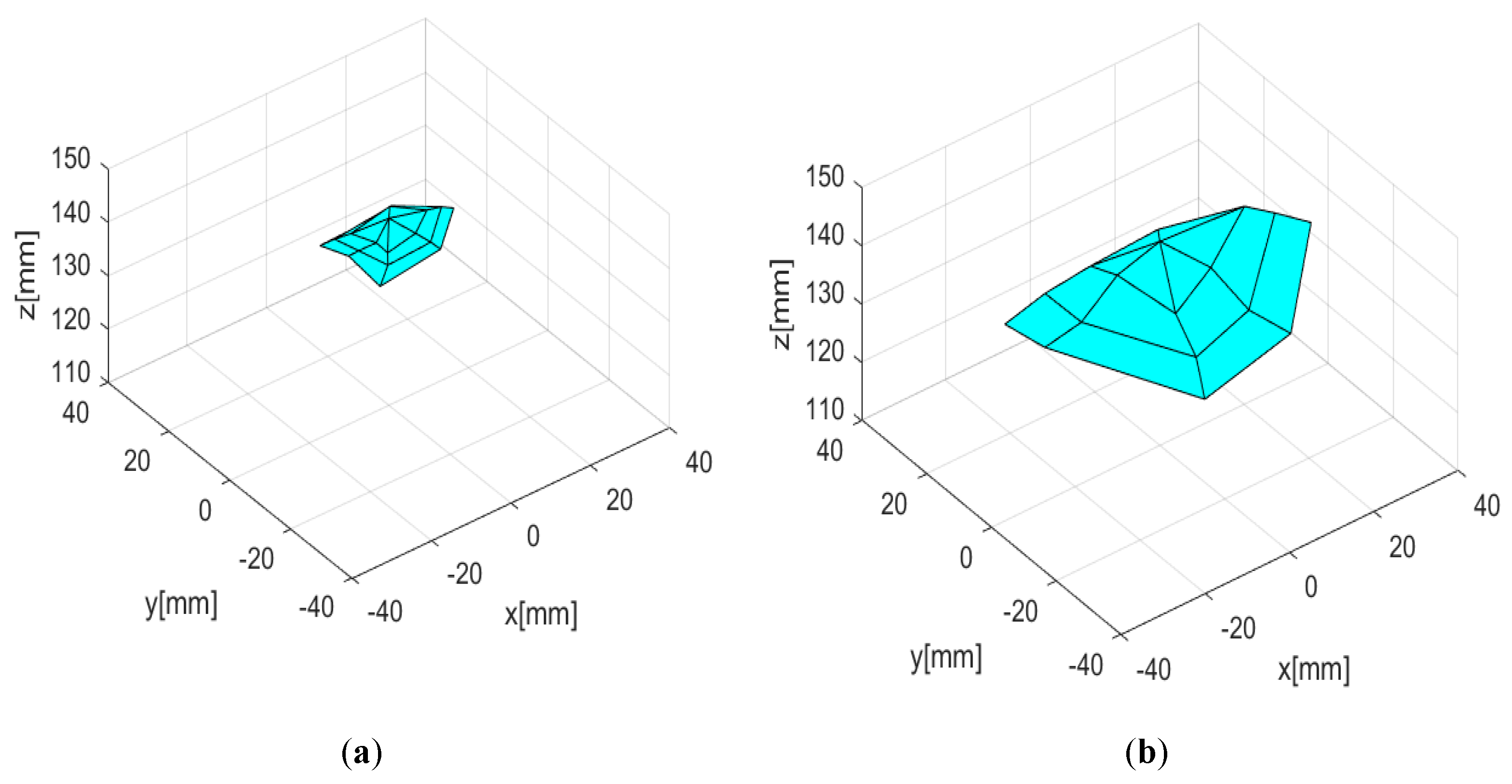
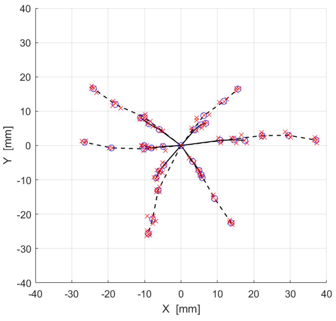
Model Results
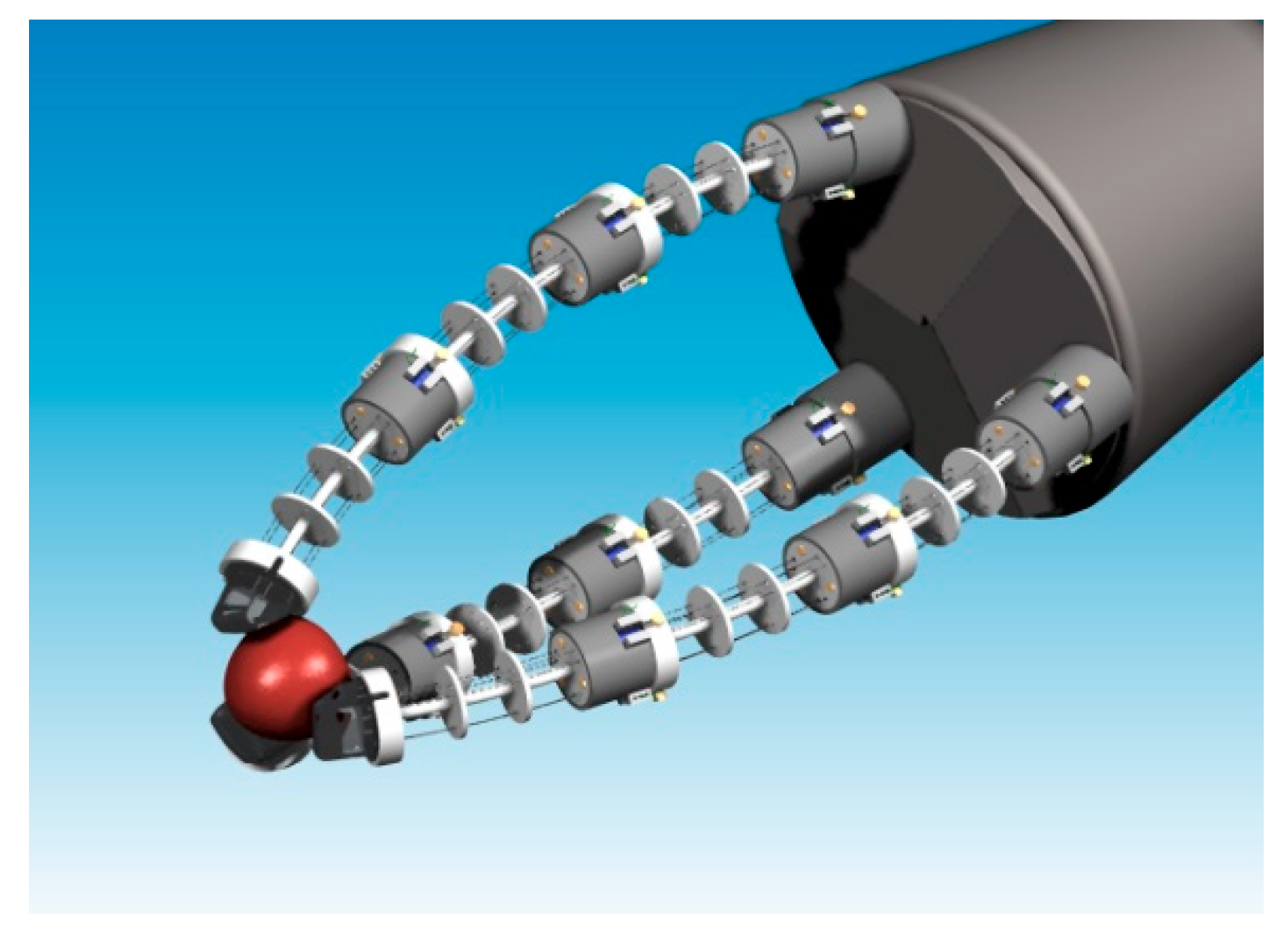
4. Prototypes Designs
5. Experimental Tests Bench, Procedure, and Results
6. New Prototype D
7. Discussion
Author Contributions
Funding
Conflicts of Interest
References
- Hodgson, D.E.; Wu, M.H.; Biermann, R.J. Properties and Selection: Nonferrous Alloys and Special-Purpose Materials. In ASM Handbook; ASM International: Metals Park, OH, USA, 1990; Volume 2, pp. 897–902. [Google Scholar]
- Raparelli, T.; Beomonte Zobel, P.; Durante, F. Mechanical design of a 3-dof parallel robot actuated by smart wires. In Proceedings of the 2nd European Conference on Mechanism Science, Cassino, Italy, 17–20 September 2008; pp. 271–278. [Google Scholar] [CrossRef]
- Raparelli, T.; Zobel, P.B.; Durante, F. A proposed methodology for the development of microgrippers: An application to a silicon device actuated by shape memory alloy wires. Int. J. Mech. Eng. Technol. 2018, 9, 235–249. [Google Scholar]
- Lee, K-T.; Lee, G-Y.; Choi, J-O.; Wu, R.; Ahn, S-H. Design and Fabrication of a Smart Flexible Structure using Shape Memory Alloy Wire (SMA). In Proceedings of the 2010 3rd IEEE RAS & EMBS International Conference on Biomedical Robotics and Biomechatronics, Tokyo, Japan, 26–29 September 2010; pp. 599–603. [Google Scholar]
- Wang, Z.; Hang, G.; Li, J.; Wang, Y.; Xiao, K. A micro-robot fish with embedded SMA wire actuated flexible biomimetic fin. Sens. Actuators A 2008, 144, 354–360. [Google Scholar] [CrossRef]
- Fukuda, T.; Hosokai, H.; Kikuchi, I. Distributed type of actuators by shape memory alloy and its application to underwater mobile robotic mechanism. In Proceedings of the IEEE International conference on Robotics and Automation, Cincinnati, OH, USA, 13–18 May 1990; pp. 1316–1321. [Google Scholar] [CrossRef]
- Maffiodo, D.; Raparelli, T. Three-fingered gripper with flexure hinges actuated by shape memory alloy wires. Int. J. Autom. Technol. 2017, 11, 355–360. [Google Scholar] [CrossRef]
- Giataganas, P.; Evangeliou, N.; Koveos, Y.; Kelasidi, E.; Tzes, A. Design and experimental evaluation of an innovative SMA-based tendon-driven redundant endoscopic robotic surgical tool. In Proceedings of the 19th Mediterranean Conference on Control & Automation, Corfu, Greece, 20–3 June 2011; pp. 1071–1075. [Google Scholar]
- Duerig, T.; Pelton, A.; Stöckel, D. An overview of nitinol medical applications. Mater. Sci. Eng. A 1999, 273–275, 149–160. [Google Scholar] [CrossRef]
- Petrini, L.; Migliavacca, F. Biomedical Applications of Shape Memory Alloys. J. Metall. 2011, 2011, 501483. [Google Scholar] [CrossRef]
- Song, G.; Kelly, B.; Agrawal, B.N. Active position control of a shape memory alloy wire actuated composite beam. Smart Mater. Struct. 2000, 9, 711–716. [Google Scholar] [CrossRef]
- Lima, W.M.; Araujo, C.J.D.; Valenzuela, W.A.V.; Rocha Neto, J.S.D. Control of strain in a flexible beam using Ni-Ti-Cu shape memory alloy wire actuators. J. Braz. Soc. Mech. Sci. Eng. 2012, 34, 413–422. [Google Scholar] [CrossRef] [Green Version]
- Ikuta, K. Micro/miniature shape memory alloy actuator. In Proceedings of the IEEE International Conference on Robotics and Automation, Cincinnati, OH, USA, 13–18 May 1990; pp. 2156–2161. [Google Scholar] [CrossRef]
- Jani, J.M.; Leary, M.; Subic, A.; Gibson, M.A. A review of shape memory alloy research, applications and opportunities. Mater. Des. 2014, 56, 1078–1113. [Google Scholar] [CrossRef]
- Shameli, E.; Alasty, A.; Salaarieh, H. Stability analysis and nonlinear control of a miniature shape memory alloy actuatorfor precise applications. Mechatronics 2005, 15, 471–486. [Google Scholar] [CrossRef]
- Choi, S.B.; Han, Y.M.; Kim, J.H.; Cheong, C.C. Force tracking control of a flexible gripper featuring shape memory alloy actuators. Mechatronics 2001, 11, 677–690. [Google Scholar] [CrossRef]
- Maffiodo, D.; Raparelli, T. Resistance feedback of a shape memory alloy wire. Adv. Intell. Syst. Comput. 2016, 371, 97–104. [Google Scholar] [CrossRef]
- Tsugami, Y.; Barbiè, T.; Tadakuma, K.; Nishida, T. Development of Universal Parallel Gripper using Reformed Magnetorheological Fluid. In Proceedings of the 11th Asian Control Conference (ASCC) Gold Coast Convention Centre, Gold Coast, Australia, 17–20 December 2017. [Google Scholar]
- Felser, A.; Zieve, P.B.; Ernsdorff, B. Use of Synchronized Parallel Grippers in Fastener Injection Systems. SAE Technical Paper 2015. [Google Scholar] [CrossRef]
- Sudsang, A.; Ponce, J. New techniques for computing four-finger force closure grasps of polyhedral objects. In Proceedings of the IEEE International Conference on Robotics and Automation, Nagoya, Japan, 21–27 May 1995. [Google Scholar]
- Li, Z.; Hsu, P.; Sastry, S. Grasping and coordinated manipulation by a multifinger robot hand. Intl. J. Robot. Res. 1989, 8, 33–50. [Google Scholar]
- Datta, R.; Pradhan, S.; Bhattacharya, B. Analysis and Design Optimization of a Robotic Gripper Using Multiobjective Genetic Algorithm. IEEE Trans. Syst. Man Cybern. Syst. 2016, 46, 16–26. [Google Scholar] [CrossRef]
- Baliga, U.B.; Winston, S.J.; Sandeep, S. Design Optimization of Power Manipulator Gripper for Maximum Grip Force. Int. J. Eng. Res. Technol. 2014, 3, 134–140. [Google Scholar]
- Jia, Y.; Zhang, X.; Xu, Q. Design and optimization of a dual-axis PZT actuation gripper. In Proceedings of the IEEE International Conference on Robotics and Biomimetics (ROBIO 2014), Bali, Indonesia, 5–10 December 2014; pp. 321–325. [Google Scholar] [CrossRef]
- Modabberifar, M.; Spenko, M. A shape memory alloy-actuated gecko-inspired robotic gripper. Sens. Actuators A Phys. 2018, 276, 76–82. [Google Scholar] [CrossRef]
- Schulte, H.F., Jr. The characteristics of the McKibben artificial muscle. In The Application of External Power in Prosthetics and Orthotics; National Academy of Sciences-National Research Council: Washington, DC, USA, 1961; pp. 94–115. [Google Scholar]
- Inoue, K. Rubbertuators and applications for robots. In Robotics Research: The 4th International Symposium; Bolles, R., Roth, B., Eds.; MIT Press: Cambridge, MA, USA, 1988; pp. 57–63. [Google Scholar]
- Ferraresi, C.; Franco, W.; Quaglia, G. A novel bi-directional deformable fluid actuator. Proc. Inst. Mech. Eng. Part C 2014, 228, 2799–2809. [Google Scholar] [CrossRef]
- Yang, K.; Gu, C.L. A compact and flexible actuator based on shape memory alloy springs. J. Mech. Eng. Sci. 2008, 222, 1329–1337. [Google Scholar] [CrossRef]
- Torres-Jara, E.; Gilpin, K.; Karges, J.; Wood, R.J.; Russ, D. Compliant Modular Shape Memory Alloy Actuators. IEEE Rob. Autom. Mag. 2010, 17, 78–87. [Google Scholar] [CrossRef]
- Maffiodo, D.; Raparelli, T. Design and realization of a flexible finger actuated by shape memory alloy (SMA) wires. Int. J. Appl. Eng. Res. 2017, 12, 15635–15643. [Google Scholar]
- Maffiodo, D.; Raparelli, T. Experimental testing of a modular flexible actuator based on SMA wires. Int. J. Appl. Eng. Res. 2018, 13, 1465–1471. [Google Scholar]


| Central rod diameter (mm) | 2.6 |
| Total actuator length (mm) | 120 |
| Young’s modulus PTFE (MPa) | 450 |
| SMA wires’ positioning radius (mm) | 5 |
| SMA wire diameter (μm) | 250 |
| SMA wire shortening (%) | 5 |
| SMA Young modulus in martensitic phase (GPa) | 28 |
| SMA Young modulus in austenitic phase (GPa) | 75 |
| Main Direction | Secondary Direction | |
|---|---|---|
| Total SMA moment (Nm) | 0.0424 | 0.0454 |
| Total antagonistic moment (Nm) | 0.0400 | 0.0440 |
| Total central rod moment (Nm) | 0.0024 | 0.0014 |
| Total deformation angle Nf (rad) | 0.028 | 0.017 |
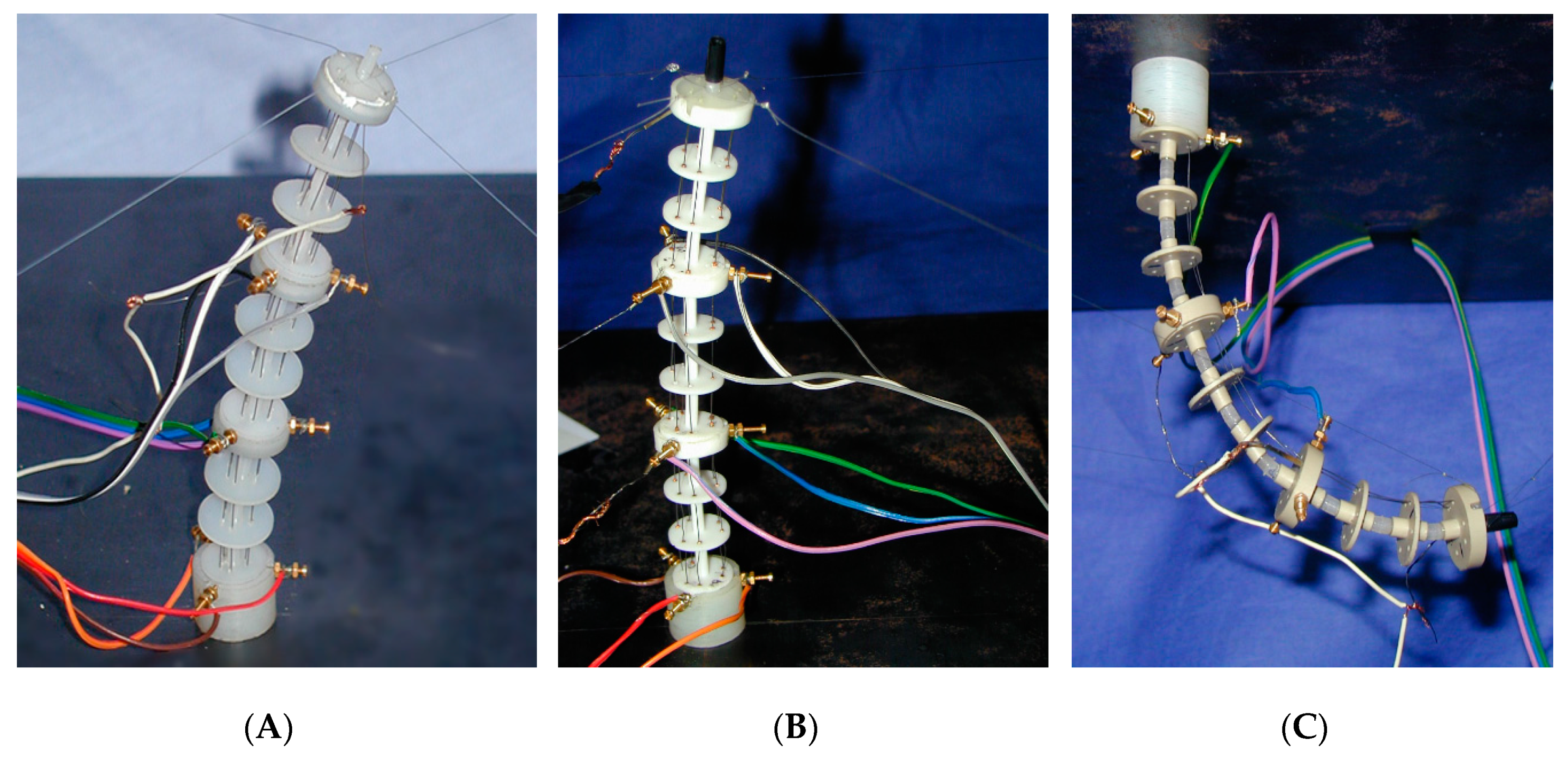
| Material | Young’s Modulus (MPa) | Melting Temperature (°C) | |
|---|---|---|---|
| (A) | Nylon | 800 | 120 |
| (B) | PTFE | 800 | 250 |
| (C) | PEEK1000/LIM | 4400/50 | 340 |
© 2019 by the authors. Licensee MDPI, Basel, Switzerland. This article is an open access article distributed under the terms and conditions of the Creative Commons Attribution (CC BY) license (http://creativecommons.org/licenses/by/4.0/).
Share and Cite
Maffiodo, D.; Raparelli, T. Flexible Fingers Based on Shape Memory Alloy Actuated Modules. Machines 2019, 7, 40. https://doi.org/10.3390/machines7020040
Maffiodo D, Raparelli T. Flexible Fingers Based on Shape Memory Alloy Actuated Modules. Machines. 2019; 7(2):40. https://doi.org/10.3390/machines7020040
Chicago/Turabian StyleMaffiodo, Daniela, and Terenziano Raparelli. 2019. "Flexible Fingers Based on Shape Memory Alloy Actuated Modules" Machines 7, no. 2: 40. https://doi.org/10.3390/machines7020040